CN109693449B - Recording device and liquid storage unit - Google Patents
Recording device and liquid storage unitDownload PDFInfo
- Publication number
- CN109693449B CN109693449BCN201811227806.9ACN201811227806ACN109693449BCN 109693449 BCN109693449 BCN 109693449BCN 201811227806 ACN201811227806 ACN 201811227806ACN 109693449 BCN109693449 BCN 109693449B
- Authority
- CN
- China
- Prior art keywords
- storage unit
- liquid storage
- recording
- medium
- liquid
- Prior art date
- Legal status (The legal status is an assumption and is not a legal conclusion. Google has not performed a legal analysis and makes no representation as to the accuracy of the status listed.)
- Active
Links
- 239000007788liquidSubstances0.000titleclaimsabstractdescription417
- 230000032258transportEffects0.000claimsdescription33
- 230000005540biological transmissionEffects0.000claimsdescription14
- 239000002184metalSubstances0.000claimsdescription9
- 238000012546transferMethods0.000claimsdescription6
- 238000011144upstream manufacturingMethods0.000abstractdescription15
- 239000000976inkSubstances0.000description37
- 238000012986modificationMethods0.000description32
- 230000004048modificationEffects0.000description32
- 238000001514detection methodMethods0.000description18
- 238000010586diagramMethods0.000description16
- 238000000926separation methodMethods0.000description8
- 238000000605extractionMethods0.000description5
- 238000012423maintenanceMethods0.000description4
- 230000007423decreaseEffects0.000description2
- 238000007599dischargingMethods0.000description2
- 230000002457bidirectional effectEffects0.000description1
- 230000015572biosynthetic processEffects0.000description1
- 239000003086colorantSubstances0.000description1
- 230000000593degrading effectEffects0.000description1
- 230000000694effectsEffects0.000description1
- 230000005484gravityEffects0.000description1
- 238000003780insertionMethods0.000description1
- 230000037431insertionEffects0.000description1
- 238000009434installationMethods0.000description1
- 230000002452interceptive effectEffects0.000description1
- 238000000034methodMethods0.000description1
Images


Classifications
- B—PERFORMING OPERATIONS; TRANSPORTING
- B41—PRINTING; LINING MACHINES; TYPEWRITERS; STAMPS
- B41J—TYPEWRITERS; SELECTIVE PRINTING MECHANISMS, i.e. MECHANISMS PRINTING OTHERWISE THAN FROM A FORME; CORRECTION OF TYPOGRAPHICAL ERRORS
- B41J2/00—Typewriters or selective printing mechanisms characterised by the printing or marking process for which they are designed
- B41J2/005—Typewriters or selective printing mechanisms characterised by the printing or marking process for which they are designed characterised by bringing liquid or particles selectively into contact with a printing material
- B41J2/01—Ink jet
- B41J2/17—Ink jet characterised by ink handling
- B41J2/175—Ink supply systems ; Circuit parts therefor
- B41J2/17503—Ink cartridges
- B41J2/1752—Mounting within the printer
- B41J2/17523—Ink connection
- B—PERFORMING OPERATIONS; TRANSPORTING
- B41—PRINTING; LINING MACHINES; TYPEWRITERS; STAMPS
- B41J—TYPEWRITERS; SELECTIVE PRINTING MECHANISMS, i.e. MECHANISMS PRINTING OTHERWISE THAN FROM A FORME; CORRECTION OF TYPOGRAPHICAL ERRORS
- B41J2/00—Typewriters or selective printing mechanisms characterised by the printing or marking process for which they are designed
- B41J2/005—Typewriters or selective printing mechanisms characterised by the printing or marking process for which they are designed characterised by bringing liquid or particles selectively into contact with a printing material
- B41J2/01—Ink jet
- B41J2/17—Ink jet characterised by ink handling
- B41J2/175—Ink supply systems ; Circuit parts therefor
- B41J2/17503—Ink cartridges
- B41J2/17506—Refilling of the cartridge
- B41J2/17509—Whilst mounted in the printer
- B—PERFORMING OPERATIONS; TRANSPORTING
- B41—PRINTING; LINING MACHINES; TYPEWRITERS; STAMPS
- B41J—TYPEWRITERS; SELECTIVE PRINTING MECHANISMS, i.e. MECHANISMS PRINTING OTHERWISE THAN FROM A FORME; CORRECTION OF TYPOGRAPHICAL ERRORS
- B41J13/00—Devices or arrangements of selective printing mechanisms, e.g. ink-jet printers or thermal printers, specially adapted for supporting or handling copy material in short lengths, e.g. sheets
- B41J13/10—Sheet holders, retainers, movable guides, or stationary guides
- B41J13/103—Sheet holders, retainers, movable guides, or stationary guides for the sheet feeding section
- B—PERFORMING OPERATIONS; TRANSPORTING
- B41—PRINTING; LINING MACHINES; TYPEWRITERS; STAMPS
- B41J—TYPEWRITERS; SELECTIVE PRINTING MECHANISMS, i.e. MECHANISMS PRINTING OTHERWISE THAN FROM A FORME; CORRECTION OF TYPOGRAPHICAL ERRORS
- B41J2/00—Typewriters or selective printing mechanisms characterised by the printing or marking process for which they are designed
- B41J2/005—Typewriters or selective printing mechanisms characterised by the printing or marking process for which they are designed characterised by bringing liquid or particles selectively into contact with a printing material
- B41J2/01—Ink jet
- B41J2/17—Ink jet characterised by ink handling
- B41J2/175—Ink supply systems ; Circuit parts therefor
- B41J2/17503—Ink cartridges
- B41J2/17513—Inner structure
- B—PERFORMING OPERATIONS; TRANSPORTING
- B41—PRINTING; LINING MACHINES; TYPEWRITERS; STAMPS
- B41J—TYPEWRITERS; SELECTIVE PRINTING MECHANISMS, i.e. MECHANISMS PRINTING OTHERWISE THAN FROM A FORME; CORRECTION OF TYPOGRAPHICAL ERRORS
- B41J2/00—Typewriters or selective printing mechanisms characterised by the printing or marking process for which they are designed
- B41J2/005—Typewriters or selective printing mechanisms characterised by the printing or marking process for which they are designed characterised by bringing liquid or particles selectively into contact with a printing material
- B41J2/01—Ink jet
- B41J2/17—Ink jet characterised by ink handling
- B41J2/175—Ink supply systems ; Circuit parts therefor
- B41J2/17503—Ink cartridges
- B41J2/1752—Mounting within the printer
- B—PERFORMING OPERATIONS; TRANSPORTING
- B41—PRINTING; LINING MACHINES; TYPEWRITERS; STAMPS
- B41J—TYPEWRITERS; SELECTIVE PRINTING MECHANISMS, i.e. MECHANISMS PRINTING OTHERWISE THAN FROM A FORME; CORRECTION OF TYPOGRAPHICAL ERRORS
- B41J2/00—Typewriters or selective printing mechanisms characterised by the printing or marking process for which they are designed
- B41J2/005—Typewriters or selective printing mechanisms characterised by the printing or marking process for which they are designed characterised by bringing liquid or particles selectively into contact with a printing material
- B41J2/01—Ink jet
- B41J2/17—Ink jet characterised by ink handling
- B41J2/175—Ink supply systems ; Circuit parts therefor
- B41J2/17503—Ink cartridges
- B41J2/17553—Outer structure
- B—PERFORMING OPERATIONS; TRANSPORTING
- B41—PRINTING; LINING MACHINES; TYPEWRITERS; STAMPS
- B41J—TYPEWRITERS; SELECTIVE PRINTING MECHANISMS, i.e. MECHANISMS PRINTING OTHERWISE THAN FROM A FORME; CORRECTION OF TYPOGRAPHICAL ERRORS
- B41J29/00—Details of, or accessories for, typewriters or selective printing mechanisms not otherwise provided for
- B41J29/02—Framework
- B—PERFORMING OPERATIONS; TRANSPORTING
- B41—PRINTING; LINING MACHINES; TYPEWRITERS; STAMPS
- B41J—TYPEWRITERS; SELECTIVE PRINTING MECHANISMS, i.e. MECHANISMS PRINTING OTHERWISE THAN FROM A FORME; CORRECTION OF TYPOGRAPHICAL ERRORS
- B41J29/00—Details of, or accessories for, typewriters or selective printing mechanisms not otherwise provided for
- B41J29/12—Guards, shields or dust excluders
- B41J29/13—Cases or covers
- B—PERFORMING OPERATIONS; TRANSPORTING
- B41—PRINTING; LINING MACHINES; TYPEWRITERS; STAMPS
- B41J—TYPEWRITERS; SELECTIVE PRINTING MECHANISMS, i.e. MECHANISMS PRINTING OTHERWISE THAN FROM A FORME; CORRECTION OF TYPOGRAPHICAL ERRORS
- B41J29/00—Details of, or accessories for, typewriters or selective printing mechanisms not otherwise provided for
- B41J29/38—Drives, motors, controls or automatic cut-off devices for the entire printing mechanism
Landscapes
- Ink Jet (AREA)
Abstract
Translated fromChinese
Description
Translated fromChinese在2017年10月24日提交的日本专利申请2017-205345和在2018年1月29日提交的日本专利申请2018-012745的全部公开内容以参考的方式通过引用并入本文中。The entire disclosures of Japanese Patent Application No. 2017-205345 filed on October 24, 2017 and Japanese Patent Application No. 2018-012745 filed on January 29, 2018 are incorporated herein by reference in their entirety.
技术领域technical field
本发明涉及一种将液体喷射到介质上进行记录的记录装置。此外,还涉及构成所述记录装置的液体收纳单元和介质收容单元。The present invention relates to a recording apparatus for recording by ejecting liquid onto a medium. In addition, it also relates to a liquid storage unit and a medium storage unit constituting the recording apparatus.
背景技术Background technique
以喷墨打印机为代表的记录装置中,有一些记录装置的结构具备:介质收容部,收容进行记录的介质,并且能够将介质提供给记录头;以及液体收容部,能够收容液体容器,该液体容器是装有供给至所述记录头的所述液体的液体包等。Among the recording apparatuses represented by inkjet printers, some of the recording apparatuses have a structure including: a medium accommodating portion for accommodating a medium to be recorded and capable of supplying the medium to a recording head; and a liquid accommodating portion for accommodating a liquid container, the liquid The container is a liquid pack or the like containing the liquid supplied to the recording head.
作为这样的记录装置,例如专利文献1中公开了一种记录装置,其具有:具备记录头的装置主体;和墨盒,在其内部收容有墨包,并且能够通过在设置于装置主体中的预定空间拔插来进行装卸。专利文献1所述的记录装置中,为了避免增加装置主体的设置面积,所述墨盒设置在供纸盒的下方,该供纸盒设在装置主体。As such a recording apparatus, for example,
专利文献:日本特开2015-139882号公报对于这种记录装置,要求其结构能够加设所述供纸盒,以便收容更多类型或数量的介质。但是,在专利文献1所记载的记录装置中,由于在装置主体供纸盒的下侧设有墨盒,因此进一步在供纸盒的下侧加设供纸盒的情况下,从下侧供纸盒输送介质的路径被配置在供纸盒的墨盒或供给油墨的供给路径等阻挡,因此不能够满足上述需求。Patent Document: Japanese Patent Application Laid-Open No. 2015-139882 For such a recording apparatus, it is required to have a structure capable of adding the paper feed cassette so as to accommodate more types or numbers of media. However, in the recording apparatus described in
另外,由于油墨具有泄漏时向下泄漏的性质,因此要求尽可能将墨盒配置在下侧。In addition, since the ink has a property of leaking downward when it leaks, it is required to arrange the ink cartridge on the lower side as much as possible.
发明内容SUMMARY OF THE INVENTION
鉴于这种情况,本发明的目的在于提供一种兼顾装置的可扩展性和适当配置油墨收容部这两者的结构。In view of such circumstances, an object of the present invention is to provide a structure in which both the expandability of the apparatus and the proper arrangement of the ink accommodating portion are achieved.
本发明的第一实施方式的记录装置用于解决上述问题,其特征在于,在层叠设置记录单元、液体收纳单元及至少一个介质收容单元的状态下,构成供给路径以及输送路径,所述记录单元具备通过将液体喷射到介质上而进行记录的记录部,所述液体收纳单元收纳液体容器,所述液体容器收容供给至所述记录部的所述液体,所述介质收容单元收容输送至所述记录部的所述介质,通过所述供给路径将所述液体从收纳在所述液体收纳单元的所述液体容器供给到记录部,通过所述输送路径将所述介质从所述介质收容单元输送至所述记录部的记录区域,所述液体收纳单元具备:供给连接部,连接所述液体容器和所述供给路径;以及液体收纳单元内输送路径,形成所述输送路径的一部分且具备输送所述介质的第一输送部。A recording apparatus according to a first embodiment of the present invention is intended to solve the above-mentioned problems, and is characterized in that a supply path and a transport path are configured in a state where a recording unit, a liquid storage unit, and at least one medium storage unit are provided in layers, and the recording unit The recording unit includes a recording unit that performs recording by ejecting a liquid onto a medium, the liquid storage unit accommodates a liquid container that accommodates the liquid supplied to the recording unit, and the medium storage unit accommodates the liquid supplied to the recording unit. The medium of the recording unit supplies the liquid from the liquid container accommodated in the liquid storage unit to the recording unit through the supply path, and conveys the medium from the medium storage unit through the conveyance path To a recording area of the recording unit, the liquid storage unit includes: a supply connection part that connects the liquid container and the supply path; and a liquid storage unit in-transport path that forms a part of the conveyance path and includes a conveyance location. The first conveying part of the medium.
根据本实施方式,所述液体收纳单元具备供给连接部和液体收纳单元内输送路径,因此可以改变相对于所述记录单元或所述介质收容单元的所述液体收纳单元的配置或增加所述介质收容单元的数量,所述供给连接部连接所述液体容器和所述供给路径,所述液体收纳单元内输送路径形成所述输送路径的一部分且具备输送所述介质的输送部。由此,能够提供一种记录装置,该记录装置的结构兼顾了装置的可扩展性和适当配置所述液体收纳单元这两者。According to the present embodiment, since the liquid storage unit includes the supply connection portion and the transport path in the liquid storage unit, the arrangement of the liquid storage unit relative to the recording unit or the medium storage unit can be changed or the medium can be added. The number of storage units, the supply connection portion connects the liquid container and the supply path, and the liquid storage unit transport path forms a part of the transport path and includes a transport portion that transports the medium. As a result, it is possible to provide a recording apparatus having a structure in which both the expandability of the apparatus and the appropriate arrangement of the liquid storage unit are achieved.
而且,所述记录单元构成为例如内置能够收容介质的托盘或能够手动供纸的情况下,也可以仅由所述记录单元和所述液体收纳单元构成记录装置。Further, when the recording unit is configured to have a built-in tray capable of accommodating a medium or to be capable of manual paper feeding, for example, the recording unit and the liquid storage unit may constitute only the recording device.
在第一实施方式的基础上,本发明的第二实施方式所述的记录装置的特征在于,所述液体收纳单元具备动力传递部,所述动力传递部设置在安装于该液体收纳单元下方的所述介质收容单元,并将输送所述介质的第二输送部的动力传递到第一输送部。In addition to the first embodiment, the recording apparatus according to the second embodiment of the present invention is characterized in that the liquid storage unit includes a power transmission portion, and the power transmission portion is provided in a power transmission portion mounted below the liquid storage unit. The medium storage unit transmits the power of the second conveying part that conveys the medium to the first conveying part.
根据本实施方式,能够利用设置在所述介质收容单元上的第二输送部的动力驱动所述第一输送部,所述介质收容单元安装在所述液体收纳单元下方。According to this embodiment, the first conveyance unit can be driven by the power of the second conveyance unit provided in the medium storage unit attached below the liquid storage unit.
在第一实施方式和第二实施方式的基础上,本发明的第三实施方式所述的记录装置的特征在于,所述液体收纳单元能够收纳多个所述液体容器,且具备收纳一个液体容器的第一收纳部以及设置在所述第一收纳部的上侧且收纳剩余液体容器的第二收纳部。In addition to the first and second embodiments, the recording apparatus according to the third embodiment of the present invention is characterized in that the liquid storage unit is capable of storing a plurality of the liquid containers, and includes a single liquid container. the first storage part and the second storage part which is provided on the upper side of the first storage part and accommodates the remaining liquid container.
根据本实施方式,所述液体收纳单元具备配置成两段的第一收纳部和第二收纳部,因此能够有效地收纳多个所述液体容器。According to the present embodiment, since the liquid storage unit includes the first storage portion and the second storage portion arranged in two stages, a plurality of the liquid containers can be efficiently stored.
在第三实施方式的基础上,本发明的第四实施方式所述的记录装置的特征在于,所述第一收纳部和所述第二收纳部构成为能够向装置前方抽出,用于多个所述液体容器的每个所述供给连接部配置在装置的后侧。In addition to the third embodiment, the recording apparatus according to the fourth embodiment of the present invention is characterized in that the first housing portion and the second housing portion are configured to be able to be drawn out to the front of the apparatus and used for a plurality of Each of the supply connections of the liquid container is arranged on the rear side of the device.
根据本实施方式,向装置前方抽出所述第一收纳部和所述第二收纳部,从而进行所述液体容器的更换。According to the present embodiment, the first storage portion and the second storage portion are pulled out to the front of the apparatus, and the liquid container is replaced.
在第四实施方式的基础上,本发明的第五实施方式所述的记录装置的特征在于,所述液体收纳单元内输送路径相对于所述供给连接部设置在所述装置的后侧。In addition to the fourth embodiment, the recording apparatus according to the fifth embodiment of the present invention is characterized in that the transport path in the liquid storage unit is provided on the rear side of the apparatus with respect to the supply connection portion.
根据本实施方式,能够将所述液体收纳单元内输送路径配置于不影响所述第一收纳部和所述第二收纳部的抽出的位置。According to the present embodiment, the transport path in the liquid storage unit can be arranged at a position that does not interfere with the extraction of the first storage portion and the second storage portion.
在第三实施方式的基础上,本发明的第六实施方式所述的记录装置的特征在于,所述第一收纳部和所述第二收纳部构成为能够向装置侧方的一侧抽出,用于多个所述液体容器的每个所述供给连接部配置于装置侧方的另一侧。In addition to the third embodiment, the recording apparatus according to the sixth embodiment of the present invention is characterized in that the first housing portion and the second housing portion are configured to be able to be drawn out to a side of the apparatus, Each of the supply connections for a plurality of the liquid containers is arranged on the other side of the device side.
根据本实施方式,通过在装置侧方的一侧将所述第一收纳部和所述第二收纳部抽出,从而进行所述液体容器的更换。According to this embodiment, the replacement of the liquid container is performed by pulling out the first storage portion and the second storage portion on one side of the apparatus.
在第六实施方式的基础上,本发明的第七实施方式所述的记录装置的特征在于,所述液体收纳单元内输送路径相对于所述第一收纳部和所述第二收纳部设置在装置的后侧。In addition to the sixth embodiment, the recording apparatus according to the seventh embodiment of the present invention is characterized in that the transport path in the liquid storage unit is provided at a position relative to the first storage portion and the second storage portion. rear side of the device.
根据本实施方式,能够将所述液体收纳单元内输送路径配置于不影响所述第一收纳部和所述第二收纳部的抽出的位置。According to the present embodiment, the transport path in the liquid storage unit can be arranged at a position that does not interfere with the extraction of the first storage portion and the second storage portion.
在第四实施方式到第七实施方式的任一项的基础上,本发明的第八实施方式所述的记录装置的特征在于,在与所述第一收纳部和所述第二收纳部的抽出方向相交的方向上,所述第一收纳部的宽度比所述第二收纳部的宽度更窄。In addition to any one of the fourth embodiment to the seventh embodiment, the recording apparatus according to the eighth embodiment of the present invention is characterized in that: The width of the first receiving portion is narrower than the width of the second receiving portion in a direction intersecting the drawing direction.
根据本实施方式,在与所述第一收纳部和所述第二收纳部的抽出方向相交的方向上,所述第一收纳部的宽度比所述第二收纳部的宽度更窄,因此能够将所述第二收纳部下方的空余空间用作例如配置其他组件的空间。According to the present embodiment, the width of the first accommodating portion is narrower than the width of the second accommodating portion in the direction intersecting the drawing direction of the first accommodating portion and the second accommodating portion, so that it is possible to The vacant space below the second storage portion is used, for example, as a space for arranging other components.
在第一实施方式到第八实施方式的任一项的基础上,本发明的第九实施方式所述的记录装置的特征在于,所述液体收纳单元的上部中至少一部分是由金属片形成的。In addition to any one of the first embodiment to the eighth embodiment, the recording apparatus according to the ninth embodiment of the present invention is characterized in that at least a part of the upper part of the liquid storage unit is formed of a metal sheet .
根据本实施方式,所述液体收纳单元的上部由金属片形成,因此可由金属片承受安装在上侧的所述记录单元或所述介质收容单元的重量。According to the present embodiment, since the upper portion of the liquid storage unit is formed of a metal sheet, the weight of the recording unit or the medium storage unit mounted on the upper side can be supported by the metal sheet.
在第九实施方式的基础上,本发明的第十实施方式所述的记录装置的特征在于,所述液体收纳单元具备:第一装卸部,设置在上侧且能够装卸于所述记录单元或所述介质收容单元;以及第二装卸部,设置在下侧且能够装卸于所述介质收容单元,所述第一装卸部是定位凸部,形成在所述金属片上部且插入到设置于所述记录单元或所述介质收容单元的底部的凹部,所述第二装卸部是定位凹部,在所述液体收纳单元的底部形成有开口,且接受设置在所述介质收容单元上部的凸部。In addition to the ninth aspect, the recording apparatus according to the tenth aspect of the present invention is characterized in that the liquid storage unit includes a first attaching and detaching portion provided on an upper side and detachable from the recording unit or the recording unit. the medium accommodating unit; and a second attaching and detaching portion provided on the lower side and detachable from the medium accommodating unit, the first attaching and detaching portion being a positioning convex portion formed on the upper portion of the metal sheet and inserted into the A concave portion at the bottom of the recording unit or the medium storage unit, the second attaching and detaching portion is a positioning concave portion, an opening is formed in the bottom of the liquid storage unit, and the convex portion provided on the upper portion of the medium storage unit is received.
根据本实施方式能够容易地形成连接了其他单元和所述液体收纳单元的结构。According to the present embodiment, a structure in which other units and the liquid storage unit are connected can be easily formed.
在第一实施方式到第十实施方式的任一项的基础上,本发明的第十一实施方式所述的记录装置的特征在于,所述记录单元具备内置介质收容部,所述内置介质收容部内置于所述记录单元而收容被送到所述记录部的介质。In addition to any one of the first to tenth embodiments, the recording apparatus according to the eleventh embodiment of the present invention is characterized in that the recording unit includes a built-in medium accommodating portion that accommodates the built-in medium. The part is built in the recording unit and accommodates the medium sent to the recording part.
根据本实施方式,作为所述记录单元具备所述内置介质收容部的结构的记录装置能够获得与第一实施方式至第十实施方式中的任一方式相同的作用效果。According to the present embodiment, the recording apparatus having the structure including the built-in medium accommodating portion as the recording unit can obtain the same functions and effects as those of any one of the first to tenth embodiments.
在第一实施方式到第十一实施方式的任一项的基础上,本发明的第十二实施方式所述的记录装置的特征在于,所述液体收纳单元具备:液体收纳单元主体;内部构件,以可装卸的方式安装于所述液体收纳单元主体,且形成所述液体收纳单元内输送路径的一部分;以及外部构件,构成为相对于所述内部构件能够在关闭状态和打开状态之间进行切换,在所述关闭状态下与所述内部构件一起形成所述液体收纳单元内输送路径,在所述打开状态下开放所述液体收纳单元内输送路径,所述第一输送部具有:驱动辊,设置于所述液体收纳单元主体;以及从动辊,被所述外部构件保持,在所述外部构件处于所述关闭状态下与所述驱动辊形成夹持状态,在所述外部构件从所述关闭状态切换到所述打开状态时,解除与所述驱动辊形成的夹持状态,在与所述外部构件一起从所述液体收纳单元主体拆除所述内部构件时,所述从动辊也与所述外部构件一起被拆除,所述驱动辊被所述液体收纳单元主体保持。In addition to any one of the first to eleventh embodiments, the recording apparatus according to the twelfth embodiment of the present invention is characterized in that the liquid storage unit includes: a liquid storage unit main body; an internal member , which is detachably attached to the main body of the liquid storage unit, and forms a part of the conveying path in the liquid storage unit; switching so as to form a transport path in the liquid storage unit together with the internal member in the closed state, and to open the transport path in the liquid storage unit in the open state, and the first transport portion includes a drive roller a driven roller, which is held by the external member, and forms a nip state with the driving roller when the external member is in the closed state, and is driven from the external member from the external member. When the closed state is switched to the open state, the nipping state formed with the driving roller is released, and the driven roller is also removed when the inner member is removed from the liquid storage unit main body together with the outer member. Removed together with the outer member, the drive roller is held by the liquid storage unit main body.
根据本实施方式,与所述外部构件一起从所述液体收纳单元主体拆除所述内部构件时,所述从动辊也与所述外部构件一起被拆除,所述驱动辊被所述液体收纳单元主体保持。结果,每次从所述液体收纳单元主体装卸所述内部构件时,不用同时装卸所述驱动辊,因此能够维持所述驱动辊相对于所述液体收纳单元主体的组装精度,防止输送介质的精度下降。According to the present embodiment, when the inner member is removed from the liquid storage unit main body together with the outer member, the driven roller is also removed together with the outer member, and the driving roller is removed by the liquid storage unit. Subject remains. As a result, each time the internal member is attached and detached from the liquid storage unit main body, the drive roller does not need to be attached and detached at the same time, so the assembly accuracy of the drive roller with respect to the liquid storage unit main body can be maintained, and the accuracy of conveying the medium can be prevented. decline.
本发明的第十三实施方式所述的液体收纳单元的特征在于,设置在记录单元下侧而能够构成记录装置,所述记录单元具备通过将液体喷射到介质上而进行记录的记录部,所述液体收纳单元具备:收纳部,收纳液体容器,所述液体容器收容供给至所述记录部的所述液体;第一装卸部,设置在上侧,且能够装卸于所述记录单元或所述介质收容单元,所述介质收容单元收容被送到所述记录部的所述介质;第二装卸部,设置在下侧,且能够装卸于所述介质收容单元;供给连接部,在所述第一装卸部安装有所述记录单元或所述介质收容单元的状态下,连接所述液体容器和供给路径,通过所述供给路径从所述液体容器向所述记录部供给所述液体;以及液体收纳单元内输送路径,在所述第二装卸部安装有所述介质收容单元的状态下,形成输送路径的一部分而输送所述介质,通过所述输送路径将所述介质从所述介质收容单元输送至所述记录部的记录区域。The liquid storage unit according to the thirteenth embodiment of the present invention is characterized in that it is provided on a lower side of a recording unit that includes a recording unit that performs recording by ejecting a liquid onto a medium, and can constitute a recording device, so that The liquid storage unit includes: a storage part that stores a liquid container that stores the liquid supplied to the recording part; a medium accommodating unit for accommodating the medium sent to the recording unit; a second attaching and detaching part provided on the lower side and detachable from the medium accommodating unit; a supply connecting part in the first connecting the liquid container and a supply path in a state in which the recording unit or the medium storage unit is mounted on the detachable part, and supplying the liquid from the liquid container to the recording part through the supply path; and a liquid storage An intra-unit conveyance path for conveying the medium by forming a part of the conveyance path in a state in which the medium storage unit is attached to the second attaching and detaching portion, and conveying the medium from the medium storage unit through the conveyance path to the recording area of the recording section.
根据本实施方式,能够形成所述液体收纳单元配置在所述记录单元的下侧的记录装置。由于所述液体收纳单元配置在所述记录单元的下侧,例如,即使从所述液体收纳单元意外泄漏液体,也可以降低泄漏的所述液体附着到所述记录单元的风险。According to the present embodiment, it is possible to form a recording apparatus in which the liquid storage unit is arranged below the recording unit. Since the liquid storage unit is arranged on the lower side of the recording unit, for example, even if liquid leaks accidentally from the liquid storage unit, the risk of the leaked liquid adhering to the recording unit can be reduced.
另外,由于所述液体收纳单元具备所述第二装卸部和所述液体收纳单元内输送路径,能够在所述液体收纳单元的下侧安装所述介质收容单元,即可改善所述记录装置的可扩展性。In addition, since the liquid storage unit includes the second attaching and detaching portion and the transport path in the liquid storage unit, the medium storage unit can be mounted on the lower side of the liquid storage unit, thereby improving the performance of the recording apparatus. Extensibility.
在第十三实施方式的基础上,本发明的第十四实施方式所述的液体收纳单元的特征在于,具备:液体收纳单元主体;内部构件,以可装卸的方式安装于所述液体收纳单元主体,且形成所述液体收纳单元内输送路径的一部分;以及外部构件,构成为相对于所述内部构件能够在关闭状态和打开状态之间进行切换,在所述关闭状态下与所述内部构件一起形成所述液体收纳单元内输送路径,在所述打开状态下开放所述液体收纳单元内输送路径,所述输送部具有:驱动辊,设置于所述液体收纳单元主体;以及从动辊,被所述外部构件保持,在所述外部构件处于所述关闭状态下与所述驱动辊形成夹持状态,在所述外部构件从所述关闭状态切换到所述打开状态时,解除与所述驱动辊形成的夹持状态,在与所述外部构件一起从所述液体收纳单元主体拆除所述内部构件时,所述从动辊也与所述外部构件一起被拆除,所述驱动辊被所述液体收纳单元主体保持。In addition to the thirteenth embodiment, the liquid storage unit according to the fourteenth embodiment of the present invention is characterized by comprising: a liquid storage unit main body; and an internal member detachably attached to the liquid storage unit. a main body that forms a part of a conveyance path in the liquid storage unit; and an external member configured to be switchable between a closed state and an open state with respect to the internal member, and an external member configured to be switchable with the internal member in the closed state The conveying path in the liquid storage unit is formed together, and the conveying path in the liquid storage unit is opened in the open state, and the conveying part includes: a driving roller provided on the main body of the liquid storage unit; and a driven roller, is held by the external member, forms a nip with the drive roller when the external member is in the closed state, and releases the contact with the drive roller when the external member is switched from the closed state to the open state In a nip state formed by a driving roller, when the inner member is removed from the liquid storage unit main body together with the outer member, the driven roller is also removed together with the outer member, and the driving roller is removed by the outer member. The liquid storage unit body is held.
根据本实施方式,与所述外部构件一起从所述液体收纳单元主体拆除所述内部构件时,所述从动辊也与所述外部构件一起被拆除,所述驱动辊被所述液体收纳单元主体保持。结果,每次从所述液体收纳单元主体装卸所述内部构件时,不用同时装卸所述驱动辊,因此能够维持所述驱动辊相对于所述液体收纳单元主体的组装精度,防止输送介质的精度下降。According to the present embodiment, when the inner member is removed from the liquid storage unit main body together with the outer member, the driven roller is also removed together with the outer member, and the driving roller is removed by the liquid storage unit. Subject remains. As a result, each time the internal member is attached and detached from the liquid storage unit main body, the drive roller does not need to be attached and detached at the same time, so the assembly accuracy of the drive roller with respect to the liquid storage unit main body can be maintained, and the accuracy of conveying the medium can be prevented. decline.
根据本发明的第十五实施方式的记录装置的特征在于,在层叠设置记录单元、液体收纳单元及至少一个介质收容单元的状态下,构成供给路径以及输送路径,所述记录单元具备通过将液体喷射到介质上而进行记录的记录部,所述液体收纳单元收纳液体容器,所述液体容器收容供给至所述记录部的所述液体,所述介质收容单元收容输送至所述记录部的所述介质,通过所述供给路径将所述液体从收纳在所述液体收纳单元的所述液体容器供给到记录部,通过所述输送路径将所述介质从所述介质收容单元输送至所述记录部的记录区域,所述介质收容单元具备:介质收容部,收容所述介质;供给部,将所述介质从所述介质收容部送到所述输送路径;以及通道部,供所述供给路径的一部分通过。A recording apparatus according to a fifteenth embodiment of the present invention is characterized in that a supply path and a conveyance path are configured in a state in which a recording unit, a liquid storage unit, and at least one medium storage unit are provided in layers, and the recording unit includes a liquid A recording unit that performs recording by ejecting a medium, the liquid storage unit accommodates a liquid container that accommodates the liquid supplied to the recording unit, and the medium storage unit accommodates the liquid to be fed to the recording unit. The medium is supplied from the liquid container accommodated in the liquid storage unit to the recording unit through the supply path, and the medium is conveyed from the medium storage unit to the recording unit through the conveyance path The medium storage unit includes: a medium storage part for storing the medium; a supply part for sending the medium from the medium storage part to the conveying path; and a channel part for supplying the supply path part of the pass.
根据本实施方式,即使增加所述介质收容单元的数量,也能形成所述供给路径,因此可以改善装置的可扩展性。此外,相比于所述记录单元和所述介质收容单元,所述液体收纳单元的位置在更下侧。由此,能够提供一种记录装置,该记录装置具有兼顾装置的可扩展性和适当配置所述液体收纳单元的结构。According to the present embodiment, the supply path can be formed even if the number of the medium housing units is increased, so the expandability of the apparatus can be improved. In addition, the position of the liquid storage unit is lower than that of the recording unit and the medium storage unit. As a result, it is possible to provide a recording apparatus having a structure in which both the expandability of the apparatus and the liquid storage unit are appropriately arranged.
在第十五实施方式的基础上,本发明的第十六实施方式所述的记录装置的特征在于,所述供给路径是由供所述液体流通的管形成的,所述通道部是供所述管通过的空间。In addition to the fifteenth embodiment, the recording apparatus according to the sixteenth embodiment of the present invention is characterized in that the supply path is formed of a tube through which the liquid flows, and the channel portion is a the space through which the tube passes.
根据本实施方式,能够很容易地实现将液体从所述液体收纳单元经由所述介质收容单元而送到所述记录单元的结构。According to the present embodiment, it is possible to easily realize a configuration in which liquid is sent from the liquid storage unit to the recording unit via the medium storage unit.
在第十五实施方式的基础上,本发明的第十七实施方式所述的记录装置的特征在于,所述通道部具备转接路径而构成,所述转接路径是对作为设置在所述记录单元侧的所述供给路径的第一供给路径与作为设置在所述液体收纳单元侧的所述供给路径的第二供给路径进行转接的所述供给路径。In addition to the fifteenth embodiment, the recording apparatus according to the seventeenth embodiment of the present invention is characterized in that the channel portion is configured to include a switching path, and the switching path is a pair of The first supply path of the supply path on the recording unit side and the second supply path which is the supply path provided on the liquid storage unit side are connected to the supply path.
根据本实施方式,能够很容易地实现将液体从所述液体收纳单元经由所述介质收容单元而送到所述记录单元的结构。According to the present embodiment, it is possible to easily realize a configuration in which liquid is sent from the liquid storage unit to the recording unit via the medium storage unit.
本发明的第十八实施方式所述的介质收容单元的特征在于,与液体收纳单元一起设置在记录单元的下侧而能够构成记录装置,所述记录单元具备通过将液体喷射到介质上进行记录的记录部;所述液体收纳单元收纳液体容器收纳有收容供给至所述记录部的所述液体的液体容器,其具备:上侧装卸部,设在上侧,可装卸到所述记录单元;下侧装卸部,设在下侧,可装卸到所述液体收纳单元;介质收容部,收纳所述介质;供给部,在所述上侧装卸部上安装有所述记录单元、在所述下侧装卸部上安装有所述液体收纳单元的状态下,将所述介质从所述介质收容部输送至所述输送路径,所述输送路径将所述介质输送至由所述记录部形成的记录区域;以及,和通道部,能够使从收纳在所述液体收纳单元中的所述液体容器向所述记录部供给所述液体的所述供给路径的一部分通过。The medium storage unit according to the eighteenth embodiment of the present invention is characterized in that, together with the liquid storage unit, it is provided on the lower side of the recording unit to constitute a recording device, the recording unit having the capability of recording by ejecting liquid onto the medium. the recording unit; the liquid storage unit containing the liquid container accommodates the liquid container for accommodating the liquid supplied to the recording unit, and includes: an upper side attaching and detaching part, which is provided on the upper side and can be attached and detached to the recording unit; A lower side attaching and detaching part is provided on the lower side and can be attached and detached to the liquid storage unit; a medium storage part, which accommodates the medium; The medium is transported from the medium storage section to the transport path that transports the medium to a recording area formed by the recording section in a state where the liquid storage unit is mounted on the attaching and detaching section and, and a channel portion capable of passing a part of the supply path through which the liquid is supplied from the liquid container accommodated in the liquid storage unit to the recording portion.
根据本实施方式,即使增加所述介质收容单元的数量,也可以形成所述供给路径,因此能够改善所述记录装置的可扩展性。此外,相比于所述记录单元和所述介质收容单元,所述液体收纳单元的位置在更下侧。由此通过以上所述,能够获得一种兼顾所述记录装置的可扩展性和适当配置所述液体收纳单元的结构。According to the present embodiment, the supply path can be formed even if the number of the medium housing units is increased, so that the expandability of the recording apparatus can be improved. In addition, the position of the liquid storage unit is lower than that of the recording unit and the medium storage unit. As a result of the above, it is possible to obtain a structure in which both the scalability of the recording apparatus and the appropriate arrangement of the liquid storage unit are achieved.
附图说明Description of drawings
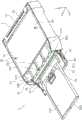
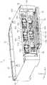
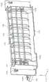
图1是第一实施方式所述的打印机的外观立体图。FIG. 1 is an external perspective view of the printer according to the first embodiment.
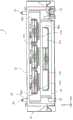
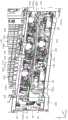
图2是第一实施方式所述的打印机的侧截面图。2 is a side sectional view of the printer according to the first embodiment.
图3是图2的主要部分的放大图。FIG. 3 is an enlarged view of the main part of FIG. 2 .
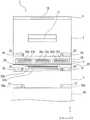
图4是第一实施方式所述的打印机的示意图。FIG. 4 is a schematic diagram of the printer according to the first embodiment.
图5是液体收纳单元的立体图。5 is a perspective view of a liquid storage unit.
图6是示出打开了液体收纳单元开闭盖的状态的立体图。6 is a perspective view showing a state in which the liquid storage unit opening and closing cover is opened.
图7是示出从液体收纳单元抽出了第一收纳部的抽屉式托盘的状态的立体图。FIG. 7 is a perspective view showing a state in which the drawer tray of the first storage unit is pulled out from the liquid storage unit.
图8是图6的主要部分放大图。FIG. 8 is an enlarged view of the main part of FIG. 6 .
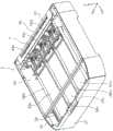
图9是示出从液体收纳单元拆除了上表面的状态的立体图。9 is a perspective view showing a state in which the upper surface is removed from the liquid storage unit.
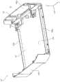
图10是示出液体收纳单元壳体的立体图。Fig. 10 is a perspective view showing a liquid storage unit case.
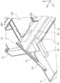
图11是从装置后侧看液体收纳单元的立体图。11 is a perspective view of the liquid storage unit viewed from the rear side of the apparatus.
图12是示出液体收纳单元后盖打开状态的立体图。12 is a perspective view showing a state in which the rear cover of the liquid storage unit is opened.
图13是示出从打开了后盖的液体收纳单元拆除了内盖的状态的立体图。13 is a perspective view showing a state in which the inner cover is removed from the liquid storage unit with the rear cover opened.
图14是液体收纳单元的Z-X平面的截面图。14 is a cross-sectional view of the liquid storage unit in the Z-X plane.
图15是供给连接部的示意图。FIG. 15 is a schematic diagram of a supply connection.
图16是第一实施方式所述的打印机的示意图。FIG. 16 is a schematic diagram of the printer according to the first embodiment.
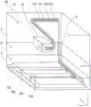
图17是表示第一输送路径及向设在第一输送路径上的第一驱动辊传递动力的动力传递部的立体图。17 is a perspective view showing a first conveyance path and a power transmission portion that transmits power to a first drive roller provided on the first conveyance path.
图18是示出第一实施方式所述的打印机的另一示例的立体图。FIG. 18 is a perspective view showing another example of the printer according to the first embodiment.
图19是示出第二实施方式所述的打印机的示意图。FIG. 19 is a schematic diagram showing the printer according to the second embodiment.
图20是示出第三实施方式所述的打印机的示意图。FIG. 20 is a schematic diagram showing the printer according to the third embodiment.
图21是示出第三实施方式所述的打印机的示意图。FIG. 21 is a schematic diagram showing the printer according to the third embodiment.
图22是通道部的示意性立体图。Fig. 22 is a schematic perspective view of a channel portion.
图23是示出第三实施方式所述的打印机的示意图。FIG. 23 is a schematic diagram showing the printer according to the third embodiment.
图24是说明供给路径的另一示例的示意图。FIG. 24 is a schematic diagram illustrating another example of the supply path.
图25是示出通道部的另一示例的示意性立体图。FIG. 25 is a schematic perspective view showing another example of the channel portion.
图26是第一实施方式的变形方式所述的打印机的后视立体图。26 is a rear perspective view of the printer according to a modification of the first embodiment.
图27是示出打开了第一实施方式的变形方式所述的液体收纳单元后盖的状态的后视图。27 is a rear view showing a state in which the rear cover of the liquid storage unit according to the modification of the first embodiment is opened.
图28是第一实施方式的变形方式所述的内盖和后盖的立体图。28 is a perspective view of an inner cover and a rear cover according to a modification of the first embodiment.
图29是第一实施方式的变形方式所述的内盖的立体图。29 is a perspective view of an inner cover according to a modification of the first embodiment.
图30是示出从第一实施方式的变形方式所述的液体收纳单元拆除内盖状态的立体图。30 is a perspective view showing a state in which the inner cover is removed from the liquid storage unit according to the modification of the first embodiment.
图31是示出图30中驱动辊的边缘部的放大图。FIG. 31 is an enlarged view showing the edge portion of the driving roller in FIG. 30 .
图32是示出在液体收纳单元安装有内盖状态下的驱动辊的边缘部的放大图。FIG. 32 is an enlarged view showing the edge portion of the drive roller in a state where the inner cover is attached to the liquid storage unit.
图33是示出后盖检测手段的立体图。FIG. 33 is a perspective view showing the back cover detection means.
图34是示出内盖装卸结构的另一实施方式的侧截面图。FIG. 34 is a side sectional view showing another embodiment of the inner cover attaching and detaching structure.
附图标记reference number
1、100…喷墨打印机(记录装置);2…记录单元;3、102、124…液体收纳单元;4…介质收容单元;5…扫描部;5a…盖体;6…内置托盘;7…进纸辊;8…第一辊;9…第二辊;10…记录头(记录部);11a、11b…从动辊;12a、12b…从动辊;13…输送辊对;14…出纸辊对;15…滑动托架;16…介质支撑部;17…出纸托盘;18…操作部;19…分离辊对;20…手动进纸盖;21…手动进纸托盘;22a、22b、22c、22d…管(供给路径);23…凹部;30…定位凸部(第一装卸部);31…上表面部;32…定位凹部(第二装卸部);33a、33b、33c、33d…液体容器;34…第一收纳部;35…第二收纳部;36…搁板;37…开闭盖;38a、38b、38c、38d…抽屉式托盘;39…保持部;40…壳体;41…引导槽;42…固定部;43a、43b、43c、43d…供给连接部;44a、44b、44c、44d…装卸部;45…针;46…限制部;47…接收部;48a、48b…侧壁;49a、49b、49c…肋部;50、106…后盖;51、104、122…内盖;52…开口部;53…第一从动辊;54…第一驱动辊;55、116…第一输送部;56…泵;57、108…窗口部;58…底面;60…动力传递部;61…第一齿轮;62…第二齿轮;63…第三齿轮;64…第四齿轮;70…纸张托盘;71…进纸辊;72…分离辊对;73…第二从动辊;74…第二驱动辊;75…第二输送部;76…凸部;77…凹部;80…喷墨打印机(记录装置);81…液体收纳单元;82…盖;90…喷墨打印机(记录装置);91…介质收容单元;92…壳体;93、93A…通道部;94…转接路径;95…第一供给路径;96…第二供给路径;97…凸部(上侧装卸部);98…凹部(下侧装卸部);102a…待紧固部;103…液体收纳单元主体;104a、106a…路径形成面;104b…紧固部;104c…凹部;106b…待检测部;110…驱动辊;112…旋转轴;114…从动辊;118…介质通过检测传感器;118a…检测杆;120…后盖开闭检测传感器;122a…闩锁部;124a…待闩锁部;A1、A2…箭头;P…纸张(介质);S1…共享输送路径(输送路径);S2…上游侧输送路径(输送路径);T…第一输送路径(输送路径);R…转向路径。1, 100...ink jet printer (recording device); 2...recording unit; 3, 102, 124...liquid storage unit; 4...medium storage unit; 5...scanner; 5a...cover; 6...built-in tray; 7... 8...first roller; 9...second roller; 10...recording head (recording section); 11a, 11b...driven rollers; 12a, 12b...driven rollers; 13...conveyor roller pair; 15...Slide carriage; 16...Media support; 17...Paper output tray; 18...Operation part; 19...Separation roller pair; 20...Manual feed cover; 21...Manual feed tray; 22a, 22b , 22c, 22d...pipe (supply path); 23...recessed portion; 30...positioning convex portion (first attachment and detachment portion); 31...upper surface portion; 32...positioning concave portion (second attachment and detachment portion); 33a, 33b, 33c, 33d...liquid container; 34...first storage portion; 35...second storage portion; 36...shelf; 37...opening/closing lid; 38a, 38b, 38c, 38d...drawer tray; 41...Guide groove; 42...Fixing part; 43a, 43b, 43c, 43d...Supply connection part; 44a, 44b, 44c, 44d...Removing part; , 48b...side walls; 49a, 49b, 49c...ribs; 50, 106...rear cover; 51, 104, 122...inner cover; 52...opening; 53...first driven roller; 54...first drive roller 55, 116...first conveying portion; 56...pump; 57, 108...window portion; 58...bottom surface; 60...power transmission portion; 61...first gear; 62...second gear; 63...third gear; 64 70...paper tray; 71...paper feed roller; 72...separation roller pair; 73...second driven roller; 74...second drive roller; 75...second conveying portion; 76...convex portion; 77 ...recessed portion; 80...inkjet printer (recording device); 81...liquid storage unit; 82...cap; 90...inkjet printer (recording device); 91...medium storage unit; 94...transfer path; 95...first supply path; 96...second supply path; 97...convex (upper attachment and detachment part); 98...recess (lower attachment and detachment); 102a...to-be-fastened part; 103 104a, 106a...path forming surface; 104b...fastening portion; 104c...recessed portion; 106b...to-be-detected portion; 110...driving roller; 112...rotating shaft; 114...driven roller; 118a...detection lever; 120...rear cover opening/closing detection sensor; 122a...latch portion; 124a...to-be-latched portion; A1, A2...arrow; P...paper (medium); path); S2...upstream side conveyance path (conveyance path); T...first conveyance path (conveyance path); R...return path.
具体实施方式Detailed ways
[第一实施方式][First Embodiment]
对本发明的一个实施方式所述的记录装置进行说明。作为记录装置的一示例,例举了喷墨打印机1(以下简称为打印机1)。A recording apparatus according to an embodiment of the present invention will be described. As an example of the recording apparatus, an ink jet printer 1 (hereinafter simply referred to as a printer 1 ) is exemplified.
图1是第一实施方式所述的打印机的外观立体图。图2是第一实施方式所述的打印机的侧截面图。图3是图2的主要部分放大图。图4是第一实施方式所述的打印机的示意图。图5是液体收纳单元的立体图。图6是示出打开了液体收纳单元开闭盖的状态的立体图。图7是示出从液体收纳单元抽出了第一收纳部的抽屉式托盘的状态的立体图。图8是图6的主要部分放大图。FIG. 1 is an external perspective view of the printer according to the first embodiment. 2 is a side sectional view of the printer according to the first embodiment. FIG. 3 is an enlarged view of a main part of FIG. 2 . FIG. 4 is a schematic diagram of the printer according to the first embodiment. 5 is a perspective view of a liquid storage unit. 6 is a perspective view showing a state in which the liquid storage unit opening and closing cover is opened. FIG. 7 is a perspective view showing a state in which the drawer tray of the first storage unit is pulled out from the liquid storage unit. FIG. 8 is an enlarged view of the main part of FIG. 6 .
图9是示出从液体收纳单元拆除了上表面的状态的立体图。图10是示出液体收纳单元壳体的立体图。图11是从装置后侧看液体收纳单元的立体图。图12是示出液体收纳单元后盖打开状态的立体图。图13是示出从打开了后盖的液体收纳单元拆除了内盖的状态的立体图。图14是液体收纳单元的Z-X平面的截面图。图15是供给连接部的示意图。图16是第一实施方式所述的打印机的示意图。图17是表示第一输送路径及向设在第一输送路径上的第一驱动辊传递动力的动力传递部的立体图。图18是示出第一实施方式所述的打印机的另一示例的立体图。9 is a perspective view showing a state in which the upper surface is removed from the liquid storage unit. Fig. 10 is a perspective view showing a liquid storage unit case. 11 is a perspective view of the liquid storage unit viewed from the rear side of the apparatus. 12 is a perspective view showing a state in which the rear cover of the liquid storage unit is opened. 13 is a perspective view showing a state in which the inner cover is removed from the liquid storage unit with the rear cover opened. 14 is a cross-sectional view of the liquid storage unit in the Z-X plane. Fig. 15 is a schematic diagram of a supply connection. FIG. 16 is a schematic diagram of the printer according to the first embodiment. 17 is a perspective view showing a first conveyance path and a power transmission portion that transmits power to a first drive roller provided on the first conveyance path. FIG. 18 is a perspective view showing another example of the printer according to the first embodiment.
图26是第一实施方式的变形方式所述的打印机的后视立体图,图27是示出打开了第一实施方式的变形方式所述的液体收纳单元后盖的状态的后视图,图28是第一实施方式的变形方式所述的内盖和后盖的立体图,图29是第一实施方式的变形方式所述的内盖的立体图。26 is a rear perspective view of the printer according to the modification of the first embodiment, FIG. 27 is a rear view showing a state in which the rear cover of the liquid storage unit according to the modification of the first embodiment is opened, and FIG. 28 is a FIG. 29 is a perspective view of the inner cover according to the modification of the first embodiment. FIG. 29 is a perspective view of the inner cover according to the modification of the first embodiment.
图30是示出从第一实施方式的变形方式所述的液体收纳单元拆除内盖状态的立体图,图31是示出图30中驱动辊的边缘部的放大图,图32是示出在液体收纳单元安装有内盖状态下的驱动辊的边缘部的放大图,图33是示出后盖检测手段的立体图,图34是示出内盖装卸结构的另一实施例的侧截面图。30 is a perspective view showing a state in which the inner cover is removed from the liquid storage unit according to the modification of the first embodiment, FIG. 31 is an enlarged view showing the edge portion of the driving roller in FIG. 30 , and FIG. FIG. 33 is a perspective view showing the rear cover detection means, and FIG. 34 is a side sectional view showing another example of the inner cover attaching and detaching structure.
其中,在各图所示的X-Y-Z坐标系中,X方向是记录头的扫描方向,即进行记录的介质的宽度方向。Y方向是装置的深度方向,即介质的长度向。Z方向是重力方向,即装置的高度方向。另外,将+Y方向侧作为装置的前侧,将-Y方向侧作为装置后侧。此外,从装置前侧观察时左侧为+X方向,右侧为-X方向。另外,+Z方向作为装置的上方(包括上部和上面等),-Z方向侧作为装置的下方(包括下部和下面等)。However, in the X-Y-Z coordinate system shown in each figure, the X direction is the scanning direction of the recording head, that is, the width direction of the medium on which recording is performed. The Y direction is the depth direction of the device, that is, the length direction of the medium. The Z direction is the direction of gravity, that is, the height direction of the device. In addition, let the +Y direction side be the front side of the apparatus, and let the -Y direction side be the apparatus rear side. In addition, when viewed from the front side of the apparatus, the left side is the +X direction, and the right side is the -X direction. In addition, the +Z direction refers to the upper part of the device (including the upper part and the upper surface, etc.), and the -Z direction side refers to the lower part of the device (including the lower part and the lower surface, etc.).
另外,在本说明书中,打印机1中输送纸张的输送方向称为“下游”,与其相反的方向称为“上游”。In addition, in this specification, the conveyance direction in which the paper is conveyed in the
下面,主要参照图1,对打印机1的概要和打印机1的纸张输送路径进行说明。Hereinafter, an outline of the
图1所示的打印机1是由记录单元2、液体收纳单元3和介质收容单元4层叠设置而成的。记录单元2、液体收纳单元3和介质收容单元4分别以可装卸的方式构成。The
记录单元2在内部具备各种组件,各种组件包括记录头10(图1中用虚线表示),其作为在作为“介质”的纸张上进行记录的“记录部”。记录头10是将作为“液体”的油墨喷射到纸张上进行记录的喷墨式记录头。The
在打印机1中,作为用于记录的纸张,可例举普通纸、厚纸、照相纸等。In the
打印机1不仅具备记录功能,还可以构成为例如具备文档读取功能、即扫描功能的多功能打印机。在本实施方式中,在记录单元2的上部设有扫描部5。扫描部5是平板式扫描仪,具备开闭文件台的盖体5a。盖体5a如下构成:如图1中双点划线所示的盖体5a那样,其以装置后侧(-Y方向)为轴旋转并打开。The
在装置上部前侧设有操作部18,其用于操作包括扫描部5的打印机1。An
液体收纳单元3收纳液体容器33a、33b、33c、33d(图7),该液体容器33a、33b、33c、33d收容供给至记录头10的油墨。The
此外,介质收容单元4收容输送至记录头10的纸张。介质收容单元4设有能够向装置前方抽出的纸张托盘70作为收容纸张的“介质收容部”。In addition, the
进而,在本实施方式中,记录单元2设有内置托盘6,内置托盘6内置在记录单元2中,并且作为“内部介质收容部”收容输送至记录头10的纸张。介质收容单元4的纸张托盘70或内置在记录单元2中的内置托盘6中收容有纸张,并将该纸张供给到记录头10进行记录。Furthermore, in the present embodiment, the
下面,对记录单元2的结构进行说明之后,接着说明液体收纳单元3和介质收容单元4的结构。Next, after the configuration of the
关于记录单元About the record unit
主要参考图2和图3对从记录单元2的内置托盘6(内置介质收容部)输送纸张进行说明,同时对记录单元2的结构进行说明。其中,图2中省略了对扫描部5的记载。The conveyance of paper from the built-in tray 6 (built-in medium accommodating portion) of the
记录单元2在底部具备收容多张纸张P的内置托盘6,能够从内置托盘6逐张供给纸张P。在图2和图3中,附图标记S1、S2所示的路径为打印机1的“输送路径”。“输送路径”中,在下述两种情况的任一情况下通过的路径为共享输送路径S1,这两种情况为从内置托盘6供纸的情况和从后述的由介质收容单元4的纸张托盘70供纸的情况。在图2和图3中,从位置A所示的位置排出到出纸托盘17为止的路径为共享输送路径S1。The
在层叠设置记录单元2、液体收纳单元3和介质收容单元4状态的打印机1中,“输送路径”是将纸张从介质收容单元4输送至由记录头10形成的记录区域的路径。In the
收容在内置托盘6中的纸张P通过进纸辊7(也称为拾纸辊)从内置托盘6被送到共享输送路径S1。附图标记19是分离辊对19,用于由进纸辊7送来多张纸张P时将纸张P分成一张。The paper P accommodated in the built-in
将已进入共享输送路径S1的纸张输送给第一辊8和第二辊9。其中,在图3中,附图标记11a、11b是通过第一辊8的旋转驱动而旋转的从动辊。附图标记12a、12b是通过第二辊9的旋转驱动而旋转的从动辊。在图2中,省略了从动辊11a、11b和从动辊12a、12b的附图标记。The sheet that has entered the shared conveyance path S1 is conveyed to the
第一辊8是用于翻转纸张的辊。由第一辊8弯曲翻转纸张后送到装置前侧(+Y方向),进而由第二辊9送到后述的输送辊对13。The
输送辊对13设置在第二辊9的介质输送方向下游侧且记录头10的介质输送方向上游侧。输送辊对13将纸张P输送到由记录头10形成的记录区域。The conveying
此外,在由记录头10形成的记录区域的介质输送方向下游侧设有出纸辊对14。Further, a pair of
输送辊对13和出纸辊对14如下构成:在位于输送辊对13和出纸辊对14之间的由记录头10形成的记录区域中,能够双向输送纸张P,其中双向为由记录头10进行记录的情况下的输送方向(+Y方向)及其反方向(-Y方向)。The pair of conveying
换而言之,输送辊对13和出纸辊对14如下构成:能够双向输送纸张,其中双向为朝向由记录头10形成的记录区域的介质输送方向和与所述介质输送方向相反的转向方向。In other words, the pair of conveying
输送辊对13和出纸辊对14分别将下辊作为驱动辊,由诸如电动机(未图示)等驱动源驱动其旋转。由所述驱动辊驱动上辊旋转。The conveying
例如,在所述驱动源为电动机的情况下,电动机能够双向旋转,即正向旋转和反向旋转,通过切换电动机的旋转方向,切换输送辊对13和出纸辊对14的旋转方向。结果,输送辊对13和出纸辊对14能够双向输送纸张P,两个方向为介质传送方向(+Y方向)和转向方向(-Y方向)。For example, when the driving source is an electric motor, the electric motor can rotate in both directions, that is, forward rotation and reverse rotation. As a result, the pair of conveying
由第二辊9输送的纸张P被输送辊对13夹持输送至记录头10的下方。The paper P conveyed by the
记录头10保持在滑动托架15,向输送至由记录头10形成的记录区域的纸张喷射油墨来进行记录,其中滑动托架15构成为能够在与介质输送方向(Y轴方向)相交的宽度方向(X轴方向)上移动。在记录头10的头表面(图1中的下表面)设有多个用于喷射油墨的喷嘴(未图示)。The
能够从设置在后述的液体收纳单元3上的液体容器33a、33b、33c、33d(参见图4;在图2和图3中示出了液体容器33a和液体容器)经由作为油墨“供给路径”的管22a、22b、22c、22d(图4)向记录头10的喷嘴供给油墨。From the
在层叠设置记录单元2、液体收纳单元3和介质收容单元4的状态下(图1和图4),管22a、22b、22c、22d从收纳在液体收纳单元3的液体容器33a、33b、33c、33d向记录头10供给油墨。In a state where the
作为一示例,液体容器33a收容黑色油墨,液体容器33b、33c、33d分别收容青色,品红色,黄色等各种颜色油墨。但是,在图2和图3中省略了管22a、22b、22c、22d的记载。As an example, the
在记录头10的下方,即在与记录头10相对的位置处设有支撑纸张P的介质支撑部16。Below the
由记录头10将油墨喷射到由介质支撑部16支撑并通过记录区域的纸张上来进行记录。The recording is performed by ejecting ink by the
其中,能够在介质支撑部16设置吸附机构用于将纸张吸附到介质支撑部16的支撑面上。所述吸附机构能够使用例如吸力吸附或静电吸附。由记录头10记录后的纸张P被出纸辊对14送出,排出到设置在装置前侧的出纸托盘17。Among them, a suction mechanism can be provided on the
此外,打印机1构成为能够进行双面记录,在记录完纸张P的第一面后,对所述第一面相反侧的第二面进行记录。进行双面记录时,记录完纸张P的第一面后,通过反向旋转输送辊对13和出纸辊对14将纸张P送到转向路径R(在图3中用虚线表示)后进行翻转。In addition, the
更具体地说,沿着转向路径R输送纸张P,该纸张P是由反向旋转的输送辊对13和出纸辊对14输送至所述转向方向(-Y方向)上的纸。转向路径R通过第二辊9与第一辊8的下方在第一辊8的下方与输送路径S1连接,再次由第一辊8翻转的同时沿着输送路径S1输送纸张P。More specifically, the paper P, which is the paper conveyed in the turning direction (-Y direction) by the reversely rotating conveying
由第一辊8翻转的纸张被第二辊9送出后,由正向旋转的输送辊对13向所述介质输送方向(+Y方向)输送,在所述第二面朝上的状态下再次送到记录头10的下方进行记录。由出纸辊对14输送记录完所述第二面的纸张P,将其排出到出纸托盘17。After the paper turned over by the
其中,打印机1中与记录相关的动作由控制部(未图示)控制。所述控制部控制与输送纸张相关的动作,即,输送辊对13和出纸辊对14等各种辊的驱动,除此之外控制由记录头10的记录或者滑动托架15的移动等。Of these, operations related to recording in the
此外,如图2所示地打开打印机1的手动进纸盖20,以便能够利用手动进纸托盘21(图2)供纸,在图1中手动进纸盖20设置在装置上部后侧。在此,省略了从手动进纸托盘21输送纸张的说明。Further, as shown in FIG. 2, the
关于液体收纳单元About the liquid storage unit
参考图3至图18对液体收纳单元3进行。The
如图5所示,液体收纳单元3在上侧具备可装卸于记录单元2的作为“第一装卸部”的定位凸部30(另见图16)。其中,如后述第三实施方式所示,定位凸部30可装卸于介质收容单元4。即定位凸部30相对于记录单元2或介质收容单元4以可装卸方式设置在液体收纳单元3的上侧。As shown in FIG. 5 , the
如图16所示,定位凸部30插入到设置在记录单元2的凹部23中,能够以预定位置关系、例如外表面齐平安装液体收纳单元3和设置在其上侧的单元(在本变更方式中是记录单元2),其中记录单元2配置在液体收纳单元3的上侧。As shown in FIG. 16, the positioning
将定位凸部30插入到设置在记录单元2底部的凹部23中来连接液体收纳单元3和记录单元2,从而能够容易地组装打印机1。The positioning
其中,能够设置锁定机构(未图示),用于锁定已连接的记录单元2与液体收纳单元3的连接。这也适用于后述的液体收纳单元3与介质收容单元4之间的连接。Here, a locking mechanism (not shown) can be provided for locking the connection between the
此外,在本实施方式中,由记录单元2、液体收纳单元3和介质收容单元4的各个外表面构成打印机1自身的外表面,例如,还可以在连接了各个单元之后用外壳覆盖以便不能看到单元之间的连接处,该外壳至少覆盖装置的侧面、前面和后面的一部分。In addition, in the present embodiment, the outer surfaces of the
对于液体收纳单元3而言,覆盖其上部的一部分的上表面部31由金属片形成,由金属片承受安装在上侧的单元的重量。In the
定位凸部30设置在金属片的上表面部31。The positioning protrusions 30 are provided on the
其中,如图16所示,在液体收纳单元3下侧设有作为”第二装卸部”的定位凹部32,定位凹部32可装卸于配置在液体收纳单元3下侧的介质收容单元4。对于定位凹部32将在后面进行说明。16 , a
关于第一收纳部和第二收纳部About the first storage unit and the second storage unit
接下来,如图4所示,液体收纳单元3能够收纳多个液体容器33a、33b、33c、33d,如图6所示,液体收纳单元3具备收纳一个液体容器33a的第一收纳部34,以及设置在第一收纳部34的上侧并收纳剩余液体容器33b、33c、33d的第二收纳部35。在本实施方式中,由搁板36分隔第一收纳部34与第二收纳部35。Next, as shown in FIG. 4, the
液体收纳单元3具备配置成两段的第一收纳部34和第二收纳部35,因此能够有效地收纳多个液体容器33a、33b、33c、33d。Since the
如图6所示,液体收纳单元3具备在前侧(+Y方向)开闭的开闭盖37,并构成为打开开闭盖37时能够向装置前方(+Y方向)抽出第一收纳部34和第二收纳部35。As shown in FIG. 6 , the
更具体而言,第一收纳部34具备能够向装置前方(+Y方向)抽出的抽屉式托盘38a,设计成通过抽出抽屉式托盘38a进行液体容器33a的装卸,该液体容器33a收纳在抽屉式托盘38a中。此外,第二收纳部35具备针对液体容器33b、33c、33d独立设置的抽屉式托盘38b、38c、38d。抽屉式托盘38b、38c、38d能够分别向装置前方(+Y方向)抽出。因此,能够容易地更换收纳在抽屉式托盘38b、38c、38d中的液体容器33b、33c、33d。More specifically, the first
其中,也可以将设置在第二收纳部35的抽屉式托盘38b、38c、38d构成为一个托盘,可以并排配置液体容器33b、33c、33d。Among them, the
在开闭盖37的内侧且与抽屉式托盘38a的抽出方向相交的方向(X轴方向)的两侧设有一对限制部46。A pair of restricting
限制部46是在如图7所示地抽出或插入抽屉式托盘38a时限制与抽屉式托盘38a的抽出方向相交的方向(X轴方向)上的位置的部件。The restricting
插入前或抽出后抽屉式托盘38a能够由开闭盖37的边缘37a(图7)支撑。由开闭盖37的边缘37a支撑抽屉式托盘38a,因此可以稳定且平稳地抽出或插入抽屉式托盘38a。The
此外,如图8所示,开闭盖37由安装在壳体40上的保持部39保持打开状态,其中壳体40的一端安装在开闭盖37,另一端构成液体收纳单元3的外观。Further, as shown in FIG. 8 , the opening and closing
保持部39具备引导槽41,设置在壳体40内侧的凸形固定部42与引导槽41卡合,在打开和关闭开闭盖37时,待固定的固定部42相对于引导槽41移动。The holding
如图6所示,保持部39设置在与抽屉式托盘38a、38b、38c、38d的抽出方向相交的方向(X轴方向)的两侧。As shown in FIG. 6, the holding|
关于供给连接部About the supply connection
此外,如图13所示,用于液体容器33a的供给连接部43a设置在第一收纳部34的装置后侧(-Y方向),用于多个液体容器33b、33c、33d的供给连接部43b、43c、43d设置在第二收纳部35的装置后侧(另见图9)。Further, as shown in FIG. 13, a
即,用于多个液体容器33a、33b、33c、33d的各个供给连接部43a、43b、43c、43d配置在装置后侧。That is, the respective
如图13所示,供给连接部43a、43b、43c、43d可分离地连接分别彼此对应的液体容器33a、33b、33c、33d(图4、图7)和管22a、22b、22c、22d(另见图4)。As shown in FIG. 13, the
在图13中,在管22a、22b、22c、22d靠近供给连接部43a、43b、43c、43d的一侧的端部设有用于连接和分离供给连接部43a、43b、43c、43d的装卸部44a、44b、44c、44d。在供给连接部43a、43b、43c、43d和装卸部44a、44b、44c、44d都设置止回阀(未图示),从而即使拆除装卸部44a、44b、44c、44d也不会泄露油墨。In Fig. 13, the end portions of the
其中,图13中仅示出了管22a、22b、22c、22d中靠近装卸部44a、44b、44c、44d的部分,省略了剩余部分。However, in FIG. 13, only the parts close to the attachment and
此外,如图13所示,在液体收纳单元3的后方,供给连接部43a的两侧设有泵56。通过泵56向管22a、22b、22c、22d内部施压,从而能够泵送油墨。Moreover, as shown in FIG. 13, the
如图15所示,在供给连接部43a、43b、43c、43d的+Y方向侧设置针45(另见图3)。图15中作为代表仅示出供给连接部43a,其他供给连接部43b、43c、43d也具有相同结构。As shown in FIG. 15, the
在图15中,针45插入到液体容器33a中。针45形成为中空,将液体容器33a内的油墨由针45通过供给连接部43a输送至管22a。In Fig. 15, the
当向装置前方(+Y方向侧)抽出抽屉式托盘38a(+Y方向侧)时,液体容器33a也向装置前方移动,因此从针45拔出液体容器33a。相反,安装液体容器33a时,通过将液体容器33a安装在抽屉式托盘38a上并将抽屉式托盘38a向深处推入,从而将针45插入液体容器33a。When the
此外,如图14所示,在与构成第一收纳部34的抽屉式托盘38a和构成第二收纳部35的抽屉式托盘38b、38c、38d的抽出方向相交的方向(X轴方向)上,构成为第一收纳部34的宽度比第二收纳部35的宽度更窄。由于第一收纳部34的宽度比第二收纳部35的宽度更窄,能够将图14中的第二收纳部35下方的空余空间用作例如配置其他组件的空间。本实施方式中,在所述空间设有定位凹部32。Further, as shown in FIG. 14 , in a direction (X-axis direction) intersecting with the drawing direction of the
定位凹部32是可装卸于配置在液体收纳单元3下侧的介质收容单元4的”第二装卸部”。The positioning
如图16所示,定位凹部32是在液体收纳单元3底部形成开口并接收设置在介质收容单元4上部的凸部76的组件。通过使液体收纳单元3的定位凹部32与介质收容单元4的凸部76卡合,能够将液体收纳单元3和设置在其下侧的介质收容单元4安装成其外部齐平。由此,能够容易地连接液体收纳单元3和介质收容单元4。As shown in FIG. 16 , the positioning
关于第一输送路径About the first conveying path
如图3所示,在层叠设置记录单元2、液体收纳单元3和介质收容单元4(参见图2)的状态下,打印机1具备构成“输送路径”的上游侧输送路径S2,“输送路径”用于从介质收容单元4向由记录头10形成的记录区域输送纸张。在图2和图3中,上游侧输送路径S2是比位置A更处于介质输送方向上游侧(-Z方向侧)的输送路径,由设置在液体收纳单元3下侧的介质收容单元4供给的纸张从上游侧输送路径S2进入共享输送路径S1,进行记录。As shown in FIG. 3 , in a state where the
而且,液体收纳单元3具备作为“收纳单元内输送路径”的第一输送路径T,第一输送路径T具备作为“输送部”的第一输送部55(图3),第一输送部55形成上游侧输送路径S2(输送路径)的一部分并输送纸张。Furthermore, the
由于液体收纳单元3具备第一输送路径T,当介质收容单元4设置在液体收纳单元3下侧时,能够使由介质收容单元4供给的纸张通过液体收纳单元3内,将其送到位于液体收纳单元3上侧的记录单元2。Since the
换而言之,通过液体收纳单元3具备第一输送路径T,如本实施方式那样能够实现在液体收纳单元3下侧设置介质收容单元4的打印机1结构。由此,通过层叠设置记录单元2、液体收纳单元3和介质收容单元4组装打印机时,能够将液体收纳单元3配置在更合适的位置上。In other words, the configuration of the
此外,可通过装卸记录单元2、介质收容单元4、和液体收纳单元3构成打印机1,能够分别制造每个单元后进行组合,因此组装打印机1变得容易。In addition, the
在本实施方式的液体收纳单元3中,第一输送路径T相比于供给连接部43a、43b、43c、43d设置在装置的后侧(-Y方向)(图3、图17)。In the
下面,对设置在液体收纳单元3的第一输送路径T的具体结构进行说明。Next, the specific structure of the 1st conveyance path T provided in the
如图11所示,液体收纳单元3的后侧(-Y方向)设有后盖50。如图12所示打开后盖50,就露出内盖51。此外、如图12所示在后盖50的内侧设置构成第一输送部55的第一从动辊53。第一驱动辊54与第一从动辊53成对构成第一输送部55,该第一驱动辊54如下构成:在内盖51的更内侧(+Y方向侧)安装旋转轴54a,第一驱动辊54从设置在内盖51的窗口部57(图17)暴露于第一从动辊53侧,且与第一从动辊53接触。As shown in FIG. 11 , a
如图12和图17所示,从上方观察液体收纳单元3时,内盖51的形状是向+Y方向凹陷,以使纸张能够通过背盖50和内盖51之间。此背盖50和内盖51之间的区域为第一输送路径T。As shown in FIGS. 12 and 17 , when the
通过在装置后侧设置第一输送路径T,能够形成第一输送路径T不影响抽出抽屉式托盘38a、38b、38c、38d的结构。By providing the first conveyance path T on the rear side of the apparatus, it is possible to form a structure in which the first conveyance path T does not affect the extraction of the
例如,用户能够容易地开闭后盖50,以便除去第一输送路径T中的卡纸或进行维修。For example, the user can easily open and close the
另一方面,如图13所示,拆除内盖51后露出供给连接部43a、43b、43c、43d或装卸部44a、44b、44c、44d或泵56等。内盖51通过固定螺钉等(未图示)固定在这些部件,使用户不容易触摸它们。On the other hand, as shown in FIG. 13, after removing the
此外,设置于第一输送路径T的第一输送部55的第一驱动辊54构成为通过动力传递部60从后述第二输送部75输送动力而进行驱动。第二输送部75设置在介质收容单元4。Moreover, the
在说明了介质收容单元4之后,对动力传递部60的结构进行说明。After the
关于介质收容单元About the media storage unit
图1和图2所示的介质收容单元4具备能够向装置前方(+Y方向)抽出的纸张托盘70。在图2和图3中,在纸张托盘70的装置后方(-Y方向)设有作为“供给部”的进纸辊71。进纸辊71将收容在纸张托盘70中的纸张P送到装置后方的上游侧输送路径S2。The
在进纸辊71的供给方向下游侧设置分离辊对72。分离辊对72在由进纸辊71送出多张纸张时将纸张分成一张。A
在图3中,在分离辊对72的下游侧设有第二输送部75。第二输送部75具备第二从动辊73和第二驱动辊74而构成。进纸辊71、分离辊对72的驱动辊以及第二驱动辊74由设置在介质收容单元4的驱动源(未图示)驱动。第二输送部75将纸张送到液体收纳单元3的第一输送路径T。从介质收容单元4供给的纸张通过包含第一输送路径T的上游侧输送路径S2,进而通过共享输送路径S1送到由记录头10形成的记录区域中。In FIG. 3 , the
如图16所示,在介质收容单元4的上部设有凸部76,其插入至液体收纳单元3的定位凹部32。此外,同样如图16所示,在介质收容单元4的下部设有凹部77。凹部77能够用于连接配置在介质收容单元4之下的单元(例如图16中虚线所示的第二个介质收容单元4A)。在第二个介质收容单元4A的上部设置的凸部76A插入到凹部77中,从而能够连接介质收容单元4和介质收容单元4A。由此,能够容易地形成层叠设置两个以上介质收容单元的打印机,增大装置的可扩展性。As shown in FIG. 16 , the upper portion of the
液体收纳单元的其他结构Other structures of the liquid storage unit
下面,对液体收纳单元3的其他结构进行说明。Next, another configuration of the
液体收纳单元3具备将第二输送部75的动力传递给第一传输单元55的动力传递部60,该第二输送部75设置在定位凹部32所安装的介质收容单元4且用于输送纸张。从而能够利用设置在介质收容单元4上的第二输送部75的动力来驱动第一输送部55,其中介质收容单元4安装于定位凹部32。The
下面,将参考图17说明动力传递部60的具体结构。Next, a specific structure of the
图17所示的动力传递部60具备设置在第一驱动辊54的旋转轴54a端部处的第一齿轮61、与第一齿轮61啮合的第二齿轮62、与第二齿轮62啮合的第三齿轮63以及与第三齿轮63啮合的第四齿轮64。The
第四齿轮64的一部分从设置在壳体40底部的开口部52(也参见图10)暴露于下方外侧。A part of the
并且,从开口部52露出的第四齿轮64的一部分与图3所示的设置在第二输送部75的第二驱动辊74的旋转轴的端部处的齿轮(都未图示)啮合。由此,将第二驱动辊74的旋转力传递到第四齿轮64,进而第二驱动辊74的旋转力由第三齿轮63和第二齿轮62传递到第一齿轮61。Also, a part of the
由此,能够利用第二驱动辊74(第二输送部75)的动力驱动设置在液体收纳单元3的第一驱动辊54(第一输送部55),第二驱动辊74设置在配置于液体收纳单元3下方的介质收容单元4。As a result, the first drive roller 54 (first conveyance unit 55 ) provided in the
如图10所示,在构成液体收纳单元3的壳体40的下部有接收部47,该接收部47是壳体40的底面58被X轴方向上的两侧侧壁48a、48,设置在Y轴方向上的两侧肋部49a、49b,以及设置在开口部52的边缘部上的肋部49c包围而成的。接收部47能够接收从液体容器33a、33b、33c、33d意外泄露的油墨。As shown in FIG. 10 , in the lower part of the
在本实施方式中,一体设置接收部47与壳体40,但是也可以设置与壳体40分体的托盘状接收部。能够将托盘状接收部向+Y方向侧抽出,例如与抽屉式托盘38a、38b、38c、38d相同。In this embodiment, the receiving
总结第一实施方式中说明的液体收纳单元3,液体收纳单元3具有以下结构。Summarizing the
即、液体收纳单元3设置在记录单元2的下侧以便构成记录装置,并且具备作为“收纳部”的第一收纳部34和第二收纳部35,所述第一收纳部34和第二收纳部35收纳用于收容供给记录头10的油墨的液体容器33a、33b、33c、33d。That is, the
此外,液体收纳单元3具备作为“第一装卸部”的定位凸部30和作为“第二装卸部”的定位凹部32,定位凸部30设置在液体收纳单元3的上侧且能够装卸于记录单元2或介质收容单元4,定位凹部32设置在液体收纳单元3的下侧且能够装卸于介质收容单元4。In addition, the
进而,液体收纳单元3具备供给连接部43a、43b、43c、43d和第一输送路径T,其中,供给连接部43a、43b、43c、43d在定位凸部30上安装有记录单元2或介质收容单元4的状态下以可分离地方式连接液体容器33a、33b、33c、33d和作为“供给路径”从液体容器33a、33b、33c、33向记录头10供给油墨的管22a、22b、22c、22d,第一输送路径T在定位凹部32上安装有介质收容单元4状态下具备输送纸张的第一输送部55,第一输送部55形成作为“输送路径”从介质收容单元4向由记录头10形成的记录区域输送纸张的上游侧输送路径S2的一部分。Further, the
由于液体收纳单元3的结构如上所述,层叠设置液体收纳单元3与记录单元2,或液体收纳单元3与记录单元2与介质收容单元4而能够容易地形成打印机1。Since the structure of the
此外,能够将液体收纳单元3配置在适当的位置。在本实施方式中,由于液体收纳单元3配置在记录单元2的下侧,例如即使油墨从液体收纳单元3意外地泄漏,也可以降低泄漏的油墨附着到记录单元2的风险。In addition, the
此外,由于液体收纳单元3具备定位凹部32和第一输送路径T,能够在液体收纳单元3的下侧安装介质收容单元4,即能够提高打印机1的可扩展性。In addition, since the
其中,如本实施方式的记录单元2,记录单元2具备内置托盘6时,如图18所示,最下面一段没有安装介质收容单元4,仅层叠设置记录单元2和液体收纳单元3,能够得到具有更紧凑结构的打印机1A。如此,可以增加打印机结构的自由度。Among them, when the
其中,本实施方式的结构为液体容器33a、33b、33c、33d和从液体容器33a、33b、33c、33d向记录头10供给油墨的管22a、22b、22c、22d通过供给连接部43a、43b、43c、43d能够彼此分离,并且能够更换每个液体容器33a、33b、33c、33d。In this embodiment, the
代替此结构,可以为例如在不分离液体容器33a、33b、33c、33d和管22a、22b、22c、22d的情况下连接供给连接部43a、43b、43c、43d的结构。根据此结构,能够在不从管22a、22b、22c、22d分离液体容器33a、33b、33c、33d并且将其收纳在第一收纳部34与第二收纳部35的状态下补充油墨。Instead of this structure, the
液体收纳单元的变形方式Deformation of the liquid storage unit
参考图26至图33对液体收纳单元的变形方式进行说明。本变形方式主要涉及内盖和后盖的结构,记录单元2的结构与第一实施方式相同。其中,图26、图27、图30和图33中未图示介质收容单元4。A modification of the liquid storage unit will be described with reference to FIGS. 26 to 33 . This modification mainly relates to the structures of the inner cover and the rear cover, and the structure of the
在图26中,打印机100具备记录单元2和液体收纳单元102。本变形方式中液体收纳单元102具备液体收纳单元主体103、作为“内部构件”的内盖104以及“外部构件”的后盖106。在液体收纳单元主体103的-Y方向侧(后表面侧)的端部上设有内盖104和后盖106。在本变形方式中,后盖106构成为相对于内盖104能够在关闭状态(未图示)和打开状态(图26至图28及图33)之间切换。具体而言,后盖106以-Z方向侧的端部为旋转支点相对于内盖104可旋转地安装在内盖104上。In FIG. 26 , the
在内盖104中,将-Y方向侧的一面(后面)作为路径形成面104a。另一方面,在后盖106中,图26和图28中将+Z方向侧的一面作为路径形成面106a。虽然未在图中示出,同样在本变形方式中,当后盖106相对于内盖104处于关闭状态时,路径形成面104a和路径形成面106a为在Y轴方向上隔着间隔而相对的状态。由此,关闭状态下的后盖106和内盖104之间,形成向Z轴方向延伸的作为液体收纳单元内输送路径的第一输送路径T(图2和图3)。In the
本变形方式中,如图27至图29所示,内盖104设有多个紧固部104b。作为一示例,有四处设有紧固部104b。如图30所示,在液体收纳单元主体103的-Y方向侧端部处形成有与紧固部104b对应的数量的待紧固部102a。作为一示例,有四处设有待紧固部102a。In this modification, as shown in FIGS. 27 to 29 , the
本变形方式中,通过将紧固部104b用紧固构件(未图示)紧固到待紧固部102a来将内盖104固定到液体收纳单元主体103。作为一示例,紧固构件(未图示)由螺钉或螺栓构成。In this modification, the
通过松开紧固构件(未图示)将其从内盖104拆除,能够从液体收纳单元主体103拆除内盖104。本变形方式中,如图28和图29所示,内盖104构成为能够与后盖106一起从液体收纳单元主体103拆除。本变形方式中,能够通过从内盖104拆除4个紧固构件来与后盖106一起从液体收纳单元主体103拆除内盖104,从而露出供给连接部43a、43b、43c、43d和泵56。结果,能够容易地进入供给连接部43a、43b、43c、43d和泵56,并且可以提高维护的可操作性。The
在内盖104的+Z方向侧端部,在X轴方向上间隔地形成多个窗口部108。如图32所示,在液体收纳单元主体103上安装有内盖104的状态下,在窗口部108配置了驱动辊110。在此状态下,驱动辊110的至少一部分比内盖104的路径形成面104a更向-Y方向侧凸出,即更向第一输送路径T内凸出。In the +Z direction side end portion of the
本变形方式中,如图30和图31所示,多个驱动辊110在X轴方向上间隔地安装在旋转轴112。如图30所示,旋转轴112可旋转地安装在液体收纳单元主体103。旋转轴112构成为通过接收来自第一动力传递部60的第一齿轮61的驱动力而旋转,该第一动力传递部60的第一齿轮61配置在旋转轴112的-X方向侧端部处。由此,驱动辊110也与旋转轴112一起旋转。In this modification, as shown in FIGS. 30 and 31 , the plurality of driving
在后盖106的X轴方向上间隔配置从动辊114,以使其一部分从路径形成面106a凸出。后盖106上配置有与驱动辊110对应的数量的从动辊114。The driven
当后盖106相对于内盖104处于关闭状态时,从动辊114抵接驱动辊110形成夹持状态。相反,当后盖106相对于内盖104从关闭状态旋转到打开状态时,解除驱动辊110与从动辊114的夹持状态,从而露出内盖104。其中,本变形方式中,驱动辊110和从动辊114构成第一输送路径T中作为“输送部”的第一输送部116(图26等)。When the
本变形方式中,将驱动辊110和旋转轴112安装在液体收纳单元主体103。结果,如图30和图31所示,与后盖106一起从液体收纳单元主体103拆除内盖104的情况下,驱动辊110和旋转轴112由液体收纳单元主体103保持并保持在液体收纳单元主体103侧。驱动辊110配置在形成于内盖104的窗口部108中,因此在液体收纳单元主体103装卸内盖104时,能够抑制内盖104和驱动辊110互相妨碍。其中,与后盖106一起从液体收纳单元主体103拆除内盖104时,从动辊114与后盖106一起被从液体收纳单元主体103拆除。In this modification, the driving
在此,在将驱动辊110和旋转轴112安装到内盖104的结构中,每次从液体收纳单元102装卸内盖104时,都需要从液体收纳单元主体103拆除或安装驱动辊110和旋转轴112。结果,有时无法使旋转轴112对于液体收纳单元主体103的组装精度稳定,例如无法使驱动辊110相对于第一输送路径T的平行度等稳定。Here, in the structure in which the
本变形方式中,使用将驱动辊110和旋转轴112保持在液体收纳单元主体103的结构,因此即使从液体收纳单元主体103装卸内盖104也能够维持旋转轴112相对于液体收纳单元主体103的组装精度。结果,能够防止第一输送路径T中输送介质的精度的降低。In this modification, since the structure in which the driving
在图30至图33中,在液体收纳单元主体103的-Y方向侧端部上,在对应内盖104的+Z方向侧端部的位置处配置介质通过检测传感器118。介质通过检测传感器118具备向第一输送路径T内部突出的检测杆118a。以可旋转的方式构成检测杆118a。在第一输送路径T中,从介质收容单元4(图1至图3)朝向记录单元2的记录头10(图2和图3)输送介质时,沿着第一输送路径T内部输送的介质的前端推动检测杆118a旋转。由此,介质通过检测传感器118能够检测第一输送路径T中的介质的输送。In FIGS. 30 to 33 , the medium
本变形方式中,介质通过检测传感器118设置在液体收纳单元主体103。由此,在液体收纳单元主体103上装卸内盖104时,没有必要从液体收纳单元主体103拆除介质通过检测传感器118,因此不会因装卸传感器而导致介质检测精度下降,能够稳定介质检测精度。In this modification, the medium
如图28和图33所示,在内盖104+X方向侧端部处形成有向+Y方向侧凹陷的凹部104c。在凹部104c中配置后盖开闭检测传感器120。另一方面,在后盖106的+X方向侧端部处形成有从路径形成面106a突出的待检测部106b(图33)。在本变形方式中,作为一示例,如下构成:后盖106对于内盖104处在关闭状态时,后盖开闭检测传感器120检测待检测部106b,检测出后盖106为关闭状态。As shown in FIGS. 28 and 33 , a
液体收纳单元102具备液体收纳单元主体103、内盖104以及后盖106,其中内盖104以可装卸的方式安装在液体收纳单元主体103上且形成第一输送路径T一部分,后盖106相对于内盖104能够在关闭状态和打开状态之间切换,在关闭状态下与内盖104一起形成第一输送路径T,在打开状态下开放第一输送路径T。输送部116具有驱动辊110和从动辊114,其中驱动辊110设置在液体收纳单元主体103,从动辊114保持在后盖106,在后盖106关闭状态下与驱动辊110一起形成夹持状态,当后盖106从关闭状态切换到打开状态时,与驱动辊110的夹持状态被解除。与后盖106一起从液体收纳单元主体103拆除内盖104时,与后盖106一起拆除从动辊114,驱动辊110被液体收纳单元主体103保持。The
本变形方式中构成为:后盖开闭检测传感器120设置在内盖104且与内盖104一起可装卸于液体收纳单元主体103,但例如可以为下述构成:将内盖104的凹部104c作为开口且将后盖开闭检测传感器120安装在液体收纳单元主体103侧。In this modification, the rear cover opening/
本变形方式中,驱动辊110的数量是3个,但也可以是设置1个以上的结构,也可以是设置多个旋转轴112的结构。In this modification, the number of the driving
本变形方式中,作为一示例,用4个紧固构件(未图示)将内盖104固定安装在液体收纳单元主体103,但例如图34所示,也可以在内盖122的-Z方向侧端部处设置钩形的闩锁部122a的同时在液体收纳单元124也设置待闩锁部124a。其中,在图34中,由附图标记122-1表示的双点划线部分图示了内盖122的拆除姿势。In this modification, as an example, the
在此结构中,液体收纳单元124和内盖122中,闩锁部122a与待闩锁部124a设定为闩锁状态(图34中的实线所示的状态)之后,用1个或2个紧固构件(未图示)将内盖122固定在液体收纳单元124。In this structure, in the
在此结构中,松开1个或2个紧固构件(未图示)拆除内盖122后,以内盖122的闩锁部122a为支点使内盖122向-Y方向侧旋转(箭头A),就能够解除闩锁部122a和待闩锁部124a的闩锁状态,能够向箭头A2的方向拉出内盖122,从而能够容易地从液体收纳单元124拆除内盖122。结果,能够减少用于固定内盖122的紧固构件(未图示),更容易执行进入供给连接部43a、43b、43c、43d和泵56的操作,并且可以进一步提高维护的可操作性。In this structure, after loosening one or two fastening members (not shown) and removing the
[第二实施方式][Second Embodiment]
第二实施方式中,基于图19说明打印机的另一个例子。图19是示出第二实施方式所述的打印机的示意图。In the second embodiment, another example of the printer will be described based on FIG. 19 . FIG. 19 is a schematic diagram showing the printer according to the second embodiment.
并且,包括本实施方式的后述实施方式中,与第一实施方式相同的结构付与了相同的附图标记,并且省略了其说明。In addition, in the following embodiment including this embodiment, the same reference numerals are assigned to the same components as those of the first embodiment, and the description thereof is omitted.
第二实施方式的喷墨打印机80(下面简称为打印机80)如下构成:在设置于记录单元2与介质收容单元4之间的液体收纳单元81中,能够向装置的一侧(-X方向)侧面抽出第一收纳部34所具备的的抽屉式托盘38a和第二收纳部35所具备的抽屉式托盘38b、38c、38d。附图标记82表示盖82,盖82能够开闭液体收纳单元81的-X方向侧的一面。The ink jet printer 80 (hereinafter simply referred to as the printer 80 ) according to the second embodiment is configured such that in the
此外,在液体收纳单元81中,与收纳在抽屉式托盘38a、38b、38c、38d的多个液体容器(图19中仅示出了收纳在抽屉式托盘38d中的液体容器33d)对应的各个供给连接部(图19仅示出了与液体容器33d对应的供给连接部43d)配置在装置的另一侧(+X方向)侧面。In addition, in the
而且,虽然在图19中省略了说明,但是与第一实施方式相同在抽屉式托盘38a、38b、38c收纳液体容器33a、33b、33c,在液体收纳单元81的装置的另一侧(+X方向)侧面设置对应于液体容器33a、33b、33c的供给连接部43a、43b、43c。19, the
此外,在图19中仅示出了从液体容器33d向记录头10供给油墨的作为“供给路径”的管22d,但是对应液体容器33a、33b、33c的管22a、22b、22c也与记录头10连接。In addition, in FIG. 19, only the
并且,在打印机80中,设置在液体收纳单元81的第一输送路径T相相对于第一收纳部34(抽屉式托盘38a)和第二收纳部35(抽屉式托盘38b、38c、38d)设置在装置后侧(-Y方向侧)。即,在液体收纳单元81上以与第一实施方式相同方式配置第一输送路径T。Furthermore, in the
即,在打印机80中,通过向-X方向的装置侧面抽出抽屉式托盘38a、38b、38c、38d,更换收纳在抽屉式托盘38a、38b、38c、38d中的液体容器33a、33b、33c、33d。That is, in the
此外,由于第一输送路径T相对于第一收纳部34(抽屉式托盘38a)和第二收纳部35(抽屉式托盘38b、38c、38d)设置在装置后侧(-Y方向侧),因此可以为第一输送路径T不影响抽屉式托盘38a、38b、38c、38的抽出的结构。Further, since the first conveyance path T is provided on the rear side (-Y direction side) of the apparatus with respect to the first storage portion 34 (
[第三实施方式][Third Embodiment]
在第三实施方式中,基于图20~图25进一步说明打印机的其他例。图20是示出第三实施方式所述的打印机的示意图。图21是示出第三实施方式所述的打印机的示意图。图22是通道部的示意性立体图。图23是示出第三实施方式所述的打印机的示意图。图24是说明供给路径的另一示例的示意图。图25是示出通道部的另一示例的示意性立体图。In the third embodiment, another example of the printer will be further described based on FIGS. 20 to 25 . FIG. 20 is a schematic diagram showing the printer according to the third embodiment. FIG. 21 is a schematic diagram showing the printer according to the third embodiment. Fig. 22 is a schematic perspective view of a channel portion. FIG. 23 is a schematic diagram showing the printer according to the third embodiment. FIG. 24 is a schematic diagram illustrating another example of the supply path. FIG. 25 is a schematic perspective view showing another example of the channel portion.
在第三实施方式中,对于通过层叠设置记录单元2、液体收纳单元3和介质收容单元91而构成的喷墨打印机90(以下简称为打印机90)而言,介质收容单元91安装到记录单元2和液体收纳单元3之间。In the third embodiment, in the ink jet printer 90 (hereinafter simply referred to as the printer 90 ) configured by stacking the
换而言之,介质收容单元91与液体收纳单元3一起层叠设置而构成打印机90,其中液体收纳单元3在记录单元2的下侧收纳液体容器33a、33b、33c、33d,记录单元具备通过将油墨喷射到纸张上进行记录的记录头10,收纳液体容器33a、33b、33c、33d收容供给至记录头10的油墨。In other words, the
此外,如图23所示,介质收容单元91具备凸部97和凹部98,凸部97设置在介质收容单元91的上侧且作为“上侧装卸部”可装卸于设置在记录单元2的凹部23,凹部98设置在介质收容单元91下侧,作为“下侧装卸部”可装卸于设置在液体收纳单元3的定位凸部30。In addition, as shown in FIG. 23 , the
如图21所示,在层叠设置记录单元2、液体收纳单元3和介质收容单元91的状态下,打印机90具备作为“供给路径”的管(未图示,可用与第一实施方式的管22a、22b、22c、22d相同结构),该管用于从收纳在液体收纳单元3的液体容器33a、33b、33c、33d向记录头10供给油墨。As shown in FIG. 21 , in a state where the
与第一实施方式的介质收容单元4同样,介质收容单元91具备作为收容纸张P的“介质收容部”的纸张托盘70。Like the
供给收容在纸张托盘70中的纸张P的结构也与第一实施方式的介质收容单元4相同。即,通过进纸辊71、分离辊对72和第二输送部75从介质收容单元91供给纸张,纸张送到设置在记录单元2的上游侧输送路径S2和共享输送路径S1中(分别参考图3,未在图20中示出)。The structure for feeding the paper P accommodated in the
其中,在本实施方式中,在介质收容单元91的下侧配置液体收纳单元3。Among them, in the present embodiment, the
并且,介质收容单元91在图21中附图标记B表示的单点划线围绕的位置处具备通道部93(图22),从液体收纳单元3连接到记录头10的管22a、22b、22c、22d的一部分通过通道部93。In addition, the
换而言之,介质收容单元91具备收容纸张的纸张托盘70和通道部93,且进纸辊71和“供给路径”的一部分能够通过通道部93,其中进纸辊71在凸部97上安装有记录单元2、在凹部98上安装有液体收纳单元3的状态下将纸张从纸张托盘70送到输送路径中,所述输送路径用于将纸张输送到由记录头10形成的记录区域中,“供给路径”从收纳在液体收纳单元3的液体容器33a、33b、33c、33d向记录头10供给油墨。In other words, the
在本实施方式中,图22所示的通道部93是管22a、22b、22c、22d通过的空间。可以一体设置通道部93和构成介质收容单元91外观的壳体92,也可以为将单独的通道部安装在壳体92的结构。此外,若在壳体92设置一个门而用于将通道部93向外侧开放,则在液体收纳单元3的上方增设介质收容单元91的情况下,不用改变每个管22的连接也能够容纳在通道部93中。In the present embodiment, the
如上所述由于具备通道部93,能够容易地实现从设置在介质收容单元91下方的液体收纳单元3经由介质收容单元91将液体输送到记录单元2的结构。As described above, since the
尤其,即使增加介质收容单元91的数量,也能够形成“供给路径”,从而能够提高打印机90的可扩展性。In particular, even if the number of the
另外,液体收纳单元3相比于记录单元2和介质收容单元91位于下侧。由此,能够获得一种兼顾打印机90的可扩展性和的适当配置液体收纳单元3的结构。In addition, the
此外,在打印机90中,由于介质收容单元91设置在液体收纳单元3的上方,与第一实施方式的打印机1中由介质收容单元4供纸的情况相比,从介质收容单元91到记录头10的输送距离缩短,提高了记录的吞吐量。In addition, in the
此外,将液体收纳单元3设置在介质收容单元91下侧的情况下,无需在液体收纳单元3中输送介质,从而能够省略第一实施方式的具备第一输送部55的第一输送路径T。In addition, when the
通道部的其他结构Other structures of the channel part
对于油墨的“供给路径”而言,除了由管形成之外,例如,在层叠安装记录单元2、介质收容单元91和液体收纳单元3的情况下,连接设置在各单元的部分供给路径,形成一个“供给路径”。In addition to being formed by a tube, the "supply path" of the ink is formed by, for example, connecting a part of the supply path provided in each unit when the
如图24所示,作为本实施方式的变形例的打印机90A具备设置在记录单元2侧的作为“供给路径”的第一供给路径95、以及设置在液体收纳单元3侧的作为“供给路径”的第二供给路径96,介质收容单元91A具备转接路径94作为通道部93A,转接路径94是转接第一供给路径95和第二供给路径96的“供给路径”(参见图25)。As shown in FIG. 24 , a
也可以用这样的结构的介质收容单元91A容易地实现将液体从液体收纳单元3经由介质收容单元91A送到记录单元2的结构。With the
应当注意的是本发明不限于上述实方式,在本发明的权利要求中所记载的范围内可进行各种修改,这些修改包含在本发明的保护范围内。It should be noted that the present invention is not limited to the above-described embodiments, and various modifications can be made within the scope described in the claims of the present invention, and these modifications are included in the protection scope of the present invention.
Claims (15)
Translated fromChineseApplications Claiming Priority (4)
| Application Number | Priority Date | Filing Date | Title |
|---|---|---|---|
| JP2017205345 | 2017-10-24 | ||
| JP2017-205345 | 2017-10-24 | ||
| JP2018012745AJP7056177B2 (en) | 2017-10-24 | 2018-01-29 | Recording device, liquid storage unit, and medium storage unit |
| JP2018-012745 | 2018-01-29 |
Publications (2)
| Publication Number | Publication Date |
|---|---|
| CN109693449A CN109693449A (en) | 2019-04-30 |
| CN109693449Btrue CN109693449B (en) | 2020-09-15 |
Family
ID=66170882
Family Applications (1)
| Application Number | Title | Priority Date | Filing Date |
|---|---|---|---|
| CN201811227806.9AActiveCN109693449B (en) | 2017-10-24 | 2018-10-22 | Recording device and liquid storage unit |
Country Status (2)
| Country | Link |
|---|---|
| US (1) | US10696054B2 (en) |
| CN (1) | CN109693449B (en) |
Families Citing this family (1)
| Publication number | Priority date | Publication date | Assignee | Title |
|---|---|---|---|---|
| JP7293957B2 (en) | 2019-08-05 | 2023-06-20 | セイコーエプソン株式会社 | Frame unit and recording device |
Family Cites Families (14)
| Publication number | Priority date | Publication date | Assignee | Title |
|---|---|---|---|---|
| JP3843730B2 (en)* | 2000-11-13 | 2006-11-08 | ブラザー工業株式会社 | Image forming apparatus and recording medium supply apparatus |
| JP4548456B2 (en) | 2003-07-25 | 2010-09-22 | セイコーエプソン株式会社 | Liquid container |
| US7290869B2 (en) | 2003-07-25 | 2007-11-06 | Seiko Epson Corporation | Liquid container |
| JP4548029B2 (en) | 2003-07-25 | 2010-09-22 | セイコーエプソン株式会社 | Liquid container |
| US7448734B2 (en)* | 2004-01-21 | 2008-11-11 | Silverbrook Research Pty Ltd | Inkjet printer cartridge with pagewidth printhead |
| JP4634239B2 (en)* | 2005-06-30 | 2011-02-16 | ブラザー工業株式会社 | Image forming apparatus |
| JP4508018B2 (en)* | 2005-07-11 | 2010-07-21 | ブラザー工業株式会社 | Paper conveying apparatus and image forming apparatus using the same |
| JP2007268786A (en)* | 2006-03-30 | 2007-10-18 | Oki Data Corp | Device having power saving mode and image forming apparatus |
| JP5975666B2 (en)* | 2012-02-15 | 2016-08-23 | キヤノン株式会社 | Information processing apparatus, information processing method, and program |
| JP5994043B2 (en) | 2012-03-30 | 2016-09-21 | 齋藤 敬 | Inkjet recording device |
| US9427982B2 (en)* | 2013-03-29 | 2016-08-30 | Seiko Epson Corporation | Recording apparatus |
| EP3069882B1 (en)* | 2013-11-15 | 2020-01-15 | Seiko Epson Corporation | Recording device |
| JP6256048B2 (en) | 2014-01-27 | 2018-01-10 | セイコーエプソン株式会社 | Recording device |
| EP2923846B1 (en)* | 2014-03-27 | 2020-08-19 | Seiko Epson Corporation | Recording apparatus |
- 2018
- 2018-10-22CNCN201811227806.9Apatent/CN109693449B/enactiveActive
- 2018-10-22USUS16/166,212patent/US10696054B2/enactiveActive
Also Published As
| Publication number | Publication date |
|---|---|
| CN109693449A (en) | 2019-04-30 |
| US10696054B2 (en) | 2020-06-30 |
| US20190118542A1 (en) | 2019-04-25 |
Similar Documents
| Publication | Publication Date | Title |
|---|---|---|
| JP4605394B2 (en) | Protection device for ink cartridge storage device | |
| CN107031187B (en) | recording device | |
| JP4525620B2 (en) | Image recording device, multi-function device | |
| JP5782732B2 (en) | Image forming apparatus | |
| JP4609666B2 (en) | Protection device for ink cartridge storage device | |
| CN103112250B (en) | With the recording equipment of recording medium conveyance mechanism | |
| CN111688353B (en) | Liquid ejecting apparatus | |
| JP4609664B2 (en) | Protection device for ink cartridge storage device | |
| CN108237778B (en) | Printing system and extension unit | |
| JP4609665B2 (en) | Protection device for ink cartridge storage device | |
| US7093932B2 (en) | Ink-jet recording device and control method thereof | |
| US8662661B2 (en) | Liquid ejection apparatus having first casing and second casing rotatable relative to first casing | |
| JP4610369B2 (en) | Image forming apparatus | |
| CN109693449B (en) | Recording device and liquid storage unit | |
| JP4618438B2 (en) | Ink cartridge storage device | |
| JP7056177B2 (en) | Recording device, liquid storage unit, and medium storage unit | |
| CN110193995A (en) | Liquid supplying apparatus with tank He the box that can be attached to tank | |
| JP4941334B2 (en) | Inkjet recording device | |
| CN104015501B (en) | Possesses the media processing apparatus of inverting units | |
| RU129877U1 (en) | RECORDING DEVICE | |
| JP2018104197A (en) | Printing system and additional unit | |
| US20240067472A1 (en) | Medium transport device and recording system | |
| JP5098673B2 (en) | Inkjet recording device | |
| JP2004009404A (en) | Inkjet recording device | |
| JP2024130563A (en) | Printing device |
Legal Events
| Date | Code | Title | Description |
|---|---|---|---|
| PB01 | Publication | ||
| PB01 | Publication | ||
| SE01 | Entry into force of request for substantive examination | ||
| SE01 | Entry into force of request for substantive examination | ||
| GR01 | Patent grant | ||
| GR01 | Patent grant |