CN109669585B - Capacitive touch sensing with conductivity type determination - Google Patents
Capacitive touch sensing with conductivity type determinationDownload PDFInfo
- Publication number
- CN109669585B CN109669585BCN201811124865.3ACN201811124865ACN109669585BCN 109669585 BCN109669585 BCN 109669585BCN 201811124865 ACN201811124865 ACN 201811124865ACN 109669585 BCN109669585 BCN 109669585B
- Authority
- CN
- China
- Prior art keywords
- electrodes
- touch panel
- electrode
- controller
- capacitance
- Prior art date
- Legal status (The legal status is an assumption and is not a legal conclusion. Google has not performed a legal analysis and makes no representation as to the accuracy of the status listed.)
- Active
Links
Images


Classifications
- G—PHYSICS
- G06—COMPUTING OR CALCULATING; COUNTING
- G06F—ELECTRIC DIGITAL DATA PROCESSING
- G06F3/00—Input arrangements for transferring data to be processed into a form capable of being handled by the computer; Output arrangements for transferring data from processing unit to output unit, e.g. interface arrangements
- G06F3/01—Input arrangements or combined input and output arrangements for interaction between user and computer
- G06F3/03—Arrangements for converting the position or the displacement of a member into a coded form
- G06F3/041—Digitisers, e.g. for touch screens or touch pads, characterised by the transducing means
- G06F3/044—Digitisers, e.g. for touch screens or touch pads, characterised by the transducing means by capacitive means
- G06F3/0446—Digitisers, e.g. for touch screens or touch pads, characterised by the transducing means by capacitive means using a grid-like structure of electrodes in at least two directions, e.g. using row and column electrodes
- G—PHYSICS
- G06—COMPUTING OR CALCULATING; COUNTING
- G06F—ELECTRIC DIGITAL DATA PROCESSING
- G06F3/00—Input arrangements for transferring data to be processed into a form capable of being handled by the computer; Output arrangements for transferring data from processing unit to output unit, e.g. interface arrangements
- G06F3/01—Input arrangements or combined input and output arrangements for interaction between user and computer
- G06F3/03—Arrangements for converting the position or the displacement of a member into a coded form
- G06F3/041—Digitisers, e.g. for touch screens or touch pads, characterised by the transducing means
- G06F3/0416—Control or interface arrangements specially adapted for digitisers
- G06F3/04166—Details of scanning methods, e.g. sampling time, grouping of sub areas or time sharing with display driving
- G06F3/041662—Details of scanning methods, e.g. sampling time, grouping of sub areas or time sharing with display driving using alternate mutual and self-capacitive scanning
- G—PHYSICS
- G06—COMPUTING OR CALCULATING; COUNTING
- G06F—ELECTRIC DIGITAL DATA PROCESSING
- G06F3/00—Input arrangements for transferring data to be processed into a form capable of being handled by the computer; Output arrangements for transferring data from processing unit to output unit, e.g. interface arrangements
- G06F3/01—Input arrangements or combined input and output arrangements for interaction between user and computer
- G06F3/03—Arrangements for converting the position or the displacement of a member into a coded form
- G06F3/041—Digitisers, e.g. for touch screens or touch pads, characterised by the transducing means
- G06F3/044—Digitisers, e.g. for touch screens or touch pads, characterised by the transducing means by capacitive means
- G06F3/0444—Digitisers, e.g. for touch screens or touch pads, characterised by the transducing means by capacitive means using a single conductive element covering the whole sensing surface, e.g. by sensing the electrical current flowing at the corners
- G—PHYSICS
- G06—COMPUTING OR CALCULATING; COUNTING
- G06F—ELECTRIC DIGITAL DATA PROCESSING
- G06F3/00—Input arrangements for transferring data to be processed into a form capable of being handled by the computer; Output arrangements for transferring data from processing unit to output unit, e.g. interface arrangements
- G06F3/01—Input arrangements or combined input and output arrangements for interaction between user and computer
- G06F3/03—Arrangements for converting the position or the displacement of a member into a coded form
- G06F3/041—Digitisers, e.g. for touch screens or touch pads, characterised by the transducing means
- G06F3/044—Digitisers, e.g. for touch screens or touch pads, characterised by the transducing means by capacitive means
- G06F3/0445—Digitisers, e.g. for touch screens or touch pads, characterised by the transducing means by capacitive means using two or more layers of sensing electrodes, e.g. using two layers of electrodes separated by a dielectric layer
Landscapes
- Engineering & Computer Science (AREA)
- General Engineering & Computer Science (AREA)
- Theoretical Computer Science (AREA)
- Human Computer Interaction (AREA)
- Physics & Mathematics (AREA)
- General Physics & Mathematics (AREA)
- Position Input By Displaying (AREA)
Abstract
Translated fromChinese
Description
Translated fromChinese技术领域technical field
本发明涉及触摸感测设备。特别地,本发明涉及电容式触摸面板。这种电容式触摸面板设备可以应用于一系列消费电子产品中,包括例如移动电话、平板电脑和台式PC、电子书阅读器和数字标牌产品。The present invention relates to touch sensing devices. In particular, the present invention relates to capacitive touch panels. Such capacitive touch panel devices can be used in a range of consumer electronics products including, for example, mobile phones, tablet and desktop PCs, e-book readers, and digital signage products.
背景技术Background technique
触摸面板已被广泛用作诸如智能手机和平板设备的一系列电子产品的输入设备。Touch panels have been widely used as input devices for a range of electronic products such as smartphones and tablet devices.
大多数高端便携式和手持式电子设备现在都包括触摸面板。这些触摸面板通常用作触摸屏,即显示器和触摸面板,的一部分,显示器和触摸面板被对准使得触摸面板的触摸区与显示器的显示区对应。Most high-end portable and handheld electronic devices now include touch panels. These touch panels are generally used as part of a touch screen, ie a display and a touch panel, the display and touch panel being aligned such that the touch area of the touch panel corresponds to the display area of the display.
具有触摸屏的电子设备的最常见用户界面是显示器上的图像,该图像具有显现交互的点。更具体地,该设备可以显示按钮的图片,然后用户可以通过用他们的手指或触笔触摸、按压或划过该按钮来与该设备交互。例如,用户可以“按下”该按钮并且触摸面板检测到触摸(或多个触摸)。响应于检测到的触摸或多个触摸,该电子设备执行一些适当的功能。例如,该电子设备可以执行自我关闭,执行应用程序等。The most common user interface for electronic devices with touchscreens is an image on a display with points where interactions appear. More specifically, the device can display a picture of the button, which the user can then interact with by touching, pressing, or swiping over the button with their finger or stylus. For example, the user may "press" the button and the touch panel detects the touch (or touches). In response to the detected touch or touches, the electronic device performs some appropriate function. For example, the electronic device may perform self-shutdown, execute applications, and the like.
尽管可以使用许多不同的技术来创建触摸面板,但是电容系统已经由于它们的准确性、耐用性以及在很少或没有激活力(activation force)的情况下检测触摸输入事件的能力而证明是最受欢迎的。Although many different techniques can be used to create touch panels, capacitive systems have proven to be the most popular due to their accuracy, durability, and ability to detect touch input events with little or no activation force welcome.
应用于触摸面板的电容感测的众所周知的方法是投射电容方法。该方法包括互电容方法和自电容方法。A well-known method applied to capacitive sensing of touch panels is the projected capacitive method. The method includes a mutual capacitance method and a self-capacitance method.
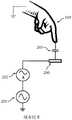
在互电容方法中,如图1中所示,在透明基板(未示出)上形成有驱动电极100和感测电极101。从电压源102向驱动电极100施加变化的电压或激励信号。然后通过在驱动电极100和感测电极101之间形成的互耦合电容器103的电容耦合在相邻的感测电极101上产生信号。电流测量单元或装置104连接到感测电极101并提供互耦合电容器103的大小的测量。当输入物体105(如手指或触笔)接近这两个电极时,它形成对驱动电极106的第一动态电容器和对感测电极107的第二动态电容器。如果输入物体接地,例如连接到人体的人手指的情况,这些动态地形成的电容的效果表现为驱动电极和感测电极之间的电容耦合量减少,以及因此由连接到感测电极101的该电流测量单元或装置104测得的信号幅度的减小。In the mutual capacitance method, as shown in FIG. 1 , driving
在自电容方法中,如图2中所示,在透明基板(未示出)上形成有驱动电极200。从电压源201向驱动电极200施加变化的电压或激励信号。电流测量装置202连接到电极200,并提供该电极对地的自电容203的大小的测量。当输入物体105靠近该电极时,它改变自电容203的值。如果输入物体接地,例如连接到人体的人手指的情况,效果是增加该电极对地的自电容203,并因此增加由连接到感测电极200的电流测量装置202测得的信号幅度。In the self-capacitance method, as shown in FIG. 2, a
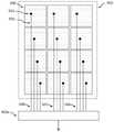
众所周知并且例如在US5,841,078(Bisset等人,1996年10月30日发布)中公开了通过以网格图案布置多个驱动电极和感测电极以形成电极阵列,互电容感测方法可用于形成触摸面板设备。图3示出可被配置为驱动电极的水平电极300和可被配置为感测电极的垂直电极301的合适图案。互电容感测方法的优点是可以检测多个同时触摸输入事件。Mutual capacitance sensing methods are well known and disclosed, for example, in US 5,841,078 (Bisset et al., issued October 30, 1996) by arranging a plurality of drive and sense electrodes in a grid pattern to form an electrode array. touch panel device. Figure 3 shows a suitable pattern of
众所周知,通过以网格图案布置多个电极以形成电极阵列,自电容感测方法可用于形成触摸面板设备。图3示出可被配置为感测电极的水平电极300和垂直电极301的合适图案。然而,这种设备的局限性在于它不能可靠地检测来自多个物体的同时触摸。It is well known that self-capacitance sensing methods can be used to form touch panel devices by arranging a plurality of electrodes in a grid pattern to form an electrode array. Figure 3 shows a suitable pattern of
另外,众所周知并且例如在US 9,250,735(Kim等人,2016年2月2日发布)中公开了通过以二维阵列布置多个电极,并且通过提供从每个电极到控制器的电连接,该自电容感测方法可被用于形成能够可靠地检测来自多个物体的同时触摸的触摸面板设备。互电容感测也可以与这种分别连接的电极的二维阵列一起使用,例如,如US 2016/0320886(Kim等人,2016年11月3日公开)中所公开的。In addition, it is well known and disclosed, for example, in US 9,250,735 (Kim et al., issued Feb. 2, 2016) that by arranging a plurality of electrodes in a two-dimensional array, and by providing electrical connections from each electrode to a controller, the automatic Capacitive sensing methods can be used to form touch panel devices that can reliably detect simultaneous touches from multiple objects. Mutual capacitance sensing can also be used with such two-dimensional arrays of separately connected electrodes, eg, as disclosed in US 2016/0320886 (Kim et al., published Nov. 3, 2016).
在许多触摸屏中,触摸面板是独立于显示器的设备,称为“单元外(out-cell)”触摸面板。触摸面板位于显示器的顶部,并且显示器产生的光穿过触摸面板,一定量的光被触摸面板吸收。在更近的实施方式中,触摸面板的一部分集成在显示器叠层内,并且触摸面板和显示器可以共用某些结构,如透明电极。这被称为“单元内(in-cell)”触摸面板。将触摸面板集成到显示器结构中旨在通过简化制造来降低成本,以及减少触摸面板独立于显示器并位于显示器叠层顶部时发生的光通量损失。In many touch screens, the touch panel is a separate device from the display, called an "out-cell" touch panel. The touch panel is located on top of the display, and the light generated by the display passes through the touch panel, and a certain amount of light is absorbed by the touch panel. In more recent embodiments, a portion of the touch panel is integrated within the display stack, and the touch panel and display may share certain structures, such as transparent electrodes. This is called an "in-cell" touch panel. Integrating the touch panel into the display structure is intended to reduce costs by simplifying manufacturing, as well as reducing the loss of light flux that occurs when the touch panel is separate from the display and on top of the display stack.
如上所述的电容测量技术传统上应用于触摸面板的局限性在于它们不能检测来自例如由木材、塑料等制成的非导电或绝缘物体的输入。具有不同于空气的介电常数的非导电物体在接近触摸面板表面时将导致测量的阵列电容改变。然而,所得信号的幅度非常小-例如,小于导电物体产生的信号的1%-并且取决于制造非导电物体的材料类型和周围环境条件。这不利地降低了触摸面板的可用性,因为它限于使用诸如手指或金属笔或触笔之类的导电输入物体的操作。特别地,用户在佩戴普通(非导电)手套时或在握住诸如塑料笔的非导电物体时不能可靠地操作触摸面板。A limitation of the traditional application of capacitive measurement techniques to touch panels as described above is that they cannot detect input from non-conductive or insulating objects, eg, made of wood, plastic, and the like. A non-conductive object with a different dielectric constant than air will cause the measured array capacitance to change as it approaches the touch panel surface. However, the magnitude of the resulting signal is very small - for example, less than 1% of the signal produced by a conductive object - and depends on the type of material from which the non-conductive object is made and the surrounding environmental conditions. This disadvantageously reduces the usability of the touch panel as it is limited to operation using conductive input objects such as fingers or metal pens or styluses. In particular, the user cannot reliably operate the touch panel while wearing ordinary (non-conductive) gloves or while holding a non-conductive object such as a plastic pen.
US 9,105,255(Brown等人,2015年8月11日发布)公开了一种互电容触摸面板,其能够检测非导电物体,并且能够区分物体是导电的还是不导电的。这是通过测量在不同耦合距离上形成的多个互电容来实现的。可以基于多个互电容的变化来确定物体的类型(导电或不导电)。多个互电容形成在行和列电极的阵列之间。US 9,105,255 (Brown et al., issued Aug. 11, 2015) discloses a mutual capacitance touch panel capable of detecting non-conducting objects and distinguishing whether the objects are conductive or non-conductive. This is achieved by measuring the multiple mutual capacitances formed over different coupling distances. The type of object (conducting or non-conducting) can be determined based on changes in multiple mutual capacitances. A plurality of mutual capacitances are formed between the arrays of row and column electrodes.
共同拥有的美国专利申请No.15/409,910公开了一种使用二维电极阵列检测非导电物体或区分导电物体和非导电物体的方法,每个电极与控制器分别连接。控制器在多个测量时间段期间测量电极组之间的互电容。在每个测量时间段中,控制器将一些电极指定为驱动电极,将一些电极指定为感测电极,并将一些电极指定为未使用电极。控制器将驱动信号施加到驱动电极,并且测量驱动电极和每个感测电极之间的耦合。Commonly owned US Patent Application No. 15/409,910 discloses a method of detecting or distinguishing between conductive objects and non-conductive objects using a two-dimensional array of electrodes, each electrode being separately connected to a controller. The controller measures the mutual capacitance between the electrode sets during a plurality of measurement time periods. During each measurement period, the controller designates some electrodes as drive electrodes, some electrodes as sense electrodes, and some electrodes as unused electrodes. The controller applies drive signals to the drive electrodes and measures the coupling between the drive electrodes and each sense electrode.
发明内容SUMMARY OF THE INVENTION
本发明涉及一种驱动电容式触摸面板的控制器及方法,其中该触摸面板包括二维电极阵列,该驱动方法允许只通过自电容感测方法来检测导电物体和非导电物体二者。本发明可以使用任何这种二维电极阵列,并且不依赖于任何特定的触摸面板结构、制造技术或电极连接方法。The present invention relates to a controller and method for driving a capacitive touch panel, wherein the touch panel includes a two-dimensional electrode array, the driving method allowing both conductive and non-conductive objects to be detected only by self-capacitance sensing methods. The present invention can use any such two-dimensional electrode array and is not dependent on any particular touch panel structure, fabrication technique, or electrode connection method.
附图说明Description of drawings
图1示出互电容触摸面板的常用实施方式。Figure 1 shows a common implementation of a mutual capacitance touch panel.
图2示出自电容触摸面板的常用实施方式。Figure 2 shows a common implementation of a self-capacitance touch panel.
图3示出可用于互电容或自电容感测的垂直电极和水平电极的常用图案。Figure 3 shows a common pattern of vertical and horizontal electrodes that can be used for mutual capacitance or self capacitance sensing.
图4示出包括与显示器集成的有源矩阵触摸传感器面板的触摸面板显示系统。4 illustrates a touch panel display system including an active matrix touch sensor panel integrated with a display.
图5示出第一层上的二维电极阵列,在第二层上与控制器相连。Figure 5 shows a two-dimensional electrode array on the first layer, connected to the controller on the second layer.
图6示出形成触摸传感器面板的二维电极阵列的另一实施例。FIG. 6 illustrates another embodiment of a two-dimensional electrode array forming a touch sensor panel.
图7示出根据本发明的实施例的自电容触摸面板的实施方式。FIG. 7 shows an implementation of a self-capacitance touch panel according to an embodiment of the present invention.
图8示出根据本发明的实施例的混合电容触摸面板的实施方式。8 illustrates an implementation of a hybrid capacitive touch panel according to an embodiment of the present invention.
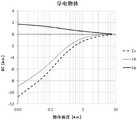
图9示出导电物体接近触摸面板表面时信号ΔCs、ΔCh和ΔCp的示例曲线图。FIG. 9 shows example graphs of signals ΔCs , ΔCh and ΔCp when a conductive object is in proximity to the touch panel surface.
图10示出非导电物体接近触摸面板表面时信号ΔCs、ΔCh和ΔCp的示例曲线图。Figure 10 shows example plots of signals ACs , ACh and ACp when a non-conductive object is in proximity to the touch panel surface.
图11示出使用本发明的实施例的触摸面板检测非导电物体的算法。11 illustrates an algorithm for detecting non-conductive objects using a touch panel of an embodiment of the present invention.
图12示出使用本发明的实施例的触摸面板检测物体的算法。12 illustrates an algorithm for detecting objects using a touch panel of an embodiment of the present invention.
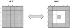
图13A示出S模式中的电极矩阵,图13B示出P模式中的相同电极矩阵。FIG. 13A shows the electrode matrix in S mode, and FIG. 13B shows the same electrode matrix in P mode.
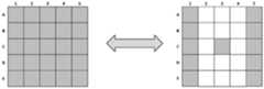
图14A和14B示出S模式和P模式中的电极的替代配置。Figures 14A and 14B show alternative configurations of electrodes in S-mode and P-mode.
图15示出如何通过寻址触摸元件的完整列来配置S模式和P模式。Figure 15 shows how to configure S-mode and P-mode by addressing a complete column of touch elements.
图16示出如何沿着面板的边长(length)扫描P模式列。Figure 16 shows how the P-mode columns are scanned along the length of the side of the panel.
图17示出驱动/感测的方法,其中已经为P模式选择了棋盘图案作为电极子集的示例。Figure 17 shows a method of driving/sensing where a checkerboard pattern has been selected for the P-mode as an example of a subset of electrodes.
图18示出触摸面板系统,其具有辅助电路以在传感器面板和控制器之间进行接口。Figure 18 shows a touch panel system with auxiliary circuitry to interface between the sensor panel and the controller.
具体实施方式Detailed ways
本发明提供一种驱动电容式触摸面板的控制器和方法,该电容式触摸面板可以用在例如触摸面板显示系统等中。图4示出这种触摸面板显示系统400的一个实施例。该系统包括连接到触摸面板控制器403的触摸传感器面板401。控制器403可以包括复用器单元404和测量/处理单元405。在另一个实施例中,复用器单元404可以与控制器403分离。控制器检测触摸传感器面板上的触摸并确定触摸的属性。该信息被提供给系统控制单元406,系统控制单元406可以包括例如处理器、存储器和显示驱动器。系统控制单元406将视觉信息输出到显示器402。显示器可以是例如LCD或OLED显示器或其他类型的显示器。系统控制单元406可以执行动作并且可以响应于控制器403检测到的触摸来修改视觉信息。The present invention provides a controller and method for driving a capacitive touch panel, which can be used in, for example, a touch panel display system or the like. FIG. 4 shows one embodiment of such a touch
本发明可包括任何二维电极阵列。The present invention may include any two-dimensional electrode array.
这里,“二维阵列”表示布置在表面上或表面附近的多个电极,使得在第一方向上存在第一数量的电极,在第二方向上存在第二数量的电极。注意,阵列可以包括在三维中彼此分离的电极,例如,如果不同的电极在触摸面板的不同层上,或者如果触摸面板表面是弯曲的。还要注意,电极可以彼此重叠。Here, "two-dimensional array" means a plurality of electrodes arranged on or near a surface such that there are a first number of electrodes in a first direction and a second number of electrodes in a second direction. Note that the array may include electrodes that are separated from each other in three dimensions, eg, if different electrodes are on different layers of the touch panel, or if the touch panel surface is curved. Also note that the electrodes can overlap each other.
图5示出形成触摸传感器面板401的二维电极阵列的一个实施例。该阵列包括形成在第一层上的十二个方块电极500,其中四个电极沿第一方向布置,三个电极沿第二方向布置。通孔501将第一层上的每个电极500连接到第二层上的连接线502。通过这种方式,每个电极500通过连接线502分别连接到控制器403a。第一列电极通过连接线504连接,第二列通过连接线505连接,第三列通过连接线506连接。FIG. 5 illustrates one embodiment of a two-dimensional electrode array forming
图6示出形成触摸传感器面板401的二维电极阵列的另一实施例。该阵列包括形成在第一层上的十二个方块电极600,其中四个电极沿第一方向布置,三个电极沿第二方向布置。每个电极600通过第一层上的导线601和类似于前一实施例的附加连接线504、505和506分别连接到控制器403a。FIG. 6 shows another embodiment of a two-dimensional electrode array forming a
本领域技术人员将清楚,可以使用许多二维电极阵列结构。还将清楚的是,这些结构中很多可以制成离散的(discrete)“单元外(out-cell)”触摸面板,其可以结合到单独的显示器上,并且这些结构中的很多可以集成在显示设备中作为“单元内(in-cell)”或“混合单元内(hybrid in-cell)”触摸面板。此外,电极阵列结构可以使用一个导电层或两个以上的导电层。类似地,电极可以设置在一层上或多于一层上。It will be apparent to those skilled in the art that many two-dimensional electrode array structures can be used. It will also be clear that many of these structures can be made into discrete "out-cell" touch panels, which can be incorporated into a separate display, and that many of these structures can be integrated in a display device as an "in-cell" or "hybrid in-cell" touch panel. In addition, the electrode array structure may use one conductive layer or two or more conductive layers. Similarly, electrodes may be provided on one layer or on more than one layer.
例如,形成图5的电极500和图6的电极600的一种方式是在透明基板上沉积并图案化由诸如ITO的材料制成的透明导电层。这可以使用标准光刻或印刷技术来完成。For example, one way to form
图5的通孔501和连接线502也可以使用标准光刻或印刷技术来形成。例如,绝缘层可以沉积在第一导电层的顶部上并且被图案化以产生用于通孔的孔,并且第二导电层可以沉积在绝缘层的顶部上。该第二导电层形成通孔501,并且可以被图案化以形成连接线502。这些技术适合于生产离散的(“单元外”)触摸面板。The
作为选择,触摸面板可以集成在显示设备内。例如,图5的电极500和图6的电极600可以通过分割液晶显示设备的VCOM层来形成。类似地,可以使用用于制造显示数据线和/或栅极线的相同分层工艺来形成通孔501和连接线502。Alternatively, the touch panel can be integrated into the display device. For example, the
用于制造合适的单元外和单元内触摸面板的结构和技术在现有技术中是众所周知的。本发明可以使用任何二维电极阵列,并且不依赖于任何特定的触摸面板结构或制造技术。Structures and techniques for fabricating suitable out-of-cell and in-cell touch panels are well known in the art. The present invention can use any two-dimensional electrode array and is not tied to any particular touch panel structure or fabrication technique.
本发明示出使用自电容驱动方法的触摸感测系统如何被配置为有效地检测非导电物体。The present invention shows how a touch sensing system using a self-capacitance driving method can be configured to efficiently detect non-conductive objects.
参考图7,图7示出由任意数量的相邻电极围绕的触摸电极200-2,其在图中由电极200-1和200-3表示。电极具有任意形状,并且以自电容配置被驱动。这通过电极共享信号源201的方式来说明,而每个电极具有独立的测量电路202-x(在该示例中为202-1,202-2和202-3)。这仅是示例性的,并且在实践中可以使用其他自电容驱动布置。在该配置中,触摸面板控制器可以测量所有自电容203-x(在该示例中为203-1,203-2和203-3)中的变化。特别地,自电容203-2的变化将被称为ΔCs。该配置将被称为S模式。Referring to Figure 7, Figure 7 shows a touch electrode 200-2 surrounded by any number of adjacent electrodes, represented in the figure by electrodes 200-1 and 200-3. The electrodes have arbitrary shapes and are driven in a self-capacitance configuration. This is illustrated by the way the electrodes share the
在替代配置中,可以向触摸电极200-2提供来自相邻电极200-1和200-3的不同驱动信号。In an alternative configuration, touch electrode 200-2 may be provided with different drive signals from adjacent electrodes 200-1 and 200-3.
在另一自电容感测配置中,可以省略测量电路202-1和202-3。在这种情况下,触摸面板控制器可以仅测量电极200-2的自电容203-2(ΔCs)的变化。可以顺序地进行不同电极或电极组的测量。In another self-capacitance sensing configuration, measurement circuits 202-1 and 202-3 may be omitted. In this case, the touch panel controller may only measure the change in the self-capacitance 203-2 (ΔCs ) of the electrode 200-2. Measurements on different electrodes or groups of electrodes can be performed sequentially.
图8示出电极200-x的第二配置,其将被称为P模式。在该配置中,由电极200-1和200-3表示的电极200-2的特定邻域中的所有电极连接到参考电位。作为示例,在图8中,参考电位被选为地,但可以选择任何其他参考电位。电极200-2保持连接到触摸面板控制器,如图7所示。在P模式中,触摸面板控制器测量电极200-2的电容203-2的变化。但是在这种情况下,电容203-2的变化不仅由电极200-2的自电容的变化给出,而且电极200-2和其接地的邻居之间的“赝互”电容的变化也有一定的贡献。因此,电极200-2的该混合测量的电容变化ΔCh将具有值ΔCh=(ΔCs+ΔCp),其中ΔCs是自电容分量的变化,ΔCp是赝互电容分量的变化。Figure 8 shows a second configuration of electrodes 200-x, which will be referred to as P-mode. In this configuration, all electrodes in a particular neighborhood of electrode 200-2, represented by electrodes 200-1 and 200-3, are connected to a reference potential. As an example, in Figure 8, the reference potential is chosen to be ground, but any other reference potential may be chosen. Electrode 200-2 remains connected to the touch panel controller as shown in FIG. In the P-mode, the touch panel controller measures the change in capacitance 203-2 of electrode 200-2. But in this case, the change in capacitance 203-2 is given not only by the change in the self-capacitance of electrode 200-2, but also by the change in the "pseudo-mutual" capacitance between electrode 200-2 and its grounded neighbor contribute. Thus, this mixed measured capacitance change ΔCh of electrode 200 - 2 will have the value ΔCh = (ΔCs + ΔCp ), where ΔCs is the change in the self-capacitance component and ΔCp is the change in the pseudo-mutual capacitance component.
电极200-2相对于其接地邻居的赝互电容以自电容模式被感测,即,被驱动和感测电极仅为200-2。这与互电容测量不同,在互电容测量中通过驱动一个电极并感测另一个电极来测量一对电极之间的电容变化。The pseudo mutual capacitance of electrode 200-2 relative to its ground neighbor is sensed in a self-capacitance mode, ie, the driven and sensed electrodes are only 200-2. This differs from mutual capacitance measurements, where the change in capacitance between a pair of electrodes is measured by driving one electrode and sensing the other.
在本发明的示例性实施例中,触摸面板控制器首先在S模式中测量电极200-x,获得电极200-2的ΔCs。接下来,触摸面板控制器在P模式中测量电极200-x,获得电极200-2的ΔCh。一旦进行了这两个测量,控制器就可以从后一值ΔCh中减去第一值ΔCs,以隔离电极200-2的赝互电容分量ΔCp。然后可以对面板中的所有触摸电极重复该过程。In an exemplary embodiment of the present invention, the touch panel controller first measures the electrode 200-x in theS -mode to obtain the ΔCs of the electrode 200-2. Next, the touch panel controller measures electrode 200-x in P-mode to obtain ΔCh for electrode 200-2. Once these two measurements have been made, the controller can subtract the first value ACs from the latter value ACh to isolate the pseudo-mutual capacitance component ACp of the electrode 200 - 2 . The process can then be repeated for all touch electrodes in the panel.
图9示出导电物体接近触摸面板表面时信号ΔCs、ΔCh和ΔCp的示例性曲线图。如所预期的,在S模式中测得的自电容信号ΔCs是负的,表明导电物体减小了电极200-2的自电容。赝互电容ΔCp与自电容信号ΔCs相比较小,并且与ΔCs的符号相反。FIG. 9 shows exemplary graphs of signals ΔCs , ΔCh and ΔCp when a conductive object is in proximity to the touch panel surface. As expected, the measured self-capacitance signal ΔCs inS -mode is negative, indicating that the conductive object reduces the self-capacitance of electrode 200-2. The pseudo-mutual capacitance ΔCp is small compared to the self-capacitance signal ΔCs and has an opposite sign to ΔCs .
图10示出非导电物体接近触摸面板表面时信号ΔCs、ΔCh和ΔCp的示例性曲线图。轴刻度与图9相同。来自S模式的自电容信号ΔCs仍然是负的,并且比导电物体的小得多;这说明了用于检测非导电物体的传统自电容方案的主要困难。当物体远离触摸面板的表面时,赝互电容ΔCp小且为正;但随着物体接近表面,ΔCp变为负,其幅度稳定增长。特别地,对于足够靠近表面的物体,ΔCp远大于ΔCs。对于常用的触摸面板,ΔCs低于检测阈值,但ΔCp远高于检测阈值。因此,该结果显示了可以如何通过使用所提出的方法检测非导电探针。10 shows exemplary graphs of signals ACs , ACh and ACp when a non-conductive object is in proximity to the touch panel surface. The axis scales are the same as in Figure 9. The self-capacitance signal ΔCs from theS -mode is still negative and much smaller than that of conducting objects; this illustrates the main difficulty of conventional self-capacitance schemes for detecting non-conducting objects. When the object is far from the surface of the touch panel, the pseudo mutual capacitance ΔCp is small and positive; but as the object approaches the surface, ΔCp becomes negative and its magnitude increases steadily. In particular, for objects close enough to the surface, ΔCp is much larger than ΔCs . For commonly used touch panels, ΔCs is below the detection threshold, but ΔCp is much higher than the detection threshold. Therefore, this result shows how non-conductive probes can be detected by using the proposed method.
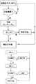
在图11中示出使用本发明的用于检测非导电物体的算法。首先,测量信号ΔCs和ΔCh。如果通过ΔCs或ΔCh检测到触摸,则计算ΔCp。如果ΔCp为正,则物体是导电的;否则(ΔCp为负),则物体不导电。An algorithm for detecting non-conductive objects using the present invention is shown in FIG. 11 . First, the signals ΔCs and ΔCh are measured. If a touch is detected byΔCs orΔCh , thenΔCp is calculated. If ΔCp is positive, the object is conductive; otherwise (ΔCp is negative), the object is not conductive.
图12中给出的另一算法利用如下常见事实:对于自电容感测,非导电物体产生低于检测阈值的信号ΔCs。因此,可以认为如果在测量ΔCs时没有检测到物体,则以ΔCh检测到的任何物体都是不导电的。Another algorithm presented in Figure 12 exploits the common fact that for self-capacitance sensing, non-conductive objects produce a signalΔCs below the detection threshold. Therefore, it can be considered that any object detected with ΔCh is non-conductive if no object is detected when ΔCs is measured.
对于一些触摸面板和/或触摸面板控制器,实现图11和图12的算法可能由于需要进行多次测量而很慢。克服这种额外计算负担的一种可能方式是例如几个触摸周期中只有一个周期进行ΔCh和ΔCp的测量,所有其他周期执行传统的自电容测量周期。For some touch panels and/or touch panel controllers, implementing the algorithms of FIGS. 11 and 12 may be slow due to the need to make multiple measurements. One possible way to overcome this additional computational burden is for example that only one of several touch cycles performs the measurements of ΔCh and ΔCp , all other cycles perform the traditional self-capacitance measurement cycle.
图13A示出S模式中的电极矩阵,图13B示出根据本发明实施例的P模式中的相同电极矩阵。阴影电极以自电容测量,而空白电极接地。电极C3是要计算ΔCp的电极。FIG. 13A shows an electrode matrix in S mode, and FIG. 13B shows the same electrode matrix in P mode according to an embodiment of the present invention. Shaded electrodes are measured with self-capacitance, while blank electrodes are grounded. Electrode C3 is the electrode for which ΔCp is to be calculated.
在图13A和图13B的示例中,已选择最近的两级邻居作为电极C3的邻域。但是该邻域可以选择为更大或更小,并且不需要是对称的,如图14A和图14B中的示例所示。In the example of Figures 13A and 13B, the nearest two-level neighbor has been selected as the neighbor of electrode C3. But the neighborhood can be chosen to be larger or smaller, and need not be symmetric, as shown in the examples in Figures 14A and 14B.
实际上,针对面板中的每个触摸元件分别测量ΔCp可能太慢或太麻烦。在一些实施例中,在每个测量周期中驱动/感测全部行/列的触摸元件。图15示出如何通过寻址触摸元件的完整列来配置S模式和P模式。首先,触摸面板控制器以S模式配置面板,以自电容模式驱动面板上的所有电极,并测量面板上每个触摸电极的ΔCs。可以同时测量电极,或者可以顺序测量不同组的电极(例如行/列)。然后,控制器通过驱动/感测触摸电极的完整的列来实现P模式。为了针对整个触摸面板扫描ΔCp,可以沿着面板的边长扫描P模式列,如图16中所示。等效实施例寻址整行的触摸元件。In practice, it may be too slow or cumbersome to measure ΔCp separately for each touch element in the panel. In some embodiments, all rows/columns of touch elements are driven/sensed in each measurement cycle. Figure 15 shows how S-mode and P-mode can be configured by addressing a complete column of touch elements. First, the touch panel controller configures the panel inS -mode, drives all electrodes on the panel in self-capacitance mode, and measures ΔCs for each touch electrode on the panel. The electrodes can be measured simultaneously, or different groups of electrodes (eg, rows/columns) can be measured sequentially. The controller then implements the P-mode by driving/sensing the complete column of touch electrodes. To scan ΔCp for the entire touch panel, the P-mode column can be scanned along the side length of the panel, as shown in FIG. 16 . Equivalent embodiments address an entire row of touch elements.
在一些实施例中,在S模式中在每个测量周期驱动/感测整个触摸面板。在这种情况下,可以通过在第一周期仅驱动/感测触摸电极的子集,然后在第二周期驱动/感测互补子集来实现P模式。该过程在图17中示出,其中已经为P模式选择了棋盘图案作为电极子集的示例。In some embodiments, the entire touch panel is driven/sensed every measurement cycle in S-mode. In this case, the P-mode can be achieved by driving/sensing only a subset of the touch electrodes in the first period and then driving/sensing the complementary subset in the second period. This process is illustrated in Figure 17, where a checkerboard pattern has been selected for the P-mode as an example of a subset of electrodes.
其他实施例具有与上述操作模式不同的操作模式,但是本领域技术人员可以使本发明的方法适用于这些操作模式。Other embodiments have different modes of operation than those described above, but those skilled in the art can adapt the method of the present invention to these modes of operation.
根据上面公开的思想,在P模式中,许多触摸电极接地,而其余触摸电极被驱动/感测。一些触摸面板控制器可以在内部配置以实现该功能分配。一些其他触摸面板控制器可能需要硬件修改的固件以实现P模式图案。作为选择,如图18中所示,可以将辅助电路1600添加到触摸面板系统400以在传感器面板401和控制器403之间进行接口,以便执行给定的P模式图案所需的必要触摸元件切换。According to the ideas disclosed above, in P-mode, many touch electrodes are grounded while the rest are driven/sensed. Some touch panel controllers can be internally configured to implement this function assignment. Some other touch panel controllers may require hardware modified firmware to implement the P-mode pattern. Alternatively, as shown in Figure 18,
因此,本发明的一个方面是一种触摸面板,其配置为基于电极电位测量来区分导电物体和非导电物体。在示例性实施例中,触摸面板包括:以电极阵列布置的多个电极,其中所述多个电极包括多个触摸面板元件;控制器,其配置为当所述电极阵列的电极被充电或放电到特定电压时测量流入或流出所述电极的电荷,并且配置为将所述电极阵列中的相邻电极连接到参考电位和电压波形;以及感测系统,其在以所述电压波形驱动一组相邻电极的同时对流入或流出所述电极的电荷进行第一次测量,并且在该组相邻电极连接到所述参考电位的同时进行第二次测量。所述控制器还配置为基于两次测量的比较来区分导电物体和非导电物体。所述触摸面板可以单独地或组合地包括以下特征中的一个或多个。Accordingly, one aspect of the present invention is a touch panel configured to distinguish between conductive objects and non-conductive objects based on electrode potential measurements. In an exemplary embodiment, a touch panel includes: a plurality of electrodes arranged in an electrode array, wherein the plurality of electrodes includes a plurality of touch panel elements; and a controller configured to charge or discharge electrodes of the electrode array when the electrodes are charged or discharged. measuring the charge flowing into or out of the electrodes to a specific voltage, and configured to connect adjacent electrodes in the electrode array to a reference potential and a voltage waveform; and a sensing system that drives a group of electrodes with the voltage waveform A first measurement of charge flowing into or out of said electrodes is made while adjacent electrodes, and a second measurement is made while the set of adjacent electrodes is connected to the reference potential. The controller is also configured to distinguish between conductive objects and non-conductive objects based on the comparison of the two measurements. The touch panel may include one or more of the following features, alone or in combination.
在所述触摸面板的示例性实施例中,所述控制器配置为在给定的测量周期中驱动和/或感测小于所述触摸面板中的触摸元件的总数的多个触摸元件。In an exemplary embodiment of the touch panel, the controller is configured to drive and/or sense a plurality of touch elements less than the total number of touch elements in the touch panel in a given measurement period.
在所述触摸面板的示例性实施例中,所述控制器配置为驱动和/或感测触摸面板元件的列或行中的一个。In an exemplary embodiment of the touch panel, the controller is configured to drive and/or sense one of the columns or rows of touch panel elements.
在所述触摸面板的示例性实施例中,在连续的测量周期中在所述触摸面板上扫描被驱动和/或被感测的电极的图案。In an exemplary embodiment of the touch panel, the pattern of driven and/or sensed electrodes is scanned across the touch panel in successive measurement cycles.
在所述触摸面板的示例性实施例中,所述控制器配置为在给定的测量周期中驱动和/或感测所述触摸面板中的所有触摸面板元件。In an exemplary embodiment of the touch panel, the controller is configured to drive and/or sense all touch panel elements in the touch panel during a given measurement period.
在所述触摸面板的示例性实施例中,在连续的测量周期中被驱动和/或被感测的电极的图案被切换到互补图案。In an exemplary embodiment of the touch panel, the patterns of electrodes that are driven and/or sensed in successive measurement cycles are switched to complementary patterns.
在所述触摸面板的示例性实施例中,在所述控制器外部具有电路,该电路选择哪些电极连接到所述电压波形以及与所述电压波形的连接的定时,并且选择哪些电极连接到参考电位以及与所述参考电位的连接的定时。In an exemplary embodiment of the touch panel, there is circuitry external to the controller that selects which electrodes are connected to the voltage waveform and the timing of connections to the voltage waveform, and which electrodes are connected to a reference potential and timing of the connection to the reference potential.
在所述触摸面板的示例性实施例中,所述控制器包括复用器。In an exemplary embodiment of the touch panel, the controller includes a multiplexer.
本发明的另一方面是使用触摸面板感测物体的方法,其区分导电物体与非导电物体。在示例性实施例中,所述感测方法包括以下步骤:将多个电极布置成电极阵列,其中所述多个电极包括多个触摸面板元件;当所述电极阵列的电极被充电或放电到特定电压时测量流入或流出所述电极的电荷,并将所述电极阵列中的相邻电极连接到参考电位和电压波形;在以所述电压波形驱动一组相邻电极的同时对流入或流出所述电极的电荷进行第一次测量;在该组相邻电极连接到所述参考电位的同时进行第二次测量;以及基于两次测量的比较来区分导电物体和非导电物体。所述感测方法可以单独地或组合地包括以下特征中的一个或多个。Another aspect of the present invention is a method of sensing objects using a touch panel that distinguishes conductive objects from non-conductive objects. In an exemplary embodiment, the sensing method includes the steps of: arranging a plurality of electrodes into an electrode array, wherein the plurality of electrodes includes a plurality of touch panel elements; when the electrodes of the electrode array are charged or discharged to Measure the charge flowing into or out of the electrodes at a specific voltage, and connect adjacent electrodes in the electrode array to a reference potential and a voltage waveform; control the inflow or outflow while driving a set of adjacent electrodes with the voltage waveform The charge of the electrodes is measured a first time; a second measurement is made while the set of adjacent electrodes is connected to the reference potential; and conductive objects are distinguished from non-conductive objects based on a comparison of the two measurements. The sensing method may include one or more of the following features, alone or in combination.
在所述感测方法的示例性实施例中,所述感测方法还包括在给定的测量周期中驱动和/或感测小于所述触摸面板中的触摸元件的总数的多个触摸元件。In an exemplary embodiment of the sensing method, the sensing method further comprises driving and/or sensing a plurality of touch elements less than the total number of touch elements in the touch panel in a given measurement period.
在所述感测方法的示例性实施例中,所述控制器被配置为驱动和/或感测触摸面板元件的列或行中的一个。In an exemplary embodiment of the sensing method, the controller is configured to drive and/or sense one of the columns or rows of touch panel elements.
在所述感测方法的示例性实施例中,在连续的测量周期中在所述触摸面板上扫描被驱动和/或被感测的电极的图案。In an exemplary embodiment of the sensing method, a pattern of driven and/or sensed electrodes is scanned on the touch panel in successive measurement cycles.
在所述感测方法的示例性实施例中,所述感测方法还包括在给定的测量周期中驱动和/或感测所述触摸面板中的所有触摸面板元件。In an exemplary embodiment of the sensing method, the sensing method further comprises driving and/or sensing all touch panel elements in the touch panel in a given measurement period.
在所述感测方法的示例性实施例中,在连续的测量周期中被驱动和/或被感测的电极的图案被切换到互补图案。In an exemplary embodiment of the sensing method, the patterns of electrodes driven and/or sensed in successive measurement cycles are switched to complementary patterns.
在所述感测方法的示例性实施例中,所述感测方法还包括使用所述控制器外部的电路选择哪些电极连接到所述电压波形以及与所述电压波形的连接的定时,并且选择哪些电极连接到参考电位以及与所述参考电位的连接的定时。In an exemplary embodiment of the sensing method, the sensing method further includes selecting, using circuitry external to the controller, which electrodes are connected to the voltage waveform and the timing of connections to the voltage waveform, and selecting Which electrodes are connected to a reference potential and the timing of the connection to said reference potential.
在所述感测方法的示例性实施例中,向所述电极和所述相邻电极提供不同的驱动电压。In an exemplary embodiment of the sensing method, different driving voltages are provided to the electrodes and the adjacent electrodes.
在所述感测方法的示例性实施例中,所述感测方法还包括以S模式操作所述触摸面板,在所述S模式中测量所述电极和所述相邻电极的自电容。In an exemplary embodiment of the sensing method, the sensing method further includes operating the touch panel in an S-mode in which self-capacitances of the electrodes and the adjacent electrodes are measured.
在所述感测方法的示例性实施例中,所述感测方法还包括以P模式操作所述触摸面板,所述P模式包括测量所述电极和相邻的接地电极之间的电容变化。In an exemplary embodiment of the sensing method, the sensing method further includes operating the touch panel in a P-mode including measuring a change in capacitance between the electrode and an adjacent ground electrode.
在所述感测方法的示例性实施例中,所述第一次测量在S模式中进行,并且所述第二次测量在P模式中进行。In an exemplary embodiment of the sensing method, the first measurement is performed in S-mode and the second measurement is performed in P-mode.
尽管已经关于某个或某些实施例示出和描述了本发明,但是本领域技术人员在阅读并理解了本说明书和附图时可以想到等同的替换和修改。特别是关于由上述元件(部件、组件、设备、组合物等)执行的各种功能,除非另有说明,否则用于描述这些元件的术语(包括对“装置”的引用)旨在对应于执行所描述的元件的指定功能的任何元件(即,功能上等同),尽管在结构上不等同于在本发明的示例性的一个或多个实施例中执行功能的所公开的结构。另外,虽然上面仅针对若干实施例中的一个或多个描述了本发明的特定特征,但是如果对于任何给定的或特定的实施例可以是期望的和有利的,这样的特征可以与其他实施例的一个或多个其他特征组合。While the invention has been shown and described with respect to one or certain embodiments, equivalent alternatives and modifications will occur to those skilled in the art upon reading and understanding this specification and the accompanying drawings. Particularly with regard to the various functions performed by the above-described elements (components, assemblies, devices, compositions, etc.), unless otherwise stated, the terms used to describe these elements (including references to "means") are intended to correspond to performing Any element that is functionally specified (ie, functionally equivalent) of the described elements, although not structurally equivalent to the disclosed structure performing the function in the exemplary embodiment or embodiments of the invention. Additionally, although specific features of the invention have been described above with respect to only one or more of several embodiments, such features may be implemented with others if desired and advantageous for any given or specific embodiment. One or more other feature combinations of the example.
工业实用性Industrial Applicability
本发明适合于改进电容式触摸面板设备在各种背景下的操作。这种电容式触摸面板设备可以应用于一系列消费电子产品中,例如包括移动电话、平板电脑、膝上和桌上电脑、电子书阅读器和数字标牌产品。The present invention is suitable for improving the operation of capacitive touch panel devices in a variety of contexts. Such capacitive touch panel devices can be used in a range of consumer electronic products including, for example, mobile phones, tablet computers, laptop and desktop computers, e-book readers and digital signage products.
Claims (20)
Applications Claiming Priority (2)
| Application Number | Priority Date | Filing Date | Title |
|---|---|---|---|
| US15/782,964 | 2017-10-13 | ||
| US15/782,964US10528178B2 (en) | 2017-10-13 | 2017-10-13 | Capacitive touch sensing with conductivity type determination |
Publications (2)
| Publication Number | Publication Date |
|---|---|
| CN109669585A CN109669585A (en) | 2019-04-23 |
| CN109669585Btrue CN109669585B (en) | 2022-05-06 |
Family
ID=66095709
Family Applications (1)
| Application Number | Title | Priority Date | Filing Date |
|---|---|---|---|
| CN201811124865.3AActiveCN109669585B (en) | 2017-10-13 | 2018-09-26 | Capacitive touch sensing with conductivity type determination |
Country Status (2)
| Country | Link |
|---|---|
| US (1) | US10528178B2 (en) |
| CN (1) | CN109669585B (en) |
Families Citing this family (3)
| Publication number | Priority date | Publication date | Assignee | Title |
|---|---|---|---|---|
| CN113970986B (en)* | 2020-07-23 | 2024-04-12 | 乐金显示有限公司 | Touch display device, touch circuit and touch driving method thereof |
| KR20230022311A (en)* | 2021-08-05 | 2023-02-15 | 삼성디스플레이 주식회사 | Display device and method of measuring skin moisture using the same |
| CN114684684B (en)* | 2022-04-24 | 2023-12-29 | 深圳市呤云科技有限公司 | Trigger detection method and equipment for virtual elevator keys and elevator control panel |
Citations (6)
| Publication number | Priority date | Publication date | Assignee | Title |
|---|---|---|---|---|
| CN104461200A (en)* | 2014-12-05 | 2015-03-25 | 深圳市华星光电技术有限公司 | Self-capacitance touch panel and conducting layer structure thereof |
| CN105373274A (en)* | 2014-08-26 | 2016-03-02 | 乐金显示有限公司 | Touch panel and method of operating the same |
| CN105700758A (en)* | 2014-12-15 | 2016-06-22 | 三星显示有限公司 | Touch sensor device |
| CN105814525A (en)* | 2013-12-20 | 2016-07-27 | 夏普株式会社 | A discriminative capacitive touch panel |
| CN106886345A (en)* | 2015-12-16 | 2017-06-23 | 盐光股份有限公司 | Capacitive sensing device and method for detecting conductive foreign matters on same |
| US9746507B1 (en)* | 2013-10-07 | 2017-08-29 | Cypress Semiconductor Corporation | Detect and differentiate touches from different size conductive objects on a capacitive button |
Family Cites Families (25)
| Publication number | Priority date | Publication date | Assignee | Title |
|---|---|---|---|---|
| DE69324067T2 (en) | 1992-06-08 | 1999-07-15 | Synaptics Inc | Object position detector |
| KR100595922B1 (en) | 1998-01-26 | 2006-07-05 | 웨인 웨스터만 | Method and apparatus for integrating manual input |
| US8619055B2 (en) | 2008-04-14 | 2013-12-31 | Microsoft Corporation | Active matrix touch sensing |
| US8508495B2 (en) | 2008-07-03 | 2013-08-13 | Apple Inc. | Display with dual-function capacitive elements |
| US8760412B2 (en) | 2009-02-02 | 2014-06-24 | Apple Inc. | Dual configuration for display data lines |
| KR101144724B1 (en) | 2009-12-17 | 2012-05-24 | 이성호 | Touch cell structure of touch panel |
| TWI433005B (en) | 2010-06-29 | 2014-04-01 | Novatek Microelectronics Corp | Driving method, driving device and touch sensible display device using the same |
| US8599165B2 (en)* | 2010-08-16 | 2013-12-03 | Perceptive Pixel Inc. | Force and true capacitive touch measurement techniques for capacitive touch sensors |
| TWI441065B (en)* | 2010-11-03 | 2014-06-11 | Elan Microelectronics Corp | A Capacitive Touch Element for Identifying Conductor and Non - Conductor and Its Method of Discrimination |
| CN102650916B (en) | 2011-02-25 | 2014-11-26 | 乐金显示有限公司 | Touch sensor integrated display device |
| JP5960293B2 (en) | 2012-02-27 | 2016-08-02 | 熊光 蔡 | Display device and touch detection method thereof |
| KR102014276B1 (en) | 2012-11-12 | 2019-08-26 | 엘지디스플레이 주식회사 | Display device and driving method thereof |
| US20150049044A1 (en)* | 2013-08-16 | 2015-02-19 | Apple Inc. | Touch panel electrode structure |
| KR102271637B1 (en)* | 2013-09-27 | 2021-07-02 | 센셀, 인크. | Resistive touch sensor system and method |
| US9448675B2 (en) | 2014-04-29 | 2016-09-20 | Synaptics Incorporated | Input sensing using a gate select line of a display device |
| US20170102826A1 (en) | 2014-06-30 | 2017-04-13 | Sharp Kabushiki Kaisha | Touch panel system and electronic equipment |
| CN104461198B (en) | 2014-12-03 | 2017-07-07 | 深圳市华星光电技术有限公司 | A kind of touch base plate and terminal |
| EP3089002B1 (en) | 2015-04-30 | 2021-09-08 | LG Display Co., Ltd. | Touch sensor integrated type display device |
| TWI588694B (en) | 2015-06-12 | 2017-06-21 | 群創光電股份有限公司 | Touch display device |
| WO2017056900A1 (en) | 2015-10-01 | 2017-04-06 | シャープ株式会社 | Capacitance detection method, position detection method, touch panel controller, and electronic device |
| GB2542854A (en) | 2015-10-02 | 2017-04-05 | Sharp Kk | Integrated active matrix touch panel |
| US9753575B2 (en) | 2015-11-18 | 2017-09-05 | Himax Technologies Limited | In-cell touch screen and a controller adapted thereto |
| TWI581152B (en) | 2016-01-20 | 2017-05-01 | Intelligent touch touch device | |
| US10436733B2 (en)* | 2016-03-11 | 2019-10-08 | Hemy8 Sa | Method of measuring capacitance of row and column electrodes of capacitive imaging device |
| US10216972B2 (en)* | 2017-01-13 | 2019-02-26 | Synaptics Incorporated | Pixel architecture and driving scheme for biometric sensing |
- 2017
- 2017-10-13USUS15/782,964patent/US10528178B2/enactiveActive
- 2018
- 2018-09-26CNCN201811124865.3Apatent/CN109669585B/enactiveActive
Patent Citations (6)
| Publication number | Priority date | Publication date | Assignee | Title |
|---|---|---|---|---|
| US9746507B1 (en)* | 2013-10-07 | 2017-08-29 | Cypress Semiconductor Corporation | Detect and differentiate touches from different size conductive objects on a capacitive button |
| CN105814525A (en)* | 2013-12-20 | 2016-07-27 | 夏普株式会社 | A discriminative capacitive touch panel |
| CN105373274A (en)* | 2014-08-26 | 2016-03-02 | 乐金显示有限公司 | Touch panel and method of operating the same |
| CN104461200A (en)* | 2014-12-05 | 2015-03-25 | 深圳市华星光电技术有限公司 | Self-capacitance touch panel and conducting layer structure thereof |
| CN105700758A (en)* | 2014-12-15 | 2016-06-22 | 三星显示有限公司 | Touch sensor device |
| CN106886345A (en)* | 2015-12-16 | 2017-06-23 | 盐光股份有限公司 | Capacitive sensing device and method for detecting conductive foreign matters on same |
Also Published As
| Publication number | Publication date |
|---|---|
| CN109669585A (en) | 2019-04-23 |
| US10528178B2 (en) | 2020-01-07 |
| US20190114019A1 (en) | 2019-04-18 |
Similar Documents
| Publication | Publication Date | Title |
|---|---|---|
| US10402022B2 (en) | Sensor array with edge pattern | |
| US8072429B2 (en) | Multi-axial touch-sensor device with multi-touch resolution | |
| US9846499B2 (en) | Touch panel and touch detection circuit | |
| CN105637458B (en) | Single layer sensor pattern | |
| CN102576260B (en) | Input device based on voltage gradient | |
| US9405408B2 (en) | Trace pattern for touch-sensing application | |
| TWI469022B (en) | Capacitive touchscreen system and method for detecting touch on capacitive touchscreen system | |
| US20180203540A1 (en) | Discriminative controller and driving method for touch panel with array electrodes | |
| US20120044095A1 (en) | Capacitive-matrix keyboard with multiple touch detection | |
| US20160011690A1 (en) | Single Layer Sensor Pattern | |
| TWI541712B (en) | Touch screen, touch panel, and driving method thereof | |
| JP2009122969A (en) | Screen input type image display device | |
| TW201023012A (en) | Capacitive touch sensors | |
| CN102880338A (en) | Touch display device | |
| CN109669568B (en) | Active matrix touch panel with narrow bezel | |
| CN103777828A (en) | Touch panel device capable of recombining sensing points and sensing method | |
| US20150378498A1 (en) | Hybrid capacitive sensor device | |
| US11494037B2 (en) | Excitation voltages for touch sensors | |
| CN109669585B (en) | Capacitive touch sensing with conductivity type determination | |
| US11941211B2 (en) | Balanced mutual capacitance systems and methods | |
| JP5832772B2 (en) | Touch panel, touch panel system, and electronic device | |
| US20130016051A1 (en) | Touch Panel Device Having a Divided ITO layer for Reducing Loading | |
| TWI658384B (en) | Touch panel and touch detection circuit |
Legal Events
| Date | Code | Title | Description |
|---|---|---|---|
| PB01 | Publication | ||
| PB01 | Publication | ||
| SE01 | Entry into force of request for substantive examination | ||
| SE01 | Entry into force of request for substantive examination | ||
| GR01 | Patent grant | ||
| GR01 | Patent grant |