CN109658661B - A kind of supervision system and its realization method - Google Patents
A kind of supervision system and its realization methodDownload PDFInfo
- Publication number
- CN109658661B CN109658661BCN201811501197.1ACN201811501197ACN109658661BCN 109658661 BCN109658661 BCN 109658661BCN 201811501197 ACN201811501197 ACN 201811501197ACN 109658661 BCN109658661 BCN 109658661B
- Authority
- CN
- China
- Prior art keywords
- temperature
- module
- field effect
- granary
- humidity
- Prior art date
- Legal status (The legal status is an assumption and is not a legal conclusion. Google has not performed a legal analysis and makes no representation as to the accuracy of the status listed.)
- Active
Links
Images

Classifications
- G—PHYSICS
- G08—SIGNALLING
- G08B—SIGNALLING OR CALLING SYSTEMS; ORDER TELEGRAPHS; ALARM SYSTEMS
- G08B19/00—Alarms responsive to two or more different undesired or abnormal conditions, e.g. burglary and fire, abnormal temperature and abnormal rate of flow
- G—PHYSICS
- G06—COMPUTING OR CALCULATING; COUNTING
- G06Q—INFORMATION AND COMMUNICATION TECHNOLOGY [ICT] SPECIALLY ADAPTED FOR ADMINISTRATIVE, COMMERCIAL, FINANCIAL, MANAGERIAL OR SUPERVISORY PURPOSES; SYSTEMS OR METHODS SPECIALLY ADAPTED FOR ADMINISTRATIVE, COMMERCIAL, FINANCIAL, MANAGERIAL OR SUPERVISORY PURPOSES, NOT OTHERWISE PROVIDED FOR
- G06Q10/00—Administration; Management
- G06Q10/06—Resources, workflows, human or project management; Enterprise or organisation planning; Enterprise or organisation modelling
- G06Q10/063—Operations research, analysis or management
- G06Q10/0639—Performance analysis of employees; Performance analysis of enterprise or organisation operations
- G06Q10/06395—Quality analysis or management
- G—PHYSICS
- G08—SIGNALLING
- G08B—SIGNALLING OR CALLING SYSTEMS; ORDER TELEGRAPHS; ALARM SYSTEMS
- G08B5/00—Visible signalling systems, e.g. personal calling systems, remote indication of seats occupied
- G08B5/22—Visible signalling systems, e.g. personal calling systems, remote indication of seats occupied using electric transmission; using electromagnetic transmission
- G08B5/36—Visible signalling systems, e.g. personal calling systems, remote indication of seats occupied using electric transmission; using electromagnetic transmission using visible light sources
- H—ELECTRICITY
- H02—GENERATION; CONVERSION OR DISTRIBUTION OF ELECTRIC POWER
- H02J—CIRCUIT ARRANGEMENTS OR SYSTEMS FOR SUPPLYING OR DISTRIBUTING ELECTRIC POWER; SYSTEMS FOR STORING ELECTRIC ENERGY
- H02J7/00—Circuit arrangements for charging or depolarising batteries or for supplying loads from batteries
- H02J7/0047—Circuit arrangements for charging or depolarising batteries or for supplying loads from batteries with monitoring or indicating devices or circuits
- H—ELECTRICITY
- H02—GENERATION; CONVERSION OR DISTRIBUTION OF ELECTRIC POWER
- H02J—CIRCUIT ARRANGEMENTS OR SYSTEMS FOR SUPPLYING OR DISTRIBUTING ELECTRIC POWER; SYSTEMS FOR STORING ELECTRIC ENERGY
- H02J7/00—Circuit arrangements for charging or depolarising batteries or for supplying loads from batteries
- H02J7/0068—Battery or charger load switching, e.g. concurrent charging and load supply
Landscapes
- Business, Economics & Management (AREA)
- Engineering & Computer Science (AREA)
- Human Resources & Organizations (AREA)
- Physics & Mathematics (AREA)
- General Physics & Mathematics (AREA)
- Strategic Management (AREA)
- Educational Administration (AREA)
- Economics (AREA)
- Entrepreneurship & Innovation (AREA)
- Power Engineering (AREA)
- Development Economics (AREA)
- Operations Research (AREA)
- Marketing (AREA)
- Quality & Reliability (AREA)
- Tourism & Hospitality (AREA)
- General Business, Economics & Management (AREA)
- Theoretical Computer Science (AREA)
- Game Theory and Decision Science (AREA)
- Electromagnetism (AREA)
- Charge And Discharge Circuits For Batteries Or The Like (AREA)
- Arrangements For Transmission Of Measured Signals (AREA)
Abstract
Translated fromChinese
Description
Translated fromChinese技术领域technical field
本发明属于粮仓安全的技术领域,具体地讲是涉及粮仓的一种监管系统及其实现方法。The invention belongs to the technical field of granary safety, and in particular relates to a supervision system of a granary and a realization method thereof.
背景技术Background technique
众所周知,粮食储藏过程中,容易受温度、湿度及其它因素的影响,可能出现发热、霉变、虫害滋生等问题。为了减少粮食储藏过程中的损失,保障粮食的品质和质量,粮仓监控管理系统根据末端节点的传感装置监测上传的粮仓中粮食的温度与湿度的具体情况采取相应措施,进行降温、排湿、或翻仓处理。目前,粮仓监控管理系统:根据末端节点的传感装置上传的温度与湿度的具体情况,需降温和/或排湿时可以做到自动完成,但需翻仓时必须有人工参与,当翻仓的工作人员责任心不强,可能少翻,甚至不翻,现没有自动检测手段监管翻仓质量,除非现场有监管翻仓质量的管理人员。As we all know, in the process of grain storage, it is easy to be affected by temperature, humidity and other factors, and problems such as fever, mildew, and insect breeding may occur. In order to reduce the loss in the process of grain storage and ensure the quality and quality of the grain, the granary monitoring and management system takes corresponding measures according to the specific conditions of the temperature and humidity of the grain in the granary that are monitored and uploaded by the sensor device of the end node, and conducts cooling, dehumidification, or restocking. At present, the granary monitoring and management system: according to the specific conditions of the temperature and humidity uploaded by the sensor device of the end node, it can be done automatically when cooling and/or dehumidification is required, but manual participation is required when the warehouse needs to be turned over. There is no automatic detection method to supervise the quality of warehouse turnover, unless there are managers on site to supervise the quality of warehouse turnover.
众所周知,粮仓监控管理系统中末端用于防盗的传感装置节点,一般为人体红外传感器和/或摄像头,一旦他人突破人体红外传感器和摄像头防线,就有可能把粮食盗走。且众所周知,粮食储藏多数采用堆积式,粮食堆积量减少和/或堆积的粮食垮塌均会引起粮仓内压力变化。偷盗时,粮食堆积量就会减少,甚至引起堆积的粮食垮塌。目前:在防盗期间,没有粮仓监控管理系统末端节点为堆积式粮仓内压力变化的传感装置进行辅助防盗。As we all know, the sensor device nodes used for anti-theft at the end of the granary monitoring and management system are generally human infrared sensors and/or cameras. Once others break through the defense line of human infrared sensors and cameras, it is possible to steal the grain. And it is well known that most of the grain storage adopts the accumulation type, and the reduction of the grain accumulation and/or the collapse of the accumulated grain will cause the pressure change in the granary. When stealing, the amount of grain accumulated will be reduced, and even the accumulated grain will collapse. At present: during the anti-theft period, there is no terminal node of the granary monitoring and management system to assist the anti-theft for the sensing device of the pressure change in the stacked granary.
众所周知,粮仓监控管理系统中末端设置在堆积式粮仓内的温湿传感装置节点,要求分布设置在粮堆中,且粮堆中温湿传感装置节点布置水平方向行列间距不大于5米,垂直方向间距不大于3米,温湿传感装置节点从通信方式分有无线(如基于Zigbee技术的温湿传感装置节点)和有线(如插杆式的温湿传感装置节点)的两种。有线方式的温湿传感装置节点供电方便,但向粮堆中设置不方便;而无线方式的温湿传感装置节点埋入粮堆中方便,但供电必须以无线和/或电池供电,且无电池供电,若温湿超限时无法实时监控,即无法上传至粮仓监控管理系统。有线方式的温湿传感装置能够做到不仅方便粮仓监控管理系统定时巡检,还方便做到不在巡检期间,温湿超限能实时上传至粮仓监控管理系统,因为有线方式的温湿传感装置供电方便,故有线方式的温湿传感装置时时刻刻可以做到处于带电工作状态,但有线方式的温湿传感装置节点不方便设置于堆积式粮仓内;无线方式的温湿传感装置节点能够做到方便粮仓监控管理系统定时巡检,且无线方式的温湿传感装置节点设于堆积式粮仓内比有线方式的温湿传感装置节点方便,但粮仓监控管理系统不在巡检期间,若温湿超限需实时上传至粮仓监控管理系统,无线方式的温湿传感装置节点必须自带供电电池,因为电池的电量是有限的,故必须考虑节能的状态下,粮仓监控管理系统不在巡检期间,若温湿超限实时上传至粮仓监控管理系统,同时需考虑方便对电池补充电量的问题。经查目前还没有很好的方案,解决用于具有温湿超限实时上传至粮仓监控管理系统的无线方式的温湿传感装置的节能问题,以及解决其电池电量补充问题,因为一旦无线方式的温湿传感装置嵌入堆积式粮仓内,取出不方便,待翻仓或放粮时才方便温湿传感装置取出。As we all know, the temperature and humidity sensing device nodes set at the end of the granary monitoring and management system in the stacked granary are required to be distributed in the grain pile, and the temperature and humidity sensing device nodes in the grain pile should be arranged horizontally. The distance between the directions is not more than 3 meters. The temperature and humidity sensing device nodes are divided into wireless (such as Zigbee technology-based temperature and humidity sensing device nodes) and wired (such as plug-in temperature and humidity sensing device nodes). . The wired temperature and humidity sensing device node is convenient to supply power, but it is inconvenient to set it in the grain pile; while the wireless temperature and humidity sensing device node is convenient to be buried in the grain pile, but the power supply must be wireless and/or battery powered, and Without battery power supply, if the temperature and humidity cannot be monitored in real time, it cannot be uploaded to the granary monitoring and management system. The wired temperature and humidity sensing device can not only facilitate the regular inspection of the granary monitoring and management system, but also facilitate the real-time upload of the temperature and humidity exceeding the limit to the granary monitoring and management system during the inspection period. The power supply of the sensing device is convenient, so the wired temperature and humidity sensing device can be in a live working state all the time, but the wired temperature and humidity sensing device node is not convenient to be installed in the stacked granary; The sensor node can facilitate the regular inspection of the granary monitoring and management system, and the wireless temperature and humidity sensor node is more convenient than the wired temperature and humidity sensor node, but the granary monitoring and management system is not on patrol. During the inspection, if the temperature and humidity exceeds the limit, it needs to be uploaded to the granary monitoring and management system in real time. The wireless temperature and humidity sensing device node must have its own power supply battery. Because the battery power is limited, it must be considered in the state of energy saving. When the management system is not in the inspection period, if the temperature and humidity exceed the limit, it will be uploaded to the granary monitoring and management system in real time, and the problem of convenient replenishment of the battery should be considered at the same time. After investigation, there is still no good solution to solve the energy-saving problem of the temperature and humidity sensing device with the wireless way of uploading the temperature and humidity exceeding the limit to the granary monitoring and management system in real time, and to solve the battery power replenishment problem, because once the wireless way The temperature and humidity sensing device is embedded in the stacked granary, which is inconvenient to take out.
众知:温度越高,粮食的安全性含水分就会下降,经查当粮堆温度每升高5℃,粮食安全储藏水分相降低1个百分点。从而当温度升高,还保持原有的含水分,就会加速粮食变质。故当温度升高到极限,实时提示尤为重要。It is well known that the higher the temperature, the lower the moisture content of grain safety. It has been investigated that the moisture content of grain safety storage decreases by 1% for every 5°C increase in the temperature of the grain pile. Therefore, when the temperature rises, the original moisture is maintained, which will accelerate the deterioration of the food. Therefore, when the temperature rises to the limit, the real-time prompt is particularly important.
当前粮仓监控管理系统还不能对翻仓质量评价和实时偷盗报警。The current granary monitoring and management system is still unable to evaluate the quality of the warehouse turnover and alarm theft in real time.
发明内容SUMMARY OF THE INVENTION
本发明的目的和解决的技术问题是针对以上现有技术存生的缺陷,提出一种监管系统及其实现方法,实现:①具有巡检和超温实时报警;②集翻仓、偷盗行为发生时提示和报警;③具有翻仓质量评价和根据偷盗量分级报警。The purpose of the present invention and the technical problem to be solved are to aim at the existing defects of the above prior art, and propose a supervision system and its realization method, which realizes: 1. it has patrol inspection and real-time alarm for over-temperature; 2. Timely prompts and alarms; ③ It has quality evaluation of warehouse turnover and graded alarms according to the amount of theft.
为了实现上述的目的,本发明的技术方案是:In order to achieve the above-mentioned purpose, the technical scheme of the present invention is:
一种监管系统,包括设于监控中心的粮仓管理信息系统,以及设于每个粮仓的信息收发控制终端,粮仓温湿监测单元,激发/充电源模块和相应的降温、除湿和通风设备;每个粮仓的信息收发控制终端通过通信网络与粮仓管理信息系统相连接,信息收发控制终端通过控制信号与降温、除湿和通风设备相连接,粮仓温湿监测单元通过高频无线方式与同舱的信息收发控制终端相连接,激发/充电源模块通过无线或有线的方式与同舱的信息收发控制终端相连接,激发/充电源模块通过低频无线方式与同舱的粮仓温湿监测单元相连接;所述的激发/充电源模块含有受信息收发控制终端控制发送的激发信号程序模块和充电信号程序模块;所述的信息收发控制终端含有翻仓质量评价程序模块和根据偷盗量分级报警程序模块;A supervision system includes a granary management information system set in a monitoring center, an information sending and receiving control terminal set in each granary, a granary temperature and humidity monitoring unit, an excitation/charging source module and corresponding cooling, dehumidification and ventilation equipment; each The information sending and receiving control terminal of each granary is connected with the granary management information system through the communication network, the information sending and receiving control terminal is connected with the cooling, dehumidification and ventilation equipment through the control signal, and the temperature and humidity monitoring unit of the granary communicates with the information in the same cabin through high-frequency wireless means. The transceiver control terminal is connected, the excitation/charging source module is connected with the information transceiver control terminal in the same cabin through wireless or wired, and the excitation/charging source module is connected with the granary temperature and humidity monitoring unit in the same cabin through a low-frequency wireless method; The excitation/charging source module includes an excitation signal program module and a charging signal program module sent under the control of the information transceiver control terminal; the information transceiver control terminal includes a restocking quality evaluation program module and a grading alarm program module according to the amount of theft;
所述粮仓温湿监测单元包括:包括:整流模块、解调解码控制模块、电池充电模块、温湿采集模块、温感开关、压力开关模块、低频天线、电池、第一场效应管、第二场效应管、第三场效应管、第四场效应管、第五场效应管、第六场效应管、第七场效应管;低频天线通过无线方式与粮仓内的激发/充电源模块相连接,接收激发/充电源模块发送的激发/充电源信号;低频天线分别与整流模块和解调解码控制模块的输入相连接;整流模块的输出分别与解调解码控制模块的电源输入和第三场效应管的源极相连接,第三场效应管的漏极与电池充电模块的输入相连接,第三场效应管的柵极与第二场效应管的漏极相连接,第二场效应管的柵极与解调解码控制模块的一输出相连接,第二场效应管的源极与电池的负极相连接;电池充电模块的充电输出与压力开关模块的输入相并接后接入电池的正极;电池充电模块300的一信号输出与温湿采集模块的输入相连接,电池充电模块的另一信号输出与解调解码控制模块的输入相连接;第一场效应管的柵极与解调解码控制模块的另一输出相连接,第一场效应管的源极与电池的负极相连接;压力开关模块的输出与第五场效应管的柵极相连接;第五场效应管的源极与电池的负极相连接;第四场效应管的栅极与温湿采集模块的输出相连接,第四场效应管的的源极与电池的负极相连接;第六场效应管的源极、第七场效应管的源极及温感开关的一端相互并接后与电池的正极相连接,第六场效应管的漏极、第七场效应管的漏极及温感开关的另一端相互并接后接入温湿采集模块的电源输入,第六场效应管的柵极与第一场效应管的漏极和第四场效应管的漏极相互并接;第五场效应管的漏极与第七场效应管的柵极相连接,并从其连接线上引线至温湿采集模块的中断输入和数字输入;温湿采集模块通过无线方式与信息收发控制终端相连接;整流模块的电源负极、电池充电模块的电源负极、温湿采集模块的电源负极及压力开关模块的电源负极与电池的负极相连接。The granary temperature and humidity monitoring unit includes: a rectifier module, a demodulation and decoding control module, a battery charging module, a temperature and humidity acquisition module, a temperature sensor switch, a pressure switch module, a low-frequency antenna, a battery, a first FET, a second Field effect tube, third field effect tube, fourth field effect tube, fifth field effect tube, sixth field effect tube, seventh field effect tube; the low frequency antenna is wirelessly connected to the excitation/charging source module in the granary , receive the excitation/charging source signal sent by the excitation/charging source module; the low-frequency antenna is respectively connected with the input of the rectification module and the demodulation decoding control module; the output of the rectification module is respectively connected with the power input of the demodulation decoding control module and the third field The source of the effect tube is connected, the drain of the third field effect tube is connected to the input of the battery charging module, the gate of the third field effect tube is connected to the drain of the second field effect tube, and the second field effect tube is connected to the drain of the second field effect tube. The gate of the MOSFET is connected to an output of the demodulation and decoding control module, the source of the second FET is connected to the negative electrode of the battery; the charging output of the battery charging module is connected in parallel with the input of the pressure switch module and then connected to the battery's Positive pole; a signal output of the
以上所述的压力开关模块包括:电阻R1,电阻R2,受力按钮,电容;电容的正极与电阻R1的一端相并接后接入电池的正极,电阻R1的另一端串接受力按钮的常开触点后与电容的负极相连接;电容的负极串接受力按钮的常闭触点后与电阻R2的一端相连接,电阻R2的另一端与电池的负极相连接;从受力按钮的常闭触点与电阻R2的连接线上引线接入第五场效应管的柵极。The pressure switch module described above includes: resistor R1, resistor R2, a force button, and a capacitor; the positive electrode of the capacitor is connected in parallel with one end of the resistor R1 and then connected to the positive electrode of the battery, and the other end of the resistor R1 is connected in series with the normal force of the force button. After opening the contact, it is connected to the negative electrode of the capacitor; the negative electrode of the capacitor is connected in series with the normally closed contact of the force button and is connected to one end of the resistor R2, and the other end of the resistor R2 is connected to the negative electrode of the battery; The lead wire on the connection line between the closed contact and the resistor R2 is connected to the grid of the fifth field effect transistor.
以上所述的第一场效应管、第二场效应管、第四场效应管及第五场效应管均为N沟道增强型MOS管;所述的第三场效应管、第六场效应管及第七场效应管为P沟道增强型MOS管。The first field effect transistor, the second field effect transistor, the fourth field effect transistor and the fifth field effect transistor mentioned above are all N-channel enhancement type MOS transistors; the third field effect transistor, the sixth field effect transistor The transistor and the seventh field effect transistor are P-channel enhancement type MOS transistors.
以上所述的温湿采集模块包括温湿检测处理控制单元、无线收发单元、温度传感器、湿度传感器、高频天线、指示灯;所述温湿检测处理控制单元依次串接无线收发单元、高频天线后以无线方式与信息收发控制终端建立连接;温湿检测处理控制单元输入接有温度传感器、湿度传感器、第五场效应管漏极及电池充电模块;温湿检测处理控制单元输出接有第四场效应管的栅极和指示灯;所述的第五场效应管漏极与温湿检测处理控制单元的中断输入和数字输入相连接。The temperature and humidity acquisition module described above includes a temperature and humidity detection and processing control unit, a wireless transceiver unit, a temperature sensor, a humidity sensor, a high-frequency antenna, and an indicator light; the temperature and humidity detection and processing control unit is serially connected to the wireless transceiver unit, the high-frequency After the antenna, it establishes a connection with the information sending and receiving control terminal in a wireless manner; the input of the temperature and humidity detection and processing control unit is connected with a temperature sensor, a humidity sensor, a drain of the fifth field effect transistor and a battery charging module; the output of the temperature and humidity detection and processing control unit is connected with the first The grid and indicator light of the four field effect transistors; the drain of the fifth field effect transistor is connected to the interrupt input and the digital input of the temperature and humidity detection processing control unit.
以上所述的电容为:漏钽电容或铌电容。The capacitors mentioned above are: leakage tantalum capacitors or niobium capacitors.
以上受力按钮为双路触点开关,一路为常开,另一路为常闭。The above force button is a two-way contact switch, one is normally open and the other is normally closed.
为了实现上述的目的,本发明的另一技术方案是:In order to achieve the above-mentioned purpose, another technical scheme of the present invention is:
一种监管系统的实现方法,包括以下步骤:A method for implementing a supervision system, comprising the following steps:
包括以下步骤:Include the following steps:
⑴当信息收发控制终端输出巡检控制信息至激发/充电源模块,发出激发信号,激发粮仓温湿监测单元中温湿采集模块通电工作;(1) When the information transceiver control terminal outputs the inspection control information to the excitation/charging source module, an excitation signal is sent to activate the temperature and humidity acquisition module in the temperature and humidity monitoring unit of the granary to work;
⑵当信息收发控制终端输出充电控制信息至激发/充电源模块,发出充电信号,无线对粮仓温湿监测单元中电池充电;(2) When the information transceiver control terminal outputs the charging control information to the excitation/charging source module, it sends a charging signal to wirelessly charge the battery in the temperature and humidity monitoring unit of the granary;
⑶设置待响应到压力开关模块经第五场效应管输出发出的中断申请时,认定当前正在翻仓或放粮或粮食被盗,上传压力开关模块有输出信息至信息收发控制终端:(3) When responding to the interrupt application sent by the pressure switch module through the output of the fifth field effect tube, it is determined that the warehouse is currently being turned over or the grain has been put out or the grain has been stolen, and the output information of the pressure switch module is uploaded to the information sending and receiving control terminal:
①当该时间段设置为放粮或翻仓时间段,回传翻仓/放粮标识码至对应的粮仓温湿监测单元,且当该时间段设置为翻仓时间段时,则进行翻仓质量判断:对该时间段内粮堆中上传过有输出信息的粮仓温湿监测单元进行累计,并计算其占粮堆中所设置的粮仓温湿监测单元总量的比率,且将该比率设定为:有输出信息的总占比率,并设定采用有输出信息的总占比率来作为翻仓质量的评定指标,有输出信息的总占比率越高,认定翻仓质量越好,反之相反,①When the time period is set as the time period for grain release or warehousing, return the warehousing/grain release identification code to the corresponding granary temperature and humidity monitoring unit, and when the time period is set as the warehousing time period, the warehouse is turned over. Quality judgment: Accumulate the granary temperature and humidity monitoring units that have output information uploaded in the grain pile during this time period, and calculate the ratio of them to the total number of granary temperature and humidity monitoring units set in the grain pile, and set this ratio. It is determined as: the total proportion of output information, and the total proportion of output information is set as the evaluation index for the quality of turnover. The higher the total proportion of output information, the better the quality of turnover is determined, and vice versa ,
②当该时间段设置为防盗时间段,回传防盗标识码至对应的粮仓温湿监测单元,则进行报警分级判断:设定规定时间长度,对规定时间长度内上传过有输出信息的粮仓温湿监测单元进行累计,并计算其占粮堆中所设置的粮仓温湿监测单元总量的比率,且将该比率设定为:有输出信息的分占比率,采用有输出信息的分占比率来作为报警分级的评定指标,短时间内有输出信息的分占比率越高,认定该时间内偷盗严重,增加报警的次数和逐层向上报警的顶层级别越高,反之相反。② When the time period is set as the anti-theft time period, the anti-theft identification code is sent back to the corresponding granary temperature and humidity monitoring unit, and the alarm classification judgment is performed: set the specified time length, and upload the output information within the specified time length. The humidity monitoring unit is accumulated, and its ratio to the total amount of temperature and humidity monitoring units of the granary set in the grain pile is calculated, and the ratio is set as: the proportion of output information, and the proportion of output information is adopted. As the evaluation index of alarm classification, the higher the proportion of output information in a short period of time, the higher the top-level level of increasing the number of alarms and the higher the alarm level, and vice versa.
有益效果:Beneficial effects:
本发明的一种监管系统及其实现方法,,①具有巡检和超温实时报警;②具有翻仓、偷盗行为发生时提示和报警;③末端粮仓温湿监测单元中电池充满,巡检激发信号,超温,压力开关模块产生激发信号的任一情行发生后电池才供电工作,从而有利于电池节能;④末端粮仓温湿监测单元中压力开关模块产生激发信号既可作为翻仓行为发生的信号,又可作偷盗行为发生的信号,从而实时监控翻仓行为和偷盗行为;⑤末端粮仓温湿监测单元中翻仓和放粮行为发生后,点亮指示灯,便于翻仓和放粮过程中找到粮仓温湿监测单元,重新设放粮仓温湿监测单元;⑥具有翻仓质量评价和根据偷盗量分级报警,方便管理者监管。A supervision system of the present invention and a method for realizing the same, 1) have patrol inspection and over-temperature real-time alarm; 2) have prompt and alarm when warehouse turnover or theft occurs; 3) the battery in the temperature and humidity monitoring unit of the terminal granary is fully charged, and the patrol inspection is activated Signal, over-temperature, and pressure switch module to generate excitation signal, the battery will only supply power after any event occurs, which is beneficial to battery energy saving; ④ The excitation signal generated by the pressure switch module in the temperature and humidity monitoring unit of the terminal granary can be used as a warehouse overturning behavior. It can also be used as a signal of theft, so as to monitor the behavior of warehouse turnover and theft in real time; ⑤When the temperature and humidity monitoring unit of the terminal granary occurs, the indicator light is lit, which is convenient for warehouse turnover and grain release. During the process, the temperature and humidity monitoring unit of the granary is found, and the temperature and humidity monitoring unit of the granary is reset; ⑥ It has the evaluation of the quality of the warehouse turnover and the alarm according to the level of theft, which is convenient for managers to supervise.
附图说明Description of drawings
图1为本发明的一种监管系统连接示意图;Fig. 1 is a kind of supervision system connection schematic diagram of the present invention;
图2以图2本发明中粮仓温湿监测单元的原理框图;Fig. 2 is the principle block diagram of the granary temperature and humidity monitoring unit in Fig. 2 of the present invention;
图中:100.整流模块,200.解调解码控制模块,300.电池充电模块,400.温湿采集模块,500.温感开关,700.压力开关模块,600.低频天线,E.电池,Q1、Q2、Q3、Q4、Q5、Q6、Q7.第一至第七场效应管,410.温湿检测处理控制单元,420.无线收发单元,430.温度传感器,440.湿度传感器,450.高频天线,460.指示灯,AN.受力按钮,C.电容,R1、R2.电阻,A1、A2、An.粮仓温湿监测单元,n.为设置在一粮仓粮堆内粮仓温湿监测单元的数量。In the picture: 100. rectifier module, 200. demodulation and decoding control module, 300. battery charging module, 400. temperature and humidity acquisition module, 500. temperature sensor switch, 700. pressure switch module, 600. low frequency antenna, E. battery, Q1, Q2, Q3, Q4, Q5, Q6, Q7. First to seventh field effect transistors, 410. Temperature and humidity detection and processing control unit, 420. Wireless transceiver unit, 430. Temperature sensor, 440. Humidity sensor, 450. High frequency antenna, 460. indicator light, AN. force button, C. capacitor, R1, R2. resistance, A1, A2, An. grain bin temperature and humidity monitoring unit, n. The number of monitoring units.
具体实施方式Detailed ways
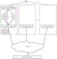
如图1和图2所示,一种监管系统,包括设于监控中心的粮仓管理信息系统,以及设于每个粮仓的信息收发控制终端,粮仓温湿监测单元,激发/充电源模块和相应的降温、除湿和通风设备;每个粮仓的信息收发控制终端通过通信网络与粮仓管理信息系统相连接,信息收发控制终端通过控制信号与降温、除湿和通风设备相连接,粮仓温湿监测单元通过高频无线方式与同舱的信息收发控制终端相连接,激发/充电源模块通过无线或有线的方式与同舱的信息收发控制终端相连接,激发/充电源模块通过低频无线方式与同舱的粮仓温湿监测单元相连接;所述的激发/充电源模块含有受信息收发控制终端控制发送的激发信号程序模块和充电信号程序模块;所述的信息收发控制终端含有翻仓质量评价程序模块和根据偷盗量分级报警程序模块。As shown in Figures 1 and 2, a supervision system includes a granary management information system located in the monitoring center, an information sending and receiving control terminal located in each granary, a granary temperature and humidity monitoring unit, an excitation/charging source module and corresponding Cooling, dehumidification and ventilation equipment; the information sending and receiving control terminal of each granary is connected with the granary management information system through the communication network, the information sending and receiving control terminal is connected with the cooling, dehumidification and ventilation equipment through the control signal, and the temperature and humidity monitoring unit of the granary is connected by The high-frequency wireless method is connected to the information transceiver control terminal in the same cabin, the excitation/charging source module is connected to the information transceiver control terminal in the same cabin by wireless or wired, and the excitation/charging source module is connected to the same cabin through the low-frequency wireless method. The temperature and humidity monitoring unit of the granary is connected; the excitation/charging source module includes an excitation signal program module and a charging signal program module sent under the control of the information transceiver control terminal; the information transceiver control terminal includes a warehouse turnover quality evaluation program module and The alarm program module is graded according to the amount of theft.
所述粮仓温湿监测单元包括:整流模块100、解调解码控制模块200、电池充电模块300、温湿采集模块400、温感开关500、压力开关模块700、低频天线600、电池E、第一场效应管Q1、第二场效应管Q2、第三场效应管Q3、第四场效应管Q4、第五场效应管Q5、第六场效应管Q6、第七场效应管Q7;低频天线600通过无线方式与粮仓内的激发/充电源模块相连接,接收激发/充电源模块发送的激发/充电源信号;低频天线600分别与整流模块100和解调解码控制模块200的输入相连接;整流模块100的输出分别与解调解码控制模块200的电源输入和第三场效应管Q3的源极相连接,第三场效应管Q3的漏极与电池充电模块300的输入相连接,第三场效应管Q3的柵极与第二场效应管Q2的漏极相连接,第二场效应管Q2的柵极与解调解码控制模块200的一输出相连接,第二场效应管Q2的源极与电池E的负极相连接;电池充电模块300的充电输出与压力开关模块700的输入相并接后接入电池E的正极;电池充电模块300的一信号输出与温湿采集模块400的输入相连接,电池充电模块300的另一信号输出与解调解码控制模块200的输入相连接;第一场效应管Q1的柵极与解调解码控制模块200的另一输出相连接,第一场效应管Q1的源极与电池E的负极相连接;压力开关模块700的输出与第五场效应管Q5的柵极相连接;第五场效应管Q5的源极与电池E的负极相连接;第四场效应管Q4的栅极与温湿采集模块400的输出相连接,第四场效应管Q4的的源极与电池E的负极相连接;第六场效应管Q6的源极、第七场效应管Q7的源极及温感开关500的一端相互并接后与电池E的正极相连接,第六场效应管Q6的漏极、第七场效应管Q7的漏极及温感开关500的另一端相互并接后接入温湿采集模块400的电源输入,第六场效应管Q6的柵极与第一场效应管Q1的漏极和第四场效应管Q4的漏极相互并接;第五场效应管Q5的漏极与第七场效应管Q7的柵极相连接,并从其连接线上引线至温湿采集模块400的中断输入和数字输入;温湿采集模块400通过无线方式与信息收发控制终端相连接;整流模块100的电源负极、电池充电模块300的电源负极、温湿采集模块400的电源负极及压力开关模块700的电源负极与电池E的负极相连接。The granary temperature and humidity monitoring unit includes: a
以上所述的第一场效应管Q1、第二场效应管Q2、第四场效应管Q4及第五场效应管Q5均为N沟道增强型MOS管;以上所述的第三场效应管Q3、第六场效应管Q6及第七场效应管Q7均为P沟道增强型MOS管。The above-mentioned first field effect transistor Q1, second field effect transistor Q2, fourth field effect transistor Q4 and fifth field effect transistor Q5 are all N-channel enhancement type MOS transistors; the above-mentioned third field effect transistor Q3, the sixth field effect transistor Q6 and the seventh field effect transistor Q7 are all P-channel enhancement type MOS transistors.
以上所述的压力开关模块700包括:电阻R1,电阻R2,受力按钮AN,电容C;电容C的正极与电阻R1的一端相并接后接入电池E的正极,电阻R1的另一端串接受力按钮AN的常开触点后与电容C的负极相连接;电容C的负极串接受力按钮AN的常闭触点后与电阻R2的一端相连接,电阻R2的另一端与电池E的负极相连接;从受力按钮AN的常闭触点与电阻R2的连接线上引线接入第五场效应管Q5的柵极。The
以上所述的受力按钮AN为双路触点开关,一路为常开,另一路为常闭,并设置受力按钮AN受力面受力为:受力大于等于5千克力时,常开的一路触点闭合,常闭的一路触点断开;受力小于5千克力时,常开的一路触点断开(保持常开),常闭的一路触点闭合(保持常闭)。即当受力按钮AN的受力面受力大于等于5千克力时,常开的一路触点闭合,常闭的一路触点断开,当受力按钮AN的受力面受力小于5千克力时,常开的一路触点恢复为断开,常闭的一路触点恢复为接通(闭合)。本发明监管系统中粮仓温湿监测单元安装于承载盒内,且受力按钮AN的受力面成凹型设于粮仓温湿监测单元承载盒的面板上,即受力按钮AN的受力面凹入承载盒的面板,有利于在粮仓温湿监测单元运输、备用存放过程中不易受外部压力影响触发电池E供电电路通电,从而提高电池E使用寿命。The above-mentioned force button AN is a two-way contact switch, one is normally open and the other is normally closed, and the force on the force surface of the force button AN is set as follows: when the force is greater than or equal to 5 kgf, the normally open The one-way contact of the normally closed is closed, and the normally-closed one-way contact is disconnected; when the force is less than 5 kgf, the normally-open one-way contact is disconnected (keep normally open), and the normally-closed one-way contact is closed (keep normally closed). That is, when the force of the force-bearing surface of the force-bearing button AN is greater than or equal to 5 kg force, the normally open one-way contact is closed, and the normally-closed one-way contact is disconnected, when the force of the force-bearing surface of the force-bearing button AN is less than 5 kg. When the force is applied, the normally open one-way contact returns to open, and the normally closed one-way contact returns to on (closed). In the monitoring system of the present invention, the granary temperature and humidity monitoring unit is installed in the bearing box, and the force-bearing surface of the force-bearing button AN is concavely arranged on the panel of the granary temperature and humidity monitoring unit bearing box, that is, the force-bearing surface of the force-bearing button AN is concave. It is beneficial to not be affected by external pressure during the transportation and backup storage of the temperature and humidity monitoring unit of the granary and trigger the power supply circuit of the battery E to energize, thereby improving the service life of the battery E.
以上所述的电容C选择漏电少的电容,如钽电容、铌电容等。For the capacitor C mentioned above, select capacitors with less leakage, such as tantalum capacitors, niobium capacitors, and the like.
压力开关模块700中,电池E经电容C、受力按钮AN的常闭触点及电阻R2形成的充电回路,其充电回路的断开与接通由受力按钮AN的常闭触点控制。受力按钮AN的常闭触点断开,电容C与电阻R2串接形成的充电回路断开,受力按钮AN的常开触点接通,电容C通过电阻R1放电。保证安全的情况下,电阻R1尽量小,以确保受力按钮AN的受力面受力大于等于5千克力时,即受力按钮AN的常开触点接通后,电容C以较短的时间放完电。以电阻R2与受力按钮AN的常闭触点端的连接线电压为输出信号,即以电阻R2上降压为压力开关模块70的输出信号,引至第五场效应管Q5的栅极。电池E经电容C、受力按钮AN的常闭触点及电阻R2形成充电回路的充电过程中,降在电阻R2上的电压,随着电容C的充电,从等于电池E电压逐渐减小,待电容C充满或受力按钮AN的常闭触点断开时,电阻R2上的降压为零。对电容C和电阻R2大小选择的要求是:充电过程中,从电阻R2上取得的大于等于第五场效应管Q5开启电压UGS(th)的控制电压,得保持到温湿采集模块400通电控制第四场效应管Q4从截止进入导通状态之后。In the
第五场效应管Q5的导通与截止受压力开关模块700输出控制,压力开关模块700输出大于等于第五场效应管Q5开启电压UGS(th),第五场效应管Q5导通,否则第五场效应管Q5截止;第七场效应管Q7的导通与截止受第五场效应管Q5输出控制,第五场效应管Q5导通,第七场效应管Q7导通;第五场效应管Q5截止,第七场效应管Q7截止。The turn-on and turn-off of the fifth field effect transistor Q5 is controlled by the output of the
第六场效应管Q6、第七场效应管Q7及温感开关500的开关以并联方式:控制电池E到温湿采集模块400的电源输入通路。The switches of the sixth field effect transistor Q6, the seventh field effect transistor Q7 and the
以上所述的激发/充电源模块用于对粮仓温湿监测单元产生激发和充电的信号,其含有受信息收发控制终端控制发送的激发信号程序模块和充电信号程序模块。激发/充电源模块通过无线方式与粮仓温湿监测单元中低频天线600相连接。激发/充电源模块并与信息收发控制终端相连接,激发/充电源模块所发信号受信息收发控制终端控制。当信息收发控制终端输出巡检控制信息至激发/充电源模块,激发/充电源模块接收到巡检控制信息,执行激发信号程序模块,发出激发信号,所发出的激发信号中含有激发编码,且设置同一个粮仓内粮仓温湿监测单元中激发编码一致;当信息收发控制终端输出停止巡检控制信息至激发/充电源模块,激发/充电源模块接收到停止巡检控制信息,停止执行激发信号程序模块,激发/充电源模块终止激发信号发出。当信息收发控制终端输出充电控制信息至激发/充电源模块,激发/充电源模块接收到充电控制信息,执行充电信号程序模块,发出充电信号,所发出的充电信号中含有充电编码,同样设置同一个粮仓内粮仓温湿监测单元中充电编码一致;当信息收发控制终端输出停止充电控制信息至激发/充电源模块,激发/充电源模块接收到停止充电控制信息,停止执行充电信号程序模块,激发/充电源模块终止充电信号发出。The above-mentioned excitation/charging source module is used to generate excitation and charging signals for the temperature and humidity monitoring unit of the granary, and includes an excitation signal program module and a charging signal program module that are controlled and sent by the information transceiver control terminal. The excitation/charging source module is wirelessly connected to the low-
所述信息收发控制终端为中间节点,用于具体对粮仓内粮仓温湿监测单元巡检和实时接收,以及对激发/充电源模块输出信号控制,信息收发控制终端通过高频无线方式与粮仓温湿监测单元中温湿采集模块400相连接,信息收发控制终端通过网络与监控中心的粮仓管理信息系统相连接,并通过有线或无线与激发/充电源模块相连接,根据要求输出相应的控制信号至激发/充电源模块;且信息收发控制终端还连接有至调温、排湿、通风设备的控制信号,以及与红外、摄像防盗末端装置相连接。The information sending and receiving control terminal is an intermediate node, which is used for specific inspection and real-time reception of the temperature and humidity monitoring unit of the granary in the granary, and control of the output signal of the excitation/charging source module. The temperature and
当信息收发控制终端要求对粮仓温湿监测单元巡检,输出巡检控制信息至激发/充电源模块,信息收发控制终端待到与所在粮仓内3个以上粮仓温湿监测单元建立通信连接,则输出停止巡检控制信息至激发/充电源模块,并传递巡检信息标记至粮堆中所有的粮仓温湿监测单元。When the information sending and receiving control terminal requests to inspect the temperature and humidity monitoring unit of the granary, and outputs the inspection control information to the excitation/charging source module, the information sending and receiving control terminal waits until the communication connection is established with more than three granary temperature and humidity monitoring units in the granary. Output the stop inspection control information to the excitation/charging source module, and transmit the inspection information mark to all granary temperature and humidity monitoring units in the grain pile.
当信息收发控制终端要求对粮仓温湿监测单元中电池E补充电量,输出充电控制信息至激发/充电源模块,信息收发控制终端待接收到所在粮仓内所有的粮仓温湿监测单元发出电池充满信号,输出停止充电控制信息至激发/充电源模块。When the information transceiver control terminal requests to replenish the battery E in the granary temperature and humidity monitoring unit, and outputs the charging control information to the excitation/charging source module, the information transceiver control terminal will receive a battery full signal from all the granary temperature and humidity monitoring units in the granary where it is located. , and output stop charging control information to the excitation/charging source module.
当充电过程中需巡检,信息收发控制终端立即输出停止充电控制信息至激发/充电源模块,跟着输出巡检控制信息至激发/充电源模块。When inspection is required during the charging process, the information transceiver control terminal immediately outputs stop charging control information to the excitation/charging source module, and then outputs the inspection control information to the excitation/charging source module.
所述的低频天线600对激发/充电源模块所发信号接收,送整流模块100的电源输入端和解调解码控制模块200的信号输入端,所述整流模块100对低频天线600所接信号整流稳压输出工作电压至解调解码控制模块200的电源输入端和第三场效应管Q3的源端。The low-
所述解调解码控制模块200对低频天线600所接信号解调和解码,解调解码控制模块200并存有激发编码和充电编码,解调解码控制模块200将所解的编码与所存储的激发编码和充电编码比较:为激发编码时,输出高电位(大于等于第一场效应管Q1的开启电压UGS(th))至第一场效应管Q1的柵极,输出低电位(小于第二场效应管Q2的开启电压UGS(th))至第二场效应管Q2的柵极,第一场效应管Q1导通,第二场效应管Q2截止;为充电编码时,输出低电位(小于第一场效应管Q1的开启电压UGS(th))至第一场效应管Q1的柵极,输出高电位(大于等于第二场效应管Q2的开启电压UGS(th))至第二场效应管Q2的柵极,第一场效应管Q1截止,第二场效应管Q2导通。解调解码控制模块200未接收其激发编码和充电编码信号,输出低电位至第一场效应管Q1和第二场效应管Q2的柵极,第一场效应管Q1和第二场效应管Q2均截止。The demodulation and
解调解码控制模块200在通过第二场效应管Q2控制第三场效应管Q3导通,整流模块100的输岀经第三场效应管Q3送电池充电模块300对电池E充电期间,解调解码控制模块200响应电池充电模块300输入的电池是否充满信号,解调解码控制模块200待接收到电池充电模块300输入的电池充满信号,解调解码控制模块200输出高电位至第一场效应管Q1的柵极,输出低电位至第二场效应管Q2的柵极,第一场效应管Q1导通,第二场效应管Q2截止,解调解码控制模块200暂停相应充电信号,延时3秒输出低电位至第一场效应管Q1的柵极,使第一场效应管Q1进入截止,或不延时,待解调解码控制模块200无工作电源结束,即电池E充满后,解调解码控制模块200接收到充电信号,仍然保持输出低电位至第二场效应管Q2的柵极,并保持输出至第一场效应管Q1的柵极的控制电压不变。During the period when the demodulation
待解调解码控制模块200无供电,输出至第一场效应管Q1和第二场效应管Q2栅极的电压为零,第一场效应管Q1和第二场效应管Q2截止,暂停功能自动消失。The
解调解码控制模块200暂停相应充电信号期间,解调解码控制模块200不失工作电源,情况下,待接收到激发编码后,解除暂停充电功能,即待接收到激发编码后,解调解码控制模块200下次又相应充电信号。During the period when the demodulation and
第二场效应管Q2截止,第三场效应管Q3截止;第二场效应管Q2导通,第三场效应管Q3导通。The second field effect transistor Q2 is turned off, and the third field effect transistor Q3 is turned off; the second field effect transistor Q2 is turned on, and the third field effect transistor Q3 is turned on.
第三场效应管Q3截止,整流模块100的输出不能经第三场效应管Q3通过电池充电模块300对电池E充电,即第三场效应管Q3截止,整流模块100输出的电压停止经第三场效应管Q3通过电池充电模块300对电池E充电。第三场效应管Q3导通,整流模块100输出的电压经第三场效应管Q3通过电池充电模块300对电池E充电。The third field effect transistor Q3 is turned off, and the output of the
电池充电模块300包含有对电池E充电电路和电池E是否充满监测电路。电池充电模块300的充电输出与电池E的正极相连接,电池E是否充满监测电路的输出与解调解码控制模块200的输入和温湿采集模块400的输入相连接。The
当第一场效应管Q1和第四场效应管Q4中任一场效应管导通时,加至第六场效应管Q6柵源间控制电压UGS小于等于其开启电压UGS(th),第六场效应管Q6导通。When any one of the first field effect transistor Q1 and the fourth field effect transistor Q4 is turned on, the gate-source control voltage UGS applied to the sixth field effect transistor Q6 is less than or equal to its turn-on voltage UGS(th), the sixth field effect transistor Q6 The field effect transistor Q6 is turned on.
当第一场效应管Q1和第四场效应管Q4均截止时,加至第六场效应管Q6柵源间控制电压UGS大于其开启电压UGS(th),第六场效应管Q6截止。When both the first field effect transistor Q1 and the fourth field effect transistor Q4 are turned off, the gate-source control voltage UGS applied to the sixth field effect transistor Q6 is greater than its turn-on voltage UGS(th), and the sixth field effect transistor Q6 is turned off.
所述温感开关500用于超温时开启电池E供电,实现超温实时报警。The temperature-
所述温感开关500为无源物理触点开关,其触点为常开型,即:设置温感开关500感应到温度小于其设定温度时,温感开关500的触点处于断开,正常工作状态;温感开关500感应到温度大于等于其设定温度时,温感开关500的触点接通(闭合),闭合后的温感开关500待感应到温度小于其设定温度,温感开关500的触点恢复为正常工作状态,即断开。The temperature-
一般粮仓粮堆内温度常年要求保持在30℃以下,则本发明采用温感开关500的设定温度为:30℃加上5℃,即当温感开关500感应到温度大于等于35℃时,电池E经温感开关500接入温湿采集模块400,温湿采集模块400通电工作。Generally, the temperature in the grain pile of the granary is required to be kept below 30°C all the year round, so the present invention adopts the set temperature of the
所述温湿采集模块400,用于具体的温湿、防盗、翻仓、放粮、电池E电量等釆集读取并上至信息收发控制终端进行相应控制,其包括温湿检测处理控制单元410、无线收发单元420、温度传感器430、湿度传感器440、高频天线450、指示灯460;所述温湿检测处理控制单元410依次串接无线收发单元420、高频天线450后以无线方式与信息收发控制终端建立连接;温湿检测处理控制单元410输入接有温度传感器430、湿度传感器440、第五场效应管Q5漏极及电池充电模块300;温湿检测处理控制单元410输出接有第四场效应管Q4的栅极和指示灯460;所述的第五场效应管Q5漏极与温湿检测处理控制单元410的中断输入和数字输入相连接,并设定温湿检测处理控制单元410低电平响应第五场效应管Q5输出中断申请。所述的温湿检测处理控制单元410是进行信息处理控制单元,对相应的输入信号进行采集处理和上传,并根据处理结果通过输出相应控制,温湿检测处理控制单元410包括:中央处理器、与输入/输出电路相适应的输入/输出接口、EEPROM存储器,并设有相应的ID编码,以及嵌入相应的检测识别控制程序模块和与信息收发控制终端通信的程序模块,还嵌入低电平响应第五场效应管Q5输出的中断服务程序模块;还含有电池E的电压监测电路。The temperature and
当压力开关模块700的输出大于零电压时,说明受力按钮AN的常闭触点处于接通,即说明受力按钮AN的受力面受力小于5千克力,且常闭触点处于接通时间的小于电容C充满所需要的时间,也可以说常闭触点接通维持的时间小于电容C充满所需要的时间。当压力开关模块700的输出的电压越接近电池E的端电压,说明常闭触点接通是刚刚发生,压力开关模块700输出的电压值越小,说明常闭触点接通并维持到当前的时间越长。当压力开关模块700的输出等于零电压时,说明受力按钮AN的常闭触点处于断开或常闭触点接通并维持到当前的时间大于电容C充满所需要的时间,即当压力开关模块700的输出等于零电压时,说明受力按钮AN的受力面受力大于等于5千克力或说明常闭触点接通并维持到当前的时间已久远。When the output of the
由于设于粮堆中的粮仓温湿监测单元,平时是处静状态,且处于静态状的时间远远大于其电容C的充满需要的时间,故粮堆中粮仓温湿监测单元平时是处静状态的,不管其受力按钮AN的受力面受力大小如何,压力开关模块700的输出均等于零电压时。Since the temperature and humidity monitoring unit of the granary in the grain pile is usually in a static state, and the time in the static state is much longer than the time required for the capacitor C to be fully charged, the temperature and humidity monitoring unit of the granary in the grain pile is usually in a static state. No matter what the force is on the force-bearing surface of the force-bearing button AN, the output of the
故本发明向粮堆中设入粮仓温湿监测单元时,上层得保证其受力按钮AN的受力面受力大于等于5千克力。Therefore, when the granary temperature and humidity monitoring unit is installed in the grain pile in the present invention, the upper layer must ensure that the force of the force-bearing surface of the force-bearing button AN is greater than or equal to 5 kgf.
由于翻仓和放粮及防盗应是实时捕捉当前的行为,故本发明中断服务程序模块响应第五场效应管Q5输出的过程中,设置为低电平响应中断,当中断响应第五场效应管Q5输出,则认定当前正在翻仓或放粮或粮食被盗;不响应第五场效应管Q5输出,认定当前既不在翻仓和放粮,粮食也没有被盗。Since warehouse turnover, grain release and anti-theft should be real-time capture of the current behavior, the interrupt service program module of the present invention is set to a low level in the process of responding to the output of the fifth field effect transistor Q5, and when the interrupt responds to the fifth field effect If the output of Q5 is controlled, it is determined that the warehouse is currently being turned over or grain is put in or the grain has been stolen; if it does not respond to the output of Q5 of the fifth FET, it is determined that the warehouse is not being turned over or grain is currently being released, and the grain has not been stolen.
温湿采集模块400中温湿检测处理控制单元410通电处始化后,立即输岀高电平至第四场效应管Q4的栅极,第四场效应管Q4导通,从而使第六场效应管Q6导通/保持导通;待到第五场效应管Q5输出发出中断申请,认定压力开关模块700有输出信息,说明当前正在翻仓或放粮或粮食被盗,屏蔽第五场效应管Q5输出的中断申请,并接管对第四场效应管Q4关断控制,上传压力开关模块700有输出信息至信息收发控制终端,否则,认定当前既没有翻仓和放粮,粮食也没有被盗。After the temperature and humidity detection
响应第五场效应管Q5输出发出中断申请的同时,屏蔽温湿检测及电池充满识别,直到温湿采集模块400失电。When the interrupt request is issued in response to the output of the fifth FET Q5, the temperature and humidity detection and the battery full identification are shielded until the temperature and
指示灯460用于翻仓和放粮期间,识别到正在此位置翻仓或放粮,闪烁点亮,从而方便翻仓和放粮过程中找到对应的粮仓温湿监测单元。The
所述的信息收发控制终端嵌入有翻仓质量评价程序模块和根据偷盗量分级报警程序模块。当时间段设置为翻仓,执行翻仓质量评价程序模块,当时间段设置为防盗,执行根据偷盗量分级报警程序模块。The information sending and receiving control terminal is embedded with a quality evaluation program module for warehouse turnover and a grading alarm program module according to the amount of theft. When the time period is set as warehouse turnover, the quality evaluation program module for warehouse turnover is executed, and when the time period is set as anti-theft, the grading alarm program module according to the amount of theft is executed.
当温湿检测处理控制单元410向信息收发控制终端上传压力开关模块700有输出信息后,温湿检测处理控制单元410等待信息收发控制终端对有输出信息的响应信息,当该时间段设定为翻仓或放粮,不管是翻仓或放粮,统一反馈翻仓/放粮标识码至相应的粮仓温湿监测单元中温湿检测处理控制单元410,若且为翻仓时间段,进行翻仓质量判断;当该时间段设定为防盗,反馈防盗标识码至相应的粮仓温湿监测单元中温湿检测处理控制单元410,且进行有偷盗报警提示;若为放粮时间段,不做任何评价。After the temperature and humidity detection
温湿检测处理控制单元410识别到反馈的为翻仓/放粮标识码,温湿检测处理控制单元410点亮指示灯460。温湿检测处理控制单元410点亮指示灯460后,温湿检测处理控制单元410通过数字输入口读取第五场效应管Q5的输出,设定待连续3次检测识别到第五场效应管Q5的输出从高电平到低电平,且连续3次的时间小于10秒,则温湿检测处理控制单元410熄灭点亮的指示灯460,否则,保持指示灯点亮460;熄灭点亮的指示灯460后,输出低电平至第四场效应管Q4的栅极,并进入休眠状态,直至温湿采集模块400失电。The temperature and humidity detection and
温湿检测处理控制单元410识别到反馈的为防盗标识码,输出低电平至第四场效应管Q4的栅极,并进入休眠状态,直至温湿采集模块400失电。The temperature and humidity detection
当信息收发控制终端在其设置的翻仓时间段,则进行翻仓质量判断:对该时间段内粮堆中上传过有输出信息的粮仓温湿监测单元进行累计,并计算其占粮堆中所设置的粮仓温湿监测单元总量的比率,且将该比率设定为:有输出信息的总占比率,并设定采用有输出信息的总占比率来作为翻仓质量的评定指标,有输出信息的总占比率越高,认定翻仓质量越好,反之相反。本发明设定:有输出信息的总占比率达到大于等于95%时,认定翻仓质量为优秀;有输出信息的总占比率达到大于等于85%,小于95%,认定翻仓质量为合格;有输出信息的总占比率达不到85%,认定翻仓质量为不合格。When the information sending and receiving control terminal is in the silo-turning time period set by it, it will judge the silo-turning quality: accumulate the temperature and humidity monitoring units of the granary that have output information uploaded in the grain pile during this time period, and calculate the proportion of the granary in the grain pile. The ratio of the total amount of temperature and humidity monitoring units in the granary is set, and the ratio is set as: the total proportion of output information, and the total proportion of output information is set as the evaluation index for the quality of warehouse turnover. The higher the total proportion of output information, the better the quality of the turnover is determined, and vice versa. The present invention sets that: when the total proportion of output information is greater than or equal to 95%, the quality of warehouse turnover is determined to be excellent; the total proportion of output information is greater than or equal to 85%, and less than 95%, and the quality of warehouse turnover is determined to be qualified; If the total proportion of output information is less than 85%, it is determined that the quality of the warehouse turnover is unqualified.
当信息收发控制终端在其设置的防盗时间段,则进行报警分级判断:设定规定时间长度,对规定时间长度内上传过有输出信息的粮仓温湿监测单元进行累计,并计算其占粮堆中所设置的粮仓温湿监测单元总量的比率,且将该比率设定为:有输出信息的分占比率,并设定采用有输出信息的分占比率来作为报警分级的评定指标,短时间内有输出信息的分占比率越高,认定该时间内偷盗严重,增加报警的次数和逐层向上报警的顶层级别越高,反之相反。举例:如假设:最低级别为具体工作人员,中间级别为具体管理层,最高级别为地方政府和本地区公民;本发明设置规定时间长度为4小时,设定:有输出信息的分占比率达不到1%(且大于0),只向最低级别的具体工作人员报警,且每天2次,直到防盗解除;有输出信息的分占比率达到大于等于1%,小于5%,则向最低级别具体工作人员报警的同时,且向中间级别的具体管理层报警,报警的次数增到每天4次,直到防盗解除;有输出信息的分占比率达到大于等于5%,除向最低级别具体工作人员及中间级别具体管理层外,还向最高级别的地方政府和本地区公民报警,报警的次数增到每天6次,直到防盗解除。报警可通过手机、电视、网络等终端呈现。When the information sending and receiving control terminal is in the anti-theft time period set by it, it will make an alarm classification judgment: set a specified time length, accumulate the temperature and humidity monitoring units of the granary that have output information uploaded within the specified time length, and calculate the proportion of the grain pile. The ratio of the total amount of temperature and humidity monitoring units in the granary set in , and the ratio is set as: the proportion of output information, and the proportion of output information is set as the evaluation index of alarm classification, short The higher the percentage of output information within the time period, the higher the number of alarms and the higher the top-level level of alarming, and vice versa. For example: Assume: the lowest level is specific staff, the middle level is specific management, and the highest level is local government and local citizens; the present invention sets the specified time length to 4 hours, and sets: the proportion of output information is up to Less than 1% (and greater than 0), only alarm the specific staff at the lowest level, and twice a day until the anti-theft is lifted; if the proportion of output information is greater than or equal to 1%, and less than 5%, the lowest level will be reported. At the same time when the specific staff alarms, they also alarm the specific management at the intermediate level. The number of alarms increases to 4 times a day until the anti-theft is lifted; the proportion of output information reaches 5% or more, except for the specific staff at the lowest level. In addition to the specific management at the intermediate level, the local government at the highest level and the citizens of the region were also reported to the police, and the number of alarms was increased to 6 times a day until the anti-theft was lifted. Alarms can be presented through terminals such as mobile phones, TVs, and the Internet.
粮仓温湿监测单元中温湿采集模块400通电控制第四场效应管Q4导通后,待响应第五场效应管Q5输出的中断申请,则接管对第四场效应管Q4关断的控制,其控制由信息收发控制终端返回的翻仓/放粮标识码和防盗标识码决定,否则,由原功能决定。原功能的决定是:待完成温度、湿度及电池E充满标记检测识别并上传任务后,输出低电平至第四场效应管Q4的栅极;输出低电平至第四场效应管Q4的栅极后,若温湿采集模块400不失电,则继续进行温度和湿度检测并上传,直至温湿采集模块400失电。After the temperature and
信息收发控制终端根据接收的温湿信息进行处理并根据结果进行相应的降温和排湿控制。The information transceiver control terminal processes according to the received temperature and humidity information and performs corresponding cooling and dehumidification control according to the results.
将粮仓温湿监测单元布入粮堆过程是:在粮堆集过程中从底往上以垂直1.5米层厚放入粮仓温湿监测单元,且在每层上以小于5米的间距放置,并将具体放入设定层面的粮仓温湿监测单元相应ID编号录入粮仓管理系统。The process of placing the granary temperature and humidity monitoring unit into the grain pile is as follows: during the grain accumulation process, the granary temperature and humidity monitoring unit is placed in a vertical layer thickness of 1.5 meters from the bottom to the top, and is placed on each layer at a distance of less than 5 meters, and Enter the corresponding ID number of the temperature and humidity monitoring unit of the granary into the granary management system.
Claims (6)
Translated fromChinesePriority Applications (1)
| Application Number | Priority Date | Filing Date | Title |
|---|---|---|---|
| CN201811501197.1ACN109658661B (en) | 2018-12-10 | 2018-12-10 | A kind of supervision system and its realization method |
Applications Claiming Priority (1)
| Application Number | Priority Date | Filing Date | Title |
|---|---|---|---|
| CN201811501197.1ACN109658661B (en) | 2018-12-10 | 2018-12-10 | A kind of supervision system and its realization method |
Publications (2)
| Publication Number | Publication Date |
|---|---|
| CN109658661A CN109658661A (en) | 2019-04-19 |
| CN109658661Btrue CN109658661B (en) | 2020-10-16 |
Family
ID=66113498
Family Applications (1)
| Application Number | Title | Priority Date | Filing Date |
|---|---|---|---|
| CN201811501197.1AActiveCN109658661B (en) | 2018-12-10 | 2018-12-10 | A kind of supervision system and its realization method |
Country Status (1)
| Country | Link |
|---|---|
| CN (1) | CN109658661B (en) |
Citations (15)
| Publication number | Priority date | Publication date | Assignee | Title |
|---|---|---|---|---|
| EP0865161A2 (en)* | 1997-03-13 | 1998-09-16 | Denso Corporation | Driving apparatus for an inductive load |
| KR20020048335A (en)* | 2002-04-24 | 2002-06-22 | 최삼봉 | Device for alarming the invasion of theft using a pair of tranceiver |
| JP2005506747A (en)* | 2001-10-15 | 2005-03-03 | スリーエム イノベイティブ プロパティズ カンパニー | Amplifier modulation |
| CN101577031A (en)* | 2008-05-07 | 2009-11-11 | 群康科技(深圳)有限公司 | Alarm system |
| CN102013737A (en)* | 2010-10-12 | 2011-04-13 | 浙江大学 | Wirelessly charged sensor node |
| CN102881118A (en)* | 2010-09-03 | 2013-01-16 | 中国石油化工股份有限公司 | Portable toxic gas monitoring device and method |
| CN104662768A (en)* | 2013-09-04 | 2015-05-27 | 日东电工株式会社 | Portable device, charging system, power supply circuit board, etc. |
| CN204759504U (en)* | 2015-08-02 | 2015-11-11 | 朱江 | Warehouse goods and materials safety monitoring system |
| CN106197696A (en)* | 2016-07-26 | 2016-12-07 | 浙江理工大学 | A wireless recording device and recording method for fabric temperature of a sizing machine |
| CN106921194A (en)* | 2017-03-17 | 2017-07-04 | 中国农业大学 | Collector wireless charging method, collector, control terminal and system |
| CN206431117U (en)* | 2017-01-17 | 2017-08-22 | 宝鸡文理学院 | A kind of grain environment monitoring device |
| CN206851425U (en)* | 2017-06-08 | 2018-01-09 | 马建海 | From turning over ventilation silo |
| CN107991934A (en)* | 2017-12-21 | 2018-05-04 | 安徽华宇机械制造有限公司 | A kind of silo safety monitoring system |
| CN108280611A (en)* | 2018-02-05 | 2018-07-13 | 金东纸业(江苏)股份有限公司 | A kind of intelligent warehouse management system |
| CN108665660A (en)* | 2018-07-09 | 2018-10-16 | 邬金龙 | A kind of grain burglary-resisting system and its working method |
- 2018
- 2018-12-10CNCN201811501197.1Apatent/CN109658661B/enactiveActive
Patent Citations (15)
| Publication number | Priority date | Publication date | Assignee | Title |
|---|---|---|---|---|
| EP0865161A2 (en)* | 1997-03-13 | 1998-09-16 | Denso Corporation | Driving apparatus for an inductive load |
| JP2005506747A (en)* | 2001-10-15 | 2005-03-03 | スリーエム イノベイティブ プロパティズ カンパニー | Amplifier modulation |
| KR20020048335A (en)* | 2002-04-24 | 2002-06-22 | 최삼봉 | Device for alarming the invasion of theft using a pair of tranceiver |
| CN101577031A (en)* | 2008-05-07 | 2009-11-11 | 群康科技(深圳)有限公司 | Alarm system |
| CN102881118A (en)* | 2010-09-03 | 2013-01-16 | 中国石油化工股份有限公司 | Portable toxic gas monitoring device and method |
| CN102013737A (en)* | 2010-10-12 | 2011-04-13 | 浙江大学 | Wirelessly charged sensor node |
| CN104662768A (en)* | 2013-09-04 | 2015-05-27 | 日东电工株式会社 | Portable device, charging system, power supply circuit board, etc. |
| CN204759504U (en)* | 2015-08-02 | 2015-11-11 | 朱江 | Warehouse goods and materials safety monitoring system |
| CN106197696A (en)* | 2016-07-26 | 2016-12-07 | 浙江理工大学 | A wireless recording device and recording method for fabric temperature of a sizing machine |
| CN206431117U (en)* | 2017-01-17 | 2017-08-22 | 宝鸡文理学院 | A kind of grain environment monitoring device |
| CN106921194A (en)* | 2017-03-17 | 2017-07-04 | 中国农业大学 | Collector wireless charging method, collector, control terminal and system |
| CN206851425U (en)* | 2017-06-08 | 2018-01-09 | 马建海 | From turning over ventilation silo |
| CN107991934A (en)* | 2017-12-21 | 2018-05-04 | 安徽华宇机械制造有限公司 | A kind of silo safety monitoring system |
| CN108280611A (en)* | 2018-02-05 | 2018-07-13 | 金东纸业(江苏)股份有限公司 | A kind of intelligent warehouse management system |
| CN108665660A (en)* | 2018-07-09 | 2018-10-16 | 邬金龙 | A kind of grain burglary-resisting system and its working method |
Non-Patent Citations (4)
| Title |
|---|
| "Real-time remote monitoring and automated control of granary environmental factors using wireless sensor network";M.O.Onibonoje;《IEEE International Conference on Power, Control, Signals and Instrumentation Engineering》;20171231;113-118页* |
| "Manjunath lakkannavar. The Design of Granary Environmental Monitoring and Control System Based On ARM9 and ZIGBEE";Hemanth Kumar G;《international journal of innovative technology & exploring engineering》;20121231;第1卷(第3期);全文* |
| "基于FIX的粮库自动化控制系统的研究与应用";李燕林;《中国优秀硕士学位论文全文数据库 信息科技辑》;20071215(第06(2007年)期);全文* |
| "粮食仓库分布式微机自动控制系统";曹林根等;《电工技术杂志》;19851231(第10(1985年)期);23-27页* |
Also Published As
| Publication number | Publication date |
|---|---|
| CN109658661A (en) | 2019-04-19 |
Similar Documents
| Publication | Publication Date | Title |
|---|---|---|
| CN109658661B (en) | A kind of supervision system and its realization method | |
| CN208751626U (en) | A kind of self-charging type grain temperature-humidity monitoring early warning system based on wireless transmission | |
| CN108200662A (en) | Urban track traffic civil engineering facility intelligent monitor system | |
| CN216774834U (en) | Automatic on-line monitoring device for recognizing switch state | |
| CN109523725B (en) | A monitoring unit guided by an indicator light and its realization method | |
| CN109448309B (en) | A supervisory unit with indicator light and its realization method | |
| CN109556742B (en) | A kind of temperature and humidity unit with anti-theft and its realization method | |
| CN109596172B (en) | A granary temperature and humidity monitoring unit and its realization method | |
| CN109600435B (en) | Monitoring unit with turning prompt and implementation method thereof | |
| CN109696935B (en) | A management system with quality evaluation of warehouse turnover and its realization method | |
| CN204480457U (en) | A kind of Internet of Things warning system | |
| CN109462658B (en) | Granary monitoring and management system and implementation method thereof | |
| CN109739287B (en) | Monitoring unit and implementation method thereof | |
| CN109710005B (en) | A monitoring system and its realization method | |
| CN109741571B (en) | Temperature and humidity monitoring unit with antitheft function and implementation method thereof | |
| CN109765873B (en) | Monitoring unit capable of acquiring theft behavior and implementation method thereof | |
| CN109816930B (en) | A temperature and humidity monitoring unit and its realization method | |
| CN205281722U (en) | Intelligence household security service robot | |
| CN109596171B (en) | Temperature and humidity monitoring unit and implementation method thereof | |
| CN109579912B (en) | Monitoring unit and implementation method thereof | |
| CN109709883B (en) | A monitoring unit with anti-theft and its realization method | |
| CN205302528U (en) | Infrared detector with video monitoring drives function | |
| CN110992633A (en) | Double-period forest fire prevention early warning method | |
| CN218446883U (en) | Intelligent monitoring camera | |
| CN203942603U (en) | A kind of indoor video monitoring equipment of active early warning |
Legal Events
| Date | Code | Title | Description |
|---|---|---|---|
| PB01 | Publication | ||
| PB01 | Publication | ||
| SE01 | Entry into force of request for substantive examination | ||
| SE01 | Entry into force of request for substantive examination | ||
| CB03 | Change of inventor or designer information | Inventor after:Gao Shang Inventor after:Gao Qingqing Inventor after:Jing Guoliang Inventor after:Wang Changbao Inventor after:Dong Haiyan Inventor after:Hu Guangpeng Inventor before:Gao Qingqing Inventor before:Jing Guoliang Inventor before:Gao Shang Inventor before:Wang Changbao Inventor before:Dong Haiyan Inventor before:Hu Guangpeng | |
| CB03 | Change of inventor or designer information | ||
| GR01 | Patent grant | ||
| GR01 | Patent grant | ||
| EE01 | Entry into force of recordation of patent licensing contract | Application publication date:20190419 Assignee:Center for technology transfer Jiangsu University of Science and Technology Assignor:JIANGSU University OF SCIENCE AND TECHNOLOGY Contract record no.:X2021980006173 Denomination of invention:A supervision system and its implementation method Granted publication date:20201016 License type:Common License Record date:20210714 | |
| EE01 | Entry into force of recordation of patent licensing contract | ||
| EC01 | Cancellation of recordation of patent licensing contract | Assignee:Center for technology transfer Jiangsu University of Science and Technology Assignor:JIANGSU University OF SCIENCE AND TECHNOLOGY Contract record no.:X2021980006173 Date of cancellation:20210826 | |
| EC01 | Cancellation of recordation of patent licensing contract | ||
| TR01 | Transfer of patent right | Effective date of registration:20211111 Address after:212000 No. 101, Nanxu Avenue, high tech Zone, Zhenjiang City, Jiangsu Province Patentee after:Zhenjiang Qingming Technology Co., Ltd Address before:212003 No. 2, Mengxi Road, Zhenjiang City, Jiangsu Province Patentee before:Jiangsu University of science and technology | |
| TR01 | Transfer of patent right |