CN109645967B - Long-term and position self-checking pulse detector and pulse detection method thereof - Google Patents
Long-term and position self-checking pulse detector and pulse detection method thereofDownload PDFInfo
- Publication number
- CN109645967B CN109645967BCN201910081071.1ACN201910081071ACN109645967BCN 109645967 BCN109645967 BCN 109645967BCN 201910081071 ACN201910081071 ACN 201910081071ACN 109645967 BCN109645967 BCN 109645967B
- Authority
- CN
- China
- Prior art keywords
- matrix
- row
- pulse
- column
- pressure matrix
- Prior art date
- Legal status (The legal status is an assumption and is not a legal conclusion. Google has not performed a legal analysis and makes no representation as to the accuracy of the status listed.)
- Active
Links
- 238000001514detection methodMethods0.000titleclaimsabstractdescription41
- 230000007774longtermEffects0.000titleclaimsabstractdescription21
- 238000005259measurementMethods0.000claimsabstractdescription24
- 230000003321amplificationEffects0.000claimsabstractdescription16
- 230000005540biological transmissionEffects0.000claimsabstractdescription16
- 238000003199nucleic acid amplification methodMethods0.000claimsabstractdescription16
- 238000006073displacement reactionMethods0.000claimsabstractdescription11
- 239000011159matrix materialSubstances0.000claimsdescription305
- 230000035485pulse pressureEffects0.000claimsdescription103
- 230000007704transitionEffects0.000claimsdescription76
- 210000000707wristAnatomy0.000claimsdescription15
- 210000000245forearmAnatomy0.000claimsdescription9
- 238000000034methodMethods0.000claimsdescription8
- 239000013078crystalSubstances0.000claimsdescription6
- 238000009532heart rate measurementMethods0.000claimsdescription4
- 239000003990capacitorSubstances0.000claimsdescription3
- 239000000919ceramicSubstances0.000claimsdescription3
- 238000006243chemical reactionMethods0.000claimsdescription3
- 230000002452interceptive effectEffects0.000claimsdescription3
- 238000012545processingMethods0.000claimsdescription3
- 238000005070samplingMethods0.000claimsdescription3
- 230000006870functionEffects0.000claimsdescription2
- 230000003993interactionEffects0.000claims2
- 238000012163sequencing techniqueMethods0.000claims2
- 239000010409thin filmSubstances0.000abstractdescription59
- 239000010408filmSubstances0.000description16
- 238000010586diagramMethods0.000description3
- 239000000463materialSubstances0.000description3
- 241000282414Homo sapiensSpecies0.000description2
- 238000010009beatingMethods0.000description2
- 210000000709aortaAnatomy0.000description1
- 230000009286beneficial effectEffects0.000description1
- 230000017531blood circulationEffects0.000description1
- 230000036772blood pressureEffects0.000description1
- 230000008859changeEffects0.000description1
- 238000011161developmentMethods0.000description1
- 230000000694effectsEffects0.000description1
- 238000001914filtrationMethods0.000description1
- 238000004519manufacturing processMethods0.000description1
- 238000012544monitoring processMethods0.000description1
- 230000000737periodic effectEffects0.000description1
- 230000035790physiological processes and functionsEffects0.000description1
- 238000003825pressingMethods0.000description1
- 230000008569processEffects0.000description1
- 238000012360testing methodMethods0.000description1
Images


Classifications
- A—HUMAN NECESSITIES
- A61—MEDICAL OR VETERINARY SCIENCE; HYGIENE
- A61B—DIAGNOSIS; SURGERY; IDENTIFICATION
- A61B5/00—Measuring for diagnostic purposes; Identification of persons
- A61B5/02—Detecting, measuring or recording for evaluating the cardiovascular system, e.g. pulse, heart rate, blood pressure or blood flow
- A—HUMAN NECESSITIES
- A61—MEDICAL OR VETERINARY SCIENCE; HYGIENE
- A61B—DIAGNOSIS; SURGERY; IDENTIFICATION
- A61B5/00—Measuring for diagnostic purposes; Identification of persons
- A61B5/72—Signal processing specially adapted for physiological signals or for diagnostic purposes
- A61B5/7225—Details of analogue processing, e.g. isolation amplifier, gain or sensitivity adjustment, filtering, baseline or drift compensation
- A—HUMAN NECESSITIES
- A61—MEDICAL OR VETERINARY SCIENCE; HYGIENE
- A61B—DIAGNOSIS; SURGERY; IDENTIFICATION
- A61B5/00—Measuring for diagnostic purposes; Identification of persons
- A61B5/74—Details of notification to user or communication with user or patient; User input means
- A61B5/742—Details of notification to user or communication with user or patient; User input means using visual displays
- A—HUMAN NECESSITIES
- A61—MEDICAL OR VETERINARY SCIENCE; HYGIENE
- A61B—DIAGNOSIS; SURGERY; IDENTIFICATION
- A61B5/00—Measuring for diagnostic purposes; Identification of persons
- A61B5/74—Details of notification to user or communication with user or patient; User input means
- A61B5/746—Alarms related to a physiological condition, e.g. details of setting alarm thresholds or avoiding false alarms
Landscapes
- Health & Medical Sciences (AREA)
- Life Sciences & Earth Sciences (AREA)
- Engineering & Computer Science (AREA)
- Medical Informatics (AREA)
- Surgery (AREA)
- Biophysics (AREA)
- Pathology (AREA)
- Veterinary Medicine (AREA)
- Biomedical Technology (AREA)
- Heart & Thoracic Surgery (AREA)
- Public Health (AREA)
- Molecular Biology (AREA)
- Physics & Mathematics (AREA)
- Animal Behavior & Ethology (AREA)
- General Health & Medical Sciences (AREA)
- Physiology (AREA)
- Signal Processing (AREA)
- Cardiology (AREA)
- Power Engineering (AREA)
- Artificial Intelligence (AREA)
- Computer Vision & Pattern Recognition (AREA)
- Psychiatry (AREA)
- Measuring Pulse, Heart Rate, Blood Pressure Or Blood Flow (AREA)
Abstract
Translated fromChinese
Description
Translated fromChinese技术领域technical field
本发明属于生物检测技术领域,具体涉及一种利用压电薄膜准确、可靠的性质测量患者的脉搏跳动的脉搏检测仪及其脉搏检测方法。The invention belongs to the technical field of biological detection, and in particular relates to a pulse detector and a pulse detection method for measuring the pulse beat of a patient by utilizing the accurate and reliable properties of a piezoelectric film.
背景技术Background technique
压电材料如今的发展已经不仅在机械制造和机械检测行业,随着不同材料的问世,压电薄膜渐渐成为压电材料的主体。脉搏作为人重要的一项生理特征,它是由于心脏周期性跳动,带动血液循环,促使主动脉中的容积和压力发生变化,引起动脉血管壁的振动所产生的。脉搏的跳动周期和频率以及强度可以显示一些人的生理状态。所以对脉搏的检测于此诞生。The development of piezoelectric materials is not only in the machinery manufacturing and mechanical testing industries. With the advent of different materials, piezoelectric films have gradually become the main body of piezoelectric materials. Pulse is an important physiological feature of human beings. It is caused by the periodic beating of the heart, which drives blood circulation, causes the volume and pressure in the aorta to change, and causes the vibration of the arterial vessel wall. The beat cycle and frequency and intensity of the pulse can indicate the physiological state of some people. So the detection of the pulse was born here.
由于过去长时程脉搏检测装置的检测精度不高,以及无法显示测量点是否为最佳测量点,所以导致一些脉搏测量时会有一些操作误差,且输出的结果和真实需求的结果有一些偏差值。同时由于是接触测量,而且温度会对压电脉搏传感器的输出造成一定影响,部分仪器对温度也没有具体的补偿,测量环境也有所限制。Due to the low detection accuracy of the long-term pulse detection device in the past, and the inability to display whether the measurement point is the best measurement point, there will be some operation errors in some pulse measurement, and the output results and the actual demand results have some deviations value. At the same time, due to the contact measurement, and the temperature will have a certain impact on the output of the piezoelectric pulse sensor, some instruments do not have specific compensation for the temperature, and the measurement environment is also limited.
发明内容SUMMARY OF THE INVENTION
本发明的目的在于提供一种长时程测点调节脉搏检测仪。The purpose of the present invention is to provide a long-term measuring point adjustment pulse detector.
本发明一种长时程且位置自检的脉搏检测仪,包括脉搏传感器、信息放大传输电路、交互器、控制器和松紧调节器。所述的脉搏传感器包括检测壳体、n根横向压电薄膜条和n根纵向压电薄膜条。依次排列的n根横向压电薄膜条和依次排列的n根纵向压电薄膜条均设置在检测壳体内,交错排列成网格状。n根横向压电薄膜条和n根纵向压电薄膜条均通过信息放大传输电路与控制器连接。The present invention is a long-term and position self-checking pulse detector, comprising a pulse sensor, an information amplification and transmission circuit, an interactor, a controller and a tightness regulator. The pulse sensor includes a detection shell, n transverse piezoelectric thin film strips and n longitudinal piezoelectric thin film strips. The n transverse piezoelectric thin film strips arranged in sequence and the n vertical piezoelectric thin film strips arranged in sequence are all arranged in the detection casing, and are staggered and arranged in a grid shape. Both the n transverse piezoelectric thin film strips and the n vertical piezoelectric thin film strips are connected with the controller through an information amplification and transmission circuit.
所述的交互器包括显示壳体、蜂鸣器、显示屏和调整提示灯。所述的显示屏设置在显示壳体外侧面的中部。四个调整提示灯均呈箭头状,且沿显示屏的周向均布在显示壳体上。蜂鸣器设置在显示壳体的外侧面上。显示屏及调整提示灯均与控制器相连。The interactor includes a display casing, a buzzer, a display screen and an adjustment prompt light. The display screen is arranged in the middle of the outer side of the display casing. The four adjustment prompt lights are in the shape of arrows and are evenly distributed on the display housing along the circumference of the display screen. The buzzer is provided on the outer side of the display housing. The display screen and adjustment prompt lights are connected to the controller.
进一步地,本发明一种长时程且位置自检的脉搏检测仪还包括供电电源、复位电路和晶振电路。所述的晶振电路及复位电路均与控制器相连。所述的供电电源为脉搏传感器、信息放大传输电路、交互器及控制器供电。控制器采用8051单片机。Further, a long-term and position self-checking pulse detector of the present invention further includes a power supply, a reset circuit and a crystal oscillator circuit. Both the crystal oscillator circuit and the reset circuit are connected with the controller. The power supply is for the pulse sensor, the information amplification and transmission circuit, the interactor and the controller. The controller adopts 8051 microcontroller.
进一步地,所述的横向压电薄膜条及纵向压电薄膜条的长度均为30mm。Further, the lengths of the transverse piezoelectric thin film strips and the longitudinal piezoelectric thin film strips are both 30 mm.
进一步地,所述的信息放大传输电路包括锁存器、A/D转换电路和放大器。n根横向压电薄膜条的信号输出端与锁存器的n个输入引脚分别相连。锁存器的n个输入引脚与n个放大器的输入引脚分别相连。n根纵向压电薄膜条的信号输出端与n个放大器的输入引脚分别相连。锁存器的使能引脚与控制器相连。n个放大器的输出引脚与数模转换器的n个模拟信号输入引脚分别相连。数模转换器的n个模拟信号输出引脚与控制器的n个I/O分别相连。Further, the information amplification and transmission circuit includes a latch, an A/D conversion circuit and an amplifier. The signal output ends of the n lateral piezoelectric thin film strips are respectively connected with the n input pins of the latch. The n input pins of the latch are respectively connected with the input pins of the n amplifiers. The signal output ends of the n vertical piezoelectric film strips are respectively connected with the input pins of the n amplifiers. The enable pin of the latch is connected to the controller. The output pins of the n amplifiers are respectively connected with the n analog signal input pins of the digital-to-analog converter. The n analog signal output pins of the digital-to-analog converter are respectively connected with the n I/Os of the controller.
进一步地,所述显示壳体的两侧与检测壳体的两侧分别通过腕带连接。两根腕带的内侧均设置有松紧调节器。松紧调节器采用压电陶瓷。其中一根腕带通过两根扣合在一起的子腕带组成。Further, the two sides of the display casing and the two sides of the detection casing are respectively connected by wrist straps. Both wrist straps are provided with elastic adjusters on the inner side. The slack adjuster uses piezoelectric ceramics. One of the wristbands consists of two sub-wristbands that snap together.
进一步地,所述的交互器还包括报警灯、测量指示灯和电源指示灯。所述的报警灯、测量指示灯及电源指示灯均设置在显示壳体的外侧面上。报警灯、测量指示灯及电源指示灯均与控制器相连。Further, the interactor also includes an alarm light, a measurement indicator light and a power indicator light. The warning light, the measurement indicator light and the power indicator light are all arranged on the outer side of the display housing. The alarm light, measurement light and power light are all connected with the controller.
该长时程且位置自检的脉搏检测仪的脉搏检测方法具体如下:The pulse detection method of the long-term and position self-checking pulse detector is as follows:
步骤一、使用者将显示壳体、检测壳体、两根腕带连成的环形戴到腕部,使得横向压电薄膜条的长度方向与使用者小臂的长度方向平行。以使用者的手掌到手背的方向作为观察方向,定义脉搏传感器的上、下、左、右四个方向,在观察方向上,上方、右方、下方、左方沿着顺时针方向依次排列。脉搏传感器的左方到右方的方向为使用者小臂到手掌的方向。对n根纵向压电薄膜条沿着从左到右的方向依次排序。对n根横向压电薄膜条沿着从上到下的方向依次排序。每隔d执行一次步骤二至十,d为采样周期。Step 1: The user wears the ring formed by the display casing, the detection casing and the two wrist straps to the wrist, so that the longitudinal direction of the transverse piezoelectric film strip is parallel to the longitudinal direction of the user's forearm. Taking the direction from the palm of the user to the back of the hand as the observation direction, define the four directions of the pulse sensor: up, down, left, and right. In the observation direction, the top, right, bottom, and left are arranged in a clockwise direction. The left to right direction of the pulse sensor is the direction from the user's forearm to the palm. The n longitudinal piezoelectric thin film strips are sequentially ordered along the direction from left to right. The n transverse piezoelectric thin film strips are sequentially ordered along the top-to-bottom direction. Steps 2 to 10 are performed every d, where d is the sampling period.
步骤二、n根横向压电薄膜条和n根纵向压电薄膜条受到压力。n根横向压电薄膜条和n根纵向压电薄膜条将自身检测到的模拟信号通过信息放大传输电路传输给控制器。In step 2, the n transverse piezoelectric thin film strips and the n vertical piezoelectric thin film strips are subjected to pressure. The n transverse piezoelectric thin film strips and the n vertical piezoelectric thin film strips transmit the analog signals detected by themselves to the controller through the information amplification and transmission circuit.
步骤三、数据处理。Step three, data processing.
3-1.建立横向电荷量集合Q1和纵向电荷量集合Q2如下:3-1. Establish the lateral charge amount set Q1 and the vertical charge amount set Q2 as follows:
Q1={q11,q12,...,q1n}Q1 ={q11 ,q12 ,...,q1n }
Q2={q21,q22,...,q2n}Q2 ={q21 ,q22 ,...,q2n }
其中,s1k为第k根横向压电薄膜条输出的电压最大值;s2k为第k根纵向压电薄膜条输出的电压最大值;k=1,2,…,n。Among them, s1k is the maximum voltage output by the k-th transverse piezoelectric thin-film strip; s2k is the maximum voltage output by the k-th longitudinal piezoelectric thin-film strip; k=1,2,...,n.
根据横向电荷量集合Q1和纵向电荷量集合Q2,建立二维电荷量集合Q′According to the lateral charge quantity set Q1 and the vertical charge quantity set Q2 , a two-dimensional charge quantity set Q′ is established

其中,s′ij=s1i+s2j;i=1,2,…,n;j=1,2,…,n。Wherein, s′ij =s1i +s2j ; i=1,2,...,n; j=1,2,...,n.
3-2.建立二维电压集合U。3-2. Establish a two-dimensional voltage set U.

其中,
3-3.建立脉搏压力矩阵F3-3. Establish pulse pressure matrix F

其中,

步骤四、将脉搏压力矩阵F内的最大值称为Fab;a表示Fab在脉搏压力矩阵F中的行序号;b表示Fab在脉搏压力矩阵F中的列序号;Fab为第a根横向压电薄膜条和第b根纵向压电薄膜条交点处受到的压力值。若

步骤五、四个测量指示灯分别为上指示灯、下指示灯、左指示灯、右指示灯。上指示灯与脉搏传感器的下方对齐。下指示灯与脉搏传感器的上方对齐。左指示灯与脉搏传感器的左方对齐。右指示灯与脉搏传感器的右方对齐。若


步骤六、判断检测到脉搏压力矩阵F是否正常,并选择位移补偿方式。Step 6: Determine whether the detected pulse pressure matrix F is normal, and select the displacement compensation method.
6-1.提取脉搏压力矩阵F的最大中心5×5阵列,并提取一个标准压力矩阵的最大中心5×5阵列。一个矩阵的最大中心5×5阵列表示以该矩阵的最大值为中心的5×5的矩阵。标准压力矩阵有多个,是通过提前测量得到。6-1. Extract the
将脉搏压力矩阵F的最大中心5×5阵列减去标准压力矩阵的最大中心5×5阵列,得到5×5的偏差矩阵。若偏差矩阵内所有元素的平方和小于0.3,则进入步骤;否则,显示屏提示使用者重新检测。Subtract the
6-2.判断脉搏压力矩阵F内的最大值Fab是否在D1~D2的范围内。D1~D2为脉搏压力峰值的正常范围。若脉搏压力矩阵F内的最大值在D1~D2的范围内,则执行步骤七;否则执行步骤八和九。6-2. Determine whether the maximum value Fab in the pulse pressure matrix F is within the range of D1 to D2 . D1-D2 is the normal range of peak pulse pressure. If the maximum value in the pulse pressure matrix F is within the range of D1 to D2 , go to
步骤七、小位移补偿。
7-1.若
若
7-2.若
若
7-3.进入步骤十。7-3. Go to step ten.
步骤八、大位移补偿:
8-1.将1赋值给i。8-1. Assign 1 to i.
8-2.计算步骤三所得的脉搏压力矩阵F与第i个标准压力矩阵Si的比例调整参数hi=(si,max-Fab)/si,max。si,max为第i个标准压力矩阵Si内的最大值。si,max在第i个标准压力矩阵Si内所处的行序号为xi,所处的列序号为yi。8-2. Calculating the ratio of the pulse pressure matrix F obtained in
在脉搏压力矩阵F截取出矩阵Fi′。在第i个标准压力矩阵Si截取出矩阵S′i。The matrix Fi ' is cut out from the pulse pressure matrix F. The matrix S′i is cut out from the i-th standard pressure matrix S i.
若a≤xi且b≤yi,则矩阵Fi′为脉搏压力矩阵F的第一行至第a+n-xi行与第一列至第b+n-yi列的相交区域;矩阵S′i为第i个标准压力矩阵Si的第xi-a+1行至第n行与第yi-b+1列至第n列的相交区域。If a≤xi and b≤yi , the matrix Fi ' is the intersection area of the first row to a+nxi row and the first column to b+nyi column of the pulse pressure matrix F; the matrix S'i is the intersection area of the ith standard pressure matrix Si from thexi -a+1th row to the nth row and theyi -b+1th column to the nth column.
若a≤xi且b>yi,则矩阵Fi′为脉搏压力矩阵F的第一行至第a+n-xi行与第b-yi+1列至第n列的相交区域;矩阵S′i为第i个标准压力矩阵Si的第xi-a+1行至第n行与第一列至第yi+n-b列的相交区域。If a≤xi and b>yi , the matrix Fi ' is the intersection area of the first row to a+nxi row and byi +1 column to nth column of the pulse pressure matrix F; the matrix S'i is the intersection area of the ith standard pressure matrix Si from thexi -a+1th row to the nth row and the first column to the yi +nbth column.
若a>xi且b≤yi,则矩阵Fi′为脉搏压力矩阵F的第a-xi+1行至第n行与第一列至第b+n-yi列的相交区域;矩阵S′i为第i个标准压力矩阵Si的第一行至第xi+n-a行与第yi-b+1列至第n列的相交区域。If a>xi and b≤yi , the matrix Fi ' is the intersection area of theaxi+1th row to nth row and the first column to b+ny ithcolumn of the pulse pressure matrix F; the matrix S'i is the intersection area of theith standard pressure matrix Si from the first row to the xi +na th row and theyi -b+1 th column to the n th column.
若a>xi且b>yi,则矩阵Fi′为脉搏压力矩阵F的第a-xi+1行至第n行与第b-yi+1列至第n列的相交区域;矩阵S′i为第i个标准压力矩阵Si的第一行至第xi+n-a行与第n行与第一列至第yi+n-b列的相交区域。If a>xi and b>yi , then the matrix Fi ' is the intersection area of theaxi +1th row to nth row and by i+ 1th column to nth column of the pulse pressure matrix F; matrix S'i is the intersection area of theith standard pressure matrix Si from the first row to thexi +na th row and the nth row and the first column to the yi +nb th column.
8-3.定义步骤所得的矩阵Fi′内元素f′与矩阵S′i上与f′对应位置元素s′的相关系数γ=|f′-hi×s′|。之后进入步骤。8-3. The correlation coefficient γ=|f'-hi ×s'| between the element f' in the matrix Fi ' obtained in the definition step and the element s' at the position corresponding to f' on the matrix S'i . Then enter the step.
8-4.若矩阵Fi′上所有位置的元素与矩阵S′i上对应位置的元素的相关系数均小于阈值Y,则将第i个标准压力矩阵Si作为特征压力矩阵,将比例调整参数hi作为最终调节系数h,并进入步骤;否则,将i增大1后,重复步骤和。8-4. If the correlation coefficients between the elements of all positions on the matrix Fi ′ and the elements of the corresponding positions on the matrix S′i are smaller than the threshold Y, then the i-th standard pressure matrix Si is used as the characteristic pressure matrix, and the scale is adjusted. The parameter hi is used as the final adjustment coefficient h, and it enters the step; otherwise, after increasing i by 1, repeat the step sum.
8-5.若a≤xi且b≤yi,则将特征压力矩阵中第xi-a行至第n行与第yi-b列至第n列的相交区域替换为脉搏压力矩阵F的第一行至第a+n-xi行与第一列至第b+n-yi列的相交区域。8-5. If a≤xi and b≤yi , replace the intersection area between the xi -a row to the nth row and theyi -b column to the nth column in the characteristic pressure matrix with the pulse pressure matrix The intersection area of the first row to the a+nxi -th row of F and the first column to the b+nyi -th column.
若a≤xi且b>yi,则将特征压力矩阵中第xi-a行至第n行与第一列至第yi+n-b列的相交区域替换为脉搏压力矩阵F的第一行至第a+n-xi行与第yi-b列至第n列的相交区域。If a≤xi and b>yi , replace the intersection area between the xi -a row to nth row and the first column to yi +nb column in the characteristic pressure matrix with the first value of the pulse pressure matrix F Line to the intersection of line a+nxi and column yi -b to column n.
若a>xi且b≤yi,则将特征压力矩阵中第一行至第xi+n-a行与第yi-b列至第n列的相交区域替换为脉搏压力矩阵F的第a-xi行至第n行与第一列至第b+n-yi列的相交区域。If a>xi and b≤yi , replace the intersection area of the first row to xi +na row and yi -b column to nth column in the characteristic pressure matrix with the ax of the pulse pressure matrix F The intersection area of rowi to row n and
若a>xi且b>yi,则将特征压力矩阵中第一行至第xi+n-a行与第一列至第yi+n-b列的相交区域替换为脉搏压力矩阵F的第a-xi行至第n行与第yi-b列至第n列的相交区域。If a>xi and b>yi , replace the intersection area of the first row to xi +na row and the first column to yi +nb column in the characteristic pressure matrix with the ax of the pulse pressure matrix F The intersection area of rowi to row n and column yi -b to column n.
步骤九、将脉搏压力矩阵F替换为步骤八所得的特征压力矩阵。之后进入步骤十。Step 9: Replace the pulse pressure matrix F with the characteristic pressure matrix obtained in
步骤十、将脉搏压力矩阵F内的各元素在一个空间直角坐标系中进行描点。空间直角坐标系的横坐标、纵坐标表示点在脉搏传感器上的位置。将空间直角坐标系中的离散点拟合为脉搏特征曲面。Step 10: Trace each element in the pulse pressure matrix F in a space rectangular coordinate system. The abscissa and ordinate of the space rectangular coordinate system represent the position of the point on the pulse sensor. Fit the discrete points in the spatial Cartesian coordinate system to the pulse feature surface.
进一步地,所述标准压力矩阵的获取方法如下:挑选t名脉搏正常的成年人,t>100,利用将脉搏传感器贴合到这些成年人小臂上正确的位置对进行标准的脉搏测量,得到的各脉搏压力矩阵即为标准压力矩阵。各标准压力矩阵储存在控制器7的存储器中。Further, the acquisition method of the standard pressure matrix is as follows: select t adults with normal pulses, t>100, and use the pulse sensor to fit the correct position on the forearm of these adults to perform standard pulse measurement, and obtain: Each pulse pressure matrix is the standard pressure matrix. Each standard pressure matrix is stored in the memory of the
进一步地,步骤十之后,求出所得脉搏特征曲面中z轴最大值。Further, after step ten, the maximum value of the z-axis in the obtained pulse characteristic surface is obtained.
执行步骤二至十的同时,每隔T时间执行一次步骤十一,10s≤T≤100s。While performing steps 2 to 10, step 11 is performed every T time, 10s≤T≤100s.
步骤十一具体为:将前T时长内所得的所有脉搏特征曲面中z轴最大值绘入横坐标为时间,纵坐标为压力值的平面之间坐标系中,得到脉搏曲线图;求出脉搏曲线图中有效峰值的个数l。有效峰值表示大于曲线最大值的80%的峰值。计算脉搏频率f=l/T。Step 11 is specifically as follows: drawing the maximum value of the z-axis in all the pulse characteristic surfaces obtained within the first T duration into the coordinate system between the planes where the abscissa is the time and the ordinate is the pressure value to obtain a pulse curve; The number l of valid peaks in the graph. Valid peaks represent peaks greater than 80% of the maximum value of the curve. Calculate the pulse rate f=l/T.
本发明具有的有益效果是:The beneficial effects that the present invention has are:
1、本发明具有测量极限补偿作用以及可以互交式调整系统,进而能够提示使用者调整脉搏传感器的位置以提高检测精度,并通过位移补偿的方式提高当前检测结果的精度。1. The present invention has a measurement limit compensation function and an interactive adjustment system, which can prompt the user to adjust the position of the pulse sensor to improve the detection accuracy, and improve the accuracy of the current detection result by means of displacement compensation.
2、本发明结构相对简单,携带方便,监测数据也可通过显示屏直接显示给用户。2. The structure of the present invention is relatively simple, easy to carry, and the monitoring data can also be directly displayed to the user through the display screen.
3、本发明的控制器采用8051单片机。用于对检测数据进行滤波、定位以及反馈的作用,具有一定的可控性、抗干扰能力以及成本低的优点。3. The controller of the present invention adopts 8051 single-chip microcomputer. It is used for filtering, positioning and feedback of detection data, and has the advantages of certain controllability, anti-interference ability and low cost.
附图说明Description of drawings
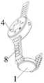
图1为本发明的立体图;Fig. 1 is the perspective view of the present invention;
图2为本发明的系统框图;Fig. 2 is the system block diagram of the present invention;
图3为本发明中脉搏传感的示意图;3 is a schematic diagram of pulse sensing in the present invention;
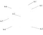
图4为本发明中交互器的正面示意图;Fig. 4 is the front schematic diagram of the interactor in the present invention;
具体实施方式Detailed ways
以下结合附图对本发明作进一步说明。The present invention will be further described below with reference to the accompanying drawings.
如图1和2所示,一种长时程且位置自检的脉搏检测仪,包括脉搏传感器1、信息放大传输电路2、供电电源3、交互器4、复位电路5、晶振电路6、控制器7、腕带8和松紧调节器。控制器7采用8051单片机。晶振电路6及复位电路5均与控制器7相连。供电电源3为脉搏传感器1、信息放大传输电路2、交互器4及控制器7供电。As shown in Figures 1 and 2, a long-term and position self-checking pulse detector includes a
如图2和3所示,脉搏传感器1包括检测壳体1-1、n根横向压电薄膜条1-2和n根纵向压电薄膜条1-3。n=16。横向压电薄膜条1-2及纵向压电薄膜条1-3的长度均为30mm。互相平行且间隔设置的n根纵向压电薄膜条1-3均设置在检测壳体1-1的内侧面。垂直于纵向压电薄膜条1-3且间隔设置的n根横向压电薄膜条1-2均与n根纵向压电薄膜条1-3固定。使得依次排列的n根横向压电薄膜条1-2和依次排列的n根纵向压电薄膜条1-3交错排列成网格状。压电薄膜条通过间隔设置,能够防止干扰电荷影响测量结果。检测过程中,横向压电薄膜条1-2与人手的腕部以上三指处贴合,用于接收脉搏信号的大小。纵向压电薄膜条1-3用于为脉搏传感器1的位置检测提供信息。As shown in FIGS. 2 and 3, the
信息放大传输电路2包括锁存器2-1、A/D转换电路2-2和放大器2-3。n根横向压电薄膜条1-2的信号输出端与锁存器2-1的n个输入引脚分别相连。锁存器2-1的n个输入引脚与n个放大器2-3的输入引脚分别相连。n根纵向压电薄膜条1-3的信号输出端与n个放大器2-3的输入引脚分别相连。锁存器2-1的使能引脚与控制器7相连。n个放大器2-3的输出引脚与数模转换器的n个模拟信号输入引脚分别相连。数模转换器的n个模拟信号输出引脚与控制器7的n个I/O分别相连。The information amplification and transmission circuit 2 includes a latch 2-1, an A/D conversion circuit 2-2, and an amplifier 2-3. The signal output terminals of the n lateral piezoelectric thin film strips 1-2 are respectively connected to the n input pins of the latch 2-1. The n input pins of the latch 2-1 are connected to the input pins of the n amplifiers 2-3, respectively. The signal output ends of the n vertical piezoelectric film strips 1-3 are respectively connected to the input pins of the n amplifiers 2-3. The enable pin of latch 2-1 is connected to
如图2和4所示,交互器4包括显示壳体4-1、蜂鸣器4-2、显示屏4-3、报警灯4-4、测量指示灯4-5、电源指示灯4-6和调整提示灯4-7。显示屏4-3设置在显示壳体4-1外侧面的中部。四个调整提示灯4-7均呈箭头状,且沿显示屏4-3的周向均布在显示壳体4-1上。报警灯4-4、测量指示灯4-5、电源指示灯4-6、蜂鸣器4-2均设置在显示壳体4-1的外侧面上。显示屏4-3、报警灯4-4、测量指示灯4-5、电源指示灯4-6及调整提示灯4-7均与控制器7相连。显示壳体4-1的两侧与检测壳体1-1的两侧分别通过腕带8连接。两根腕带8的内侧均设置有松紧调节器。松紧调节器采用压电陶瓷。其中一根腕带8通过两根扣合在一起的子腕带组成。As shown in Figures 2 and 4, the
该长时程且位置自检的脉搏检测仪的脉搏检测方法具体如下:The pulse detection method of the long-term and position self-checking pulse detector is as follows:
该长时程且位置自检的脉搏检测仪在使用前已用于多个健康的成年人,分别通过标准测量得到标准压力矩阵。标准压力矩阵由通过该长时程且位置自检的脉搏检测仪测得的n×n个脉搏压力值组成。标准压力矩阵内的最大值位于标准压力矩阵的中心处(即最大值是最中心的2×2矩阵中的一个元素)。所有标准压力矩阵内最大值,作为标准压力下限D1;所有标准压力矩阵内最小值,作为标准压力下限D2。D1~D2为脉搏压力峰值的正常范围。The long-term and position self-checking pulse detector has been used in a number of healthy adults before use, and a standard pressure matrix is obtained through standard measurement respectively. The standard pressure matrix consists of n×n pulse pressure values measured by the long-term and position self-checking pulse detector. The maximum value within the standard pressure matrix is located at the center of the standard pressure matrix (ie the maximum value is an element in the most central 2x2 matrix). The maximum value in all standard pressure matrices is taken as the standard pressure lower limit D1 ; the minimum value in all standard pressure matrices is taken as the standard pressure lower limit D2 . D1-D2 is the normal range of peak pulse pressure.
步骤一、使用者将显示壳体4-1、检测壳体1-1、两根腕带8连成的环形戴到腕部,并使得脉搏传感器1上的横向压电薄膜条1-2与使用者小臂内侧接触,横向压电薄膜条1-2的长度方向与使用者小臂的长度方向平行。以使用者的手掌到手背的方向作为观察方向,定义脉搏传感器的上、下、左、右四个方向,在观察方向上,上方、右方、下方、左方沿着顺时针方向依次排列。脉搏传感器的左方到右方的方向为使用者小臂到手掌的方向。对n根纵向压电薄膜条1-3沿着从左到右的方向依次排序。对n根横向压电薄膜条1-2沿着从上到下的方向依次排序。每隔d执行一次步骤二至十,且每隔T时间执行一次步骤十一,10s≤T≤100s。d为控制器7的采样周期,其取值为0.1s。
步骤二、n根横向压电薄膜条1-2和n根纵向压电薄膜条1-3受到因脉搏跳动而产生的压力,并将压力信号转化为模拟信号。n根横向压电薄膜条1-2将自身检测到的模拟信号传输给锁存器2-1。锁存器2-1将n根横向压电薄膜条1-2输出的模拟信号的峰值电压分别传输给n个放大器2-3。n根纵向压电薄膜条1-3将自身检测到的模拟信号分别传输给n个放大器2-3。n个放大器2-3将接收到的模拟信号分别放大后传输给数模转换器。数模转换器将接收到的n个放大后的模拟信号转化为n个数字信号后传输给控制器7。由于锁存器2-1将横向压电薄膜条1-2输出的电压最大值经延迟后传输给对应的放大器2-3。而纵向压电薄膜条1-3输出的电压直接传输给放大器2-3;故横向压电薄膜条1-2与纵向压电薄膜条1-3的电压最大值能够分别在不同时间到达对应的放大器2-3。使得控制器7能够分别采集各横向压电薄膜条1-2和纵向压电薄膜条1-3的电压最大值。Step 2: The n transverse piezoelectric thin film strips 1-2 and the n vertical piezoelectric thin film strips 1-3 are subjected to pressure generated by pulse beating, and the pressure signals are converted into analog signals. The n transverse piezoelectric thin film strips 1-2 transmit analog signals detected by themselves to the latch 2-1. The latch 2-1 transmits the peak voltages of the analog signals output by the n lateral piezoelectric thin film strips 1-2 to the n amplifiers 2-3 respectively. The n longitudinal piezoelectric thin film strips 1-3 respectively transmit the analog signals detected by themselves to the n amplifiers 2-3. The n amplifiers 2-3 respectively amplify the received analog signals and transmit them to the digital-to-analog converter. The digital-to-analog converter converts the received n amplified analog signals into n digital signals and transmits them to the
步骤三、数据处理。Step three, data processing.
3-1.建立横向电荷量集合Q1和纵向电荷量集合Q2如下:3-1. Establish the lateral charge amount set Q1 and the vertical charge amount set Q2 as follows:
Q1={q11,q12,...,q1n}Q1 ={q11 ,q12 ,...,q1n }
Q2={q21,q22,...,q2n}Q2 ={q21 ,q22 ,...,q2n }
其中,s1k为第k根横向压电薄膜条1-2输出的电压最大值;s2k为第k根纵向压电薄膜条1-3输出的电压最大值;k=1,2,…,n。Among them, s1k is the maximum voltage output by the k-th transverse piezoelectric thin-film strip 1-2; s2k is the maximum voltage output by the k-th longitudinal piezoelectric thin-film strip 1-3; k=1,2,…, n.
根据横向电荷量集合Q1和纵向电荷量集合Q2,建立二维电荷量集合Q′According to the lateral charge quantity set Q1 and the vertical charge quantity set Q2 , a two-dimensional charge quantity set Q′ is established

其中,s′ij=s1i+s2j;i=1,2,…,n;j=1,2,…,n。Wherein, s′ij =s1i +s2j ; i=1,2,...,n; j=1,2,...,n.
3-2.建立二维电压集合U。3-2. Establish a two-dimensional voltage set U.

其中,
3-3.建立脉搏压力矩阵F3-3. Establish pulse pressure matrix F

其中,

步骤四、将脉搏压力矩阵F内的最大值称为Fab;通过禁忌算法确定Fab的下标a、b。a表示Fab在脉搏压力矩阵F中的行序号;b表示Fab在脉搏压力矩阵F中的列序号;Fab为第a根横向压电薄膜条1-2和第b根纵向压电薄膜条1-3交点处受到的压力值。若

步骤五、四个测量指示灯分别为上指示灯、下指示灯、左指示灯、右指示灯。上指示灯与脉搏传感器的下方对齐(由于交互器4与脉搏传感器分别位于手腕的两侧,故交互器4的上方即为脉搏传感器的下方)。下指示灯与脉搏传感器的上方对齐。左指示灯与脉搏传感器的左方对齐。右指示灯与脉搏传感器的右方对齐。若


步骤六、判断检测到脉搏压力矩阵F是否正常,并选择位移补偿方式。Step 6: Determine whether the detected pulse pressure matrix F is normal, and select the displacement compensation method.
6-1.提取脉搏压力矩阵F的最大中心5×5阵列,并提取一个标准压力矩阵的最大中心5×5阵列。一个矩阵的最大中心5×5阵列表示以该矩阵的最大值为中心的5×5的矩阵。6-1. Extract the
标准压力矩阵有多个,是通过提前测量得到,获取方法如下:挑选t名脉搏正常的成年人,t>100,利用将脉搏传感器贴合到这些成年人小臂上正确的位置对进行标准的脉搏测量,得到的各脉搏压力矩阵即为标准压力矩阵。各标准压力矩阵储存在控制器7的存储器中,并命名为Si(i=1,2...t)。There are multiple standard pressure matrices, which are obtained by measuring in advance. The acquisition method is as follows: Select t adults with normal pulses, t>100, and use the pulse sensor to fit the correct position of these adults on the forearm. Pulse measurement, the obtained pulse pressure matrix is the standard pressure matrix. Each standard pressure matrix is stored in the memory of the
将脉搏压力矩阵F的最大中心5×5阵列减去标准压力矩阵的最大中心5×5阵列,得到5×5的偏差矩阵。若偏差矩阵内所有元素的平方和小于0.3,则进入步骤6-2;否则,显示屏4-3提示使用者重新检测。Subtract the
6-2.判断脉搏压力矩阵F内的最大值Fab是否在D1~D2的范围内。D1~D2为脉搏压力峰值的正常范围。若脉搏压力矩阵F内的最大值在D1~D2的范围内,则执行步骤七;否则执行步骤八和九。6-2. Determine whether the maximum value Fab in the pulse pressure matrix F is within the range of D1 to D2 . D1-D2 is the normal range of peak pulse pressure. If the maximum value in the pulse pressure matrix F is within the range of D1 to D2 , go to
步骤七、小位移补偿。
7-1.若
若
7-2.若
若
7-3.进入步骤十。7-3. Go to step ten.
步骤八、大位移补偿:
8-1.将1赋值给i。8-1. Assign 1 to i.
8-2.计算步骤三所得的脉搏压力矩阵F与第i个标准压力矩阵Si的比例调整参数hi=(si,max-Fab)/si,max。si,max为第i个标准压力矩阵Si内的最大值。si,max在第i个标准压力矩阵Si内所处的行序号为xi,所处的列序号为yi。各标准压力矩阵均为提前测量得到。8-2. Calculating the ratio of the pulse pressure matrix F obtained in
将脉搏压力矩阵F的最大值Fab的坐标位置与第i个标准压力矩阵Si的最大值si,max的坐标位置对齐后,取脉搏压力矩阵F与第i个标准压力矩阵Si的相交部分。在脉搏压力矩阵F截取出矩阵Fi′。在第i个标准压力矩阵Si截取出矩阵S′i。After aligning the coordinate position of the maximum value Fab of the pulse pressure matrix F with the coordinate position of the maximum valuesi,max of theith standard pressure matrix Si, take the difference between the pulse pressure matrix F and theith standard pressure matrix Si. intersecting part. The matrix Fi ' is cut out from the pulse pressure matrix F. The matrix S′i is cut out from the i-th standard pressure matrix S i.
若a≤xi且b≤yi,则矩阵Fi′为脉搏压力矩阵F的第一行至第a+n-xi行与第一列至第b+n-yi列的相交区域;矩阵S′i为第i个标准压力矩阵Si的第xi-a+1行至第n行与第yi-b+1列至第n列的相交区域。If a≤xi and b≤yi , the matrix Fi ' is the intersection area of the first row to a+nxi row and the first column to b+nyi column of the pulse pressure matrix F; the matrix S'i is the intersection area of the ith standard pressure matrix Si from thexi -a+1th row to the nth row and theyi -b+1th column to the nth column.
若a≤xi且b>yi,则矩阵Fi′为脉搏压力矩阵F的第一行至第a+n-xi行与第b-yi+1列至第n列的相交区域;矩阵S′i为第i个标准压力矩阵Si的第xi-a+1行至第n行与第一列至第yi+n-b列的相交区域。If a≤xi and b>yi , the matrix Fi ' is the intersection area of the first row to a+nxi row and byi +1 column to nth column of the pulse pressure matrix F; the matrix S'i is the intersection area of the ith standard pressure matrix Si from thexi -a+1th row to the nth row and the first column to the yi +nbth column.
若a>xi且b≤yi,则矩阵Fi′为脉搏压力矩阵F的第a-xi+1行至第n行与第一列至第b+n-yi列的相交区域;矩阵S′i为第i个标准压力矩阵Si的第一行至第xi+n-a行与第yi-b+1列至第n列的相交区域。If a>xi and b≤yi , the matrix Fi ' is the intersection area of theaxi+1th row to nth row and the first column to b+ny ithcolumn of the pulse pressure matrix F; the matrix S'i is the intersection area of theith standard pressure matrix Si from the first row to the xi +na th row and theyi -b+1 th column to the n th column.
若a>xi且b>yi,则矩阵Fi′为脉搏压力矩阵F的第a-xi+1行至第n行与第b-yi+1列至第n列的相交区域;矩阵S′i为第i个标准压力矩阵Si的第一行至第xi+n-a行与第n行与第一列至第yi+n-b列的相交区域。If a>xi and b>yi , then the matrix Fi ' is the intersection area of theaxi +1th row to nth row and by i+ 1th column to nth column of the pulse pressure matrix F; matrix S'i is the intersection area of theith standard pressure matrix Si from the first row to thexi +na th row and the nth row and the first column to the yi +nb th column.
8-3.定义步骤8-2所得的矩阵Fi′内元素f′与矩阵S′i上与f′对应位置元素s′的相关系数γ=|f′-hi×s′|。f′在矩阵Fi′上的行序号等于s′在矩阵S′i上的行序号。f′在矩阵Fi′上的列序号等于s′在矩阵S′i上的列序号。之后进入步骤8-4。8-3. Define the correlation coefficient γ=|f'-hi ×s'| between the element f' in the matrix Fi ' obtained in step 8-2 and the element s' at the position corresponding to f' on the matrix S'i . The row number of f' on matrix Fi ' is equal to the row number of s' on matrix S'i . The column number of f' on matrix Fi ' is equal to the column number of s' on matrix S'i . Then go to step 8-4.
8-4.若矩阵Fi′上所有位置的元素与矩阵S′i上对应位置的元素的相关系数均小于阈值Y,则脉搏压力矩阵F与第i个标准压力矩阵Si相匹配,将第i个标准压力矩阵Si作为特征压力矩阵,将比例调整参数hi作为最终调节系数h,并进入步骤8-5;否则,将i增大1后,重复步骤8-2和8-3。若所有标准压力矩阵均无法与脉搏压力矩阵F相匹配,则不输出结果,仅提醒使用者调整脉搏传感器位置。8-4. If the correlation coefficients between the elements of all positions on the matrix Fi ′ and the elements of the corresponding positions on the matrix S′i are smaller than the threshold Y, then the pulse pressure matrix F matches the i-th standard pressure matrix Si , and the The i-th standard pressure matrix Si is used as the characteristic pressure matrix, and the proportional adjustment parameter hi is used as the final adjustment coefficient h, and go to step 8-5; otherwise, after increasing i by 1, repeat steps 8-2 and 8-3 . If all standard pressure matrices cannot match the pulse pressure matrix F, no result is output, and the user is only reminded to adjust the position of the pulse sensor.
8-5.若a≤xi且b≤yi,则将特征压力矩阵中第xi-a行至第n行与第yi-b列至第n列的相交区域替换为脉搏压力矩阵F的第一行至第a+n-xi行与第一列至第b+n-yi列的相交区域。8-5. If a≤xi and b≤yi , replace the intersection area between the xi -a row to the nth row and theyi -b column to the nth column in the characteristic pressure matrix with the pulse pressure matrix The intersection area of the first row to the a+nxi -th row of F and the first column to the b+nyi -th column.
若a≤xi且b>yi,则将特征压力矩阵中第xi-a行至第n行与第一列至第yi+n-b列的相交区域替换为脉搏压力矩阵F的第一行至第a+n-xi行与第yi-b列至第n列的相交区域。If a≤xi and b>yi , replace the intersection area between the xi -a row to nth row and the first column to yi +nb column in the characteristic pressure matrix with the first value of the pulse pressure matrix F Line to the intersection of line a+nxi and column yi -b to column n.
若a>xi且b≤yi,则将特征压力矩阵中第一行至第xi+n-a行与第yi-b列至第n列的相交区域替换为脉搏压力矩阵F的第a-xi行至第n行与第一列至第b+n-yi列的相交区域。If a>xi and b≤yi , replace the intersection area of the first row to xi +na row and yi -b column to nth column in the characteristic pressure matrix with the ax of the pulse pressure matrix F The intersection area of rowi to row n and
若a>xi且b>yi,则将特征压力矩阵中第一行至第xi+n-a行与第一列至第yi+n-b列的相交区域替换为脉搏压力矩阵F的第a-xi行至第n行与第yi-b列至第n列的相交区域。If a>xi and b>yi , replace the intersection area of the first row to xi +na row and the first column to yi +nb column in the characteristic pressure matrix with the ax of the pulse pressure matrix F The intersection area of rowi to row n and column yi -b to column n.
步骤九、将脉搏压力矩阵F替换为步骤八所得的特征压力矩阵。之后进入步骤十。Step 9: Replace the pulse pressure matrix F with the characteristic pressure matrix obtained in
步骤十、将脉搏压力矩阵F内的各元素在一个空间直角坐标系中进行描点,得到n2个离散点,由于表带的自感知压紧作用,使得测量的压力值和血压之间的损耗极小,所以对脉搏压力矩阵F中压力值直接进行描点。空间直角坐标系的横坐标、纵坐标表示点在脉搏传感器上的位置。将空间直角坐标系中的n2个离散点拟合为脉搏特征曲面,并求出所得脉搏特征曲面中z轴最大值。脉搏特征曲面能够完整描述使用者当前的脉搏状况。脉搏特征曲面的z轴最大值为当前的脉搏峰值。Step 10. Plot the elements in the pulse pressure matrix F in a space rectangular coordinate system to obtain n2 discrete points. Due to the self-perceived pressing effect of the strap, the loss between the measured pressure value and the blood pressure is caused. is extremely small, so the pressure values in the pulse pressure matrix F are directly traced. The abscissa and ordinate of the space rectangular coordinate system represent the position of the point on the pulse sensor. The n2 discrete points in the space rectangular coordinate system are fitted to the pulse characteristic surface, and the maximum value of the z-axis in the obtained pulse characteristic surface is obtained. The pulse characteristic surface can completely describe the current pulse condition of the user. The z-axis maximum value of the pulse feature surface is the current pulse peak value.
步骤十一、将前T时长内所得的所有脉搏特征曲面中z轴最大值绘入横坐标为时间,纵坐标为压力值的平面之间坐标系中,得到脉搏曲线图;求出脉搏曲线图中有效峰值的个数l。有效峰值表示大于曲线最大值的80%的峰值。计算脉搏频率f=l/T。Step 11: Plot the maximum value of the z-axis in all the pulse characteristic surfaces obtained within the first T duration into the coordinate system between the planes where the abscissa is the time and the ordinate is the pressure value to obtain a pulse curve; find the pulse curve The number of valid peaks in l. Valid peaks represent peaks greater than 80% of the maximum value of the curve. Calculate the pulse rate f=l/T.
Claims (8)


Priority Applications (1)
| Application Number | Priority Date | Filing Date | Title |
|---|---|---|---|
| CN201910081071.1ACN109645967B (en) | 2019-01-28 | 2019-01-28 | Long-term and position self-checking pulse detector and pulse detection method thereof |
Applications Claiming Priority (1)
| Application Number | Priority Date | Filing Date | Title |
|---|---|---|---|
| CN201910081071.1ACN109645967B (en) | 2019-01-28 | 2019-01-28 | Long-term and position self-checking pulse detector and pulse detection method thereof |
Publications (2)
| Publication Number | Publication Date |
|---|---|
| CN109645967A CN109645967A (en) | 2019-04-19 |
| CN109645967Btrue CN109645967B (en) | 2021-04-30 |
Family
ID=66120935
Family Applications (1)
| Application Number | Title | Priority Date | Filing Date |
|---|---|---|---|
| CN201910081071.1AActiveCN109645967B (en) | 2019-01-28 | 2019-01-28 | Long-term and position self-checking pulse detector and pulse detection method thereof |
Country Status (1)
| Country | Link |
|---|---|
| CN (1) | CN109645967B (en) |
Families Citing this family (1)
| Publication number | Priority date | Publication date | Assignee | Title |
|---|---|---|---|---|
| CN110367994B (en)* | 2019-08-16 | 2021-09-07 | 福建工程学院 | Piezoelectric matrix active monitoring device for gait and its working method |
Citations (11)
| Publication number | Priority date | Publication date | Assignee | Title |
|---|---|---|---|---|
| JP2002330933A (en)* | 2001-04-25 | 2002-11-19 | Sonfun An | Instrument for measuring quantity of motion |
| CN102551696A (en)* | 2011-12-23 | 2012-07-11 | 天津大学 | Multipath pulse condition detection device based on flexible array sensor |
| CN202568218U (en)* | 2012-03-06 | 2012-12-05 | 河南海王星科技发展有限公司 | Pulse condition measurement contact based on array-type pressure sensor |
| CN203000918U (en)* | 2012-12-25 | 2013-06-19 | 沈阳市威灵医用电子有限公司 | Non-invasive blood pressure continuous monitoring system based on pulse waves |
| CN104000567A (en)* | 2014-06-13 | 2014-08-27 | 河海大学常州校区 | Portable multipoint pulse wireless monitoring system |
| KR20150008611A (en)* | 2013-07-15 | 2015-01-23 | 한국산업기술대학교산학협력단 | Apparatus of sensing physiological signal with wearing on the wrist and method of detecting emergency situation using this |
| CN105011918A (en)* | 2015-08-12 | 2015-11-04 | 湖北科技学院 | Quick pulse wave detection system, detection method and detection program |
| CN105323337A (en)* | 2014-06-05 | 2016-02-10 | Lg电子株式会社 | Watch type mobile terminal |
| CN105358055A (en)* | 2013-07-12 | 2016-02-24 | 墨尔本皇家理工大学 | Sensor array system |
| CN206355041U (en)* | 2016-07-28 | 2017-07-28 | 广东石油化工学院 | Pulses measure instrument |
| CN108577858A (en)* | 2018-04-08 | 2018-09-28 | 博联众科(武汉)科技有限公司 | The automatic judging method and system at a kind of tissue oxygenation saturation degree monitoring position |
Family Cites Families (1)
| Publication number | Priority date | Publication date | Assignee | Title |
|---|---|---|---|---|
| US7558622B2 (en)* | 2006-05-24 | 2009-07-07 | Bao Tran | Mesh network stroke monitoring appliance |
- 2019
- 2019-01-28CNCN201910081071.1Apatent/CN109645967B/enactiveActive
Patent Citations (11)
| Publication number | Priority date | Publication date | Assignee | Title |
|---|---|---|---|---|
| JP2002330933A (en)* | 2001-04-25 | 2002-11-19 | Sonfun An | Instrument for measuring quantity of motion |
| CN102551696A (en)* | 2011-12-23 | 2012-07-11 | 天津大学 | Multipath pulse condition detection device based on flexible array sensor |
| CN202568218U (en)* | 2012-03-06 | 2012-12-05 | 河南海王星科技发展有限公司 | Pulse condition measurement contact based on array-type pressure sensor |
| CN203000918U (en)* | 2012-12-25 | 2013-06-19 | 沈阳市威灵医用电子有限公司 | Non-invasive blood pressure continuous monitoring system based on pulse waves |
| CN105358055A (en)* | 2013-07-12 | 2016-02-24 | 墨尔本皇家理工大学 | Sensor array system |
| KR20150008611A (en)* | 2013-07-15 | 2015-01-23 | 한국산업기술대학교산학협력단 | Apparatus of sensing physiological signal with wearing on the wrist and method of detecting emergency situation using this |
| CN105323337A (en)* | 2014-06-05 | 2016-02-10 | Lg电子株式会社 | Watch type mobile terminal |
| CN104000567A (en)* | 2014-06-13 | 2014-08-27 | 河海大学常州校区 | Portable multipoint pulse wireless monitoring system |
| CN105011918A (en)* | 2015-08-12 | 2015-11-04 | 湖北科技学院 | Quick pulse wave detection system, detection method and detection program |
| CN206355041U (en)* | 2016-07-28 | 2017-07-28 | 广东石油化工学院 | Pulses measure instrument |
| CN108577858A (en)* | 2018-04-08 | 2018-09-28 | 博联众科(武汉)科技有限公司 | The automatic judging method and system at a kind of tissue oxygenation saturation degree monitoring position |
Also Published As
| Publication number | Publication date |
|---|---|
| CN109645967A (en) | 2019-04-19 |
Similar Documents
| Publication | Publication Date | Title |
|---|---|---|
| US4757453A (en) | Body activity monitor using piezoelectric transducers on arms and legs | |
| Woakes et al. | Implantable data logging system for heart rate and body temperature: its application to the estimation of field metabolic rates in Antarctic predators | |
| US3906931A (en) | Device for the determination and the automatic real time computation of the parameters of man{3 s stability of stance | |
| US20210345877A1 (en) | Method and device for self-measurement of intra-ocular pressure | |
| US11612329B2 (en) | Method and system for adjusting output signal of pulse diagnosis device, storage device, and control device | |
| CN104220859B (en) | System for testing palm grip strength | |
| CN103637787A (en) | Real-time blood pressure measuring device and method for measuring pulse wave transmission time difference in real time | |
| JPH01501210A (en) | Blood pressure monitoring method and device | |
| CN106725363B (en) | Pulse wave acquisition device and pulse wave acquisition calibration method | |
| CN110974242B (en) | Gait abnormal degree evaluation method for wearable device and wearable device | |
| CN103637788A (en) | Real-time blood pressure measuring device | |
| CN109645967B (en) | Long-term and position self-checking pulse detector and pulse detection method thereof | |
| CN208968648U (en) | A kind of high-precision electronic claims | |
| US4164937A (en) | Equipment for detecting, monitoring, measuring, displaying and recording pulse and heartbeat | |
| CN111493454A (en) | A kind of weight measurement insole, shoe, system and weight measurement method | |
| CN207024047U (en) | A kind of Intelligent bracelet for carrying out wearing adjustment | |
| Choudhury et al. | A novel modular tonometry-based device to measure pulse pressure waveforms in radial artery | |
| Kumar et al. | Design, Development and Analysis of an Image Processing Based Advanced System for Testing, Calibration and Type Approval of Blood Pressure Devices | |
| CN2198871Y (en) | human body physiological parameter recorder | |
| Chethana et al. | Design and development of optical sensor based ground reaction force measurement platform for gait and geriatric studies | |
| CN110200634A (en) | A kind of plantar pressure sensor that frequency of amendment influences and corresponding modification method | |
| CN220369981U (en) | Balance evaluation device | |
| CN211094070U (en) | Simple blood pressure measuring device based on flat tension method | |
| CN215227575U (en) | Wearable FFR value detection device | |
| Terekhov | Instrumentation for automatic measurement and real-time evaluation of man's postural equilibrium |
Legal Events
| Date | Code | Title | Description |
|---|---|---|---|
| PB01 | Publication | ||
| PB01 | Publication | ||
| SE01 | Entry into force of request for substantive examination | ||
| SE01 | Entry into force of request for substantive examination | ||
| GR01 | Patent grant | ||
| GR01 | Patent grant | ||
| TR01 | Transfer of patent right | ||
| TR01 | Transfer of patent right | Effective date of registration:20220527 Address after:310030 Building 1, 329 Jinpeng street, Sandun Town, Xihu District, Hangzhou City, Zhejiang Province Patentee after:HANGZHOU D. A. GENETIC ENGINEERING Co.,Ltd. Address before:310018 No. 2 street, Xiasha Higher Education Zone, Hangzhou, Zhejiang Patentee before:HANGZHOU DIANZI University |