CN109640920B - Safe drug transfer system - Google Patents
Safe drug transfer systemDownload PDFInfo
- Publication number
- CN109640920B CN109640920BCN201780051252.9ACN201780051252ACN109640920BCN 109640920 BCN109640920 BCN 109640920BCN 201780051252 ACN201780051252 ACN 201780051252ACN 109640920 BCN109640920 BCN 109640920B
- Authority
- CN
- China
- Prior art keywords
- needle
- vial
- bottle
- adapter
- vial adapter
- Prior art date
- Legal status (The legal status is an assumption and is not a legal conclusion. Google has not performed a legal analysis and makes no representation as to the accuracy of the status listed.)
- Active
Links
Images


Classifications
- A—HUMAN NECESSITIES
- A61—MEDICAL OR VETERINARY SCIENCE; HYGIENE
- A61J—CONTAINERS SPECIALLY ADAPTED FOR MEDICAL OR PHARMACEUTICAL PURPOSES; DEVICES OR METHODS SPECIALLY ADAPTED FOR BRINGING PHARMACEUTICAL PRODUCTS INTO PARTICULAR PHYSICAL OR ADMINISTERING FORMS; DEVICES FOR ADMINISTERING FOOD OR MEDICINES ORALLY; BABY COMFORTERS; DEVICES FOR RECEIVING SPITTLE
- A61J1/00—Containers specially adapted for medical or pharmaceutical purposes
- A61J1/14—Details; Accessories therefor
- A61J1/20—Arrangements for transferring or mixing fluids, e.g. from vial to syringe
- A61J1/2096—Combination of a vial and a syringe for transferring or mixing their contents
- A—HUMAN NECESSITIES
- A61—MEDICAL OR VETERINARY SCIENCE; HYGIENE
- A61J—CONTAINERS SPECIALLY ADAPTED FOR MEDICAL OR PHARMACEUTICAL PURPOSES; DEVICES OR METHODS SPECIALLY ADAPTED FOR BRINGING PHARMACEUTICAL PRODUCTS INTO PARTICULAR PHYSICAL OR ADMINISTERING FORMS; DEVICES FOR ADMINISTERING FOOD OR MEDICINES ORALLY; BABY COMFORTERS; DEVICES FOR RECEIVING SPITTLE
- A61J1/00—Containers specially adapted for medical or pharmaceutical purposes
- A61J1/14—Details; Accessories therefor
- A61J1/16—Holders for containers
- A—HUMAN NECESSITIES
- A61—MEDICAL OR VETERINARY SCIENCE; HYGIENE
- A61M—DEVICES FOR INTRODUCING MEDIA INTO, OR ONTO, THE BODY; DEVICES FOR TRANSDUCING BODY MEDIA OR FOR TAKING MEDIA FROM THE BODY; DEVICES FOR PRODUCING OR ENDING SLEEP OR STUPOR
- A61M5/00—Devices for bringing media into the body in a subcutaneous, intra-vascular or intramuscular way; Accessories therefor, e.g. filling or cleaning devices, arm-rests
- A61M5/178—Syringes
- A61M5/1782—Devices aiding filling of syringes in situ
- A—HUMAN NECESSITIES
- A61—MEDICAL OR VETERINARY SCIENCE; HYGIENE
- A61J—CONTAINERS SPECIALLY ADAPTED FOR MEDICAL OR PHARMACEUTICAL PURPOSES; DEVICES OR METHODS SPECIALLY ADAPTED FOR BRINGING PHARMACEUTICAL PRODUCTS INTO PARTICULAR PHYSICAL OR ADMINISTERING FORMS; DEVICES FOR ADMINISTERING FOOD OR MEDICINES ORALLY; BABY COMFORTERS; DEVICES FOR RECEIVING SPITTLE
- A61J1/00—Containers specially adapted for medical or pharmaceutical purposes
- A61J1/14—Details; Accessories therefor
- A61J1/1443—Containers with means for dispensing liquid medicaments in a filtered or sterile way, e.g. with bacterial filters
- A—HUMAN NECESSITIES
- A61—MEDICAL OR VETERINARY SCIENCE; HYGIENE
- A61J—CONTAINERS SPECIALLY ADAPTED FOR MEDICAL OR PHARMACEUTICAL PURPOSES; DEVICES OR METHODS SPECIALLY ADAPTED FOR BRINGING PHARMACEUTICAL PRODUCTS INTO PARTICULAR PHYSICAL OR ADMINISTERING FORMS; DEVICES FOR ADMINISTERING FOOD OR MEDICINES ORALLY; BABY COMFORTERS; DEVICES FOR RECEIVING SPITTLE
- A61J1/00—Containers specially adapted for medical or pharmaceutical purposes
- A61J1/14—Details; Accessories therefor
- A61J1/20—Arrangements for transferring or mixing fluids, e.g. from vial to syringe
- A61J1/2003—Accessories used in combination with means for transfer or mixing of fluids, e.g. for activating fluid flow, separating fluids, filtering fluid or venting
- A61J1/2006—Piercing means
- A61J1/201—Piercing means having one piercing end
- A—HUMAN NECESSITIES
- A61—MEDICAL OR VETERINARY SCIENCE; HYGIENE
- A61J—CONTAINERS SPECIALLY ADAPTED FOR MEDICAL OR PHARMACEUTICAL PURPOSES; DEVICES OR METHODS SPECIALLY ADAPTED FOR BRINGING PHARMACEUTICAL PRODUCTS INTO PARTICULAR PHYSICAL OR ADMINISTERING FORMS; DEVICES FOR ADMINISTERING FOOD OR MEDICINES ORALLY; BABY COMFORTERS; DEVICES FOR RECEIVING SPITTLE
- A61J1/00—Containers specially adapted for medical or pharmaceutical purposes
- A61J1/14—Details; Accessories therefor
- A61J1/20—Arrangements for transferring or mixing fluids, e.g. from vial to syringe
- A61J1/2003—Accessories used in combination with means for transfer or mixing of fluids, e.g. for activating fluid flow, separating fluids, filtering fluid or venting
- A61J1/2048—Connecting means
- A61J1/2058—Connecting means having multiple connecting ports
- A—HUMAN NECESSITIES
- A61—MEDICAL OR VETERINARY SCIENCE; HYGIENE
- A61J—CONTAINERS SPECIALLY ADAPTED FOR MEDICAL OR PHARMACEUTICAL PURPOSES; DEVICES OR METHODS SPECIALLY ADAPTED FOR BRINGING PHARMACEUTICAL PRODUCTS INTO PARTICULAR PHYSICAL OR ADMINISTERING FORMS; DEVICES FOR ADMINISTERING FOOD OR MEDICINES ORALLY; BABY COMFORTERS; DEVICES FOR RECEIVING SPITTLE
- A61J1/00—Containers specially adapted for medical or pharmaceutical purposes
- A61J1/14—Details; Accessories therefor
- A61J1/20—Arrangements for transferring or mixing fluids, e.g. from vial to syringe
- A61J1/2003—Accessories used in combination with means for transfer or mixing of fluids, e.g. for activating fluid flow, separating fluids, filtering fluid or venting
- A61J1/2048—Connecting means
- A61J1/2065—Connecting means having aligning and guiding means
- A—HUMAN NECESSITIES
- A61—MEDICAL OR VETERINARY SCIENCE; HYGIENE
- A61J—CONTAINERS SPECIALLY ADAPTED FOR MEDICAL OR PHARMACEUTICAL PURPOSES; DEVICES OR METHODS SPECIALLY ADAPTED FOR BRINGING PHARMACEUTICAL PRODUCTS INTO PARTICULAR PHYSICAL OR ADMINISTERING FORMS; DEVICES FOR ADMINISTERING FOOD OR MEDICINES ORALLY; BABY COMFORTERS; DEVICES FOR RECEIVING SPITTLE
- A61J1/00—Containers specially adapted for medical or pharmaceutical purposes
- A61J1/14—Details; Accessories therefor
- A61J1/20—Arrangements for transferring or mixing fluids, e.g. from vial to syringe
- A61J1/2089—Containers or vials which are to be joined to each other in order to mix their contents
- A—HUMAN NECESSITIES
- A61—MEDICAL OR VETERINARY SCIENCE; HYGIENE
- A61M—DEVICES FOR INTRODUCING MEDIA INTO, OR ONTO, THE BODY; DEVICES FOR TRANSDUCING BODY MEDIA OR FOR TAKING MEDIA FROM THE BODY; DEVICES FOR PRODUCING OR ENDING SLEEP OR STUPOR
- A61M39/00—Tubes, tube connectors, tube couplings, valves, access sites or the like, specially adapted for medical use
- A61M39/10—Tube connectors; Tube couplings
- A61M2039/1077—Adapters, e.g. couplings adapting a connector to one or several other connectors
Landscapes
- Health & Medical Sciences (AREA)
- Veterinary Medicine (AREA)
- Life Sciences & Earth Sciences (AREA)
- Animal Behavior & Ethology (AREA)
- General Health & Medical Sciences (AREA)
- Public Health (AREA)
- Pharmacology & Pharmacy (AREA)
- Engineering & Computer Science (AREA)
- Vascular Medicine (AREA)
- Anesthesiology (AREA)
- Biomedical Technology (AREA)
- Heart & Thoracic Surgery (AREA)
- Hematology (AREA)
- Medical Preparation Storing Or Oral Administration Devices (AREA)
- Infusion, Injection, And Reservoir Apparatuses (AREA)
Abstract
Description
Translated fromChinese相关申请的交叉引用CROSS-REFERENCE TO RELATED APPLICATIONS
本申请要求2016年8月22日提交的序列号为62/377,853的美国临时专利申请的优先权,其公开内容的全文通过引用明确地并入本文中。This application claims priority to US Provisional Patent Application Serial No. 62/377,853, filed August 22, 2016, the disclosure of which is expressly incorporated herein by reference in its entirety.
技术领域technical field
本公开涉及一种用于以安全的方式转移药物的系统,以及一种使用该系统的方法。The present disclosure relates to a system for transferring a drug in a safe manner, and a method of using the system.
背景技术Background technique
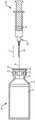
图1示出了构造成保持药物11(例如胰岛素或另一种药物)的瓶10。说明性的瓶10包括相对宽的凸缘或边缘12、在凸缘12下方的相对窄的颈部14,以及在颈部14下方变宽的倾斜的肩部16。说明性的瓶10的上端还包括密封和保护瓶10中的药物的间隔件或塞子18(例如,橡胶塞)。塞子18的横截面可以是大体上T形,使得塞子18搁置在瓶10的凸缘12上方,并且朝向颈部14向下延伸到瓶10中。凸缘12包括(例如,铝材料的)卷边密封件17,其围绕凸缘12和塞子18延伸,以将塞子18固定到瓶10,同时为针22提供到达塞子18的顶部途径。保护盖或帽19在塞子18上方联接到瓶10的顶部,并且在用针22刺穿塞子18之前,例如由使用者的手指将其移除。Figure 1 shows a
图1也示出了传统的注射器20。说明性的注射器20包括柱塞24和针22,该针22沿着轴线A从注射器20突出长度L。注射器20包括位于远端的针座23,其将针22固定到注射器20。带有针22的针座23可以例如通过标准化连接件(例如,
瓶10中药物的浓度可以变化。对于胰岛素,例如,瓶10可能包含每毫升(mL)液体100单位胰岛素(即U-100胰岛素)、每mL液体200单位胰岛素(即U-200胰岛素)、每mL液体500单位胰岛素(即U-500胰岛素)或其它合适的胰岛素浓度。较高浓度的药物对患者可能具有某些优点,例如延长的使用时间和较小的输送装置。然而,如果较高浓度的药物被误认为是低浓度药物,则患者可能易受药物过量或低血糖的影响。The concentration of drug in
发明内容SUMMARY OF THE INVENTION
本公开提供了一种瓶适配器和针组件,其构造成与容纳药物(例如胰岛素)的瓶/小瓶/药瓶一起使用。瓶适配器可以包括针开口,其构造成接纳几何上对应的针组件针座的针,从而以安全的方式从瓶中抽出药物。瓶适配器还可以包括清洁通道,其构造成接纳清洁装置,以清洁瓶的塞子,同时阻止针穿过清洁通道到达塞子。在一些实施例中,瓶适配器构造成降低使用者将不正确的浓度的胰岛素转移到输送装置中的可能性。The present disclosure provides a vial adapter and needle assembly configured for use with a vial/vial/vial containing a drug (eg, insulin). The vial adapter may include a needle opening configured to receive a needle of a geometrically corresponding needle assembly needle hub to withdraw the drug from the vial in a safe manner. The bottle adapter may also include a cleaning channel configured to receive a cleaning device to clean the stopper of the bottle while preventing the needle from passing through the cleaning channel to the stopper. In some embodiments, the vial adapter is configured to reduce the likelihood of a user transferring an incorrect concentration of insulin into the delivery device.
根据本公开的一个实施例,提供了一种瓶适配器,其用于与容纳含药物的瓶和具有针的针组件一起使用。瓶适配器包括:基本上中空的主体,其构造成与瓶联接;在所述主体中的针开口,该针开口沿着轴线布置,并且其尺寸和形状确定成沿着轴线接纳针,以从瓶中抽取药物;主体中的清洁通道,该清洁通道的尺寸和形状确定成接纳清洁装置以清洁瓶;和罩盖,其从主体向外延伸,以阻止针通过清洁通道插入瓶中。According to one embodiment of the present disclosure, a vial adapter is provided for use with a vial containing a drug and a needle assembly with a needle. The bottle adapter includes: a substantially hollow body configured to couple with the bottle; a needle opening in the body, the needle opening disposed along the axis and sized and shaped to receive the needle along the axis to remove the needle from the bottle a cleaning channel in the body sized and shaped to receive a cleaning device to clean the bottle; and a cover extending outwardly from the body to prevent insertion of the needle into the bottle through the cleaning channel.
在某些实施例中,主体的下端包括大体上筒形的侧壁,并且主体的上端包括上壁,罩盖径向向外延伸超过主体下端的筒形的侧壁。In certain embodiments, the lower end of the body includes a generally cylindrical side wall, and the upper end of the body includes an upper wall, and the cover extends radially outward beyond the cylindrical side wall of the lower end of the body.
在某些实施例中,罩盖从主体的上壁连续地延伸。In certain embodiments, the cover extends continuously from the upper wall of the body.
在某些实施例中,罩盖从针开口的轴线延伸约20毫米至约30毫米的距离。In certain embodiments, the cover extends a distance of about 20 millimeters to about 30 millimeters from the axis of the needle opening.
在某些实施例中,清洁通道在大于50度的第一角度和小于150度的第二角度之间偏离针开口的轴线。第一角度可以是约60度至约70度,第二角度可以是约110度至约120度。In certain embodiments, the cleaning channel is offset from the axis of the needle opening between a first angle greater than 50 degrees and a second angle less than 150 degrees. The first angle may be about 60 degrees to about 70 degrees, and the second angle may be about 110 degrees to about 120 degrees.
在某些实施例中,清洁通道的入口位于主体的侧壁上,该侧壁从主体的下端径向向外延伸到主体的上端,使得清洁通道的入口也从入口的下端径向向外延伸到入口的上端。In certain embodiments, the inlet to the cleaning channel is located on a sidewall of the body that extends radially outward from the lower end of the body to the upper end of the body such that the inlet to the cleaning channel also extends radially outward from the lower end of the inlet to the top of the entrance.
在某些实施例中,清洁通道的入口包括凹口。凹口可以定位成比入口的上端更靠近入口的下端。In certain embodiments, the inlet of the cleaning channel includes a notch. The notch may be positioned closer to the lower end of the inlet than the upper end of the inlet.
在某些实施例中,清洁通道的入口大于针开口的入口。In certain embodiments, the inlet of the cleaning channel is larger than the inlet of the needle opening.
在某些实施例中,针开口遵循线形路径,清洁通道遵循非线形路径。In certain embodiments, the needle opening follows a linear path and the cleaning channel follows a non-linear path.
在某些实施例中,针开口在边缘中构成,该边缘具有锥形的外表面和至少一个用于将该边缘联接到主体的突起。In certain embodiments, the needle opening is formed in a rim having a tapered outer surface and at least one protrusion for coupling the rim to the body.
在某些实施例中,设置一种针组件,其包括针座,该针座具有与针开口的形状相匹配的键槽式外部轮廓。In certain embodiments, a needle assembly is provided that includes a needle hub having a keyed outer profile that matches the shape of the needle opening.
根据本公开的另一实施例,提供一种与瓶一起使用的瓶适配器,该瓶容纳药物,并且具有相对宽的凸缘、凸缘下方的相对窄的颈部和颈部下方的倾斜肩部。瓶适配器包括:基本上中空的主体;在主体中的针开口,该针开口的尺寸和形状确定成接纳针,以从瓶中抽取药物;和联接组件,其构造成将主体联接到瓶,该联接组件包括:多个第一指部,每个第一指部构造成在瓶的凸缘之上折曲,并且朝向瓶边缘下方的颈部释放;和多个第二指部,其构造成接触瓶的肩部,以使多个第一指部朝向瓶的凸缘偏压。According to another embodiment of the present disclosure, there is provided a bottle adapter for use with a bottle containing a medication and having a relatively wide flange, a relatively narrow neck below the flange, and a sloped shoulder below the neck . The bottle adapter includes: a substantially hollow body; a needle opening in the body sized and shaped to receive a needle for withdrawing a drug from the bottle; and a coupling assembly configured to couple the body to the bottle, the The coupling assembly includes: a plurality of first fingers, each first finger configured to flex over the flange of the bottle and release toward the neck below the bottle rim; and a plurality of second fingers configured to The shoulder of the bottle is contacted to bias the plurality of first fingers towards the flange of the bottle.
在某些实施例中,每个第二指部比每个第一指部短。In some embodiments, each second finger is shorter than each first finger.
在某些实施例中,主体的尺寸确定成基本上覆盖整个瓶。主体可以至少部分是透明的,使得透过主体可以看到瓶。In certain embodiments, the body is sized to cover substantially the entire bottle. The body may be at least partially transparent so that the bottle can be seen through the body.
在某些实施例中,瓶适配器还包括主体中的通道和罩盖,该通道的尺寸和形状确定成实现下述至少一项:接纳清洁装置以清洁瓶和提供到达瓶的帽的途径以移除该帽,该罩盖从主体向外延伸,以阻止针通过该通道插入瓶中。In certain embodiments, the bottle adapter further includes a channel and a cover in the body, the channel sized and shaped to achieve at least one of: receiving a cleaning device to clean the bottle and providing access to a cap of the bottle to remove In addition to the cap, the cover extends outwardly from the body to prevent insertion of the needle into the vial through the channel.
根据本公开的又一实施例,提供了一种使用联接到瓶的瓶适配器的方法。该方法包括以下步骤:通过将含有消毒剂的清洁装置通过所述瓶适配器的清洁通道插入来清洁瓶的塞子;和通过将针插入通过瓶适配器的针开口并插入瓶的塞子中来从瓶抽取药物。According to yet another embodiment of the present disclosure, a method of using a bottle adapter coupled to a bottle is provided. The method includes the steps of: cleaning the stopper of the bottle by inserting a cleaning device containing a disinfectant through the cleaning channel of the bottle adapter; and withdrawing from the bottle by inserting a needle through the needle opening of the bottle adapter and into the stopper of the bottle drug.
在某些实施例中,清洁通道在大于50度的第一角度和小于150度的第二角度之间偏离针开口。在某些实施例中,该方法还包括,在清洁之前,通过清洁通道从瓶移除帽。In certain embodiments, the cleaning channel is offset from the needle opening between a first angle greater than 50 degrees and a second angle less than 150 degrees. In certain embodiments, the method further includes, prior to cleaning, removing the cap from the bottle through the cleaning channel.
在某些实施例中,该方法还包括通过接触清洁通道周围的罩盖来阻止针穿过清洁通道插入瓶中的步骤。In certain embodiments, the method further includes the step of preventing insertion of the needle through the cleaning channel into the vial by contacting a cover around the cleaning channel.
附图说明Description of drawings
通过参考以下结合附图对本发明的实施例进行的描述,本公开的上述和其它特征和优点以及实现它们的方式将变得更加明显,并且将更好理解,图中:The above and other features and advantages of the present disclosure, and the manner in which they are achieved, will become more apparent, and will be better understood, by reference to the following description of embodiments of the present invention taken in conjunction with the accompanying drawings, in which:
图1是容纳药物的瓶和转移注射器的剖视图。Figure 1 is a cross-sectional view of a vial and transfer syringe containing a drug.
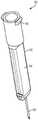
图2是联接到瓶和几何上对应的针组件的第一示例性瓶适配器的正视图,该瓶适配器以非使用位置示出;2 is a front view of a first exemplary vial adapter coupled to a vial and a geometrically corresponding needle assembly, the vial adapter shown in a non-use position;
图3是以使用位置示出的图2的瓶适配器和针组件的剖视图;Figure 3 is a cross-sectional view of the vial adapter and needle assembly of Figure 2 shown in a use position;
图4是图2的瓶适配器的正面正视图;Figure 4 is a front elevational view of the bottle adapter of Figure 2;
图5是图2的瓶适配器的左侧正视图;Figure 5 is a left side elevational view of the bottle adapter of Figure 2;
图6是图2的瓶适配器的右侧正视图;Figure 6 is a right side elevational view of the bottle adapter of Figure 2;
图7是图2的瓶适配器的顶部平面图;Figure 7 is a top plan view of the bottle adapter of Figure 2;
图8是图2的瓶适配器的俯视图;Figure 8 is a top view of the bottle adapter of Figure 2;
图9是图2的瓶适配器的分解透视图;Figure 9 is an exploded perspective view of the bottle adapter of Figure 2;
图10是图2的针组件的透视图;Figure 10 is a perspective view of the needle assembly of Figure 2;
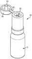
图11是联接到瓶和几何上对应的针组件的第二示例性瓶适配器的透视图,该瓶适配器以非使用位置示出;11 is a perspective view of a second exemplary vial adapter coupled to a vial and a geometrically corresponding needle assembly, the vial adapter shown in a non-use position;
图12是以使用位置示出的图11的瓶适配器和针组件的剖视图;Figure 12 is a cross-sectional view of the vial adapter and needle assembly of Figure 11 shown in a use position;
图13是联接到瓶的第三示例性瓶适配器的透视图;13 is a perspective view of a third exemplary bottle adapter coupled to a bottle;
图14是以使用位置示出的图13的瓶适配器和几何上对应的针组件的剖视图;14 is a cross-sectional view of the vial adapter and geometrically corresponding needle assembly of FIG. 13 shown in use position;
图15是联接到瓶的第四示例性瓶适配器的透视图;15 is a perspective view of a fourth exemplary bottle adapter coupled to a bottle;
图16是以清洁位置示出的第五示例性瓶适配器的透视图;16 is a perspective view of a fifth exemplary bottle adapter shown in a cleaning position;
图17是以抽取位置示出的图16的瓶适配器的透视图;Figure 17 is a perspective view of the bottle adapter of Figure 16 shown in an extraction position;
图18是以清洁位置示出的与图16的瓶适配器相似的另一瓶适配器的剖视图;Figure 18 is a cross-sectional view of another bottle adapter similar to the bottle adapter of Figure 16 shown in a cleaning position;
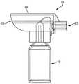
图19是以清洁位置示出的联接到瓶的第六示例性瓶适配器的正面正视图;19 is a front elevational view of a sixth exemplary bottle adapter coupled to a bottle shown in a clean position;
图20是以抽出位置示出的图19的瓶适配器的透视图;Figure 20 is a perspective view of the bottle adapter of Figure 19 shown in an extracted position;
图21是图20的瓶适配器的正面正视图;Figure 21 is a front elevational view of the bottle adapter of Figure 20;
图22是图21的瓶适配器的详细剖视图;Figure 22 is a detailed cross-sectional view of the bottle adapter of Figure 21;
图23是联接到瓶的第七示例性瓶适配器的透视图;23 is a perspective view of a seventh exemplary bottle adapter coupled to a bottle;
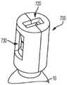
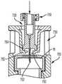
图24是图23的瓶适配器和几何上对应的针组件的剖视图,该瓶适配器以非使用位置示出;24 is a cross-sectional view of the vial adapter and geometrically corresponding needle assembly of FIG. 23, shown in a non-use position;
图25是以使用位置示出的图24的瓶适配器和针组件的剖视图;Figure 25 is a cross-sectional view of the vial adapter and needle assembly of Figure 24 shown in a use position;
图26是第八示例性瓶适配器的一半的透视图;26 is a perspective view of one half of an eighth exemplary bottle adapter;
图27是图26的瓶适配器的正视图;Figure 27 is a front view of the bottle adapter of Figure 26;
图28是图26的瓶适配器的用枢转件/铰接件联接在一起的两个半部的俯视图;以及Fig. 28 is a top view of the two halves of the bottle adapter of Fig. 26 coupled together with a pivot/hinge; and
图29是图26的瓶适配器的两个半部的透视图,其用枢转件/铰接件联接在一起。Figure 29 is a perspective view of the two halves of the bottle adapter of Figure 26 coupled together with pivots/hinges.
在多个视图中,相应的附图标记指示相应的部件。本文提出的示例说明了本发明的示例性实施例,并且这些示例不应被解释成以任何方式限制本发明的范围。Corresponding reference characters indicate corresponding parts throughout the several views. The examples presented herein illustrate exemplary embodiments of the invention, and these examples should not be construed to limit the scope of the invention in any way.
具体实施方式Detailed ways
首先参考图2-10,第一示例性瓶适配器100示出为与瓶10一起使用,并且几何上对应的针组件150示出为与注射器20(图1)或另一转移组件(例如,集成式胰岛素泵)一起使用。Referring first to FIGS. 2-10, a first
说明性的瓶适配器100包括基本上中空的主体101,该主体101具有大体上筒形且竖直的侧壁102以及大体上平坦且水平的上壁108。在图9所示的实施例中,侧壁102和上壁108是单独的部件,它们联接在一起以形成主体101,例如通过在侧壁102中设置窗口140,该窗口140接纳来自上壁108的相应的锁定突片142。侧壁102和上壁108一起整体地形成的方式也在本发明的范围内。主体101的侧壁102和/或上壁108可以是透明的,以允许瓶适配器100内部的可见性。主体101的侧壁102和/或上壁108也可以是颜色编码的或以其它方式标记,以在视觉上将瓶适配器100和相应的瓶10相关联。The
瓶适配器100具有延伸到瓶10上的下端104和在瓶10上方延伸的上端106。瓶适配器100还具有沿着轴线A在下端104和上端106之间测量的总高度H1,如图3所示。说明性的瓶适配器100的侧壁102基本上覆盖整个瓶10,因此,瓶适配器100的总高度H1超过瓶10自身的高度。例如,瓶适配器100的总高度H1可以从约70毫米(mm)至约80mm变化,例如约73mm。当然,该总高度H1可以变化,以适应不同尺寸的瓶10。侧壁102可以仅部分地覆盖瓶10的方案也在本公开的范围内。The
说明性的瓶适配器100包括环形联接组件110,其构造成将瓶适配器100联接到瓶10。瓶适配器100和瓶10之间的联接可以由瓶10的供应商执行,并且可以是永久性的,以减少最终使用者或其它中间方后来移除的可能性。联接组件110可以与瓶适配器100的侧壁102整体构成,或者联接组件110可以是固定地联接(例如,焊接、粘附、紧固)到瓶适配器100的侧壁102的单独部件。说明性的联接组件110包括第一组相对长且柔性的指部112和第二组相对短的U形且柔性的指部114,它们都从瓶适配器100的侧壁102朝向瓶10径向向内延伸。当瓶适配器100被向下按压到瓶10上时,各指部112被设计成围绕瓶10的凸缘12(包括图1的帽和周围的卷边密封件)径向向外折曲,然后向颈部14迅速返回或释放,这将瓶适配器100锁定在瓶10的凸缘12和卷边密封件下方的位置。同时,各指部114设计成压靠瓶10的肩部16。各压缩的指部114由此靠着朝向颈部14变窄的倾斜肩部16定位,以向瓶适配器100施加连续的向上的力,并且将指部112保持为靠在凸缘12的下侧。指部112、114的柔性可以允许联接组件110容纳不同形状和尺寸的瓶10。可选择地,指部114是刚性指部114,其抵靠肩部16,以对肩部16施加强制止动,从而向瓶适配器100施加连续的向上的力并且保持指部112靠在凸缘12的下侧。The
说明性的瓶适配器100还包括针端口或开口120,其延伸穿过上壁108,并且遵循沿着轴线A的线形路径。针开口120的入口121可以由联接(例如,焊接、粘附、紧固)到上壁108的单独的边缘122限定,或者针开口120的入口121可以直接由上壁108形成。在图9所示的实施例中,边缘122包括与上壁108的锥形轮廓匹配的锥形外表面124和一个或多个突起126,该突起126构造成卡入上壁108中相应的凹槽128中。还可以设置可选的帽或盖(未示出),以选择性地覆盖针开口120的入口121。The
针开口120的尺寸和形状确定成容纳针组件150的几何上对应的针座153(如下面进一步讨论的那样),但不是传统的或常用注射器的针座(例如,图1的注射器20的标准针座23)。例如,针开口120的尺寸和形状可以确定成容纳与U-200胰岛素相关联的针组件150,而不是通常与U-100胰岛素瓶一起使用的标准注射器20。结果,针开口120可以降低使用与U-100胰岛素相关联的标准注射器20从瓶10中抽取不适当或非预期的药物(在该示例中是U-200胰岛素)的可能性。因为标准注射器20的针座23的形状通常是圆形,所以针开口120的尺寸可以确定成小于注射器20的针座23和/或可以是键槽式或非圆形的形状,以防止注射器20的针座23插入。在图7所示的实施例中,针开口120是具有圆角的矩形形状,但是针开口120是椭圆形、三角形、十字形、星形或其它合适的不与标准针座23适配的形状也在本公开的范围内。此外,在装配时,瓶适配器100的针开口120与瓶10的塞子18隔开足够的高度H2(该高度H2小于瓶适配器100的总高度H1),以在针座23抵接瓶适配器100的上壁108或边缘122时,防止标准注射器20(图1)的针22到达瓶10的塞子18。换句话说,针开口120和塞子18之间的高度H2可能超过标准注射器20的针22的长度L(图1)。例如,高度H2可以从约15mm到约25mm变化,例如约20mm。可以根据特定注射器20或其它需要防止进入的标准传送组件的尺寸和形状来调节针开口120的尺寸和形状以及瓶适配器100的高度H2。The
示例性瓶适配器100还包括清洁通道130,其至少部分地被罩盖132包围。清洁通道130的入口131图示成延伸穿过主体101的侧壁102,但是该位置可以改变。罩盖132图示成作为主体101的上壁108的连续延伸部从轴线A径向向外延伸,但是该位置也可以改变。在图3所示的实施例中,侧壁102从下端104径向向外偏离到上端106,以跟随罩盖132的路径。结果,由侧壁102限定的清洁通道130的入口131也从入口131的下端136径向向外延伸到入口131的上端138。清洁通道130的入口131还可以包括凹口139,以便于使用者访问/进入。在图3所示的实施例中,凹口139定位成比入口131的上端138更靠近入口131的下端136。在所示实施例中,下端136径向向外弯曲,以便于到达/访问/接近瓶的帽19(图1),使得使用者可以用使用者的手指或工具移除该帽。例如,图3所示的下端136和塞子18之间的加宽空间可以允许使用者插入手指或工具,以向帽19的悬伸部分施加向上的力,以在使用之前将帽19从瓶10上弹开。在其它实施例中,下端136与侧壁102齐平。The
清洁通道130与瓶适配器100的针开口120不同。清洁通道130的尺寸和形状确定成允许与使用者的手指一起的含有消毒剂(例如,酒精)的清洁装置(例如,垫、湿巾、棉签)(如果需要的话)在使用前到达/接近并清洁瓶10的塞子18。如上所述,清洁通道130还可以用于在使用前从瓶10的塞子18上移除任何密封件或盖子。清洁通道130的入口131示例性地大于针开口120的入口121,以在需要时容纳这种清洁装置和使用者的手指。The cleaning
在所示实施例中,与针开口120不同,清洁通道130不旨在允许针到达/进入塞子18,例如注射器20的针(图1)、针组件150(图2)的针或另一种药物转移组件的针。因此,清洁通道130和/或罩盖132的尺寸和形状确定成阻止针不期望地经由通道130插入通过塞子18。因此,针开口120提供针到达塞子18的途径,而罩盖132阻止针通过通道130到达塞子18。罩盖132可以从轴线A突出距离D(图3),该距离D是约20mm至约30mm,例如约27mm。结果,通过清洁通道130到达/接近瓶10的塞子18可以在第一角度α1和第二角度α2之间偏离轴线A,该第一角度α1通过入口131的上端138测量,该第二角度α2通过入口131的下端136测量。第一角度α1可以大于约50度,更具体地约50度至约80度,甚至更具体地约60度至约70度。第二角度α2可以小于约150度,更具体地约90度至约150度,甚至更具体地约110度至约120度。可以根据具体注射器20、针或其它需要防止达到/访问的传送组件的尺寸和形状来调节清洁通道130和/或罩盖132的尺寸和形状。清洁通道130遵循非线形路径来进一步阻止针经由通道130插入穿过塞子18也在本公开的范围内。In the illustrated embodiment, unlike the
说明性的针组件150具有针座153和联接到针座153的针/插管152。针座153具有键槽式外部轮廓154,其特别地与几何上对应的瓶适配器100中的针开口120的形状相匹配。因为说明性的瓶适配器100中的针开口120是矩形的,相应的针座153的外部轮廓154也是矩形的,但是可以提供其它形状,如上所述。针组件150可以可拆卸地联接到图1的注射器20(在标准针座23移除的情况下)或另一标准传送组件。在一个实施例中,注射器20具有承插式

在使用中,针组件150联接到注射器(例如,图1的移除了针座23的注射器20)或其它转移装置。如果需要,通过清洁通道130移除瓶10的帽19(图1),并用消毒剂清洁塞子18。然后,以键槽的方式将针组件150插入相应的瓶适配器100的针开口120中,如图3所示。在该位置,针组件150的针152能够沿着轴线A到达并刺穿瓶10的塞子18,以从瓶10抽出预期的药物,在该示例中是U-200胰岛素。最后,将抽出的药物转移到输送装置(未示出),例如胰岛素泵,或者直接输送到患者。输送装置可以包括键槽式接口,其与针座153的外部轮廓相匹配,以将胰岛素接纳到装置的储器中。In use,
可以为瓶10(图1)中的每种可获得的药物浓度或至少为较高的药物浓度提供一组不同的瓶适配器100和相应的针组件150。瓶适配器100中的针开口120的形状和相应的针组件150的外部轮廓154可以对于每种浓度各不相同。如果图2-10所示的矩形开口120和针组件150例如设置成与包含U-200胰岛素的瓶10一起使用,则可以设置不同形状的针开口120和针组件150以和包含U-500胰岛素的瓶10一起使用。为了便于制造,不同的瓶适配器100的尺寸和形状可以基本相同,除了提供形成不同形状的针开口120的不同边缘122之外。对于不同的胰岛素浓度,瓶适配器100的高度H2也可以不同。A different set of
然后参考图11和图12,示出了与瓶10一起使用的第二示例性瓶适配器200和针组件250。瓶适配器200和针组件250与上述瓶适配器100和针组件150相似,除了如下所述的之外,其中相似的附图标记标识相似的元件。说明性的瓶适配器200的侧壁202仅延伸到瓶10的肩部16,而不是基本上覆盖整个瓶10,如图2所示。在该实施例中,在缩短的下端204和上端206之间测量的瓶适配器200的总高度H1可以从约30mm至约40mm变化,例如约34mm。瓶适配器200的总高度H1可以小于瓶10的高度。说明性的瓶适配器200包括遵循线形路径到瓶10的针开口220和遵循非线形路径到瓶10的清洁通道230。Referring then to Figures 11 and 12, a second
然后参考图13和14,示出了与瓶10一起使用的第三示例性瓶适配器300和针组件350。瓶适配器300和针组件350与上述瓶适配器100、200和针组件150、250相似,相似的附图标记标识相似的元件,除了如下所述之外。说明性的瓶适配器300包括盖或帽360,其构造成选择性地覆盖针开口320。帽360包括联接到瓶适配器300的主体301的柔性枢转件/铰接件/铰链362和插塞364,该插塞364的尺寸确定成容纳在瓶适配器300的针开口320中。插塞364的尺寸可以确定成当帽360关闭时插塞364接触瓶10的塞子18,以防止异物到达塞子18。塞子364还可以在其表面上包括抗微生物材料,以在帽360关闭时清洁瓶10的塞子18。说明性的瓶适配器300没有了不同于针开口320清洁通道,因此,可以使用针开口320来清洁瓶10和从瓶10抽取药物。因此,当帽360打开时,如图13所示,瓶10的塞子18可以通过针开口320暴露,以用于清洁和抽取药物。Referring then to Figures 13 and 14, a third
然后参考图15,示出了与瓶10一起使用的第四示例性瓶适配器400。瓶适配器400与上述瓶适配器300相似,除了如下所述之外,其中相似的附图标记标识相似的元件。示例性的瓶适配器400在侧壁402中包括与针开口420不同的清洁通道430。清洁通道430的尺寸和形状确定成允许含有消毒剂(例如,酒精)的清洁装置(例如,垫、湿巾、棉签)与使用者的手指(以虚线示出)一起在使用之前到达并清洁瓶10的塞子18。Referring then to FIG. 15 , a fourth
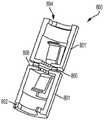
然后参考图16-18,示出了与瓶10一起使用的第五示例性瓶适配器500。瓶适配器500与上述瓶适配器100-400相似,除了如下所述之外,其中相似的附图标记标识相似的元件。瓶适配器500包括外部主体501、针开口520和不同的清洁通道530。另外,瓶适配器500包括内部主体570,其在如图16和18所示的清洁位置与如图17所示的抽取位置之间可旋转地布置在外部主体501中。在图16的清洁位置,内部主体570通过将针开口520的形状变窄和/或改变,以至少部分地阻挡进入针开口520,同时允许进入清洁通道530。在图18的清洁位置,内部主体570完全阻挡针开口520,同时允许进入清洁通道530。在图17的抽取位置,内部主体570旋转到暴露针开口520并阻挡进入清洁通道530。通过区分清洁过程和抽取过程,瓶适配器500可以降低在清洁过程中无意针刺伤害使用者的风险。Referring then to FIGS. 16-18 , a fifth
然后参考图19-22,示出了与瓶10一起使用的第六示例性瓶适配器600。瓶适配器600与上述瓶适配器100-500相似,除了如下所述之外,相似的附图标记标识相似的元件。瓶适配器600包括可枢转的盖子680,其在一端限定针开口620,在另一端限定清洁通道630。盖子680可以在图19所示的清洁位置与图20和21所示的抽取位置之间旋转。在图19的清洁位置,盖子680旋转到大体上水平的位置。在该清洁位置,使用者可以通过大体上水平的清洁通道630用清洁装置到达/接近瓶10的塞子18(图20),但是不能用针通过大体上水平的针开口620到达/接近瓶10的塞子18。在图20和21的抽取位置,盖子680旋转到大体上竖直的位置。在该抽取位置,使用者可以用针通过大体上竖直的针开口620到达/接近瓶10的塞子18,但是不能用清洁装置通过关闭的且大体上竖直的清洁通道630到达瓶10的塞子18。如图22所示,也可以在盖子680中设置一个或多个阻挡构件682,以在抽取位置进一步保护瓶10的塞子18,直到如上所述的几何上对应的针组件(未示出)进入针开口620并且使阻挡构件682移开(例如,枢转)。同样,通过区分清洁过程和抽取过程,瓶适配器600可以降低在清洁过程中无意针刺伤害使用者的风险。Referring then to FIGS. 19-22 , a sixth
使用与上述联接组件110(图3)相似的联接组件610将瓶适配器600联接到瓶10。图22的说明性的联接组件610位于瓶适配器600的下端604处或附近,并且包括第一组相对短且柔性的指部612和第二组相对长且柔性的指部614,它们都从瓶适配器600的侧壁602朝向瓶10径向向内延伸。当瓶适配器600被向下压到瓶10上时,各指部612设计成围绕瓶10的凸缘12折曲,然后向颈部14迅速返回或释放,这将瓶适配器600锁定在瓶10的凸缘12下方的位置。同时,各指部614设计成在肩部16之上折曲,同时抵接边缘12。各折曲的指部614可通过沿着朝向颈部14变窄的倾斜肩部16尽可能向上移动而试图释放,这可以向瓶适配器100施加连续的向上的力,并且使指部612与边缘12保持接触。指部612、614的柔性可以允许联接组件610容纳不同形状和尺寸的瓶10。The
然后参考图23-25,示出了与瓶10一起使用的第七示例性瓶适配器700和针组件750。瓶适配器700和针组件750与上述瓶适配器100-600和针组件150-350相似,除了如下所述之外,其中相似的附图标记标识相似的元件。说明性的瓶适配器700包括一个或多个内部阻挡构件782。说明性的针组件750包括针752和一个或多个相应的凸缘784。在如图24所示的非使用位置,阻挡构件782被偏压在一起,以保护瓶10的塞子18。在如图25所示的抽取位置,几何上对应的针组件750进入针开口720,并且凸缘784将阻挡构件782移动分开,以使瓶10的塞子18向针752暴露。为了清洁瓶10,含有消毒剂的清洁装置可以通过瓶适配器700的不同的清洁通道730插入,如上面进一步所述的那样。可选择地,可以设置模仿针组件750的尺寸和形状的含有消毒剂的清洁装置,以插入阻挡构件782之间,使得清洁装置代替针752。Referring then to Figures 23-25, a seventh
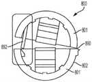
然后参考图26-29,示出了与瓶10一起使用的第八示例性瓶适配器800。瓶适配器800与上述瓶适配器100-700相似,除了如下所述的之外,其中相似的附图标记标识相似的元件。说明性的瓶适配器800包括由主体件801、801'制成的两件式主体。在一侧,主体件801、801'可以使用柔性枢转件/铰接件890联接在一起。在图28所示的实施例中,枢转件/铰接件890沿着瓶适配器800的侧壁802定位。在图29所示的实施例中,枢转件/铰接件890沿着瓶适配器800的上壁808定位。在另一侧,主体件801、801'可以使用一个或更多个紧固件联接在一起,例如主体件801上的钉892,该钉892接纳在另一主体件801'中的凹部894中。围绕瓶10将主体件801、801'焊接、粘附或以其它方式联接在一起也在本公开的范围内。可以设置垫圈896,其在凸缘12和肩部16之间适配在瓶10的颈部14中,以将瓶适配器800密封到瓶10上,如图27所示。Referring then to FIGS. 26-29 , an eighth
可以将上述瓶适配器100-800的各种特征组合和匹配。例如,图2-9的瓶适配器100可以包括与图11和12的侧壁202相似的局部长度的侧壁、与图13和14的帽360相似的帽、与图22的联接组件610相似的联接组件、与图24-25的阻挡构件782相似的一个或更多个阻挡构件、和/或与图27的垫圈896相似的垫圈。The various features of the bottle adapters 100-800 described above can be combined and matched. For example, the
尽管本发明已经描述成具有示例性设计,但是在本公开的精神和范围内,还可以修改本发明。因此,本申请旨在涵盖本发明的使用其一般原理的任何变化、用途或修改。此外,本申请旨在覆盖如下背离本发明的方案,只要这些方案属于本发明所属领域的已知或惯常实践,并且落入随附权利要求的限制内。While this invention has been described as having an exemplary design, the present invention can be further modified within the spirit and scope of this disclosure. Accordingly, this application is intended to cover any variations, uses, or adaptations of the invention using its general principles. Furthermore, this application is intended to cover such departures from the invention as come within known or customary practice in the art to which this invention pertains and which fall within the limits of the appended claims.
Claims (18)
Applications Claiming Priority (3)
| Application Number | Priority Date | Filing Date | Title |
|---|---|---|---|
| US201662377853P | 2016-08-22 | 2016-08-22 | |
| US62/377,853 | 2016-08-22 | ||
| PCT/US2017/047563WO2018039065A1 (en) | 2016-08-22 | 2017-08-18 | Secured medication transfer system |
Publications (2)
| Publication Number | Publication Date |
|---|---|
| CN109640920A CN109640920A (en) | 2019-04-16 |
| CN109640920Btrue CN109640920B (en) | 2022-06-07 |
Family
ID=59714180
Family Applications (1)
| Application Number | Title | Priority Date | Filing Date |
|---|---|---|---|
| CN201780051252.9AActiveCN109640920B (en) | 2016-08-22 | 2017-08-18 | Safe drug transfer system |
Country Status (8)
| Country | Link |
|---|---|
| US (2) | US11730678B2 (en) |
| EP (1) | EP3500226B1 (en) |
| JP (1) | JP6715384B2 (en) |
| CN (1) | CN109640920B (en) |
| AU (1) | AU2017317170B2 (en) |
| CA (1) | CA3033377C (en) |
| ES (1) | ES2809374T3 (en) |
| WO (1) | WO2018039065A1 (en) |
Families Citing this family (2)
| Publication number | Priority date | Publication date | Assignee | Title |
|---|---|---|---|---|
| CN109640920B (en) | 2016-08-22 | 2022-06-07 | 伊莱利利公司 | Safe drug transfer system |
| USD907193S1 (en)* | 2018-02-21 | 2021-01-05 | Eli Lilly And Company | Secured medication transfer set |
Family Cites Families (131)
| Publication number | Priority date | Publication date | Assignee | Title |
|---|---|---|---|---|
| GB325959A (en) | 1929-01-25 | 1930-03-06 | Joseph Vincent Coogan | Improved means for the charging of disinfectant, anaesthetic and like syringes |
| US4150673A (en) | 1977-02-03 | 1979-04-24 | Pharmachem Corporation | Coded entry system for blood bag |
| US4619640A (en) | 1984-08-17 | 1986-10-28 | Potolsky Abraham I | Blood transfusion connector assembly |
| US5017186A (en)* | 1989-07-11 | 1991-05-21 | Arnold Victor A | Device and method for maintaining sterility of multi-dose medicament vials |
| AU657596B2 (en) | 1992-01-31 | 1995-03-16 | Becton Dickinson & Company | Surgical dilator |
| US5700244A (en) | 1992-04-17 | 1997-12-23 | Science Incorporated | Fluid dispenser with fill adapter |
| US6086560A (en) | 1992-04-17 | 2000-07-11 | Science Incorporated | Fluid dispenser with fill adapter |
| US5429256A (en)* | 1994-01-24 | 1995-07-04 | Kestenbaum; Alan D. | Drug withdrawal system for container |
| US5832971A (en) | 1994-05-19 | 1998-11-10 | Becton, Dickinson And Company | Syringe filling and delivery device |
| US5620427A (en) | 1995-04-27 | 1997-04-15 | David R. Kipp | Luer lock system |
| US6086561A (en) | 1995-05-01 | 2000-07-11 | Science Incorporated | Fluid delivery apparatus with reservoir fill assembly |
| US6293159B1 (en) | 1995-05-01 | 2001-09-25 | Science Incorporated | Fluid delivery apparatus with reservoir fill assembly |
| US5725511A (en) | 1995-09-07 | 1998-03-10 | Urrutia; Sharon A. | Method and apparatus for prevention of blood-type mismatches |
| US5957891A (en) | 1995-10-11 | 1999-09-28 | Science Incorporated | Fluid delivery device with fill adapter |
| US6277095B1 (en) | 1995-10-11 | 2001-08-21 | Science Incorporated | Fluid delivery device with full adapter |
| US5776103A (en) | 1995-10-11 | 1998-07-07 | Science Incorporated | Fluid delivery device with bolus injection site |
| US5807335A (en) | 1995-12-22 | 1998-09-15 | Science Incorporated | Fluid delivery device with conformable ullage and fill assembly |
| US5807355A (en) | 1996-12-09 | 1998-09-15 | Advanced Cardiovascular Systems, Inc. | Catheter with rapid exchange and OTW operative modes |
| US6355019B1 (en) | 1996-12-18 | 2002-03-12 | Science Incorporated | Variable rate infusion apparatus with indicator and adjustable rate control |
| US6402207B1 (en) | 1997-06-09 | 2002-06-11 | Qd Enterprises, Llc | Safety indexed medical connectors |
| US6132416A (en) | 1998-09-01 | 2000-10-17 | Broselow; James B. | Universal medication dosing system |
| US6022339A (en) | 1998-09-15 | 2000-02-08 | Baxter International Inc. | Sliding reconstitution device for a diluent container |
| EP1033143B1 (en) | 1999-02-26 | 2007-01-10 | F. Hoffmann-La Roche Ag | Device for administering a medication |
| US6453956B2 (en) | 1999-11-05 | 2002-09-24 | Medtronic Minimed, Inc. | Needle safe transfer guard |
| US6253804B1 (en) | 1999-11-05 | 2001-07-03 | Minimed Inc. | Needle safe transfer guard |
| EP1381408A4 (en) | 2001-02-22 | 2007-06-13 | Insulet Corp | Modular infusion device and method |
| US6890310B2 (en) | 2001-03-30 | 2005-05-10 | Becton, Dickinson And Company | Adaptor for use with point-of-care testing cartridge |
| US8034026B2 (en) | 2001-05-18 | 2011-10-11 | Deka Products Limited Partnership | Infusion pump assembly |
| US6500153B1 (en) | 2001-07-13 | 2002-12-31 | Children's And Women's Health Centre Of British Columbia | Syringe and needle for preventing inadvertent drug injection |
| USD462761S1 (en) | 2001-08-07 | 2002-09-10 | Becton Dickinson And Company | Transfer device |
| USD460551S1 (en) | 2001-08-07 | 2002-07-16 | Becton, Dickinson And Company | Transfer device |
| USD460181S1 (en) | 2001-08-07 | 2002-07-09 | Becton, Dickinson And Company | Transfer device |
| ATE333260T1 (en) | 2001-08-27 | 2006-08-15 | Novo Nordisk As | A CARTRIDGE AND A MEDICAL DELIVERY SYSTEM THAT ACCOMMODATE SUCH A CARTRIDGE |
| US20030105428A1 (en) | 2001-12-05 | 2003-06-05 | John Hogan | Electronically controlled fluid delivery device |
| US6874522B2 (en) | 2002-06-18 | 2005-04-05 | Baxter International Inc. | Luer-actuated solution path connector with membrane and container using the connector and a method for establishing fluid communication with the container |
| US20060047251A1 (en) | 2002-10-22 | 2006-03-02 | Philip Bickford Smith | Medical small-bore tubing system and kit |
| IN2014MN00187A (en) | 2003-10-30 | 2015-08-21 | Teva Medical Ltd | |
| US7615041B2 (en) | 2004-07-29 | 2009-11-10 | Boston Scientific Scimed, Inc. | Vial adaptor |
| JP4319601B2 (en) | 2004-08-26 | 2009-08-26 | 川澄化学工業株式会社 | Curved needle with wings |
| ES2827179T3 (en) | 2004-09-10 | 2021-05-20 | Becton Dickinson Co | Infusion reconstitution device |
| US7731678B2 (en)* | 2004-10-13 | 2010-06-08 | Hyprotek, Inc. | Syringe devices and methods for mixing and administering medication |
| US20060235364A1 (en) | 2005-04-13 | 2006-10-19 | Wizard Med, Llc | Needle-less fluid delivery assembly and error prevention system |
| US8070739B2 (en)* | 2005-08-11 | 2011-12-06 | Medimop Medical Projects Ltd. | Liquid drug transfer devices for failsafe correct snap fitting onto medicinal vials |
| US20070179454A1 (en) | 2006-01-31 | 2007-08-02 | Smiths Medical Asd, Inc. | Safety needle assembly with correct medication connection |
| US10010669B2 (en) | 2006-02-09 | 2018-07-03 | Deka Products Limited Partnership | Systems and methods for fluid delivery |
| EP3165247B1 (en) | 2006-02-09 | 2020-10-28 | DEKA Products Limited Partnership | Pumping fluid delivery systems and methods using force application assembley |
| US9839743B2 (en) | 2006-02-09 | 2017-12-12 | Deka Products Limited Partnership | Apparatus, system and method for fluid delivery |
| CN2882607Y (en) | 2006-03-03 | 2007-03-28 | 陈庆昌 | Puzzle lock able to identify bottled medicaments |
| CN101028226A (en) | 2006-03-03 | 2007-09-05 | 陈庆昌 | Code lock for discriminating bottled medicament |
| TWM294327U (en) | 2006-03-08 | 2006-07-21 | Ching-Chang Chen | Medicine secret code lock |
| US7547300B2 (en) | 2006-04-12 | 2009-06-16 | Icu Medical, Inc. | Vial adaptor for regulating pressure |
| EP2037987B1 (en) | 2006-06-30 | 2019-09-04 | Novo Nordisk A/S | A medical delivery system comprising a coding mechanism |
| GB2446778A (en) | 2007-02-01 | 2008-08-27 | Pa Knowledge Ltd | Syringe adaptor |
| KR101507841B1 (en) | 2007-04-23 | 2015-04-07 | 플라스트메드 리미티드 | Method and apparatus for contamination-free transfer of a hazardous drug |
| US8323250B2 (en) | 2007-04-30 | 2012-12-04 | Medtronic Minimed, Inc. | Adhesive patch systems and methods |
| US20080306439A1 (en) | 2007-06-08 | 2008-12-11 | Nelson M Bud | Devices for mixing and applying a fluid composition |
| US8029747B2 (en)* | 2007-06-13 | 2011-10-04 | Carmel Pharma Ab | Pressure equalizing device, receptacle and method |
| US8216207B2 (en) | 2007-08-01 | 2012-07-10 | Hospira, Inc. | Medicament admixing system |
| WO2009026443A2 (en) | 2007-08-21 | 2009-02-26 | Gilero, Llc | Vial access and injection system |
| BRPI0817907B8 (en) | 2007-10-02 | 2021-06-22 | Lamodel Ltd | apparatus for administering a substance to an individual |
| US20090099552A1 (en) | 2007-10-12 | 2009-04-16 | Maureen Levy | Drug delivery route-based connector system and method |
| WO2009060419A2 (en) | 2007-11-08 | 2009-05-14 | Elcam Medical A.C.A..L. Ltd | Vial adaptor and manufacturing method therfor |
| US7918825B2 (en) | 2007-11-29 | 2011-04-05 | Insulet Corporation | Interfacing a prefilled syringe with an infusion pump to fill the infusion pump |
| US7806868B2 (en) | 2007-11-30 | 2010-10-05 | Roche Diagnostics Operations, Inc. | Drug reservoir loading and unloading mechanism for a drug delivery device using a unidirectional rotated shaft |
| US8881774B2 (en) | 2007-12-31 | 2014-11-11 | Deka Research & Development Corp. | Apparatus, system and method for fluid delivery |
| US10080704B2 (en) | 2007-12-31 | 2018-09-25 | Deka Products Limited Partnership | Apparatus, system and method for fluid delivery |
| CA2720233A1 (en) | 2008-04-01 | 2009-12-03 | Yukon Medical, Llc | Dual container fluid transfer device |
| US8728024B2 (en) | 2008-10-10 | 2014-05-20 | Deka Products Limited Partnership | Infusion pump methods, systems and apparatus |
| US9833569B2 (en) | 2008-10-10 | 2017-12-05 | Deka Products Limited Partnership | Infusion pump assembly |
| WO2010053570A1 (en) | 2008-11-07 | 2010-05-14 | Becton, Dickinson And Company | Syringe housing to facilitate medication injection |
| EP2355770A1 (en) | 2008-11-12 | 2011-08-17 | British Columbia Cancer Agency Branch | Vial handling and injection safety systems and connectors |
| WO2010078207A1 (en) | 2008-12-31 | 2010-07-08 | Deka Products Limited Partnership | Split ring resonator antenna adapted for use in wirelessly controlled medical device |
| US8512309B2 (en) | 2009-01-15 | 2013-08-20 | Teva Medical Ltd. | Vial adapter element |
| WO2010099000A2 (en) | 2009-02-24 | 2010-09-02 | Teva Medical Ltd. | Vial adapter assembly in drug mixing system |
| WO2010120953A2 (en) | 2009-04-14 | 2010-10-21 | Yukon Medical, Llc | Fluid transfer device |
| EP2432527B1 (en) | 2009-05-20 | 2019-10-02 | Sanofi-Aventis Deutschland GmbH | A system comprising a drug delivery device and a cartridge provided with a bung and a method of identifying the cartridge |
| US9242042B2 (en) | 2009-07-21 | 2016-01-26 | Ethicon Endo-Surgery, Inc. | Drug delivery system including a drug-container holder and a pump assembly |
| US8356644B2 (en) | 2009-08-07 | 2013-01-22 | Medtronic Minimed, Inc. | Transfer guard systems and methods |
| US8449504B2 (en) | 2009-11-11 | 2013-05-28 | Calibra Medical, Inc. | Wearable infusion device and system |
| IL202069A0 (en) | 2009-11-12 | 2010-06-16 | Medimop Medical Projects Ltd | Fluid transfer device with sealing arrangement |
| CN103585015B (en)* | 2009-12-04 | 2016-03-23 | 泰尔茂株式会社 | Vial adapter |
| SG183104A1 (en) | 2010-01-15 | 2012-09-27 | Bayer Healthcare Llc | Device |
| JP2013517081A (en) | 2010-01-19 | 2013-05-16 | ケンブリッジ・エンタープライズ・リミテッド | Apparatus and method |
| DK2512399T3 (en) | 2010-02-24 | 2015-06-22 | Medimop Medical Projects Ltd | Fluid transfer device with vent arrangement |
| ES2655593T3 (en) | 2010-04-09 | 2018-02-20 | Sanofi-Aventis Deutschland Gmbh | Coded element for connecting drug reservoir with articulated flange |
| WO2011131779A1 (en) | 2010-04-23 | 2011-10-27 | Sanofi-Aventis Deutschland Gmbh | Drug delivery device and drug reservoir with mechanical coding mechanism |
| US8968257B2 (en) | 2010-04-23 | 2015-03-03 | Sanofi-Aventis Deutschland Gmbh | Coded cartridge holder system for a fluid delivery device |
| MX348044B (en) | 2010-05-27 | 2017-05-25 | J&J Solutions Inc | Closed fluid transfer system. |
| US20120000569A1 (en) | 2010-07-01 | 2012-01-05 | Wiegel Christopher D | Reservoir filling aid for a medical pump |
| WO2012010564A1 (en) | 2010-07-19 | 2012-01-26 | Sanofi-Aventis Deutschland Gmbh | Medicament cartridges with non-standard dimensions |
| US8465461B2 (en) | 2010-07-27 | 2013-06-18 | Becton, Dickinson And Company | Blunt needle safety drug delivery system |
| US9675751B2 (en) | 2010-07-31 | 2017-06-13 | Becton, Dickinson And Company | Infusion reservoir with push-on connector features and/or attachments therefor |
| BR112013001708A2 (en) | 2010-08-10 | 2016-05-31 | Hoffmann La Roche | device and method for automatically reconstituting a drug |
| WO2012019641A1 (en) | 2010-08-10 | 2012-02-16 | F. Hoffmann-La Roche Ag | Drug reconstitution and delivery device |
| JP2013533078A (en) | 2010-08-13 | 2013-08-22 | サノフィ−アベンティス・ドイチュラント・ゲゼルシャフト・ミット・ベシュレンクテル・ハフツング | Identification for drug delivery devices |
| US9814870B2 (en) | 2010-08-17 | 2017-11-14 | Becton, Dickinson And Company | Non-luer connectors |
| EP2605815B1 (en) | 2010-08-19 | 2019-12-25 | Sanofi-Aventis Deutschland GmbH | Method and system for determining information related to a drug reservoir using an electronic sensor |
| NZ606732A (en) | 2010-08-25 | 2015-01-30 | Baxter Healthcare Sa | Assembly to facilitate user reconstitution |
| USD720067S1 (en) | 2011-05-02 | 2014-12-23 | Carmel Pharma Ab | Medical device |
| US8870238B2 (en) | 2011-06-27 | 2014-10-28 | Smiths Medical Asd, Inc. | Fitting for medicament infusion systems |
| US9220833B2 (en) | 2011-06-27 | 2015-12-29 | Smiths Medical Asd, Inc. | Medicament infusion systems |
| US9861383B2 (en) | 2011-08-31 | 2018-01-09 | Smiths Medical Asd, Inc. | Needle assembly |
| US9402782B2 (en) | 2011-12-15 | 2016-08-02 | Ge Healthcare As | Package with tamper-evident features |
| SG11201404436XA (en)* | 2012-02-02 | 2014-08-28 | Becton Dickinson Holdings Pte Ltd | Adaptor for coupling with a medical container |
| USD720451S1 (en) | 2012-02-13 | 2014-12-30 | Medimop Medical Projects Ltd. | Liquid drug transfer assembly |
| US11524151B2 (en) | 2012-03-07 | 2022-12-13 | Deka Products Limited Partnership | Apparatus, system and method for fluid delivery |
| JP6267185B2 (en)* | 2012-04-09 | 2018-01-24 | ベクトン・ディキンソン・アンド・カンパニーBecton, Dickinson And Company | Drug vial safety device |
| US9180242B2 (en) | 2012-05-17 | 2015-11-10 | Tandem Diabetes Care, Inc. | Methods and devices for multiple fluid transfer |
| CA2878847C (en)* | 2012-07-12 | 2018-05-01 | Antares Pharma, Inc. | Liquid-transfer adapter beveled spike |
| JP2016500013A (en) | 2012-10-16 | 2016-01-07 | スイスイノヴ プロダクト サールSwissinnov Product Sarl | Fluid supply system and method |
| SG11201501947RA (en) | 2012-12-17 | 2015-04-29 | Unitract Syringe Pty Ltd | Vial adapters |
| EP3178520B1 (en) | 2013-03-08 | 2018-12-12 | Becton, Dickinson and Company | Syringe-iv access locking device |
| US20160000653A1 (en) | 2013-03-14 | 2016-01-07 | Bayer Healthcare Llc | Transfer set |
| US9597260B2 (en) | 2013-03-15 | 2017-03-21 | Becton Dickinson and Company Ltd. | System for closed transfer of fluids |
| IL225734A0 (en) | 2013-04-14 | 2013-09-30 | Medimop Medical Projects Ltd | Ready-to-use drug vial assemblages including drug vial and drug vial closure having fluid transfer member, and drug vial closure therefor |
| IL226281A (en) | 2013-05-09 | 2017-01-31 | Kriheli Marino | Needle valve and connectors for use in liquid transfer apparatuses |
| US9617020B2 (en) | 2013-07-03 | 2017-04-11 | Deka Products Limited Partnership | Apparatus, system and method for fluid delivery |
| MX376285B (en) | 2013-07-03 | 2025-03-07 | Deka Products Lp | FLUID CONNECTOR ASSEMBLY. |
| WO2015017858A1 (en) | 2013-08-02 | 2015-02-05 | J&J SOLUTIONS, INC. d.b.a CORVIDA MEDICAL | Compounding systems and methods for safe medicament transport |
| CA2929476C (en) | 2013-11-06 | 2019-01-22 | Becton Dickinson and Company Limited | System for closed transfer of fluids with a locking member |
| USD747472S1 (en) | 2014-01-06 | 2016-01-12 | Zoetis Services Llc | Fluid transfer device |
| DE102014104281B3 (en) | 2014-03-27 | 2015-09-10 | Medac Gesellschaft für klinische Spezialpräparate mbH | transfer device |
| EP3134058B1 (en) | 2014-04-21 | 2020-03-18 | Becton Dickinson and Company Limited | Fluid transfer device and packaging therefor |
| EP3145561A1 (en) | 2014-05-20 | 2017-03-29 | Cequr SA | Medicine delivery device with restricted access filling port |
| WO2016004329A1 (en) | 2014-07-03 | 2016-01-07 | Deka Products Limited Partnership | Infusion pump assembly |
| JP6358724B2 (en) | 2015-01-05 | 2018-07-18 | ウエスト・ファーマ.サービシーズ・イスラエル,リミテッド | Dual vial adapter assembly with easy removable pill adapter to ensure accurate use |
| USD801522S1 (en) | 2015-11-09 | 2017-10-31 | Medimop Medical Projects Ltd. | Fluid transfer assembly |
| WO2017120251A1 (en) | 2016-01-04 | 2017-07-13 | Insulet Corporation | Filling assist mechanisms and keyed interfaces for drug delivery devices |
| CN109640920B (en) | 2016-08-22 | 2022-06-07 | 伊莱利利公司 | Safe drug transfer system |
| USD832430S1 (en) | 2016-11-15 | 2018-10-30 | West Pharma. Services IL, Ltd. | Dual vial adapter assemblage |
| US11224555B2 (en) | 2018-04-23 | 2022-01-18 | Hospira, Inc. | Access and vapor containment system for a drug vial and method of making and using same |
- 2017
- 2017-08-18CNCN201780051252.9Apatent/CN109640920B/enactiveActive
- 2017-08-18JPJP2019502087Apatent/JP6715384B2/enactiveActive
- 2017-08-18AUAU2017317170Apatent/AU2017317170B2/enactiveActive
- 2017-08-18USUS16/323,650patent/US11730678B2/enactiveActive
- 2017-08-18CACA3033377Apatent/CA3033377C/enactiveActive
- 2017-08-18ESES17758402Tpatent/ES2809374T3/enactiveActive
- 2017-08-18WOPCT/US2017/047563patent/WO2018039065A1/ennot_activeCeased
- 2017-08-18EPEP17758402.6Apatent/EP3500226B1/enactiveActive
- 2023
- 2023-08-02USUS18/363,981patent/US12336966B2/enactiveActive
Also Published As
| Publication number | Publication date |
|---|---|
| EP3500226B1 (en) | 2020-06-03 |
| US20230372198A1 (en) | 2023-11-23 |
| JP6715384B2 (en) | 2020-07-01 |
| AU2017317170A1 (en) | 2019-01-24 |
| EP3500226A1 (en) | 2019-06-26 |
| CA3033377C (en) | 2021-01-12 |
| JP2019520939A (en) | 2019-07-25 |
| US20190167526A1 (en) | 2019-06-06 |
| US11730678B2 (en) | 2023-08-22 |
| WO2018039065A1 (en) | 2018-03-01 |
| US12336966B2 (en) | 2025-06-24 |
| ES2809374T3 (en) | 2021-03-04 |
| AU2017317170B2 (en) | 2019-09-19 |
| CN109640920A (en) | 2019-04-16 |
| CA3033377A1 (en) | 2018-03-01 |
Similar Documents
| Publication | Publication Date | Title |
|---|---|---|
| US12336966B2 (en) | Secured medication transfer system | |
| EP3831439B1 (en) | Connection system for medical device components | |
| JP4509569B2 (en) | Vial adapter with needleless valve for use with various sizes of vial closures | |
| JP6280216B2 (en) | Adapter for small bottle access device | |
| US8628508B2 (en) | Multidose vial assemblies and adapters therefor | |
| US20120265163A1 (en) | Coupling system to transfer material between containers | |
| US9352138B2 (en) | Pre-pierced IV access port | |
| US20150265500A1 (en) | Vial adapters | |
| WO2012150587A1 (en) | Vial adaptor | |
| JPH06502578A (en) | Needleless vial access device | |
| US9173815B2 (en) | Needle-less vial assembly for use with needle-free system | |
| US12433824B2 (en) | Packaging for multiple containers | |
| WO2005087127A1 (en) | Swabbable needleless vial access | |
| CN116194165A (en) | Multi-part adapter assembly for bulk medical fluid containers | |
| KR102570478B1 (en) | Needle spike | |
| RU2817676C2 (en) | Container packaging | |
| US8608711B2 (en) | Infusion port | |
| CN119031956A (en) | Closed Liquid Transfer Devices and Systems | |
| HK1139307B (en) | Multidose vial assemblies and adapters therefor |
Legal Events
| Date | Code | Title | Description |
|---|---|---|---|
| PB01 | Publication | ||
| PB01 | Publication | ||
| SE01 | Entry into force of request for substantive examination | ||
| SE01 | Entry into force of request for substantive examination | ||
| GR01 | Patent grant | ||
| GR01 | Patent grant |