CN109621078B - System for controlling a wearable medical device - Google Patents
System for controlling a wearable medical deviceDownload PDFInfo
- Publication number
- CN109621078B CN109621078BCN201811183285.1ACN201811183285ACN109621078BCN 109621078 BCN109621078 BCN 109621078BCN 201811183285 ACN201811183285 ACN 201811183285ACN 109621078 BCN109621078 BCN 109621078B
- Authority
- CN
- China
- Prior art keywords
- fluid
- pumping
- pump
- reservoir
- valve
- Prior art date
- Legal status (The legal status is an assumption and is not a legal conclusion. Google has not performed a legal analysis and makes no representation as to the accuracy of the status listed.)
- Active
Links
Images


Classifications
- F—MECHANICAL ENGINEERING; LIGHTING; HEATING; WEAPONS; BLASTING
- F04—POSITIVE - DISPLACEMENT MACHINES FOR LIQUIDS; PUMPS FOR LIQUIDS OR ELASTIC FLUIDS
- F04B—POSITIVE-DISPLACEMENT MACHINES FOR LIQUIDS; PUMPS
- F04B43/00—Machines, pumps, or pumping installations having flexible working members
- F04B43/02—Machines, pumps, or pumping installations having flexible working members having plate-like flexible members, e.g. diaphragms
- A—HUMAN NECESSITIES
- A61—MEDICAL OR VETERINARY SCIENCE; HYGIENE
- A61B—DIAGNOSIS; SURGERY; IDENTIFICATION
- A61B5/00—Measuring for diagnostic purposes; Identification of persons
- A61B5/0002—Remote monitoring of patients using telemetry, e.g. transmission of vital signals via a communication network
- A61B5/0015—Remote monitoring of patients using telemetry, e.g. transmission of vital signals via a communication network characterised by features of the telemetry system
- A61B5/0024—Remote monitoring of patients using telemetry, e.g. transmission of vital signals via a communication network characterised by features of the telemetry system for multiple sensor units attached to the patient, e.g. using a body or personal area network
- A—HUMAN NECESSITIES
- A61—MEDICAL OR VETERINARY SCIENCE; HYGIENE
- A61B—DIAGNOSIS; SURGERY; IDENTIFICATION
- A61B5/00—Measuring for diagnostic purposes; Identification of persons
- A61B5/15—Devices for taking samples of blood
- A61B5/150007—Details
- A61B5/150015—Source of blood
- A61B5/150022—Source of blood for capillary blood or interstitial fluid
- A—HUMAN NECESSITIES
- A61—MEDICAL OR VETERINARY SCIENCE; HYGIENE
- A61B—DIAGNOSIS; SURGERY; IDENTIFICATION
- A61B5/00—Measuring for diagnostic purposes; Identification of persons
- A61B5/15—Devices for taking samples of blood
- A61B5/150007—Details
- A61B5/150175—Adjustment of penetration depth
- A—HUMAN NECESSITIES
- A61—MEDICAL OR VETERINARY SCIENCE; HYGIENE
- A61B—DIAGNOSIS; SURGERY; IDENTIFICATION
- A61B5/00—Measuring for diagnostic purposes; Identification of persons
- A61B5/15—Devices for taking samples of blood
- A61B5/150007—Details
- A61B5/150358—Strips for collecting blood, e.g. absorbent
- A—HUMAN NECESSITIES
- A61—MEDICAL OR VETERINARY SCIENCE; HYGIENE
- A61B—DIAGNOSIS; SURGERY; IDENTIFICATION
- A61B5/00—Measuring for diagnostic purposes; Identification of persons
- A61B5/15—Devices for taking samples of blood
- A61B5/150007—Details
- A61B5/150374—Details of piercing elements or protective means for preventing accidental injuries by such piercing elements
- A61B5/150381—Design of piercing elements
- A61B5/150389—Hollow piercing elements, e.g. canulas, needles, for piercing the skin
- A—HUMAN NECESSITIES
- A61—MEDICAL OR VETERINARY SCIENCE; HYGIENE
- A61B—DIAGNOSIS; SURGERY; IDENTIFICATION
- A61B5/00—Measuring for diagnostic purposes; Identification of persons
- A61B5/15—Devices for taking samples of blood
- A61B5/150007—Details
- A61B5/150374—Details of piercing elements or protective means for preventing accidental injuries by such piercing elements
- A61B5/150381—Design of piercing elements
- A61B5/150503—Single-ended needles
- A—HUMAN NECESSITIES
- A61—MEDICAL OR VETERINARY SCIENCE; HYGIENE
- A61B—DIAGNOSIS; SURGERY; IDENTIFICATION
- A61B5/00—Measuring for diagnostic purposes; Identification of persons
- A61B5/15—Devices for taking samples of blood
- A61B5/151—Devices specially adapted for taking samples of capillary blood, e.g. by lancets, needles or blades
- A61B5/15101—Details
- A61B5/15115—Driving means for propelling the piercing element to pierce the skin, e.g. comprising mechanisms based on shape memory alloys, magnetism, solenoids, piezoelectric effect, biased elements, resilient elements, vacuum or compressed fluids
- A61B5/15117—Driving means for propelling the piercing element to pierce the skin, e.g. comprising mechanisms based on shape memory alloys, magnetism, solenoids, piezoelectric effect, biased elements, resilient elements, vacuum or compressed fluids comprising biased elements, resilient elements or a spring, e.g. a helical spring, leaf spring, or elastic strap
- A—HUMAN NECESSITIES
- A61—MEDICAL OR VETERINARY SCIENCE; HYGIENE
- A61B—DIAGNOSIS; SURGERY; IDENTIFICATION
- A61B5/00—Measuring for diagnostic purposes; Identification of persons
- A61B5/15—Devices for taking samples of blood
- A61B5/151—Devices specially adapted for taking samples of capillary blood, e.g. by lancets, needles or blades
- A61B5/15186—Devices loaded with a single lancet, i.e. a single lancet with or without a casing is loaded into a reusable drive device and then discarded after use; drive devices reloadable for multiple use
- A—HUMAN NECESSITIES
- A61—MEDICAL OR VETERINARY SCIENCE; HYGIENE
- A61B—DIAGNOSIS; SURGERY; IDENTIFICATION
- A61B5/00—Measuring for diagnostic purposes; Identification of persons
- A61B5/68—Arrangements of detecting, measuring or recording means, e.g. sensors, in relation to patient
- A61B5/6801—Arrangements of detecting, measuring or recording means, e.g. sensors, in relation to patient specially adapted to be attached to or worn on the body surface
- A61B5/683—Means for maintaining contact with the body
- A61B5/6832—Means for maintaining contact with the body using adhesives
- A61B5/6833—Adhesive patches
- A—HUMAN NECESSITIES
- A61—MEDICAL OR VETERINARY SCIENCE; HYGIENE
- A61M—DEVICES FOR INTRODUCING MEDIA INTO, OR ONTO, THE BODY; DEVICES FOR TRANSDUCING BODY MEDIA OR FOR TAKING MEDIA FROM THE BODY; DEVICES FOR PRODUCING OR ENDING SLEEP OR STUPOR
- A61M5/00—Devices for bringing media into the body in a subcutaneous, intra-vascular or intramuscular way; Accessories therefor, e.g. filling or cleaning devices, arm-rests
- A61M5/14—Infusion devices, e.g. infusing by gravity; Blood infusion; Accessories therefor
- A61M5/1413—Modular systems comprising interconnecting elements
- A—HUMAN NECESSITIES
- A61—MEDICAL OR VETERINARY SCIENCE; HYGIENE
- A61M—DEVICES FOR INTRODUCING MEDIA INTO, OR ONTO, THE BODY; DEVICES FOR TRANSDUCING BODY MEDIA OR FOR TAKING MEDIA FROM THE BODY; DEVICES FOR PRODUCING OR ENDING SLEEP OR STUPOR
- A61M5/00—Devices for bringing media into the body in a subcutaneous, intra-vascular or intramuscular way; Accessories therefor, e.g. filling or cleaning devices, arm-rests
- A61M5/14—Infusion devices, e.g. infusing by gravity; Blood infusion; Accessories therefor
- A61M5/142—Pressure infusion, e.g. using pumps
- A61M5/14212—Pumping with an aspiration and an expulsion action
- A61M5/14232—Roller pumps
- A—HUMAN NECESSITIES
- A61—MEDICAL OR VETERINARY SCIENCE; HYGIENE
- A61M—DEVICES FOR INTRODUCING MEDIA INTO, OR ONTO, THE BODY; DEVICES FOR TRANSDUCING BODY MEDIA OR FOR TAKING MEDIA FROM THE BODY; DEVICES FOR PRODUCING OR ENDING SLEEP OR STUPOR
- A61M5/00—Devices for bringing media into the body in a subcutaneous, intra-vascular or intramuscular way; Accessories therefor, e.g. filling or cleaning devices, arm-rests
- A61M5/14—Infusion devices, e.g. infusing by gravity; Blood infusion; Accessories therefor
- A61M5/142—Pressure infusion, e.g. using pumps
- A61M5/14244—Pressure infusion, e.g. using pumps adapted to be carried by the patient, e.g. portable on the body
- A61M5/14248—Pressure infusion, e.g. using pumps adapted to be carried by the patient, e.g. portable on the body of the skin patch type
- A—HUMAN NECESSITIES
- A61—MEDICAL OR VETERINARY SCIENCE; HYGIENE
- A61M—DEVICES FOR INTRODUCING MEDIA INTO, OR ONTO, THE BODY; DEVICES FOR TRANSDUCING BODY MEDIA OR FOR TAKING MEDIA FROM THE BODY; DEVICES FOR PRODUCING OR ENDING SLEEP OR STUPOR
- A61M5/00—Devices for bringing media into the body in a subcutaneous, intra-vascular or intramuscular way; Accessories therefor, e.g. filling or cleaning devices, arm-rests
- A61M5/14—Infusion devices, e.g. infusing by gravity; Blood infusion; Accessories therefor
- A61M5/142—Pressure infusion, e.g. using pumps
- A61M5/145—Pressure infusion, e.g. using pumps using pressurised reservoirs, e.g. pressurised by means of pistons
- A61M5/1452—Pressure infusion, e.g. using pumps using pressurised reservoirs, e.g. pressurised by means of pistons pressurised by means of pistons
- A—HUMAN NECESSITIES
- A61—MEDICAL OR VETERINARY SCIENCE; HYGIENE
- A61M—DEVICES FOR INTRODUCING MEDIA INTO, OR ONTO, THE BODY; DEVICES FOR TRANSDUCING BODY MEDIA OR FOR TAKING MEDIA FROM THE BODY; DEVICES FOR PRODUCING OR ENDING SLEEP OR STUPOR
- A61M5/00—Devices for bringing media into the body in a subcutaneous, intra-vascular or intramuscular way; Accessories therefor, e.g. filling or cleaning devices, arm-rests
- A61M5/14—Infusion devices, e.g. infusing by gravity; Blood infusion; Accessories therefor
- A61M5/142—Pressure infusion, e.g. using pumps
- A61M5/145—Pressure infusion, e.g. using pumps using pressurised reservoirs, e.g. pressurised by means of pistons
- A61M5/14586—Pressure infusion, e.g. using pumps using pressurised reservoirs, e.g. pressurised by means of pistons pressurised by means of a flexible diaphragm
- A—HUMAN NECESSITIES
- A61—MEDICAL OR VETERINARY SCIENCE; HYGIENE
- A61M—DEVICES FOR INTRODUCING MEDIA INTO, OR ONTO, THE BODY; DEVICES FOR TRANSDUCING BODY MEDIA OR FOR TAKING MEDIA FROM THE BODY; DEVICES FOR PRODUCING OR ENDING SLEEP OR STUPOR
- A61M5/00—Devices for bringing media into the body in a subcutaneous, intra-vascular or intramuscular way; Accessories therefor, e.g. filling or cleaning devices, arm-rests
- A61M5/14—Infusion devices, e.g. infusing by gravity; Blood infusion; Accessories therefor
- A61M5/142—Pressure infusion, e.g. using pumps
- A61M5/145—Pressure infusion, e.g. using pumps using pressurised reservoirs, e.g. pressurised by means of pistons
- A61M5/148—Pressure infusion, e.g. using pumps using pressurised reservoirs, e.g. pressurised by means of pistons flexible, e.g. independent bags
- A—HUMAN NECESSITIES
- A61—MEDICAL OR VETERINARY SCIENCE; HYGIENE
- A61M—DEVICES FOR INTRODUCING MEDIA INTO, OR ONTO, THE BODY; DEVICES FOR TRANSDUCING BODY MEDIA OR FOR TAKING MEDIA FROM THE BODY; DEVICES FOR PRODUCING OR ENDING SLEEP OR STUPOR
- A61M5/00—Devices for bringing media into the body in a subcutaneous, intra-vascular or intramuscular way; Accessories therefor, e.g. filling or cleaning devices, arm-rests
- A61M5/14—Infusion devices, e.g. infusing by gravity; Blood infusion; Accessories therefor
- A61M5/158—Needles for infusions; Accessories therefor, e.g. for inserting infusion needles, or for holding them on the body
- A—HUMAN NECESSITIES
- A61—MEDICAL OR VETERINARY SCIENCE; HYGIENE
- A61M—DEVICES FOR INTRODUCING MEDIA INTO, OR ONTO, THE BODY; DEVICES FOR TRANSDUCING BODY MEDIA OR FOR TAKING MEDIA FROM THE BODY; DEVICES FOR PRODUCING OR ENDING SLEEP OR STUPOR
- A61M5/00—Devices for bringing media into the body in a subcutaneous, intra-vascular or intramuscular way; Accessories therefor, e.g. filling or cleaning devices, arm-rests
- A61M5/14—Infusion devices, e.g. infusing by gravity; Blood infusion; Accessories therefor
- A61M5/168—Means for controlling media flow to the body or for metering media to the body, e.g. drip meters, counters ; Monitoring media flow to the body
- A61M5/16804—Flow controllers
- A61M5/16809—Flow controllers by repeated filling and emptying of an intermediate volume
- A—HUMAN NECESSITIES
- A61—MEDICAL OR VETERINARY SCIENCE; HYGIENE
- A61M—DEVICES FOR INTRODUCING MEDIA INTO, OR ONTO, THE BODY; DEVICES FOR TRANSDUCING BODY MEDIA OR FOR TAKING MEDIA FROM THE BODY; DEVICES FOR PRODUCING OR ENDING SLEEP OR STUPOR
- A61M5/00—Devices for bringing media into the body in a subcutaneous, intra-vascular or intramuscular way; Accessories therefor, e.g. filling or cleaning devices, arm-rests
- A61M5/14—Infusion devices, e.g. infusing by gravity; Blood infusion; Accessories therefor
- A61M5/168—Means for controlling media flow to the body or for metering media to the body, e.g. drip meters, counters ; Monitoring media flow to the body
- A61M5/16831—Monitoring, detecting, signalling or eliminating infusion flow anomalies
- A—HUMAN NECESSITIES
- A61—MEDICAL OR VETERINARY SCIENCE; HYGIENE
- A61M—DEVICES FOR INTRODUCING MEDIA INTO, OR ONTO, THE BODY; DEVICES FOR TRANSDUCING BODY MEDIA OR FOR TAKING MEDIA FROM THE BODY; DEVICES FOR PRODUCING OR ENDING SLEEP OR STUPOR
- A61M5/00—Devices for bringing media into the body in a subcutaneous, intra-vascular or intramuscular way; Accessories therefor, e.g. filling or cleaning devices, arm-rests
- A61M5/178—Syringes
- A61M5/31—Details
- A61M5/32—Needles; Details of needles pertaining to their connection with syringe or hub; Accessories for bringing the needle into, or holding the needle on, the body; Devices for protection of needles
- A61M5/3287—Accessories for bringing the needle into the body; Automatic needle insertion
- A—HUMAN NECESSITIES
- A61—MEDICAL OR VETERINARY SCIENCE; HYGIENE
- A61M—DEVICES FOR INTRODUCING MEDIA INTO, OR ONTO, THE BODY; DEVICES FOR TRANSDUCING BODY MEDIA OR FOR TAKING MEDIA FROM THE BODY; DEVICES FOR PRODUCING OR ENDING SLEEP OR STUPOR
- A61M5/00—Devices for bringing media into the body in a subcutaneous, intra-vascular or intramuscular way; Accessories therefor, e.g. filling or cleaning devices, arm-rests
- A61M5/50—Devices for bringing media into the body in a subcutaneous, intra-vascular or intramuscular way; Accessories therefor, e.g. filling or cleaning devices, arm-rests having means for preventing re-use, or for indicating if defective, used, tampered with or unsterile
- A61M5/5086—Devices for bringing media into the body in a subcutaneous, intra-vascular or intramuscular way; Accessories therefor, e.g. filling or cleaning devices, arm-rests having means for preventing re-use, or for indicating if defective, used, tampered with or unsterile for indicating if defective, used, tampered with or unsterile
- B—PERFORMING OPERATIONS; TRANSPORTING
- B23—MACHINE TOOLS; METAL-WORKING NOT OTHERWISE PROVIDED FOR
- B23P—METAL-WORKING NOT OTHERWISE PROVIDED FOR; COMBINED OPERATIONS; UNIVERSAL MACHINE TOOLS
- B23P15/00—Making specific metal objects by operations not covered by a single other subclass or a group in this subclass
- F—MECHANICAL ENGINEERING; LIGHTING; HEATING; WEAPONS; BLASTING
- F04—POSITIVE - DISPLACEMENT MACHINES FOR LIQUIDS; PUMPS FOR LIQUIDS OR ELASTIC FLUIDS
- F04B—POSITIVE-DISPLACEMENT MACHINES FOR LIQUIDS; PUMPS
- F04B43/00—Machines, pumps, or pumping installations having flexible working members
- F04B43/08—Machines, pumps, or pumping installations having flexible working members having tubular flexible members
- F04B43/09—Pumps having electric drive
- F—MECHANICAL ENGINEERING; LIGHTING; HEATING; WEAPONS; BLASTING
- F04—POSITIVE - DISPLACEMENT MACHINES FOR LIQUIDS; PUMPS FOR LIQUIDS OR ELASTIC FLUIDS
- F04B—POSITIVE-DISPLACEMENT MACHINES FOR LIQUIDS; PUMPS
- F04B7/00—Piston machines or pumps characterised by having positively-driven valving
- G—PHYSICS
- G01—MEASURING; TESTING
- G01F—MEASURING VOLUME, VOLUME FLOW, MASS FLOW OR LIQUID LEVEL; METERING BY VOLUME
- G01F22/00—Methods or apparatus for measuring volume of fluids or fluent solid material, not otherwise provided for
- G—PHYSICS
- G05—CONTROLLING; REGULATING
- G05B—CONTROL OR REGULATING SYSTEMS IN GENERAL; FUNCTIONAL ELEMENTS OF SUCH SYSTEMS; MONITORING OR TESTING ARRANGEMENTS FOR SUCH SYSTEMS OR ELEMENTS
- G05B23/00—Testing or monitoring of control systems or parts thereof
- G05B23/02—Electric testing or monitoring
- G—PHYSICS
- G05—CONTROLLING; REGULATING
- G05D—SYSTEMS FOR CONTROLLING OR REGULATING NON-ELECTRIC VARIABLES
- G05D7/00—Control of flow
- G05D7/06—Control of flow characterised by the use of electric means
- G05D7/0617—Control of flow characterised by the use of electric means specially adapted for fluid materials
- G05D7/0629—Control of flow characterised by the use of electric means specially adapted for fluid materials characterised by the type of regulator means
- G05D7/0676—Control of flow characterised by the use of electric means specially adapted for fluid materials characterised by the type of regulator means by action on flow sources
- G—PHYSICS
- G08—SIGNALLING
- G08C—TRANSMISSION SYSTEMS FOR MEASURED VALUES, CONTROL OR SIMILAR SIGNALS
- G08C17/00—Arrangements for transmitting signals characterised by the use of a wireless electrical link
- G08C17/02—Arrangements for transmitting signals characterised by the use of a wireless electrical link using a radio link
- A—HUMAN NECESSITIES
- A61—MEDICAL OR VETERINARY SCIENCE; HYGIENE
- A61B—DIAGNOSIS; SURGERY; IDENTIFICATION
- A61B2560/00—Constructional details of operational features of apparatus; Accessories for medical measuring apparatus
- A61B2560/04—Constructional details of apparatus
- A61B2560/0406—Constructional details of apparatus specially shaped apparatus housings
- A61B2560/0412—Low-profile patch shaped housings
- A—HUMAN NECESSITIES
- A61—MEDICAL OR VETERINARY SCIENCE; HYGIENE
- A61B—DIAGNOSIS; SURGERY; IDENTIFICATION
- A61B5/00—Measuring for diagnostic purposes; Identification of persons
- A61B5/14—Devices for taking samples of blood ; Measuring characteristics of blood in vivo, e.g. gas concentration within the blood, pH-value of blood
- A61B5/1405—Devices for taking blood samples
- A61B5/1427—Multiple blood sampling, e.g. at periodic or pre-established intervals
- A—HUMAN NECESSITIES
- A61—MEDICAL OR VETERINARY SCIENCE; HYGIENE
- A61B—DIAGNOSIS; SURGERY; IDENTIFICATION
- A61B5/00—Measuring for diagnostic purposes; Identification of persons
- A61B5/15—Devices for taking samples of blood
- A61B5/151—Devices specially adapted for taking samples of capillary blood, e.g. by lancets, needles or blades
- A61B5/15101—Details
- A61B5/15103—Piercing procedure
- A61B5/15107—Piercing being assisted by a triggering mechanism
- A—HUMAN NECESSITIES
- A61—MEDICAL OR VETERINARY SCIENCE; HYGIENE
- A61B—DIAGNOSIS; SURGERY; IDENTIFICATION
- A61B5/00—Measuring for diagnostic purposes; Identification of persons
- A61B5/15—Devices for taking samples of blood
- A61B5/151—Devices specially adapted for taking samples of capillary blood, e.g. by lancets, needles or blades
- A61B5/15101—Details
- A61B5/15115—Driving means for propelling the piercing element to pierce the skin, e.g. comprising mechanisms based on shape memory alloys, magnetism, solenoids, piezoelectric effect, biased elements, resilient elements, vacuum or compressed fluids
- A61B5/15119—Driving means for propelling the piercing element to pierce the skin, e.g. comprising mechanisms based on shape memory alloys, magnetism, solenoids, piezoelectric effect, biased elements, resilient elements, vacuum or compressed fluids comprising shape memory alloys
- A—HUMAN NECESSITIES
- A61—MEDICAL OR VETERINARY SCIENCE; HYGIENE
- A61B—DIAGNOSIS; SURGERY; IDENTIFICATION
- A61B5/00—Measuring for diagnostic purposes; Identification of persons
- A61B5/15—Devices for taking samples of blood
- A61B5/151—Devices specially adapted for taking samples of capillary blood, e.g. by lancets, needles or blades
- A61B5/15101—Details
- A61B5/15115—Driving means for propelling the piercing element to pierce the skin, e.g. comprising mechanisms based on shape memory alloys, magnetism, solenoids, piezoelectric effect, biased elements, resilient elements, vacuum or compressed fluids
- A61B5/15121—Driving means for propelling the piercing element to pierce the skin, e.g. comprising mechanisms based on shape memory alloys, magnetism, solenoids, piezoelectric effect, biased elements, resilient elements, vacuum or compressed fluids comprising piezos
- A—HUMAN NECESSITIES
- A61—MEDICAL OR VETERINARY SCIENCE; HYGIENE
- A61B—DIAGNOSIS; SURGERY; IDENTIFICATION
- A61B5/00—Measuring for diagnostic purposes; Identification of persons
- A61B5/15—Devices for taking samples of blood
- A61B5/151—Devices specially adapted for taking samples of capillary blood, e.g. by lancets, needles or blades
- A61B5/15101—Details
- A61B5/15115—Driving means for propelling the piercing element to pierce the skin, e.g. comprising mechanisms based on shape memory alloys, magnetism, solenoids, piezoelectric effect, biased elements, resilient elements, vacuum or compressed fluids
- A61B5/15123—Driving means for propelling the piercing element to pierce the skin, e.g. comprising mechanisms based on shape memory alloys, magnetism, solenoids, piezoelectric effect, biased elements, resilient elements, vacuum or compressed fluids comprising magnets or solenoids
- A—HUMAN NECESSITIES
- A61—MEDICAL OR VETERINARY SCIENCE; HYGIENE
- A61B—DIAGNOSIS; SURGERY; IDENTIFICATION
- A61B5/00—Measuring for diagnostic purposes; Identification of persons
- A61B5/15—Devices for taking samples of blood
- A61B5/151—Devices specially adapted for taking samples of capillary blood, e.g. by lancets, needles or blades
- A61B5/15101—Details
- A61B5/15115—Driving means for propelling the piercing element to pierce the skin, e.g. comprising mechanisms based on shape memory alloys, magnetism, solenoids, piezoelectric effect, biased elements, resilient elements, vacuum or compressed fluids
- A61B5/15125—Driving means for propelling the piercing element to pierce the skin, e.g. comprising mechanisms based on shape memory alloys, magnetism, solenoids, piezoelectric effect, biased elements, resilient elements, vacuum or compressed fluids comprising a vacuum or compressed fluids
- A—HUMAN NECESSITIES
- A61—MEDICAL OR VETERINARY SCIENCE; HYGIENE
- A61J—CONTAINERS SPECIALLY ADAPTED FOR MEDICAL OR PHARMACEUTICAL PURPOSES; DEVICES OR METHODS SPECIALLY ADAPTED FOR BRINGING PHARMACEUTICAL PRODUCTS INTO PARTICULAR PHYSICAL OR ADMINISTERING FORMS; DEVICES FOR ADMINISTERING FOOD OR MEDICINES ORALLY; BABY COMFORTERS; DEVICES FOR RECEIVING SPITTLE
- A61J1/00—Containers specially adapted for medical or pharmaceutical purposes
- A61J1/14—Details; Accessories therefor
- A61J1/20—Arrangements for transferring or mixing fluids, e.g. from vial to syringe
- A—HUMAN NECESSITIES
- A61—MEDICAL OR VETERINARY SCIENCE; HYGIENE
- A61M—DEVICES FOR INTRODUCING MEDIA INTO, OR ONTO, THE BODY; DEVICES FOR TRANSDUCING BODY MEDIA OR FOR TAKING MEDIA FROM THE BODY; DEVICES FOR PRODUCING OR ENDING SLEEP OR STUPOR
- A61M5/00—Devices for bringing media into the body in a subcutaneous, intra-vascular or intramuscular way; Accessories therefor, e.g. filling or cleaning devices, arm-rests
- A61M5/14—Infusion devices, e.g. infusing by gravity; Blood infusion; Accessories therefor
- A61M2005/1401—Functional features
- A61M2005/1402—Priming
- A—HUMAN NECESSITIES
- A61—MEDICAL OR VETERINARY SCIENCE; HYGIENE
- A61M—DEVICES FOR INTRODUCING MEDIA INTO, OR ONTO, THE BODY; DEVICES FOR TRANSDUCING BODY MEDIA OR FOR TAKING MEDIA FROM THE BODY; DEVICES FOR PRODUCING OR ENDING SLEEP OR STUPOR
- A61M5/00—Devices for bringing media into the body in a subcutaneous, intra-vascular or intramuscular way; Accessories therefor, e.g. filling or cleaning devices, arm-rests
- A61M5/14—Infusion devices, e.g. infusing by gravity; Blood infusion; Accessories therefor
- A61M5/142—Pressure infusion, e.g. using pumps
- A61M2005/14208—Pressure infusion, e.g. using pumps with a programmable infusion control system, characterised by the infusion program
- A—HUMAN NECESSITIES
- A61—MEDICAL OR VETERINARY SCIENCE; HYGIENE
- A61M—DEVICES FOR INTRODUCING MEDIA INTO, OR ONTO, THE BODY; DEVICES FOR TRANSDUCING BODY MEDIA OR FOR TAKING MEDIA FROM THE BODY; DEVICES FOR PRODUCING OR ENDING SLEEP OR STUPOR
- A61M5/00—Devices for bringing media into the body in a subcutaneous, intra-vascular or intramuscular way; Accessories therefor, e.g. filling or cleaning devices, arm-rests
- A61M5/14—Infusion devices, e.g. infusing by gravity; Blood infusion; Accessories therefor
- A61M5/142—Pressure infusion, e.g. using pumps
- A61M5/14244—Pressure infusion, e.g. using pumps adapted to be carried by the patient, e.g. portable on the body
- A61M5/14248—Pressure infusion, e.g. using pumps adapted to be carried by the patient, e.g. portable on the body of the skin patch type
- A61M2005/14252—Pressure infusion, e.g. using pumps adapted to be carried by the patient, e.g. portable on the body of the skin patch type with needle insertion means
- A—HUMAN NECESSITIES
- A61—MEDICAL OR VETERINARY SCIENCE; HYGIENE
- A61M—DEVICES FOR INTRODUCING MEDIA INTO, OR ONTO, THE BODY; DEVICES FOR TRANSDUCING BODY MEDIA OR FOR TAKING MEDIA FROM THE BODY; DEVICES FOR PRODUCING OR ENDING SLEEP OR STUPOR
- A61M5/00—Devices for bringing media into the body in a subcutaneous, intra-vascular or intramuscular way; Accessories therefor, e.g. filling or cleaning devices, arm-rests
- A61M5/14—Infusion devices, e.g. infusing by gravity; Blood infusion; Accessories therefor
- A61M5/142—Pressure infusion, e.g. using pumps
- A61M5/14244—Pressure infusion, e.g. using pumps adapted to be carried by the patient, e.g. portable on the body
- A61M2005/14268—Pressure infusion, e.g. using pumps adapted to be carried by the patient, e.g. portable on the body with a reusable and a disposable component
- A—HUMAN NECESSITIES
- A61—MEDICAL OR VETERINARY SCIENCE; HYGIENE
- A61M—DEVICES FOR INTRODUCING MEDIA INTO, OR ONTO, THE BODY; DEVICES FOR TRANSDUCING BODY MEDIA OR FOR TAKING MEDIA FROM THE BODY; DEVICES FOR PRODUCING OR ENDING SLEEP OR STUPOR
- A61M5/00—Devices for bringing media into the body in a subcutaneous, intra-vascular or intramuscular way; Accessories therefor, e.g. filling or cleaning devices, arm-rests
- A61M5/14—Infusion devices, e.g. infusing by gravity; Blood infusion; Accessories therefor
- A61M5/142—Pressure infusion, e.g. using pumps
- A61M5/145—Pressure infusion, e.g. using pumps using pressurised reservoirs, e.g. pressurised by means of pistons
- A61M2005/14506—Pressure infusion, e.g. using pumps using pressurised reservoirs, e.g. pressurised by means of pistons mechanically driven, e.g. spring or clockwork
- A—HUMAN NECESSITIES
- A61—MEDICAL OR VETERINARY SCIENCE; HYGIENE
- A61M—DEVICES FOR INTRODUCING MEDIA INTO, OR ONTO, THE BODY; DEVICES FOR TRANSDUCING BODY MEDIA OR FOR TAKING MEDIA FROM THE BODY; DEVICES FOR PRODUCING OR ENDING SLEEP OR STUPOR
- A61M5/00—Devices for bringing media into the body in a subcutaneous, intra-vascular or intramuscular way; Accessories therefor, e.g. filling or cleaning devices, arm-rests
- A61M5/14—Infusion devices, e.g. infusing by gravity; Blood infusion; Accessories therefor
- A61M5/158—Needles for infusions; Accessories therefor, e.g. for inserting infusion needles, or for holding them on the body
- A61M2005/1581—Right-angle needle-type devices
- A—HUMAN NECESSITIES
- A61—MEDICAL OR VETERINARY SCIENCE; HYGIENE
- A61M—DEVICES FOR INTRODUCING MEDIA INTO, OR ONTO, THE BODY; DEVICES FOR TRANSDUCING BODY MEDIA OR FOR TAKING MEDIA FROM THE BODY; DEVICES FOR PRODUCING OR ENDING SLEEP OR STUPOR
- A61M5/00—Devices for bringing media into the body in a subcutaneous, intra-vascular or intramuscular way; Accessories therefor, e.g. filling or cleaning devices, arm-rests
- A61M5/14—Infusion devices, e.g. infusing by gravity; Blood infusion; Accessories therefor
- A61M5/158—Needles for infusions; Accessories therefor, e.g. for inserting infusion needles, or for holding them on the body
- A61M2005/1583—Needle extractors
- A—HUMAN NECESSITIES
- A61—MEDICAL OR VETERINARY SCIENCE; HYGIENE
- A61M—DEVICES FOR INTRODUCING MEDIA INTO, OR ONTO, THE BODY; DEVICES FOR TRANSDUCING BODY MEDIA OR FOR TAKING MEDIA FROM THE BODY; DEVICES FOR PRODUCING OR ENDING SLEEP OR STUPOR
- A61M5/00—Devices for bringing media into the body in a subcutaneous, intra-vascular or intramuscular way; Accessories therefor, e.g. filling or cleaning devices, arm-rests
- A61M5/14—Infusion devices, e.g. infusing by gravity; Blood infusion; Accessories therefor
- A61M5/158—Needles for infusions; Accessories therefor, e.g. for inserting infusion needles, or for holding them on the body
- A61M2005/1585—Needle inserters
- A—HUMAN NECESSITIES
- A61—MEDICAL OR VETERINARY SCIENCE; HYGIENE
- A61M—DEVICES FOR INTRODUCING MEDIA INTO, OR ONTO, THE BODY; DEVICES FOR TRANSDUCING BODY MEDIA OR FOR TAKING MEDIA FROM THE BODY; DEVICES FOR PRODUCING OR ENDING SLEEP OR STUPOR
- A61M5/00—Devices for bringing media into the body in a subcutaneous, intra-vascular or intramuscular way; Accessories therefor, e.g. filling or cleaning devices, arm-rests
- A61M5/14—Infusion devices, e.g. infusing by gravity; Blood infusion; Accessories therefor
- A61M5/158—Needles for infusions; Accessories therefor, e.g. for inserting infusion needles, or for holding them on the body
- A61M2005/1586—Holding accessories for holding infusion needles on the body
- A—HUMAN NECESSITIES
- A61—MEDICAL OR VETERINARY SCIENCE; HYGIENE
- A61M—DEVICES FOR INTRODUCING MEDIA INTO, OR ONTO, THE BODY; DEVICES FOR TRANSDUCING BODY MEDIA OR FOR TAKING MEDIA FROM THE BODY; DEVICES FOR PRODUCING OR ENDING SLEEP OR STUPOR
- A61M5/00—Devices for bringing media into the body in a subcutaneous, intra-vascular or intramuscular way; Accessories therefor, e.g. filling or cleaning devices, arm-rests
- A61M5/14—Infusion devices, e.g. infusing by gravity; Blood infusion; Accessories therefor
- A61M5/168—Means for controlling media flow to the body or for metering media to the body, e.g. drip meters, counters ; Monitoring media flow to the body
- A61M5/16831—Monitoring, detecting, signalling or eliminating infusion flow anomalies
- A61M2005/16863—Occlusion detection
- A—HUMAN NECESSITIES
- A61—MEDICAL OR VETERINARY SCIENCE; HYGIENE
- A61M—DEVICES FOR INTRODUCING MEDIA INTO, OR ONTO, THE BODY; DEVICES FOR TRANSDUCING BODY MEDIA OR FOR TAKING MEDIA FROM THE BODY; DEVICES FOR PRODUCING OR ENDING SLEEP OR STUPOR
- A61M5/00—Devices for bringing media into the body in a subcutaneous, intra-vascular or intramuscular way; Accessories therefor, e.g. filling or cleaning devices, arm-rests
- A61M5/14—Infusion devices, e.g. infusing by gravity; Blood infusion; Accessories therefor
- A61M5/168—Means for controlling media flow to the body or for metering media to the body, e.g. drip meters, counters ; Monitoring media flow to the body
- A61M5/172—Means for controlling media flow to the body or for metering media to the body, e.g. drip meters, counters ; Monitoring media flow to the body electrical or electronic
- A61M5/1723—Means for controlling media flow to the body or for metering media to the body, e.g. drip meters, counters ; Monitoring media flow to the body electrical or electronic using feedback of body parameters, e.g. blood-sugar, pressure
- A61M2005/1726—Means for controlling media flow to the body or for metering media to the body, e.g. drip meters, counters ; Monitoring media flow to the body electrical or electronic using feedback of body parameters, e.g. blood-sugar, pressure the body parameters being measured at, or proximate to, the infusion site
- A—HUMAN NECESSITIES
- A61—MEDICAL OR VETERINARY SCIENCE; HYGIENE
- A61M—DEVICES FOR INTRODUCING MEDIA INTO, OR ONTO, THE BODY; DEVICES FOR TRANSDUCING BODY MEDIA OR FOR TAKING MEDIA FROM THE BODY; DEVICES FOR PRODUCING OR ENDING SLEEP OR STUPOR
- A61M2205/00—General characteristics of the apparatus
- A61M2205/02—General characteristics of the apparatus characterised by a particular materials
- A61M2205/0266—Shape memory materials
- A—HUMAN NECESSITIES
- A61—MEDICAL OR VETERINARY SCIENCE; HYGIENE
- A61M—DEVICES FOR INTRODUCING MEDIA INTO, OR ONTO, THE BODY; DEVICES FOR TRANSDUCING BODY MEDIA OR FOR TAKING MEDIA FROM THE BODY; DEVICES FOR PRODUCING OR ENDING SLEEP OR STUPOR
- A61M2205/00—General characteristics of the apparatus
- A61M2205/02—General characteristics of the apparatus characterised by a particular materials
- A61M2205/0272—Electro-active or magneto-active materials
- A61M2205/0294—Piezoelectric materials
- A—HUMAN NECESSITIES
- A61—MEDICAL OR VETERINARY SCIENCE; HYGIENE
- A61M—DEVICES FOR INTRODUCING MEDIA INTO, OR ONTO, THE BODY; DEVICES FOR TRANSDUCING BODY MEDIA OR FOR TAKING MEDIA FROM THE BODY; DEVICES FOR PRODUCING OR ENDING SLEEP OR STUPOR
- A61M2205/00—General characteristics of the apparatus
- A61M2205/04—General characteristics of the apparatus implanted
- A—HUMAN NECESSITIES
- A61—MEDICAL OR VETERINARY SCIENCE; HYGIENE
- A61M—DEVICES FOR INTRODUCING MEDIA INTO, OR ONTO, THE BODY; DEVICES FOR TRANSDUCING BODY MEDIA OR FOR TAKING MEDIA FROM THE BODY; DEVICES FOR PRODUCING OR ENDING SLEEP OR STUPOR
- A61M2205/00—General characteristics of the apparatus
- A61M2205/16—General characteristics of the apparatus with back-up system in case of failure
- A—HUMAN NECESSITIES
- A61—MEDICAL OR VETERINARY SCIENCE; HYGIENE
- A61M—DEVICES FOR INTRODUCING MEDIA INTO, OR ONTO, THE BODY; DEVICES FOR TRANSDUCING BODY MEDIA OR FOR TAKING MEDIA FROM THE BODY; DEVICES FOR PRODUCING OR ENDING SLEEP OR STUPOR
- A61M2205/00—General characteristics of the apparatus
- A61M2205/18—General characteristics of the apparatus with alarm
- A—HUMAN NECESSITIES
- A61—MEDICAL OR VETERINARY SCIENCE; HYGIENE
- A61M—DEVICES FOR INTRODUCING MEDIA INTO, OR ONTO, THE BODY; DEVICES FOR TRANSDUCING BODY MEDIA OR FOR TAKING MEDIA FROM THE BODY; DEVICES FOR PRODUCING OR ENDING SLEEP OR STUPOR
- A61M2205/00—General characteristics of the apparatus
- A61M2205/33—Controlling, regulating or measuring
- A61M2205/3303—Using a biosensor
- A—HUMAN NECESSITIES
- A61—MEDICAL OR VETERINARY SCIENCE; HYGIENE
- A61M—DEVICES FOR INTRODUCING MEDIA INTO, OR ONTO, THE BODY; DEVICES FOR TRANSDUCING BODY MEDIA OR FOR TAKING MEDIA FROM THE BODY; DEVICES FOR PRODUCING OR ENDING SLEEP OR STUPOR
- A61M2205/00—General characteristics of the apparatus
- A61M2205/33—Controlling, regulating or measuring
- A61M2205/3331—Pressure; Flow
- A61M2205/3334—Measuring or controlling the flow rate
- A—HUMAN NECESSITIES
- A61—MEDICAL OR VETERINARY SCIENCE; HYGIENE
- A61M—DEVICES FOR INTRODUCING MEDIA INTO, OR ONTO, THE BODY; DEVICES FOR TRANSDUCING BODY MEDIA OR FOR TAKING MEDIA FROM THE BODY; DEVICES FOR PRODUCING OR ENDING SLEEP OR STUPOR
- A61M2205/00—General characteristics of the apparatus
- A61M2205/33—Controlling, regulating or measuring
- A61M2205/3331—Pressure; Flow
- A61M2205/3337—Controlling, regulating pressure or flow by means of a valve by-passing a pump
- A—HUMAN NECESSITIES
- A61—MEDICAL OR VETERINARY SCIENCE; HYGIENE
- A61M—DEVICES FOR INTRODUCING MEDIA INTO, OR ONTO, THE BODY; DEVICES FOR TRANSDUCING BODY MEDIA OR FOR TAKING MEDIA FROM THE BODY; DEVICES FOR PRODUCING OR ENDING SLEEP OR STUPOR
- A61M2205/00—General characteristics of the apparatus
- A61M2205/33—Controlling, regulating or measuring
- A61M2205/3331—Pressure; Flow
- A61M2205/3341—Pressure; Flow stabilising pressure or flow to avoid excessive variation
- A—HUMAN NECESSITIES
- A61—MEDICAL OR VETERINARY SCIENCE; HYGIENE
- A61M—DEVICES FOR INTRODUCING MEDIA INTO, OR ONTO, THE BODY; DEVICES FOR TRANSDUCING BODY MEDIA OR FOR TAKING MEDIA FROM THE BODY; DEVICES FOR PRODUCING OR ENDING SLEEP OR STUPOR
- A61M2205/00—General characteristics of the apparatus
- A61M2205/33—Controlling, regulating or measuring
- A61M2205/3368—Temperature
- A—HUMAN NECESSITIES
- A61—MEDICAL OR VETERINARY SCIENCE; HYGIENE
- A61M—DEVICES FOR INTRODUCING MEDIA INTO, OR ONTO, THE BODY; DEVICES FOR TRANSDUCING BODY MEDIA OR FOR TAKING MEDIA FROM THE BODY; DEVICES FOR PRODUCING OR ENDING SLEEP OR STUPOR
- A61M2205/00—General characteristics of the apparatus
- A61M2205/33—Controlling, regulating or measuring
- A61M2205/3375—Acoustical, e.g. ultrasonic, measuring means
- A—HUMAN NECESSITIES
- A61—MEDICAL OR VETERINARY SCIENCE; HYGIENE
- A61M—DEVICES FOR INTRODUCING MEDIA INTO, OR ONTO, THE BODY; DEVICES FOR TRANSDUCING BODY MEDIA OR FOR TAKING MEDIA FROM THE BODY; DEVICES FOR PRODUCING OR ENDING SLEEP OR STUPOR
- A61M2205/00—General characteristics of the apparatus
- A61M2205/33—Controlling, regulating or measuring
- A61M2205/3379—Masses, volumes, levels of fluids in reservoirs, flow rates
- A61M2205/3389—Continuous level detection
- A—HUMAN NECESSITIES
- A61—MEDICAL OR VETERINARY SCIENCE; HYGIENE
- A61M—DEVICES FOR INTRODUCING MEDIA INTO, OR ONTO, THE BODY; DEVICES FOR TRANSDUCING BODY MEDIA OR FOR TAKING MEDIA FROM THE BODY; DEVICES FOR PRODUCING OR ENDING SLEEP OR STUPOR
- A61M2205/00—General characteristics of the apparatus
- A61M2205/35—Communication
- A61M2205/3507—Communication with implanted devices, e.g. external control
- A61M2205/3523—Communication with implanted devices, e.g. external control using telemetric means
- A—HUMAN NECESSITIES
- A61—MEDICAL OR VETERINARY SCIENCE; HYGIENE
- A61M—DEVICES FOR INTRODUCING MEDIA INTO, OR ONTO, THE BODY; DEVICES FOR TRANSDUCING BODY MEDIA OR FOR TAKING MEDIA FROM THE BODY; DEVICES FOR PRODUCING OR ENDING SLEEP OR STUPOR
- A61M2205/00—General characteristics of the apparatus
- A61M2205/35—Communication
- A61M2205/3546—Range
- A61M2205/3569—Range sublocal, e.g. between console and disposable
- A—HUMAN NECESSITIES
- A61—MEDICAL OR VETERINARY SCIENCE; HYGIENE
- A61M—DEVICES FOR INTRODUCING MEDIA INTO, OR ONTO, THE BODY; DEVICES FOR TRANSDUCING BODY MEDIA OR FOR TAKING MEDIA FROM THE BODY; DEVICES FOR PRODUCING OR ENDING SLEEP OR STUPOR
- A61M2205/00—General characteristics of the apparatus
- A61M2205/35—Communication
- A61M2205/3576—Communication with non implanted data transmission devices, e.g. using external transmitter or receiver
- A61M2205/3592—Communication with non implanted data transmission devices, e.g. using external transmitter or receiver using telemetric means, e.g. radio or optical transmission
- A—HUMAN NECESSITIES
- A61—MEDICAL OR VETERINARY SCIENCE; HYGIENE
- A61M—DEVICES FOR INTRODUCING MEDIA INTO, OR ONTO, THE BODY; DEVICES FOR TRANSDUCING BODY MEDIA OR FOR TAKING MEDIA FROM THE BODY; DEVICES FOR PRODUCING OR ENDING SLEEP OR STUPOR
- A61M2205/00—General characteristics of the apparatus
- A61M2205/50—General characteristics of the apparatus with microprocessors or computers
- A61M2205/502—User interfaces, e.g. screens or keyboards
- A—HUMAN NECESSITIES
- A61—MEDICAL OR VETERINARY SCIENCE; HYGIENE
- A61M—DEVICES FOR INTRODUCING MEDIA INTO, OR ONTO, THE BODY; DEVICES FOR TRANSDUCING BODY MEDIA OR FOR TAKING MEDIA FROM THE BODY; DEVICES FOR PRODUCING OR ENDING SLEEP OR STUPOR
- A61M2205/00—General characteristics of the apparatus
- A61M2205/50—General characteristics of the apparatus with microprocessors or computers
- A61M2205/52—General characteristics of the apparatus with microprocessors or computers with memories providing a history of measured variating parameters of apparatus or patient
- A—HUMAN NECESSITIES
- A61—MEDICAL OR VETERINARY SCIENCE; HYGIENE
- A61M—DEVICES FOR INTRODUCING MEDIA INTO, OR ONTO, THE BODY; DEVICES FOR TRANSDUCING BODY MEDIA OR FOR TAKING MEDIA FROM THE BODY; DEVICES FOR PRODUCING OR ENDING SLEEP OR STUPOR
- A61M2205/00—General characteristics of the apparatus
- A61M2205/58—Means for facilitating use, e.g. by people with impaired vision
- A61M2205/581—Means for facilitating use, e.g. by people with impaired vision by audible feedback
- A—HUMAN NECESSITIES
- A61—MEDICAL OR VETERINARY SCIENCE; HYGIENE
- A61M—DEVICES FOR INTRODUCING MEDIA INTO, OR ONTO, THE BODY; DEVICES FOR TRANSDUCING BODY MEDIA OR FOR TAKING MEDIA FROM THE BODY; DEVICES FOR PRODUCING OR ENDING SLEEP OR STUPOR
- A61M2205/00—General characteristics of the apparatus
- A61M2205/58—Means for facilitating use, e.g. by people with impaired vision
- A61M2205/582—Means for facilitating use, e.g. by people with impaired vision by tactile feedback
- A—HUMAN NECESSITIES
- A61—MEDICAL OR VETERINARY SCIENCE; HYGIENE
- A61M—DEVICES FOR INTRODUCING MEDIA INTO, OR ONTO, THE BODY; DEVICES FOR TRANSDUCING BODY MEDIA OR FOR TAKING MEDIA FROM THE BODY; DEVICES FOR PRODUCING OR ENDING SLEEP OR STUPOR
- A61M2205/00—General characteristics of the apparatus
- A61M2205/58—Means for facilitating use, e.g. by people with impaired vision
- A61M2205/583—Means for facilitating use, e.g. by people with impaired vision by visual feedback
- A—HUMAN NECESSITIES
- A61—MEDICAL OR VETERINARY SCIENCE; HYGIENE
- A61M—DEVICES FOR INTRODUCING MEDIA INTO, OR ONTO, THE BODY; DEVICES FOR TRANSDUCING BODY MEDIA OR FOR TAKING MEDIA FROM THE BODY; DEVICES FOR PRODUCING OR ENDING SLEEP OR STUPOR
- A61M2205/00—General characteristics of the apparatus
- A61M2205/82—Internal energy supply devices
- A61M2205/8206—Internal energy supply devices battery-operated
- A—HUMAN NECESSITIES
- A61—MEDICAL OR VETERINARY SCIENCE; HYGIENE
- A61M—DEVICES FOR INTRODUCING MEDIA INTO, OR ONTO, THE BODY; DEVICES FOR TRANSDUCING BODY MEDIA OR FOR TAKING MEDIA FROM THE BODY; DEVICES FOR PRODUCING OR ENDING SLEEP OR STUPOR
- A61M2205/00—General characteristics of the apparatus
- A61M2205/82—Internal energy supply devices
- A61M2205/8237—Charging means
- A—HUMAN NECESSITIES
- A61—MEDICAL OR VETERINARY SCIENCE; HYGIENE
- A61M—DEVICES FOR INTRODUCING MEDIA INTO, OR ONTO, THE BODY; DEVICES FOR TRANSDUCING BODY MEDIA OR FOR TAKING MEDIA FROM THE BODY; DEVICES FOR PRODUCING OR ENDING SLEEP OR STUPOR
- A61M2206/00—Characteristics of a physical parameter; associated device therefor
- A61M2206/10—Flow characteristics
- A61M2206/22—Flow characteristics eliminating pulsatile flows, e.g. by the provision of a dampening chamber
- A—HUMAN NECESSITIES
- A61—MEDICAL OR VETERINARY SCIENCE; HYGIENE
- A61M—DEVICES FOR INTRODUCING MEDIA INTO, OR ONTO, THE BODY; DEVICES FOR TRANSDUCING BODY MEDIA OR FOR TAKING MEDIA FROM THE BODY; DEVICES FOR PRODUCING OR ENDING SLEEP OR STUPOR
- A61M2207/00—Methods of manufacture, assembly or production
- A—HUMAN NECESSITIES
- A61—MEDICAL OR VETERINARY SCIENCE; HYGIENE
- A61M—DEVICES FOR INTRODUCING MEDIA INTO, OR ONTO, THE BODY; DEVICES FOR TRANSDUCING BODY MEDIA OR FOR TAKING MEDIA FROM THE BODY; DEVICES FOR PRODUCING OR ENDING SLEEP OR STUPOR
- A61M2209/00—Ancillary equipment
- A61M2209/04—Tools for specific apparatus
- A61M2209/045—Tools for specific apparatus for filling, e.g. for filling reservoirs
- A—HUMAN NECESSITIES
- A61—MEDICAL OR VETERINARY SCIENCE; HYGIENE
- A61M—DEVICES FOR INTRODUCING MEDIA INTO, OR ONTO, THE BODY; DEVICES FOR TRANSDUCING BODY MEDIA OR FOR TAKING MEDIA FROM THE BODY; DEVICES FOR PRODUCING OR ENDING SLEEP OR STUPOR
- A61M2230/00—Measuring parameters of the user
- A61M2230/20—Blood composition characteristics
- A61M2230/201—Glucose concentration
- A—HUMAN NECESSITIES
- A61—MEDICAL OR VETERINARY SCIENCE; HYGIENE
- A61M—DEVICES FOR INTRODUCING MEDIA INTO, OR ONTO, THE BODY; DEVICES FOR TRANSDUCING BODY MEDIA OR FOR TAKING MEDIA FROM THE BODY; DEVICES FOR PRODUCING OR ENDING SLEEP OR STUPOR
- A61M5/00—Devices for bringing media into the body in a subcutaneous, intra-vascular or intramuscular way; Accessories therefor, e.g. filling or cleaning devices, arm-rests
- A61M5/14—Infusion devices, e.g. infusing by gravity; Blood infusion; Accessories therefor
- A61M5/141—Infusion devices, e.g. infusing by gravity; Blood infusion; Accessories therefor with capillaries for restricting fluid flow
- A—HUMAN NECESSITIES
- A61—MEDICAL OR VETERINARY SCIENCE; HYGIENE
- A61M—DEVICES FOR INTRODUCING MEDIA INTO, OR ONTO, THE BODY; DEVICES FOR TRANSDUCING BODY MEDIA OR FOR TAKING MEDIA FROM THE BODY; DEVICES FOR PRODUCING OR ENDING SLEEP OR STUPOR
- A61M5/00—Devices for bringing media into the body in a subcutaneous, intra-vascular or intramuscular way; Accessories therefor, e.g. filling or cleaning devices, arm-rests
- A61M5/14—Infusion devices, e.g. infusing by gravity; Blood infusion; Accessories therefor
- A61M5/142—Pressure infusion, e.g. using pumps
- A61M5/14212—Pumping with an aspiration and an expulsion action
- A61M5/14216—Reciprocating piston type
- A—HUMAN NECESSITIES
- A61—MEDICAL OR VETERINARY SCIENCE; HYGIENE
- A61M—DEVICES FOR INTRODUCING MEDIA INTO, OR ONTO, THE BODY; DEVICES FOR TRANSDUCING BODY MEDIA OR FOR TAKING MEDIA FROM THE BODY; DEVICES FOR PRODUCING OR ENDING SLEEP OR STUPOR
- A61M5/00—Devices for bringing media into the body in a subcutaneous, intra-vascular or intramuscular way; Accessories therefor, e.g. filling or cleaning devices, arm-rests
- A61M5/14—Infusion devices, e.g. infusing by gravity; Blood infusion; Accessories therefor
- A61M5/142—Pressure infusion, e.g. using pumps
- A61M5/14212—Pumping with an aspiration and an expulsion action
- A61M5/14224—Diaphragm type
- A—HUMAN NECESSITIES
- A61—MEDICAL OR VETERINARY SCIENCE; HYGIENE
- A61M—DEVICES FOR INTRODUCING MEDIA INTO, OR ONTO, THE BODY; DEVICES FOR TRANSDUCING BODY MEDIA OR FOR TAKING MEDIA FROM THE BODY; DEVICES FOR PRODUCING OR ENDING SLEEP OR STUPOR
- A61M5/00—Devices for bringing media into the body in a subcutaneous, intra-vascular or intramuscular way; Accessories therefor, e.g. filling or cleaning devices, arm-rests
- A61M5/14—Infusion devices, e.g. infusing by gravity; Blood infusion; Accessories therefor
- A61M5/142—Pressure infusion, e.g. using pumps
- A61M5/145—Pressure infusion, e.g. using pumps using pressurised reservoirs, e.g. pressurised by means of pistons
- A61M5/148—Pressure infusion, e.g. using pumps using pressurised reservoirs, e.g. pressurised by means of pistons flexible, e.g. independent bags
- A61M5/152—Pressure infusion, e.g. using pumps using pressurised reservoirs, e.g. pressurised by means of pistons flexible, e.g. independent bags pressurised by contraction of elastic reservoirs
- A—HUMAN NECESSITIES
- A61—MEDICAL OR VETERINARY SCIENCE; HYGIENE
- A61M—DEVICES FOR INTRODUCING MEDIA INTO, OR ONTO, THE BODY; DEVICES FOR TRANSDUCING BODY MEDIA OR FOR TAKING MEDIA FROM THE BODY; DEVICES FOR PRODUCING OR ENDING SLEEP OR STUPOR
- A61M5/00—Devices for bringing media into the body in a subcutaneous, intra-vascular or intramuscular way; Accessories therefor, e.g. filling or cleaning devices, arm-rests
- A61M5/14—Infusion devices, e.g. infusing by gravity; Blood infusion; Accessories therefor
- A61M5/162—Needle sets, i.e. connections by puncture between reservoir and tube ; Connections between reservoir and tube
- A—HUMAN NECESSITIES
- A61—MEDICAL OR VETERINARY SCIENCE; HYGIENE
- A61M—DEVICES FOR INTRODUCING MEDIA INTO, OR ONTO, THE BODY; DEVICES FOR TRANSDUCING BODY MEDIA OR FOR TAKING MEDIA FROM THE BODY; DEVICES FOR PRODUCING OR ENDING SLEEP OR STUPOR
- A61M5/00—Devices for bringing media into the body in a subcutaneous, intra-vascular or intramuscular way; Accessories therefor, e.g. filling or cleaning devices, arm-rests
- A61M5/14—Infusion devices, e.g. infusing by gravity; Blood infusion; Accessories therefor
- A61M5/168—Means for controlling media flow to the body or for metering media to the body, e.g. drip meters, counters ; Monitoring media flow to the body
- A61M5/16804—Flow controllers
- A61M5/16813—Flow controllers by controlling the degree of opening of the flow line
- A—HUMAN NECESSITIES
- A61—MEDICAL OR VETERINARY SCIENCE; HYGIENE
- A61M—DEVICES FOR INTRODUCING MEDIA INTO, OR ONTO, THE BODY; DEVICES FOR TRANSDUCING BODY MEDIA OR FOR TAKING MEDIA FROM THE BODY; DEVICES FOR PRODUCING OR ENDING SLEEP OR STUPOR
- A61M5/00—Devices for bringing media into the body in a subcutaneous, intra-vascular or intramuscular way; Accessories therefor, e.g. filling or cleaning devices, arm-rests
- A61M5/14—Infusion devices, e.g. infusing by gravity; Blood infusion; Accessories therefor
- A61M5/168—Means for controlling media flow to the body or for metering media to the body, e.g. drip meters, counters ; Monitoring media flow to the body
- A61M5/16886—Means for controlling media flow to the body or for metering media to the body, e.g. drip meters, counters ; Monitoring media flow to the body for measuring fluid flow rate, i.e. flowmeters
- A—HUMAN NECESSITIES
- A61—MEDICAL OR VETERINARY SCIENCE; HYGIENE
- A61M—DEVICES FOR INTRODUCING MEDIA INTO, OR ONTO, THE BODY; DEVICES FOR TRANSDUCING BODY MEDIA OR FOR TAKING MEDIA FROM THE BODY; DEVICES FOR PRODUCING OR ENDING SLEEP OR STUPOR
- A61M5/00—Devices for bringing media into the body in a subcutaneous, intra-vascular or intramuscular way; Accessories therefor, e.g. filling or cleaning devices, arm-rests
- A61M5/14—Infusion devices, e.g. infusing by gravity; Blood infusion; Accessories therefor
- A61M5/168—Means for controlling media flow to the body or for metering media to the body, e.g. drip meters, counters ; Monitoring media flow to the body
- A61M5/172—Means for controlling media flow to the body or for metering media to the body, e.g. drip meters, counters ; Monitoring media flow to the body electrical or electronic
- A61M5/1723—Means for controlling media flow to the body or for metering media to the body, e.g. drip meters, counters ; Monitoring media flow to the body electrical or electronic using feedback of body parameters, e.g. blood-sugar, pressure
- A—HUMAN NECESSITIES
- A61—MEDICAL OR VETERINARY SCIENCE; HYGIENE
- A61M—DEVICES FOR INTRODUCING MEDIA INTO, OR ONTO, THE BODY; DEVICES FOR TRANSDUCING BODY MEDIA OR FOR TAKING MEDIA FROM THE BODY; DEVICES FOR PRODUCING OR ENDING SLEEP OR STUPOR
- A61M5/00—Devices for bringing media into the body in a subcutaneous, intra-vascular or intramuscular way; Accessories therefor, e.g. filling or cleaning devices, arm-rests
- A61M5/36—Devices for bringing media into the body in a subcutaneous, intra-vascular or intramuscular way; Accessories therefor, e.g. filling or cleaning devices, arm-rests with means for eliminating or preventing injection or infusion of air into body
- A61M5/365—Air detectors
- F—MECHANICAL ENGINEERING; LIGHTING; HEATING; WEAPONS; BLASTING
- F04—POSITIVE - DISPLACEMENT MACHINES FOR LIQUIDS; PUMPS FOR LIQUIDS OR ELASTIC FLUIDS
- F04B—POSITIVE-DISPLACEMENT MACHINES FOR LIQUIDS; PUMPS
- F04B43/00—Machines, pumps, or pumping installations having flexible working members
- F04B43/12—Machines, pumps, or pumping installations having flexible working members having peristaltic action
- F04B43/1253—Machines, pumps, or pumping installations having flexible working members having peristaltic action by using two or more rollers as squeezing elements, the rollers moving on an arc of a circle during squeezing
- F—MECHANICAL ENGINEERING; LIGHTING; HEATING; WEAPONS; BLASTING
- F04—POSITIVE - DISPLACEMENT MACHINES FOR LIQUIDS; PUMPS FOR LIQUIDS OR ELASTIC FLUIDS
- F04C—ROTARY-PISTON, OR OSCILLATING-PISTON, POSITIVE-DISPLACEMENT MACHINES FOR LIQUIDS; ROTARY-PISTON, OR OSCILLATING-PISTON, POSITIVE-DISPLACEMENT PUMPS
- F04C2230/00—Manufacture
- F04C2230/60—Assembly methods
- G—PHYSICS
- G05—CONTROLLING; REGULATING
- G05D—SYSTEMS FOR CONTROLLING OR REGULATING NON-ELECTRIC VARIABLES
- G05D7/00—Control of flow
- G05D7/06—Control of flow characterised by the use of electric means
- G05D7/0617—Control of flow characterised by the use of electric means specially adapted for fluid materials
- G05D7/0629—Control of flow characterised by the use of electric means specially adapted for fluid materials characterised by the type of regulator means
- G05D7/0635—Control of flow characterised by the use of electric means specially adapted for fluid materials characterised by the type of regulator means by action on throttling means
- G05D7/0641—Control of flow characterised by the use of electric means specially adapted for fluid materials characterised by the type of regulator means by action on throttling means using a plurality of throttling means
- G05D7/0647—Control of flow characterised by the use of electric means specially adapted for fluid materials characterised by the type of regulator means by action on throttling means using a plurality of throttling means the plurality of throttling means being arranged in series
- H—ELECTRICITY
- H04—ELECTRIC COMMUNICATION TECHNIQUE
- H04B—TRANSMISSION
- H04B7/00—Radio transmission systems, i.e. using radiation field
- H04B7/24—Radio transmission systems, i.e. using radiation field for communication between two or more posts
- H04B7/26—Radio transmission systems, i.e. using radiation field for communication between two or more posts at least one of which is mobile
- H04B7/2603—Arrangements for wireless physical layer control
- H04B7/2609—Arrangements for range control, e.g. by using remote antennas
- Y—GENERAL TAGGING OF NEW TECHNOLOGICAL DEVELOPMENTS; GENERAL TAGGING OF CROSS-SECTIONAL TECHNOLOGIES SPANNING OVER SEVERAL SECTIONS OF THE IPC; TECHNICAL SUBJECTS COVERED BY FORMER USPC CROSS-REFERENCE ART COLLECTIONS [XRACs] AND DIGESTS
- Y10—TECHNICAL SUBJECTS COVERED BY FORMER USPC
- Y10T—TECHNICAL SUBJECTS COVERED BY FORMER US CLASSIFICATION
- Y10T29/00—Metal working
- Y10T29/49—Method of mechanical manufacture
- Y10T29/49229—Prime mover or fluid pump making
- Y10T29/49236—Fluid pump or compressor making
- Y—GENERAL TAGGING OF NEW TECHNOLOGICAL DEVELOPMENTS; GENERAL TAGGING OF CROSS-SECTIONAL TECHNOLOGIES SPANNING OVER SEVERAL SECTIONS OF THE IPC; TECHNICAL SUBJECTS COVERED BY FORMER USPC CROSS-REFERENCE ART COLLECTIONS [XRACs] AND DIGESTS
- Y10—TECHNICAL SUBJECTS COVERED BY FORMER USPC
- Y10T—TECHNICAL SUBJECTS COVERED BY FORMER US CLASSIFICATION
- Y10T29/00—Metal working
- Y10T29/49—Method of mechanical manufacture
- Y10T29/494—Fluidic or fluid actuated device making
- Y—GENERAL TAGGING OF NEW TECHNOLOGICAL DEVELOPMENTS; GENERAL TAGGING OF CROSS-SECTIONAL TECHNOLOGIES SPANNING OVER SEVERAL SECTIONS OF THE IPC; TECHNICAL SUBJECTS COVERED BY FORMER USPC CROSS-REFERENCE ART COLLECTIONS [XRACs] AND DIGESTS
- Y10—TECHNICAL SUBJECTS COVERED BY FORMER USPC
- Y10T—TECHNICAL SUBJECTS COVERED BY FORMER US CLASSIFICATION
- Y10T29/00—Metal working
- Y10T29/49—Method of mechanical manufacture
- Y10T29/49405—Valve or choke making
- Y10T29/49412—Valve or choke making with assembly, disassembly or composite article making
- Y—GENERAL TAGGING OF NEW TECHNOLOGICAL DEVELOPMENTS; GENERAL TAGGING OF CROSS-SECTIONAL TECHNOLOGIES SPANNING OVER SEVERAL SECTIONS OF THE IPC; TECHNICAL SUBJECTS COVERED BY FORMER USPC CROSS-REFERENCE ART COLLECTIONS [XRACs] AND DIGESTS
- Y10—TECHNICAL SUBJECTS COVERED BY FORMER USPC
- Y10T—TECHNICAL SUBJECTS COVERED BY FORMER US CLASSIFICATION
- Y10T29/00—Metal working
- Y10T29/49—Method of mechanical manufacture
- Y10T29/49826—Assembling or joining
- Y10T29/49828—Progressively advancing of work assembly station or assembled portion of work
Landscapes
- Health & Medical Sciences (AREA)
- Engineering & Computer Science (AREA)
- Life Sciences & Earth Sciences (AREA)
- Veterinary Medicine (AREA)
- Public Health (AREA)
- General Health & Medical Sciences (AREA)
- Animal Behavior & Ethology (AREA)
- Heart & Thoracic Surgery (AREA)
- Biomedical Technology (AREA)
- Hematology (AREA)
- Anesthesiology (AREA)
- Vascular Medicine (AREA)
- Physics & Mathematics (AREA)
- General Physics & Mathematics (AREA)
- Surgery (AREA)
- Molecular Biology (AREA)
- Medical Informatics (AREA)
- Pathology (AREA)
- Biophysics (AREA)
- Automation & Control Theory (AREA)
- Mechanical Engineering (AREA)
- Computer Networks & Wireless Communication (AREA)
- General Engineering & Computer Science (AREA)
- Fluid Mechanics (AREA)
- Dermatology (AREA)
- Signal Processing (AREA)
- Diabetes (AREA)
- Emergency Medicine (AREA)
- Infusion, Injection, And Reservoir Apparatuses (AREA)
- Pharmacology & Pharmacy (AREA)
- External Artificial Organs (AREA)
- Selective Calling Equipment (AREA)
- Measuring And Recording Apparatus For Diagnosis (AREA)
- Reciprocating Pumps (AREA)
- Jet Pumps And Other Pumps (AREA)
- Media Introduction/Drainage Providing Device (AREA)
- Medicinal Preparation (AREA)
- Pharmaceuticals Containing Other Organic And Inorganic Compounds (AREA)
- Feeding, Discharge, Calcimining, Fusing, And Gas-Generation Devices (AREA)
- Acyclic And Carbocyclic Compounds In Medicinal Compositions (AREA)
Abstract
Translated fromChinese
Description
Translated fromChinese分案申请Divisional application
本申请是申请号为201410310254.3的中国发明申请的分案申请(201410310254.3号中国发明申请是申请号为200780007306.8的中国发明申请(国际申请号为PCT/US2007/003587)的分案申请)。 201410310254.3号中国申请的申请日为2007年2月9日,发明名称为“外围系统”。This application is a divisional application of the Chinese invention application with the application number 201410310254.3 (the Chinese invention application No. 201410310254.3 is the divisional application of the Chinese invention application with the application number 200780007306.8 (the international application number is PCT/US2007/003587)). The filing date of the Chinese application No. 201410310254.3 is February 9, 2007, and the name of the invention is "peripheral system".
技术领域technical field
本申请总体涉及一种用于医疗器件的粘结剂和外围系统以及方法。The present application generally relates to an adhesive and peripheral system and method for medical devices.
背景技术Background technique
由于吸收不良、肝脏代谢或者其它药物动力学因素,很多有潜在价值的包括生物学制品的药物或者化合物不是口服有效的。另外地,一些治疗化合物,虽然它们能够经过口服吸收,有时要求如此经常地给药,以致患者难以保持预期计划。在这些情形中,经常采用或者能够采用肠胃外输送。Many potentially valuable drugs or compounds, including biologicals, are not orally available due to malabsorption, hepatic metabolism, or other pharmacokinetic factors. Additionally, some therapeutic compounds, although they are capable of being absorbed orally, sometimes require administration so frequently that it is difficult for the patient to maintain the intended schedule. In these cases, parenteral delivery is often or can be employed.
药品输送以及其它流体和化合物输送的有效肠胃外路径,例如皮下注射、肌肉注射、和静脉内(IV)给药,包括利用针或者口针刺透皮肤。胰岛素是数以千万的糖尿病患者自行注射的治疗流体的一个实例。用户肠胃外输送药品的用户将受益于一种能够在一段时期自动输送所需药品/化合物的可配戴器件。Effective parenteral routes for drug delivery, as well as other fluid and compound delivery, such as subcutaneous injection, intramuscular injection, and intravenous (IV) administration include penetration of the skin with a needle or oral needle. Insulin is one example of a therapeutic fluid self-injected by tens of millions of diabetic patients. Users who deliver drugs parenterally would benefit from a wearable device capable of automatically delivering the desired drug/compound over a period of time.
为此,已经对用于治疗物受控释放的便携式器件设计做出努力。已知这种器件具有储液器,例如药筒、注射器或者药袋,并且以电子方式受控。这些器件不利地具有多个缺点,包括故障率。减小这些器件的尺寸、重量和成本也是目前存在的难题。To this end, efforts have been made to design portable devices for controlled release of therapeutics. Such devices are known to have reservoirs, such as cartridges, syringes or bags, and are electronically controlled. These devices disadvantageously suffer from a number of disadvantages, including failure rates. Reducing the size, weight and cost of these devices is also an ongoing challenge.
发明内容SUMMARY OF THE INVENTION
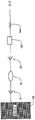
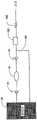
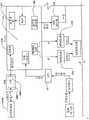
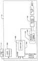
在本发明的一个实施例中,一种转发器系统被提供用于控制医疗器件。这种系统可以包括转发器和用户接口。所述转发器可以包括电路,(i)用于在给定范围上从至少一个可配戴医疗器件接收信号,(ii) 用于在给定范围上向可配戴医疗器件发射信号,(iii)用于在超过所述给定范围的较大范围上,向远离患者定位的用户接口发射所接收的信号,以及(iv)用于在所述较大范围上从用户接口接收信号。所述用户接口可以包括电路,(i)用于从转发器接收信号,以及(ii)用于向转发器发射信号。所述医疗器件可以是可配戴或者移植器件。In one embodiment of the invention, a transponder system is provided for controlling a medical device. Such a system may include a repeater and a user interface. The repeater may include circuitry for (i) receiving signals from at least one wearable medical device over a given range, (ii) transmitting signals to the wearable medical device over a given range, (iii) ) for transmitting received signals over a larger range beyond said given range to a user interface located remote from the patient, and (iv) for receiving signals from the user interface over said larger range. The user interface may include circuitry (i) for receiving signals from the repeater and (ii) for transmitting signals to the repeater. The medical device may be a wearable or implantable device.
在一些实施例中,用户接口的电路也可以被提供用于从可配戴器件直接接收信号以及向可配戴器件直接发射信号。而且,转发器的电路可以适于从多个医疗器件接收信号。In some embodiments, circuitry of the user interface may also be provided for receiving signals directly from and transmitting signals directly to the wearable device. Furthermore, the circuitry of the repeater may be adapted to receive signals from a plurality of medical devices.
在一些实施例中,所述转发器可以包括以下部件中的一个或者多个:用于记录所接收数据的存储器、用于关于故障状态存在性而分析所接收数据的处理器,以及用于通知用户故障状态存在的警报器。所述故障状态可以包括发生如下事件,其中,转发器与可配戴医疗器件分离的距离大于给定范围。In some embodiments, the repeater may include one or more of the following components: a memory for recording received data, a processor for analyzing the received data regarding the existence of fault conditions, and a notification Alerter for the presence of a user failure state. The fault condition may include the occurrence of an event wherein the transponder is separated from the wearable medical device by a distance greater than a given range.
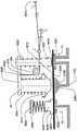
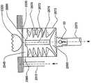
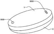
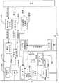
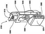
在本发明的一个实施例中,转发器适于控制目标体上所配戴的贴片大小的泵,从而向所述受验体输送流体。在该实施例中,转发器可以具有电路,(i)用于在给定范围上从泵接收信号,所接收的信号含有与由泵输送的流体体积有关的以及与警报状态有关的数据,以及(ii) 用于在超过所述给定范围的较大范围上向用于监视输送流体体积以及警报状态的接口发射所接收的信号。这种转发器的电路也可以提供用于在较大范围上从所述接口接收控制信号,所述控制信号含有用于控制泵的控制信息,并且用于在给定范围上向泵发射所述控制信号。In one embodiment of the invention, the transponder is adapted to control a patch-sized pump worn on the target body to deliver fluid to the subject. In this embodiment, the repeater may have circuitry for (i) receiving a signal from the pump over a given range, the received signal containing data related to the volume of fluid delivered by the pump and related to the alarm status, and (ii) for transmitting the received signal over a larger range beyond said given range to the interface for monitoring the volume of fluid delivered and the status of the alarm. Circuitry of such a repeater may also be provided for receiving control signals from the interface over a larger range, the control signals containing control information for controlling the pump, and for transmitting the said pump over a given range control signal.
这种转发器可以具有在上面关于转发器系统所描述的转发器的特性。除了或者替代对于发生其中转发器与可配戴医疗器件分离的距离大于给定范围的事件具有警报器,转发器还可以包括用于在泵中探测到流动堵塞或者气泡的警报器。Such a repeater may have the characteristics of the repeater described above with respect to the repeater system. In addition to or instead of having an alarm for events in which the transponder is separated from the wearable medical device by a distance greater than a given range, the transponder may also include an alarm for detecting flow blockages or air bubbles in the pump.
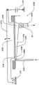
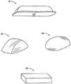
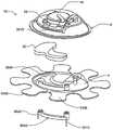
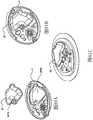
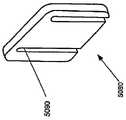
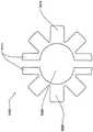
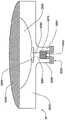
在本发明的另一实施例中,粘结剂贴片系统被提供用于向人体附着物体。这种粘结剂贴片系统可以包括两套粘结剂部件。在具有三个或者更多部件的第一套部件中,每一个部件均在至少一侧上包括粘结剂材料,从而在施加压力时附着到身体,围绕中央区域设置所述部件。类似地,在具有三个或者更多部件的第二套部件中,每一个部件均在至少一侧上包括粘结剂材料,从而在施加压力时附着到身体,围绕中央区域设置所述部件。第一套部件被隔开以允许第二套部件在第一套部件之间提供的空间中附着到身体,并且第二套部件被隔开以允许第一套部件在不使得第二套的部件脱离的情况下从身体脱离。In another embodiment of the present invention, an adhesive patch system is provided for attaching objects to the human body. This adhesive patch system may include two sets of adhesive components. In a first set of parts having three or more parts, each part including adhesive material on at least one side to adhere to the body when pressure is applied, the parts are positioned around a central area. Similarly, in a second set of parts having three or more parts, each part including adhesive material on at least one side to adhere to the body when pressure is applied, the parts are positioned around a central area. The first set of parts is spaced to allow the second set of parts to be attached to the body in the space provided between the first set of parts, and the second set of parts is spaced to allow the first set of parts Disengage from the body in the case of disengagement.
在粘结剂贴片系统的一个实施例中,至少一个部件被穿孔从而允许易于将所述部件撕下。将所述部件撕下可以减轻对在下面的皮肤的刺激。而且,所述中央区域适于固定可配戴医疗器件。所述粘结剂贴片可以是半圆形的。所述粘结剂贴片可以包括可剥离衬垫。所述粘结剂贴片系统的部件可以利用纤维被连结到中央区域。第一套的部件可以具有第一颜色而第二套的部件可以具有不同于第一颜色的第二颜色。In one embodiment of the adhesive patch system, at least one component is perforated to allow easy removal of the component. Tear-off the part can reduce irritation to the underlying skin. Furthermore, the central region is adapted to secure the wearable medical device. The adhesive patch may be semi-circular. The adhesive patch may include a release liner. The components of the adhesive patch system may be attached to the central region using fibers. The components of the first set may have a first color and the components of the second set may have a second color different from the first color.
这种粘结剂贴片系统可以被用于通过以下方法将物体接附到人体,所述方法包括以下步骤:提供具有三个或者更多部件的第一套部件(如上所指出地,其每一个部件在至少一侧上包括粘结剂材料从而当施加压力时附着到身体,围绕中央区域设置所述部件);将第一套部件附着到身体从而在每一个部件之间留出空间,以便将所述物体保持到身体;提供具有三个或者更多部件的第二套部件(其每一个部件在至少一侧上包括粘结剂材料从而当施加压力时附着到身体,围绕中央区域设置所述部件);在第一套部件之间的空间中将第二套部件附着到身体,从而利用第二套部件将物体保持到身体;并且在将第二套部件附着到身体之后,将第一套部件从身体移除。Such an adhesive patch system can be used to attach an object to a human body by a method comprising the steps of: providing a first set of parts having three or more parts (as noted above, each of which is one part includes adhesive material on at least one side to adhere to the body when pressure is applied, the parts are positioned around a central area); attaching a first set of parts to the body leaving space between each part for holding the object to the body; providing a second set of parts having three or more parts (each of which includes adhesive material on at least one side to adhere to the body when pressure is applied, disposing all parts around a central area; the second set of parts is attached to the body in the space between the first set of parts, thereby using the second set of parts to hold the object to the body; and after attaching the second set of parts to the body, the first set of parts is attached to the body The sleeve parts are removed from the body.
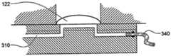
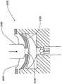
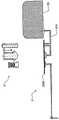
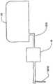
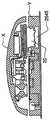
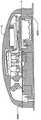
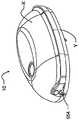
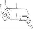
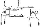
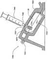
被接附的物体可以是通过皮肤向身体泵送治疗流体的泵。这种泵的套管可以穿过皮肤以允许通过皮肤从所述泵输送流体。在所述方法的优选实施例中,当第二套部件被附着到身体时以及当第一套部件被从身体移除时,所述套管不移动并且保持穿过皮肤。The attached object may be a pump that pumps therapeutic fluid through the skin to the body. The cannula of such a pump can be passed through the skin to allow fluid delivery from the pump through the skin. In a preferred embodiment of the method, the cannula does not move and remains through the skin when the second cover part is attached to the body and when the first cover part is removed from the body.
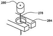
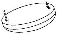
类似地,被接附的物体可以是用于通过皮肤测量身体中的参数的探针。这种探针可以穿过皮肤。在该方法的优选实施例中,当第二套部件被附着到身体时以及当第一套部件被从身体移除时,所述探针不移动并且保持穿过皮肤。Similarly, the attached object may be a probe for measuring parameters in the body through the skin. This probe can go through the skin. In a preferred embodiment of the method, the probe does not move and remains through the skin when the second cover part is attached to the body and when the first cover part is removed from the body.
在这种粘结剂贴片系统中被连结的物体可以设有空气通道,以当所述物体被附着到身体时允许空气在所述物体下面流向身体。Objects joined in such an adhesive patch system may be provided with air channels to allow air to flow under the object to the body when the object is attached to the body.
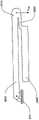
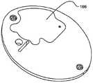
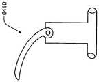
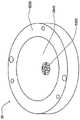
用于向人体附着物体的一种可替代粘结系统包括中央部件,该中央部件适于固定可配戴物体并且在至少一侧上具有粘结剂材料从而在施加压力时附着到身体,所述可替代粘结系统还包括多个外围部件,每一个部件均在至少一侧上包括粘结剂材料从而在施加压力时附着到身体,其中纤维性的连接器被提供用于将每一个外围部件连接到中央部件。在优选实施例中,所述纤维性的连接器是弹性的。An alternative adhesive system for attaching objects to the human body includes a central member adapted to secure the wearable object and having adhesive material on at least one side to adhere to the body upon application of pressure, the The alternative adhesive system also includes a plurality of peripheral components, each component including adhesive material on at least one side to adhere to the body upon application of pressure, wherein a fibrous connector is provided for attaching each peripheral component connected to the central part. In a preferred embodiment, the fibrous connector is elastic.
在本发明的一个实施例中,提供一种用于利用治疗液体填充储液器的方法。这种方法可以包括提供一种填充站,所述填充站具有用于保持储液器处于倾斜的基本刚性的填充站基部,以及连结到填充站基部的基本刚性的填充站盖部。所述填充站盖部具有用于从注射器接收流体的填充孔。所述填充站盖部和填充站基部限定一定容积,从而防止对所述储液器过度填充。这种方法还包括将储液器置于所述填充站中、在所述储液器上关闭所述填充站盖部、向填充孔施加含有治疗液体的注射器,并且通过所述填充孔将治疗液体从注射器注射到储液器中。在优选实施例中,移除在注射步骤之后的储液器中的任何空气。窗口可以被设于所述填充站盖部中,以查看储液器中的液体量。可以通过比较通过所述窗口查看到的液体水平与流体水平标记而估计液体量。In one embodiment of the present invention, a method for filling a reservoir with a therapeutic liquid is provided. The method may include providing a filling station having a substantially rigid filling station base for holding the reservoir in a tilted position, and a substantially rigid filling station cover attached to the filling station base. The fill station cover has fill holes for receiving fluid from a syringe. The filling station cover and the filling station base define a volume to prevent overfilling of the reservoir. The method also includes placing a reservoir in the filling station, closing the filling station cover on the reservoir, applying a syringe containing a treatment liquid to a filling hole, and injecting a treatment through the filling hole Liquid is injected from a syringe into a reservoir. In a preferred embodiment, any air in the reservoir after the injection step is removed. A window may be provided in the filling station cover to view the amount of liquid in the reservoir. The amount of fluid can be estimated by comparing the fluid level viewed through the window to the fluid level marker.
在本发明的一个实施例中,为贴片大小的输液器件提供基站,其中所述输液器件包括一次性部分和可再用部分,并且所述一次性部分和可再用部分能够经由与所述可再用部分相关联的连结机构而被相互连接。所述基站包括用于保持所述输液器件的可再用部分的接收器,所述接收器包括用于与可再用部分的连结机构相协作的部件。所述基站还可以包括用于对可再用部分中的蓄电池充电的充电器。所述基站还可以包括在独立的计算机和可再用部分之间的通信接口,从而向可再用部分上传信息或者从其下载信息。In one embodiment of the invention, a base station is provided for a patch-sized infusion device, wherein the infusion device includes a disposable portion and a reusable portion, and the disposable portion and the reusable portion are The reusable parts are connected to each other using the associated link mechanism. The base station includes a receiver for holding the reusable portion of the infusion set, the receiver including means for cooperating with the attachment mechanism of the reusable portion. The base station may also include a charger for charging batteries in the reusable portion. The base station may also include a communication interface between the stand-alone computer and the reusable part to upload information to or download information from the reusable part.
本发明的这些方面并非旨在是排他性的并且当与所附权利要求和附图相结合进行阅读时本领域普通技术人员易于理解本发明的其它特征、方面和优点。These aspects of the invention are not intended to be exclusive and other features, aspects and advantages of the invention will be readily apparent to those of ordinary skill in the art when read in conjunction with the appended claims and drawings.
附图说明Description of drawings
参考附图通过参考下面的详细说明,将更加易于理解本发明的前述特征,其中:The foregoing features of the present invention will be more readily understood by reference to the following detailed description with reference to the accompanying drawings, wherein:
图1描绘具有贴片和无线手持用户接口组件的患者;Figure 1 depicts a patient with a patch and a wireless handheld user interface assembly;
图2A是具有反馈控制的流体输送器件的概略图;2A is a schematic diagram of a fluid delivery device with feedback control;
图2B是具有反馈控制和储液器的流体输送器件的概略图;2B is a schematic diagram of a fluid delivery device with feedback control and reservoir;
图3是具有非加压储液器的流体输送器件的概略图;3 is a schematic diagram of a fluid delivery device with a non-pressurized reservoir;
图4A-4C是限流器的各种实施例的概略截面图;4A-4C are schematic cross-sectional views of various embodiments of flow restrictors;
图5示出与限流器串联的弹性分配组件;Figure 5 shows the elastic distribution assembly in series with the restrictor;
图6示出具有计量腔室和传感器的分配组件;Figure 6 shows a dispensing assembly with a metering chamber and sensor;
图7示出具有带分配弹簧的计量腔室和传感器的分配组件;Figure 7 shows a dispensing assembly with a metering chamber and sensor with a dispensing spring;
图8示出具有可替代声学路径的分配组件的截面视图;8 shows a cross-sectional view of a distribution assembly with alternative acoustic paths;
图9示出分配组件的概略视图;Figure 9 shows a schematic view of the dispensing assembly;
图10示出用于弹性可变容积分配腔室的膜片弹簧;Figure 10 shows a diaphragm spring for an elastic variable volume dispensing chamber;
图11A示出示例性基础流体输送的动力学分布;Figure 11A shows the kinetic profile of an exemplary base fluid delivery;
图11B示出示例性丸剂流体输送的动力学分布;Figure 11B shows the kinetic profile of an exemplary bolus fluid delivery;
图11C示出代表正常流体输送的动力学数据;Figure 11C shows kinetic data representative of normal fluid transport;
图11D-11F示出代表各种故障状态的动力学数据;Figures 11D-11F show kinetic data representing various failure states;
图12示出流体输送器件实施例的感测和反应过程的流程图;12 shows a flow diagram of the sensing and reaction process of an embodiment of a fluid delivery device;
图13示出具有压力产生组件的流动管线的框图;Figure 13 shows a block diagram of a flow line with a pressure generating assembly;
图14示出具有阀门泵的流动管线的框图;Figure 14 shows a block diagram of a flow line with a valve pump;
图15A-15D示出泵送机构的概略图;Figures 15A-15D show schematic views of the pumping mechanism;
图16示出泵送机构的概略图;Figure 16 shows a schematic diagram of the pumping mechanism;
图17概略示出能够具有多个泵送模式的包括形状记忆致动器的实施例的截面视图;17 schematically illustrates a cross-sectional view of an embodiment including a shape memory actuator capable of having multiple pumping modes;
图18概略示出包括两个形状记忆致动器并且能够具有多个泵送模式的实施例的截面视图;18 schematically illustrates a cross-sectional view of an embodiment that includes two shape memory actuators and is capable of multiple pumping modes;
图19概略示出包括不同长度的形状记忆致动器的实施例的截面视图;19 schematically illustrates a cross-sectional view of an embodiment including shape memory actuators of different lengths;
图20A-20B概略示出用于接附形状记忆致动器的实施例;20A-20B diagrammatically illustrate an embodiment for attaching a shape memory actuator;
图21A-21B概略示出用于将形状记忆致动器接附到泵送机构的实施例;21A-21B diagrammatically illustrate an embodiment for attaching a shape memory actuator to a pumping mechanism;
图22和23示出采用指状件的泵送机构;Figures 22 and 23 show a pumping mechanism employing fingers;
图24示出采用旋转凸起的泵送机构;Figure 24 shows a pumping mechanism employing a rotating protrusion;
图25示出采用柱塞和柱塞筒的泵送机构;Figure 25 shows a pumping mechanism employing a plunger and plunger barrel;
图26示出处于膨胀状态的形状记忆致动器的视图;Figure 26 shows a view of the shape memory actuator in an expanded state;
图27示出处于收缩状态的形状记忆致动器的视图;Figure 27 shows a view of the shape memory actuator in a retracted state;
图28示出采用柱塞和柱塞筒的泵送组件以及具有杠杆的形状记忆马达的视图;Figure 28 shows a view of a pumping assembly employing a plunger and plunger barrel and a shape memory motor with a lever;
图29示出采用柱塞和柱塞筒的泵送组件以及形状记忆马达的视图;Figure 29 shows a view of a pumping assembly employing a plunger and plunger barrel and a shape memory motor;
图30示出采用柱塞和柱塞筒的泵送器件以及在柱塞轴中具有导线的形状记忆马达的视图;Figure 30 shows a view of a pumping device employing a plunger and plunger barrel and a shape memory motor with wires in the plunger shaft;
图31示出具有组合泵和储液器的流动管线实施例;Figure 31 shows a flow line embodiment with a combined pump and reservoir;
图32概略示出处于停歇位置的阀门泵的截面视图;Figure 32 schematically shows a cross-sectional view of the valve pump in a rest position;
图33概略示出处于中间位置的图32的阀门泵的截面视图;Figure 33 schematically shows a cross-sectional view of the valve pump of Figure 32 in an intermediate position;
图34概略示出处于致动位置的图32的阀门泵的截面视图;Figure 34 schematically shows a cross-sectional view of the valve pump of Figure 32 in an actuated position;
图35概略示出用于阀门泵的泵送膜片的截面视图;Figure 35 schematically shows a cross-sectional view of a pumping diaphragm for a valve pump;
图36示出用于泵送膜片的膜片弹簧的透视图;Figure 36 shows a perspective view of a diaphragm spring for a pumping diaphragm;
图37概略示出采用杠杆的阀门泵和形状记忆线致动器的截面视图;Figure 37 diagrammatically shows a cross-sectional view of a valve pump and shape memory wire actuator employing a lever;
图38概略示出包括采用弹性柱形屈曲的阀门泵的实施例的截面视图;38 schematically illustrates a cross-sectional view of an embodiment including a valve pump employing elastic cylindrical buckling;
图39概略示出包括具有弹性部件和刚性支撑件的阀门泵屈曲的实施例的截面视图;39 schematically illustrates a cross-sectional view of an embodiment including buckling of a valve pump with elastic members and rigid supports;
图40概略示出在柔性隔膜上游具有膜片弹簧的处于停歇状态中的阀门泵的截面视图;40 schematically shows a cross-sectional view of a valve pump in a resting state with a diaphragm spring upstream of a flexible diaphragm;
图41概略示出处于中间状态的图40的阀门泵的截面视图;Figure 41 schematically shows a cross-sectional view of the valve pump of Figure 40 in an intermediate state;
图42概略示出处于致动状态的图40的阀门泵的截面视图;42 schematically shows a cross-sectional view of the valve pump of FIG. 40 in an actuated state;
图43概略示出在柔性隔膜上游具有膜片弹簧的阀门泵的截面视图,其中柔性隔膜周向地接附到作用力施加部件;43 schematically shows a cross-sectional view of a valve pump with a diaphragm spring upstream of a flexible diaphragm, wherein the flexible diaphragm is circumferentially attached to a force applying member;
图44概略示出在柔性隔膜上游具有膜片弹簧的阀门泵的截面视图,它包括用于传递作用力的刚性球;Figure 44 schematically shows a cross-sectional view of a valve pump with a diaphragm spring upstream of a flexible diaphragm, which includes a rigid ball for transmitting force;
图45概略示出包括具有弹性泵叶片的阀门泵的实施例的截面视图;45 schematically illustrates a cross-sectional view of an embodiment including a valve pump with resilient pump vanes;
图46概略示出包括用于阀门泵的可替代形式的弹性泵叶片的实施例的截面视图;46 schematically illustrates a cross-sectional view of an embodiment including an alternative form of resilient pump vanes for a valve pump;
图47概略示出包括具有多个作用力施加部件的阀门泵的实施例的截面视图;Figure 47 schematically illustrates a cross-sectional view of an embodiment including a valve pump having multiple force applying components;
图48概略示出处于停歇或者填充模式的包括直角杠杆驱动阀门泵和偏流阀的泵送机构;Figure 48 diagrammatically shows a pumping mechanism including a right angle lever actuated valve pump and a bias valve in a rest or fill mode;
图49概略示出处于致动状态的图48的泵送机构。Figure 49 diagrammatically shows the pumping mechanism of Figure 48 in an actuated state.
图50概略示出根据本发明实施例具有升高的阀座并且处于关闭位置的偏流阀的截面视图;50 schematically illustrates a cross-sectional view of a biasing valve having a raised valve seat and in a closed position in accordance with an embodiment of the present invention;
图51概略示出处于打开位置的图50的偏流阀的截面视图;FIG. 51 schematically shows a cross-sectional view of the diverter valve of FIG. 50 in an open position;
图52概略示出根据本发明实施例不具有升高的阀座并且处于打开位置的偏流阀的截面视图;Figure 52 schematically illustrates a cross-sectional view of a biasing valve without a raised valve seat and in an open position in accordance with an embodiment of the present invention;
图53概略示出处于关闭位置的图52的偏流阀的截面视图;'Fig. 53 schematically shows a cross-sectional view of the diverter valve of Fig. 52 in a closed position;'
图54概略示出根据本发明实施例作用于阀门出口附近的提升阀上的作用力;Figure 54 diagrammatically illustrates the force acting on a poppet valve near the valve outlet in accordance with an embodiment of the present invention;
图55以详细视图概略示出根据本发明实施例作用于阀门进口附近的提升阀上的作用力;Figure 55 diagrammatically illustrates, in a detailed view, the forces acting on a poppet valve near the valve inlet in accordance with an embodiment of the present invention;
图56概略示出根据本发明实施例具有可调节开启压力的偏流阀;Figure 56 diagrammatically illustrates a bias valve with adjustable cracking pressure in accordance with an embodiment of the present invention;
图57和58示出利用非加压储液器的流动管线的概略图;Figures 57 and 58 show schematic diagrams of flow lines utilizing a non-pressurized reservoir;
图59A-59E示出在流体输送器件中的流体流动的概略图;Figures 59A-59E show schematic diagrams of fluid flow in a fluid delivery device;
图60A-60D示出在流体输送器件中的流体流动的分解概略图;Figures 60A-60D show exploded schematic views of fluid flow in a fluid delivery device;
图61A-61C示出在流体输送器件中的流体流动的概略图;61A-61C show schematic diagrams of fluid flow in a fluid delivery device;
图62A和62B示出独立器件的概略图;Figures 62A and 62B show schematic diagrams of stand-alone devices;
图63A-63C示出器件实施例的截面概略图;63A-63C show schematic cross-sectional views of device embodiments;
图64A-64D示出器件实施例的截面概略图;64A-64D show cross-sectional schematic views of device embodiments;
图65A-65B示出连接到流动管线的输液器件的实施例的截面概略图;65A-65B show cross-sectional schematic views of an embodiment of an infusion device connected to a flow line;
图66A-66D示出将储液器插入器件中的序列的截面概略图;Figures 66A-66D show schematic cross-sectional views of the sequence of inserting a reservoir into a device;
图67A-67F示出流体输送器件的实施例的概略图;67A-67F show schematic diagrams of embodiments of fluid delivery devices;
图68是连接到患者的器件的便携式泵实施例的一个实施例的概略图;Figure 68 is a schematic diagram of one embodiment of a portable pump embodiment connected to a patient's device;
图69A-69B示出器件的壳体下侧的概略视图;Figures 69A-69B show schematic views of the underside of the housing of the device;
图70-70D是描绘在流体输送器件实施例中可用的各种构件的视图;70-70D are views depicting various components that may be used in fluid delivery device embodiments;
图71概略示出可以被组装以形成根据器件实施例的流体输送器件的构件;Figure 71 diagrammatically illustrates components that may be assembled to form a fluid delivery device according to an embodiment of the device;
图72示出具有声学体积测量构件的流体输送器件的侧视图;Figure 72 shows a side view of a fluid delivery device with an acoustic volume measurement member;
图73示出用于声学体积测量的印刷电路板;Figure 73 shows a printed circuit board for acoustic volume measurement;
图74示出器件实施例的图示视图;Figure 74 shows a diagrammatic view of a device embodiment;
图75示出流体输送器件的实施例的图示截面视图;Figure 75 shows a diagrammatic cross-sectional view of an embodiment of a fluid delivery device;
图76示出流体输送器件的实施例的分解图示视图;Figure 76 shows an exploded diagrammatic view of an embodiment of a fluid delivery device;
图77示出可以被组装以形成流体输送器件的一个实施例的构件的分解视图;Figure 77 shows an exploded view of components that may be assembled to form one embodiment of a fluid delivery device;
图78示出流体输送器件的实施例的分解视图;Figure 78 shows an exploded view of an embodiment of a fluid delivery device;
图79示出流体输送器件的一个实施例的基部的顶视图;Figure 79 shows a top view of the base of one embodiment of a fluid delivery device;
图80示出流体输送器件的一个实施例的顶部的下侧;Figure 80 shows the underside of the top of one embodiment of the fluid delivery device;
图81A-81C示出用于表示在顶部和基部之间夹住储液器20的过程的序列;81A-81C show a sequence used to represent the process of clamping the
图82示出器件的分解顶视图;Figure 82 shows an exploded top view of the device;
图83示出器件的一个实施例的底部的分解视图,其中示出流体路径组件、底部壳体和隔膜以及粘结剂;Figure 83 shows an exploded view of the bottom of one embodiment of the device showing the fluid path assembly, bottom housing and diaphragm, and adhesive;
图84示出基部的底视图,其中示出流体路径组件的底视图;Figure 84 shows a bottom view of the base showing a bottom view of the fluid path assembly;
图85A-85D示出器件实施例的分解、局部分解以及非分解视图;85A-85D illustrate exploded, partially exploded, and non-exploded views of device embodiments;
图86A示出具有输液器件以及所连接的分析物传感器的输液和传感器组件的概略图;Figure 86A shows a schematic diagram of an infusion and sensor assembly with an infusion device and an attached analyte sensor;
图86B示出具有引入针的如图86A所示的输液和传感器组件的分解视图;Figure 86B shows an exploded view of the infusion and sensor assembly shown in Figure 86A with an introduction needle;
图87A-87E示出输液和传感器组件的实施例被插入器件中的序列;87A-87E illustrate the sequence in which an embodiment of an infusion and sensor assembly is inserted into a device;
图88A-88B示出在输液和传感器组件的序列中的插入器器件的一个实施例;88A-88B illustrate one embodiment of an inserter device in a sequence of infusion and sensor assemblies;
图88C-88D示出图88A-88B的插入器的局部剖视图;Figures 88C-88D show partial cross-sectional views of the inserter of Figures 88A-88B;
图89A示出用于插入输液和传感器组件的插入器器件的一个实施例的前视图;Figure 89A shows a front view of one embodiment of an inserter device for inserting an infusion and sensor assembly;
图89B示出图89A的插入器件的后视图;Figure 89B shows a rear view of the insert device of Figure 89A;
图90示出用于输液和传感器组件的药筒的一个实施例的透视图;Figure 90 shows a perspective view of one embodiment of a cartridge for an infusion and sensor assembly;
图91A-91C示出用于插入输液和传感器组件的插入器器件的前透视图和侧透视图;91A-91C show front and side perspective views of an inserter device for inserting an infusion and sensor assembly;
图92A-92F概略示出用于操作插入器机构的一个实施例的时序序列;Figures 92A-92F diagrammatically illustrate a timing sequence for operating one embodiment of the inserter mechanism;
图92G示出在关闭位置中的具有制动件(catch)和压簧杠杆的插入器机构;Figure 92G shows the inserter mechanism with a catch and a compression spring lever in a closed position;
图92H示出在打开位置中的具有制动件和压簧杠杆的插入器机构;Figure 92H shows the inserter mechanism with detent and compression spring lever in the open position;
图93A-93C示出用于将套管插入流体输送器件基部的时间序列;93A-93C show a time series for inserting a cannula into the base of a fluid delivery device;
图94A-94C示出用于在将套管一致地连接到流动管线时将套管插入基部的时序序列;Figures 94A-94C illustrate a timing sequence for inserting the cannula into the base when the cannula is congruently connected to the flow line;
图95示出用于保持流体输送器件的粘结剂贴片的顶视图;Figure 95 shows a top view of an adhesive patch for holding a fluid delivery device;
图96概略示出在粘结剂贴片下面的流体输送器件的截面视图;Figure 96 schematically shows a cross-sectional view of the fluid delivery device beneath the adhesive patch;
图97示出用于保持流体输送器件的两个交叠粘结剂贴片的透视图;Figure 97 shows a perspective view of two overlapping adhesive patches for holding a fluid delivery device;
图98示出两个半圆形粘结剂贴片部分的顶视图;Figure 98 shows a top view of two semicircular adhesive patch sections;
图99示出保持流体输送器件的两个半圆形粘结剂贴片部分的透视图;Figure 99 shows a perspective view of two semicircular adhesive patch portions holding a fluid delivery device;
图100示出被患者移除的半圆形粘结剂贴片部分的透视图;Figure 100 shows a perspective view of a portion of a semicircular adhesive patch removed by a patient;
图101示出使用多个粘结剂部件和系绳而附于患者的流体输送器件的透视图;Figure 101 shows a perspective view of a fluid delivery device attached to a patient using multiple adhesive components and tethers;
图102A示出用于组装器件的夹具;Figure 102A shows a jig for assembling the device;
图102B示出具有用于插入夹具的键孔的流体输送器件的基部;Figure 102B shows the base of a fluid delivery device with a keyhole for insertion of a clamp;
图102C示出利用夹具组装的流体输送器件的截面视图;102C shows a cross-sectional view of a fluid delivery device assembled with a clamp;
图103A示出用于组装流体输送器件的凸轮引导件的透视图;Figure 103A shows a perspective view of a cam guide for assembling a fluid delivery device;
图103B示出图103A的凸轮引导件的顶视图;Figure 103B shows a top view of the cam guide of Figure 103A;
图103C示出用于组装流体输送器件的夹销的透视图;Figure 103C shows a perspective view of a clip pin used to assemble a fluid delivery device;
图103D示出使用夹销和凸轮引导件组装的流体输送器件的实施例;Figure 103D shows an embodiment of a fluid delivery device assembled using clip pins and cam guides;
图104示出根据一个实施例的可塌陷储液器的截面视图;Figure 104 shows a cross-sectional view of a collapsible reservoir according to one embodiment;
图105示出图104的储液器的透视图;Figure 105 shows a perspective view of the reservoir of Figure 104;
图106A-106C示出根据一个实施例用于将隔膜固定到端帽以形成储液器的一系列步骤;106A-106C illustrate a series of steps for securing a septum to an end cap to form a reservoir according to one embodiment;
图107示出根据一个实施例的储液器填充站;Figure 107 illustrates a reservoir filling station according to one embodiment;
图108A-108B示出处于打开(108A)和关闭(108B)位置中的储液器填充站的实施例;Figures 108A-108B illustrate embodiments of the reservoir filling station in open (108A) and closed (108B) positions;
图109A示出用于流体输送系统的实施例的数据采集和控制方案的一个实施例的框图;Figure 109A shows a block diagram of one embodiment of a data acquisition and control scheme for an embodiment of a fluid delivery system;
图109B示出用于流体输送系统的实施例的数据采集和控制方案的一个实施例的框图Figure 109B shows a block diagram of one embodiment of a data acquisition and control scheme for an embodiment of a fluid delivery system
图110A示出描述根据一个实施例的流体输送器件的操作的流程图;Figure 110A shows a flow chart describing the operation of a fluid delivery device according to one embodiment;
图110B示出描述根据一个实施例的流体输送器件的操作的流程图;Figure 110B shows a flow chart describing the operation of a fluid delivery device according to one embodiment;
图111示出相互无线通信的用户接口和流体输送构件的框图;111 shows a block diagram of a user interface and fluid delivery components in wireless communication with each other;
图112示出数据流视图,所述视图示出根据一个实施例的中间收发器的使用;Figure 112 shows a data flow view illustrating the use of an intermediate transceiver according to one embodiment;
图113示出根据一个实施例的中间收发器的框图;Figure 113 shows a block diagram of an intermediate transceiver according to one embodiment;
图114示出根据一个实施例用于通用患者接口的数据流视图;Figure 114 illustrates a data flow view for a generic patient interface, according to one embodiment;
图115示出根据一个实施例的处于解耦状态的流体输送器件的非一次性部分和蓄电池充电器;115 illustrates the non-disposable portion of the fluid delivery device and battery charger in an uncoupled state, according to one embodiment;
图116示出根据一个实施例的处于对接状态的图115的流体输送器件的非一次性部分和蓄电池充电器;并且Figure 116 illustrates the non-disposable portion and battery charger of the fluid delivery device of Figure 115 in a docked state, according to one embodiment; and
图117是描绘根据本发明实施例用于测量在泵冲程中输送的液体体积的过程的流程图。117 is a flow diagram depicting a process for measuring the volume of liquid delivered in a pump stroke in accordance with an embodiment of the present invention.
应该理解以上的图以及在其中描绘的元件未必按照一致的比例或者以任何比例绘制。It should be understood that the above figures, and the elements depicted therein, are not necessarily drawn to scale or to any scale.
具体实施方式Detailed ways
定义。如在本说明和所附权利要求中所使用的,下面的术语将具有所示意的含义,除非上下文另外要求:definition. As used in this specification and the appended claims, the following terms will have the meanings indicated, unless the context requires otherwise:
器件的“用户输入”包括器件用户或者其它操作员能够用来控制器件功能的任何机构。用户输入可以包括机械装置(例如开关,压钮)、用于与远程控制器通信的无线接口(例如RF、红外)、声学接口(例如带有语音识别)、计算机网络接口(例如USB端口)以及其它类型的接口。"User input" to a device includes any mechanism that a user or other operator of the device can use to control the function of the device. User input may include mechanical devices (eg, switches, push buttons), wireless interfaces (eg, RF, infrared) for communicating with remote controls, acoustic interfaces (eg, with voice recognition), computer network interfaces (eg, USB ports), and other types of interfaces.
与用户输入有关的“按钮”,例如在下面讨论的所谓的“推注按钮 (bolusbutton)”,可以是能够执行所需功能的任何类型的用户输入,并且不限于压钮。A "button" associated with a user input, such as the so-called "bolus button" discussed below, may be any type of user input capable of performing the desired function, and is not limited to pressing a button.
“警报器”包括能够用来向用户或者第三方发出警报的任何机构。警报器可以包括听觉警报器(例如扬声器、蜂鸣器、语音发生器)、视觉警报器(例如LED、LCD屏)、触觉警报器(例如振动元件)、无线信号(例如针对远程控制器或者看管者的无线发射)或者其它机构。可以同时地、同步地或者顺序地使用多个机构发生警报,包括备用机构(例如,两个不同的音频警报器)或者互补机构(例如,音频警报器、触觉警报器和无线警报器)。"Alarm" includes any mechanism that can be used to alert a user or a third party. Alarms may include audible alarms (e.g. speakers, buzzers, voice generators), visual alarms (e.g. LEDs, LCD screens), tactile alarms (e.g. vibrating elements), wireless signals (e.g. for remote controls or attendants) wireless transmission of the user) or other mechanisms. Alarms may occur simultaneously, synchronously, or sequentially using multiple mechanisms, including alternate mechanisms (eg, two different audio sirens) or complementary mechanisms (eg, audible sirens, tactile sirens, and wireless sirens).
“流体”意指能够通过流动管线流动的物质,例如液体。"Fluid" means a substance, such as a liquid, capable of flowing through a flow line.
“阻抗”意指器件或者流动管线对于从中流过的流体流的阻碍。"Impedance" means the resistance of a device or flow line to the flow of fluid therethrough.
“润湿”描述在正常流体输送操作期间与流体形成直接接触的构件。因为流体不限于液体,“润湿”构件并非一定变得湿润。"Wetted" describes components that come into direct contact with the fluid during normal fluid delivery operations. Because fluids are not limited to liquids, a "wetted" member does not necessarily become wet.
“患者”包括从作为医疗处理的一部分的流体输送器件接收流体或者以其它方式接收流体的人或者动物。A "patient" includes a person or animal that receives fluid from or otherwise receives fluid from a fluid delivery device as part of a medical treatment.
“套管”意指能够向患者灌输流体的一次性器件。如在这里使用的套管能够指代传统的套管或者针。"Cannula" means a disposable device capable of infusing fluids into a patient. A cannula as used herein can refer to a conventional cannula or needle.
“分析物传感器”意指能够确定在患者中存在分析物的任何传感器。分析物传感器的实施例包括但不限于能够确定任何滤过性毒菌的、寄生的、细菌的或者化学的分析物的存在的传感器。术语分析物包括葡萄糖。分析物传感器可以与流体输送器件中的其它构件(例如,非一次性部分中的控制器)和/或与远程控制器通信。"Analyte sensor" means any sensor capable of determining the presence of an analyte in a patient. Examples of analyte sensors include, but are not limited to, sensors capable of determining the presence of any viral, parasitic, bacterial, or chemical analyte. The term analyte includes glucose. The analyte sensor may communicate with other components in the fluid delivery device (eg, a controller in the non-disposable portion) and/or with a remote controller.
“分配组件传感器”意指用于确定在分配腔室中存在的流体体积的机构。"Dispensing assembly sensor" means a mechanism for determining the volume of fluid present in the dispensing chamber.
“尖锐物”意指能够刺穿或者戳穿动物皮肤,特别地是人的皮肤的任何物体。尖锐物可以包括套管、套管插入器件、分析物传感器或者分析物传感器插入器件。例如,在药筒中可以分别地提供或者可以一起地提供多个尖锐物。"Sharps" means any object capable of piercing or piercing the skin of animals, especially human skin. The sharps may include cannulas, cannula insertion devices, analyte sensors, or analyte sensor insertion devices. For example, multiple sharps may be provided separately in the cartridge or may be provided together.
“一次性”指的是预期在固定时期中使用,然后被丢弃并且更换的部件、器件、部分或者其它类似的。"Disposable" refers to a component, device, part, or the like, which is intended to be used for a fixed period of time and then discarded and replaced.
“非一次性”指的是旨在具有不限使用时期的可再用部分。"Non-disposable" refers to a reusable portion that is intended to have an indefinite period of use.
“贴片大小”意指足够小的尺寸,以致于在输送所述器件中含有的物质期间利用例如粘结剂或者带子可以被固定到患者皮肤并且作为医疗器件而被配戴。小到可以用作移植物的医疗器件属于该定义的范围。"Patch size" means a size small enough that it can be secured to a patient's skin and worn as a medical device during delivery of substances contained in the device using, for example, an adhesive or tape. Medical devices small enough to be used as implants fall within the scope of this definition.
“通常存在的有限流阻”意指在流体输送的常规过程中,即,当不存在错误状态(例如,堵塞)时存在的有限流阻。"Limited flow resistance generally present" means the limited flow resistance that exists during the normal process of fluid delivery, ie, when no error conditions (eg, blockages) exist.
“无源”阻抗是在泵送循环期间不受有源控制的阻抗。A "passive" impedance is one that is not actively controlled during the pumping cycle.
“声学体积测量”意指使用例如在美国专利No.5,349,852和 5,641,892中描述的声学技术以及在这里描述的技术的有关体积的定量测量。"Acoustic volume measurement" means quantitative measurement of volume using, for example, acoustic techniques such as those described in U.S. Patent Nos. 5,349,852 and 5,641,892 and techniques described herein.
“温度传感器”包括用于测量温度并且向控制器传送温度信息的任何机构。该器件可以包括用于测量例如皮肤温度、AVS温度、环境温度和流体温度的一个或者更多温度传感器。A "temperature sensor" includes any mechanism for measuring temperature and communicating temperature information to a controller. The device may include one or more temperature sensors for measuring, for example, skin temperature, AVS temperature, ambient temperature, and fluid temperature.
在这里描述的器件、泵送机构、系统和方法的实施例涉及这样的流体输送,所述流体输送包括泵送和流体体积测量以及流体输送的致动和控制。所述器件的实施例包括用于流体输送的便携式或者非便携式器件。所述器件的一些实施例包括一次性的基部和非一次性的顶部。所述器件包括其中输液器件通过基部插入并且直接进入患者体内的实施例。这些器件实施例是贴片泵器件(patch pump device)。可以使用粘结剂、带子或者其它适当装置将贴片泵附着到患者。粘结剂可以具有保护性可剥离条带,所述条带可以在使用之前被移除以暴露出粘结剂。Embodiments of the devices, pumping mechanisms, systems and methods described herein relate to fluid delivery including pumping and fluid volume measurement as well as actuation and control of fluid delivery. Examples of the device include portable or non-portable devices for fluid delivery. Some embodiments of the device include a disposable base and a non-disposable top. The device includes embodiments in which the infusion device is inserted through the base and directly into the patient. Examples of these devices are patch pump devices. The patch pump may be attached to the patient using adhesive, tape, or other suitable means. The adhesive can have a protective peelable strip that can be removed prior to use to expose the adhesive.
然而,在其它实施例中,流体输送器件是其中管线被连接到流动管线的便携式器件。一般地,通过套管将管线连接到患者。However, in other embodiments, the fluid delivery device is a portable device in which the line is connected to the flow line. Typically, the line is connected to the patient through a cannula.
在其中使用一次性基部和非一次性顶部的一些实施例中,基部包括被润湿的部件,而非一次性顶部中所包括的部分通常为非润湿部件。In some embodiments in which a disposable base and a non-disposable top are used, the base includes wetted components, whereas the portions included in the non-disposable top are typically non-wetted components.
泵送机构的各种实施例包括上游进口阀、泵送致动部件、下游出口阀和可移动部件。在一些实施例中,使用相同器件实现泵送致动部件和下游阀门功能。泵送机构通过流动管线将流体从储液器泵送到出口。泵送机构通常与非加压储液器一起使用,然而,本发明范围不限于此。Various embodiments of the pumping mechanism include an upstream inlet valve, a pumping actuation member, a downstream outlet valve, and a movable member. In some embodiments, the same device is used to implement the pumping actuation component and downstream valve functions. A pumping mechanism pumps fluid from the reservoir to the outlet through the flow line. The pumping mechanism is typically used with a non-pressurized reservoir, however, the scope of the present invention is not limited in this regard.
在流体输送系统的一个实施例中,所述器件包括分析物传感器壳体。分析物传感器通过器件基部的分析物传感器壳体被引入患者体内。在这些实施例中,也通过器件基部的管罩引入输液器件。在这些实施例中,所述器件作为贴片泵被用户配戴。In one embodiment of the fluid delivery system, the device includes an analyte sensor housing. The analyte sensor is introduced into the patient through the analyte sensor housing at the base of the device. In these embodiments, the infusion device is also introduced through the tube cover at the base of the device. In these embodiments, the device is worn by the user as a patch pump.
所述系统一般地包括控制器,所述控制器可以包括无线收发器。因此,通过无线控制器器件可以完全地或者部分地控制所述器件。控制器器件可以通过无线通信从分析物传感器和/或流体输送器件接收信息。患者或者第三方能够使用所述控制器器件控制流体输送器件的功能。The system generally includes a controller, which may include a wireless transceiver. Thus, the device can be fully or partially controlled by the wireless controller device. The controller device may receive information from the analyte sensor and/or the fluid delivery device via wireless communication. A patient or a third party can use the controller device to control the function of the fluid delivery device.
在流体输送器件的一个实施例中,所述器件是胰岛素泵并且所述分析物传感器是血液葡萄糖传感器。接收与输送的胰岛素体积(或者在一定时间期间泵冲程的数目)和血液葡萄糖数据有关的信息的控制器有助于用户对所述泵机构的致动时间表进行编程。In one embodiment of the fluid delivery device, the device is an insulin pump and the analyte sensor is a blood glucose sensor. A controller that receives information about the volume of insulin delivered (or the number of pump strokes over a period of time) and blood glucose data facilitates the user to program the actuation schedule of the pump mechanism.
在这里描述示例性的分配组件和体积感测器件。分配组件包括至少一个麦克风和扩音器。所述组件确定分配腔室中的体积改变以确定被泵送的流体体积。体积感测数据被用于确定流体输送器件的状态。因此,各种控制可以依赖于体积感测数据。Exemplary dispensing assemblies and volume sensing devices are described herein. The distribution assembly includes at least one microphone and a loudspeaker. The assembly determines the volume change in the dispensing chamber to determine the volume of fluid being pumped. Volume sensing data is used to determine the state of the fluid delivery device. Accordingly, various controls may rely on volume sensing data.
在本发明的实施例中,用户经由用户接口配置流体输送器件,从而使得流体输送器件以适当方式输送流体。在一个实施例中,用户接口为可以与所述贴片无线通信的独立的手持式用户接口组件。所述贴片可以是一次性的,或者部分地一次性的。In embodiments of the invention, the user configures the fluid delivery device via the user interface so that the fluid delivery device delivers fluid in an appropriate manner. In one embodiment, the user interface is a separate handheld user interface component that can communicate wirelessly with the patch. The patch may be disposable, or partially disposable.
如上所述,所述器件实施例的示例性用途是用于向糖尿病患者输送胰岛素,但是其它用途包括输送任何流体。流体包括用于疼痛患者的镇痛剂、用于癌症患者的化学疗法以及用于代谢紊乱患者的酶。各种治疗流体可以包括小分子、天然产品、缩氨酸、蛋白质、核酸、碳水化合物、纳米颗粒悬浮液以及有关的在药物学方面可以接受的载体分子。治疗活性分子可以被改性以提高输送器件中的稳定性(例如,通过缩氨酸或者蛋白质的聚乙二醇化(PEG化))。虽然这里的示意性实施例描述药品输送应用,但是实施例可以被用于其它应用,包括用于高输出量的分析测量(例如缩微实验室技术应用和毛细管色谱分析)的试剂的液体分配。为了下面说明的目的,术语“治疗剂”或者“流体”被互换地使用,然而,在其它实施例中,能够使用如上所述的任何流体。因此,在这里包括的器件和说明不限于治疗用途。As noted above, an exemplary use of the device embodiments is for the delivery of insulin to diabetic patients, but other uses include the delivery of any fluid. Fluids include analgesics for patients with pain, chemotherapy for cancer patients, and enzymes for patients with metabolic disorders. Various therapeutic fluids can include small molecules, natural products, peptides, proteins, nucleic acids, carbohydrates, nanoparticle suspensions, and related pharmaceutically acceptable carrier molecules. Therapeutically active molecules can be modified to improve stability in the delivery device (eg, by pegylation of peptides or proteins (PEGylation)). Although the illustrative embodiments herein describe drug delivery applications, embodiments may be used in other applications, including liquid dispensing of reagents for high-throughput analytical measurements, such as microscale laboratory technology applications and capillary chromatography. For the purposes of the description below, the terms "therapeutic agent" or "fluid" are used interchangeably, however, in other embodiments, any of the fluids described above can be used. Accordingly, the devices and instructions included herein are not limited to therapeutic use.
典型实施例包括用于保持流体供应的储液器。在胰岛素的情形中,储液器可以被方便地设为具有能够保持足以在一天或者多天中输送的胰岛素供应的尺寸。例如,储液器可以容纳大约1到2ml的胰岛素。对于大约90%的潜在用户,2ml胰岛素储液器可以相应于大约3天的供给。在其它实施例中,储液器能够具有任何尺寸或者形状并且能够适于容纳任何数量的胰岛素或者其它流体。在一些实施例中,储液器的尺寸和形状与储液器适于容纳的流体类型有关。流体储液器可以具有偏心的或者不规则的形状和/或可以被锁上从而防备错误安装或者使用。Typical embodiments include a reservoir for maintaining a fluid supply. In the case of insulin, the reservoir may conveniently be sized to maintain a sufficient supply of insulin to be delivered over one or more days. For example, the reservoir can hold approximately 1 to 2 ml of insulin. For about 90% of potential users, a 2ml insulin reservoir may correspond to about a 3 day supply. In other embodiments, the reservoir can be of any size or shape and can be adapted to hold any amount of insulin or other fluid. In some embodiments, the size and shape of the reservoir is related to the type of fluid the reservoir is suitable for holding. The fluid reservoir may have an eccentric or irregular shape and/or may be keyed to prevent incorrect installation or use.
流体输送器件的一些实施例适用于糖尿病患者使用,因此,在这些实施例中,器件输送用于补充或者更换患者胰岛β细胞的胰岛素。适用于胰岛素输送的实施例试图通过提供基础水平的流体输送以及推注水平的输送而模拟胰腺作用。通过使用无线手持式用户接口能够由患者或者另一方设定基础水平、推注水平和定时。另外地,能够响应一体的或者外部的分析物传感器(例如葡萄糖监视器件或者血液葡萄糖传感器)的输出而触发或者调节基础和/或推注水平。在一些实施例中,能够使用位于流体输送器件上的规定按钮或者其它输入装置由患者或者第三方触发推注。在另外的实施例中,推注或者基础水平能够通过位于流体输送器件上的用户接口被编程或者管理。Some embodiments of the fluid delivery device are suitable for use by diabetic patients, thus, in these embodiments, the device delivers insulin for replenishing or replacing the patient's pancreatic beta cells. Embodiments suitable for insulin delivery attempt to mimic pancreatic action by providing basal levels of fluid delivery as well as bolus level delivery. Basal levels, bolus levels and timing can be set by the patient or another party using a wireless handheld user interface. Additionally, basal and/or bolus levels can be triggered or adjusted in response to the output of an integrated or external analyte sensor (eg, a glucose monitoring device or blood glucose sensor). In some embodiments, the bolus can be triggered by the patient or a third party using a prescribed button or other input device located on the fluid delivery device. In further embodiments, the bolus or basal level can be programmed or administered through a user interface located on the fluid delivery device.
根据本发明示例性实施例,图1示出配戴流体输送器件10并且握持用于监视和调节流体输送器件10的操作的无线用户接口组件14的患者12。用户接口组件14一般地包括用于输入信息(例如触摸屏或者小键盘)以及用于向用户传递信息的设备(例如LCD显示器、扬声器或者振动警报器)。流体输送器件一般足够小和轻,从而在数日中保持舒适地附着到患者。FIG. 1 shows a patient 12 wearing a
在图1中,流体输送器件10被示为配戴在患者12的手臂上。在其它实施例中,流体输送器件10可以被配戴在患者身上的其它位置处,在这些位置处患者身体能够有利地利用被输送的特殊流体。例如,流体可以被有利地输送到患者腹部区域、腰部区域、腿或者其它部位。In FIG. 1 , the
现在参考图2A,示出流体输送器件10的概略示意图,该器件具有从分配组件120到泵送组件16的反馈环360。泵送组件16向分配组件120泵送流体;流体然后通过包括限流器340和输出部的出口组件 17离开。所述输出部一般地包括套管并且通向患者。分配组件120可以包括弹性的可变容积分配腔室以及至少一个麦克风和扩音器,用于测量与随着时间通过所述输出部的流有关的参数。反馈环360使得可以基于由传感器进行的重复测量而调节泵送组件16的操作。限流器340 在分配组件120和流动管线5010的输出部之间形成高阻抗。限流器340 可以例如是窄孔管或者微管的一部分。Referring now to FIG. 2A , there is shown a generalized schematic diagram of the
现在参考图2B,在一个实施例中,泵送组件16将流体从储液器 20泵送到分配组件120。Referring now to FIG. 2B , in one embodiment, the pumping
现在参考图3,示出采用流体力学原理的另一实施例的框图。流动管线310联接储液器20、泵送组件16、分配组件120以及出口组件 17。出口组件17可以包括高阻抗限流器340和输液器件5010,例如套管。限流器340的输出被送至输液器件5010,以便输送给患者。限流器340具有比流动管线310的位于分配组件120上游的部分更高的流阻。因此,泵送组件16能够比流体能离开出口组件17的情况更快地将流体泵送到分配组件120中。分配组件120可以包括具有弹性壁的可变容积分配腔室122。在下面给出的实施例中,弹性壁是隔膜。隔膜材料的实例包括硅树脂、NITRILE以及具有用于如在这里所述的发挥作用的所需弹性和特性的任何其它材料。另外地,其它结构可以用于相同目的。当由于泵送组件16的作用而接收到流体供给时,隔膜弹性将允许腔室122首先膨胀并且然后提供驱动分配组件120的流体内容物经过限流器340到达患者所需的输送压力。当配备有适当传感器(在下面描述其实例)时,分配组件120可以测量通过可变容积分配腔室 122的流体流并且可以通过反馈环360提供反馈以控制泵送组件16泵送或者部分地填充分配腔室122的定时和/或速率,由此以所需速率向患者输送所需剂量。Referring now to FIG. 3, a block diagram of another embodiment employing the principles of fluid mechanics is shown.
再次参考图3,另外地,限流器340防止流体流超过规定流率。进而,因为通过泵送组件16、分配组件120和限流器340的交互作用而完成加压流体输送,因此能够采用非加压储液器20。Referring again to Figure 3, additionally, the
仍然参考图3,反馈环360可以包括控制器501。控制器501可以包括处理器和用于致动泵送组件16以向分配组件120泵送流体的控制电路。控制器501从可以与分配组件120一体形成的传感器重复地接收与流体流有关的参数,并且使用该参数控制泵送组件16以实现通过输出部的所期望流动。例如,控制器501能够调节泵送组件16的致动定时或者程度,以实现所需的基础或者推注流率和/或输送所需的基础或者推注累积剂量。在确定泵送的定时或者程度时,控制器501可以使用传感器的输出(未示出)以估计流体流的速率、累积流量或者二者(以及很多其他量),并且然后基于所述估计确定适当的补偿行为。在各种实施例中,可以脉冲地进行泵送,其能够以在10-9升每脉冲到微升每脉冲之间的任何速率进行输送。可以通过输送多个脉冲来实现基础或者推注剂量。(在下面示出并且描述基础和推注剂量的实例)。Still referring to FIG. 3 ,
使用局部可塌陷的非加压储液器20可以有利地防止当储液器中的流体耗尽时在储液器中积累空气。储液器20可以通过隔膜(未示出) 被连接到流动管线310。在通气储液器中空气积累能够防止流体从储液器20流出,特别是当系统被倾斜使得在储液器中含有的流体和储液器 20的隔膜之间介入空气包时。在如可配戴器件的正常操作期间,希望系统被倾斜。图104-106C描绘了储液器的一个实施例的各种实施例和视图。另外地,在下面包括对储液器进一步的说明。The use of a partially collapsible,
现在参考图4A-4C,示出限流器340的各种实施例。现在参考图 4A,限流器是模制流道340,它可以是在基部中的模制凹槽(未示出)。在一个实施例中,模制流道340的截面大致为0.009英寸。在该实施例中,限流器340被模制到设备中。现在参考图4B,作为限流器的可替代实施例示出微管340。在一个实施例中,微管具有大致0.009英寸的内径。模制流道和微管均使用具有小内径或者截面的长路径以给予流阻。现在参考图4C,示出了作为限流器340的精确孔板。在一个实施例中,精确孔板是具有激光钻孔的板。在可替代实施例中,可以使用在本领域中已知的任何流阻器件或者方法。与具有可能通常被认为在功能意义上形成无限流阻的有源下游阀的现有技术流体输送系统不同,限流器340形成有限流阻。与可能有时由于堵塞而被阻碍的现有技术系统不同,本发明的阻抗在正常情况时也是存在的。由于流阻的有限性,在包括分配腔室122的实施例中,即使当分配腔室122膨胀时,流体也可能通过出口泄露。Referring now to FIGS. 4A-4C, various embodiments of the
图5-8概略示出分配组件120的示意性实施例的截面视图。应该理解,用于其它目的(例如工业过程)的流体输送属于本发明范围,并且以具体术语给出的说明仅仅是实例方式的。如图5所示,分配组件120可以包括可变容积分配腔室122和传感器550。可变容积分配腔室122包括弹性分配膜片125,它允许腔室122根据进出分配组件120 的流体流而膨胀和收缩。在本发明的某些实施例中,如将在这里进一步讨论地,可变容积分配腔室122可以被从分配组件120的其它元件拆离。利用双头箭头示出了允许腔室122膨胀和收缩的弹性分配膜片 125的概念。计量腔室122被认为包括了在图5中利用箭头112指定的具有流体流特征的线路110的一部分。流体流112或者线路110的终止的位置或者特性均不限制如所附权利要求明确要求保护的本发明的范围。相比于当被泵送组件16泵送入腔室122时流体进入腔室122的情况,限流器340使得流体更加缓慢地离开分配腔室122。结果,当流体供给进入时,分配腔室122膨胀并且被加压。由于分配腔室122的膨胀而变形的分配膜片125提供了输送计量体积使其经过限流器340 而到达出口组件17所需的作用力。如以上所讨论,传感器550重复地测量能够与弹性分配腔室122的容积相关的参数,例如位移、或者热力学变量或者容量。通过传感器550产生的体积测量可以用于通过反馈环控制泵送组件向分配腔室122泵送流体的定时和速率,从而适当的流体流被输送到出口组件17以及随后的管线,并且由此例如被输送到患者。传感器550可以采用例如声学体积感测(在下面更加详细地描述)或者用于确定体积或者体积相关参数的其它方法(光学或者电容性,作为其它实例)。声学体积测量技术是授予DEKA Products Limited Partnership的美国专利No.5,575,310和5,755,683以及于2006 年4月5日提交的题目为“用于流动控制的体积测量方法”、系列号为No.60/789,243的共同待审临时美国专利申请的主题,它们均通过引用方式而被结合在这里。利用该实施例能够在纳升范围中进行流体体积感测,因此有助于高度准确和精确地监视与输送。也可以使用用于测量流体流的其它可替代技术;例如,基于Doppler(多普勒)的方法;使用与叶片阀或者挡板阀相组合的Hall(霍尔)效应传感器;使用应变梁(例如,与流体腔室上的柔性部件有关以用于感测柔性部件的挠曲);使用利用板的电容性感测;或者热的飞行时间法(thermal time of flight method)。5-8 diagrammatically illustrate cross-sectional views of an exemplary embodiment of a dispensing
现在参考图6到9,示出其中传感器利用声学体积感测(AVS) 技术的实施例。首先的讨论参考在图6和7中描绘的实施例。分配组件120具有传感器,它包括基准腔室127以及通过端口128连接到固定容积腔室129的可变容积测量腔室121。虽然可以利用如图6和7所示的基准腔室127实施本发明,但是在本发明的某些其它实施例中,没有提供基准空间。应该理解,空间129作为术语在这里被称作是“固定的”,但是在声学激发时间尺度上其实际容积可以稍微改变,如当利用扬声器膜片驱动被称作固定空间129的区域时。流体通过弹性分配腔室122从泵送组件16流动到输入部123,并且流出出口通道124。由于高的下游阻抗,当流体进入分配腔室122时,分配膜片125膨胀到可变容积腔室121中。可以布置在印刷电路板126上的电子组件具有扩音器1202、感测麦克风1203和基准麦克风1201,用于测量与可变容积腔室121中的气体(通常为空气)相关的声学参数,腔室容积由分配膜片125的位置限定。由扩音器134感应的声波经由端口128 通过固定容积腔室129行进到可变容积腔室121;声波还行进到基准腔室127。当分配膜片125随着流体流通过流动管线而移动时,可变容积腔室121中的空气体积改变,引起它的声学特性发生相关改变,这可以利用扩音器和麦克风1203探测。对于相同声学激励,基准麦克风1201 可以探测固定基准空间127的声学特性。这些基准测量可以例如用于消除不精确性并且抵制声学激励中常见模式的不准确性以及其它错误。可以通过比较可变容积腔室121的测量容积与可变容积腔室121 的初始容积而确定被移位的流体的体积。因为分配腔室122和可变容积腔室121的总容积保持不变,还能够估计分配腔室122的绝对容积。Referring now to Figures 6-9, embodiments are shown in which the sensors utilize Acoustic Volume Sensing (AVS) technology. The first discussion refers to the embodiments depicted in FIGS. 6 and 7 . The dispensing
图6示出的实施例利用固有弹性的分配膜片125,而图7示出的实施例利用弹性分配弹簧130,所述弹性分配弹簧130当与分配膜片 125组合时,增加了分配腔室122的弹性并且可以允许使用比在图5所示实施例中将要求的分配膜片更加柔顺(即,更低弹性的)的分配膜片125。分配弹簧130一般地定位成在膜片125的与分配腔室122相对的一侧上邻近于分配膜片125。The embodiment shown in FIG. 6 utilizes an inherently
可替代地,为了减小来自麦克风的背景噪音,扩音器1202和感测麦克风1203可以经由分离的端口连接到可变容积腔室121。如在图8 中概略示出,扩音器1202在经由扩音器端口6020声学地耦合于可变容积腔室121的固定扩音器空间6000中产生压力波。压力波从扩音器 1202,通过扩音器端口6020行进到可变容积腔室121并且然后在被感测麦克风1203记录之前通过麦克风端口6010。扩音器端口6020可以包括具有向外展开的孔隙6030的管线部分6040。向外展开的孔隙6030 用于对管线部分6040的所有轴向路径形成声波沿其行进的均匀长度。例如,管线部分6040可以具有柱体的几何形状,例如立柱体或者立圆柱体的几何形状。类似向外展开的孔隙也可以邻接管线部分以限定麦克风端口6010。与图6和7的AVS传感器不同,在图8的实施例中,从扩音器1202行进的压力波不具有到达感测麦克风1203的直接路径。因此,防止来自扩音器1202的压力波在不首先经过可变容积121的情况下直接冲击感测麦克风1203。因此麦克风接收到降低的背景信号并且实现了更好的信/噪比。另外地,可以在图6-8的实施例的任何一个中包括上搁板6050,从而有利地减少基准腔室127的容积。Alternatively, to reduce background noise from the microphone, the
在将被进一步描述的实施例中,可以方便地分离分配组件的传感器和计量腔室部分,从而分配腔室是可拆卸的和一次性的。在此情形中,分配腔室位于贴片的一次性部分中,而传感器位于可再用部分中。分配腔室可以被弹性流体分配膜片(如在图6中作为122和124所示) 界定。可替代地,如在图7中,分配腔室122可以被柔顺膜片125界定。在此情形中,分配弹簧130能够用于在分配腔室122上赋予弹性。当传感器550和分配腔室122被置于一起时,分配弹簧130覆盖柔顺分配膜片125。分配弹簧130和分配膜片125可以交替地被采用,作为限定分配腔室122的单一部分。In an embodiment to be further described, the sensor and metering chamber portions of the dispensing assembly can be easily separated so that the dispensing chamber is removable and disposable. In this case, the dispensing chamber is located in the disposable part of the patch and the sensor is located in the reusable part. The dispensing chamber may be bounded by an elastic fluid dispensing diaphragm (shown as 122 and 124 in Figure 6). Alternatively, as in FIG. 7 , the dispensing
如图9所示,示出分配组件的可替代实施例。在图9描绘的分配组件120的实施例中,可变容积测量腔室121与分配腔室122共享柔顺壁(这里示为柔顺膜片125)。端口128声学地将测量腔室121耦合到固定容积腔室129,从而形成由标号1290总体标注的声学邻接区域。可压缩流体(通常为空气或者另一气体)填充声学邻接区域1290并且被驱动部件1214激发,该驱动部件1214本身由致动器1216驱动。驱动部件1214可以是扬声器的膜片,例如听力辅助扬声器的膜片,在该扬声器中,致动器1216例如是音圈螺线管或者压电元件。在本发明范围中,驱动部件1214还可以与致动器1216是同延的(coextensive),例如当驱动部件1214自身可以是压电元件时。驱动部件1214可以被包含在驱动器模块1212中,该驱动器模块在驱动部件1214的远离固定空间129的一侧上可以含有基准空间1220。然而,在本发明实践中一般不采用基准空间1220。As shown in Figure 9, an alternative embodiment of the dispensing assembly is shown. In the embodiment of the dispensing
基准麦克风1208被示为当信号麦克风1209声学地耦合至测量腔室121时与固定空间129声学连通。测量区域121的容积可以由一个或者更多麦克风1208、1209基于其位于声学邻接区域1290中的相应位置处测量的压力变化(或者,等效地,声学信号)而提供的电子信号所确定。可以通过将一个或者更多麦克风处的响应相位与声学激发相位进行比较或者与在另一麦克风的位置处的响应相位进行比较,来执行相位测量。由处理器1210基于相位和/或如下面所讨论的振幅测量来确定测量区域121的容积并且由此推断出分配腔室122的容积,所述处理器从电源1211获取电力,所述电源被代表性地示为蓄电池。
为了精确输送微小量的治疗试剂,期望在每个泵冲程中输送小的但是非常准确计量的量。然而,如果在每一个泵冲程期间通过线路110 泵送微小体积的流体,则计量过程要求极高的分辨率。因此,根据本发明的实施例,由传感器550以至少10纳升的分辨率测量容积的改变。在本发明的一些实施例中可以实现对于测量区域121的空置容积的 0.01%分辨率的测量。根据本发明其它实施例,传感器550提供优于13 纳升的分辨率。然而在其它实施例中,传感器550提供优于15纳升的分辨率,并且在另外的实施例中,提供优于20纳升的分辨率。在这种情形中,声学邻接区域1290的总容积可以小于130μl,并且,在其它实施例中,小于10μl。For precise delivery of minute amounts of therapeutic agent, it is desirable to deliver a small but very accurately metered amount in each pump stroke. However, if minute volumes of fluid are pumped through
根据本发明的各种实施例,可以使用对分配腔室122以及随后的可变容积腔室121(这里,也可以称为“计量空间”)的容积响应的在先建模,该在先建模基于由于进入输入部123的被泵送体积的流体填充分配腔室而进行的。虽然其它模型属于本发明范围,但是可以采用的一个模型将响应于被泵送的流入流体和具有固定流阻的出口的分配腔室122中的流体体积表达为基线体积VB和由峰值位移VD表征的指数衰减体积之和,从而在测量期间的计量腔室容积被表征为时间t的函数,如下:According to various embodiments of the present invention, prior modeling of the volume response of the dispensing

为了使得建模指数衰减(或者其它函数模型)的参数化拟合于一连串的声学测量,例如在图6到9中描绘的系统的响应推导如下。为了对响应进行建模,端口128的特征在于长度l和直径d。理想绝热气体的压力和体积能够通过PVγ=K相关联,其中K是由系统初始状态限定的常数。In order to fit the parameterization of the modeled exponential decay (or other functional model) to a series of acoustic measurements, the response of the system such as depicted in Figures 6 to 9 is derived as follows. To model the response, the
理想绝热气体定律能够通过根据平均压力P和体积V以及在那些压力之上的小的时变扰动p(t)v(t)表述:The ideal adiabatic gas law can be formulated in terms of mean pressure P and volume V and small time-varying perturbations p(t)v(t) above those pressures:
(P+p(t))(V+v(t))γ=K(P+p(t))(V+v(t))γ =K
对该等式微分得到:Differentiating this equation yields:

或者,简化得到:Or, simplified to get:

如果声学压力水平比环境压力小得多,则所述等式能够被进一步简化为:If the acoustic pressure level is much smaller than the ambient pressure, the equation can be further simplified to:

应用理想气体定律,P=ρRT,并且将其代替压力而给出以下结果:Applying the ideal gas law, P=ρRT, and substituting it for pressure gives the following:

能够根据声音速度

而且,关于一定体积的声学阻抗被定义为:Furthermore, the acoustic impedance with respect to a volume is defined as:

根据一组模型,在假定端口中的所有流体实质上作为沿着轴向方向往复的刚性柱体而移动的情况下,对声学端口进行建模。假定通道 (端口128)中的所有的流体以相同速率行进,假定所述通道具有恒定截面,并且进入和离开通道的流体导致的“端部效应”被忽略。According to a set of models, acoustic ports are modeled under the assumption that all of the fluid in the port moves substantially as a rigid cylinder reciprocating in the axial direction. All fluids in the channel (port 128) are assumed to travel at the same rate, the channel is assumed to be of constant cross-section, and "end effects" due to fluid entering and leaving the channel are ignored.
假定是

然后能够对于通道中的流体动力学写出二阶微分等式:The second-order differential equation can then be written for the fluid dynamics in the channel:

或者,根据体积流率:Or, depending on the volume flow rate:

然后通道的声学阻抗能够被写为:Then the acoustic impedance of the channel can be written as:

使用在上面定义的体积和端口动力学,能够通过下面的等式系统描述声学体积传感器系统(其中指标k代表扬声器,并且r代表共振器):Using the volume and port dynamics defined above, the AVS system can be described by the following system of equations (where the index k represents the loudspeaker and r represents the resonator):

根据相同的约定,


另外,

如果p2大于p1,则体积趋于沿着正方向加速。Ifp2 is greaterthan p1, the volume tends to accelerate in the positive direction.

减少等式数目(将p0视为输入),并且代入Reduce the number of equations (taking p0 as input), and substitute


使用这些等式给出一个简单表达式Use these equations to give a simple expression


或者or

这些等式也能够以传递函数的形式表达。“交叉扬声器 (cross-speaker)”传递函数,p1/p0为:These equations can also be expressed in the form of transfer functions. The "cross-speaker" transfer function, p1 /p0 is:


或者or

其中:in:


类似地,基于对端口128的任一端部的测量的“交叉系统”传递函数为p2/p0,由下式给出:Similarly, the "cross-system" transfer function based on measurements at either end of


使用交叉系统相位的体积估算Volume Estimation Using Cross-System Phases
类似地,使用相同原理,易于推导传递函数,利用固定容积腔室 129经由端口128与之联接的可变容积腔室121中的压力表示固定容积腔室129中的压力。特别地,所述传递函数为:Similarly, using the same principles, the transfer function is easily derived using the pressure in the

在前述的任一情形中,系统共振频率可以被表达为可变容积V2的函数:In either case of the foregoing, the system resonant frequency can be expressed as a function of the variable volume V:

因为所有的其它参数都是已知的,因此能够例如基于共振频率计算可变容积V2,但是推导V2的其它方法可能是有利的,并且在本申请中进一步描述。在该等式中不是常数的一个参数是声音速度a,它可以基于有关温度被计算出或者以其它方式被推导或者测量。Since all other parameters are known, the variable volume V2 can be calculated, eg, based on the resonance frequency, but other methods of deriving V2 may be advantageous and are described further in this application. One parameter that is not constant in this equation is the speed of sound a, which can be calculated or otherwise derived or measured based on the temperature in question.
如所述那样,可以采用各种策略以询问所述系统,从而推导体积 V2。根据本发明的某些实施例,由驱动部件1214以单一频率激发所述系统,同时监视一个或者多个转换器(麦克风1208和1209,图9)的响应。作为复信号捕捉所述响应,保持压力变化的振幅和相位。有利的是,单一询问频率接近系统在中间冲程中的共振,这是因为由此实现了在用来清空腔室的整个范围中伴随体积的最大相位改变。As described, various strategies can be employed to interrogate the system to derive volumeV2 . According to some embodiments of the invention, the system is excited at a single frequency by the
可以校正信号麦克风1208的响应,以消除由于激发扩音器1202 (示于图6)或者驱动部件1214(示于图9)的依赖频率的特性而引起的共模效应。作为麦克风信号的复数比(complex ratio)而获得的校正信号可以被表达为mi,其中,指标i代表信号的连续时间样本。The response of the
类似于二阶机械赫姆霍兹共振器(Helmholtz resonator),以传递函数的形式表达,所述信号可以被表示为:Similar to a second-order mechanical Helmholtz resonator, expressed in the form of a transfer function, the signal can be expressed as:

这里,归一化变量已被引入,从而保持有关参数位于阶次单位的在计算方面有用的动力学范围内。最终表达式通过实部和虚部除以公分母来表达。取得实部μ与虚部ν的比率,(即,相位余切),Here, normalization variables have been introduced to keep the parameters in question within a computationally useful dynamic range of order units. The final expression is expressed by dividing the real and imaginary parts by the common denominator. Get the ratio of the real part μ to the imaginary part ν, (i.e. the phase cotangent),

误差可以被定义成:Error can be defined as:

其中N和D分别地代表所述模型的分子和分母。where N and D represent the numerator and denominator of the model, respectively.
如果关于每一个模型参数最小化所述误差,则实现了最佳拟合。可以采用任何方法拟合模型参数。在本发明的一个实施例中,采用梯度下降方法寻找最小值:The best fit is achieved if the error is minimized with respect to each model parameter. Any method can be used to fit the model parameters. In one embodiment of the present invention, the gradient descent method is used to find the minimum value:


对于本发明的每一特定应用,获得了每一个连续时域样本的间隔,并且用于拟合时域模型参数而采样的间隔数目被有利地优化。当流体以缓慢的但是相对恒定的速率流动时,如在基础胰岛素输送中,已经发现以从τ/3到3τ的周期进行采样是有效的。在另一极端情形中,当输送相对大推注的流体时,在指数衰减时间常数的时间尺度上,流体可能仅在短时期内存在于分配空间122中。在此情形中,在特征衰减时间的更短的时段上进行采样。For each particular application of the invention, the interval of each successive time domain sample is obtained, and the number of intervals sampled for fitting the time domain model parameters is advantageously optimized. Sampling at periods from τ/3 to 3τ has been found to be effective when fluid is flowing at a slow but relatively constant rate, as in basal insulin delivery. At the other extreme, when delivering a relatively large bolus of fluid, the fluid may only be present in the dispensing
根据本发明的优选实施例,基于以单一激发频率进行的交叉系统相位测量,根据对体积-时间的模型的拟合来确定通过分配空间122分配的流体体积。而且,在泵冲程的初始部分期间,参考图117示出的流程图,与测量协议相结合进行初步测量以校准系统操作,如现在所描述的那样。由标号1170总体标注的计量过程有利地节省计算机资源并且降低功耗,由此延长在充电或者更换电源1211(示于图9)之间的使用时间,同时通过频率校准提供了以每冲程具有上述分辨率的方式输送流体所要求的测量准确度。According to a preferred embodiment of the present invention, the volume of fluid dispensed through dispense
在每一个泵冲程之前或者在其开始1171时,或在这两种情况下,处理器1210启动AVS系统的自校准相位1172。不进行测量直至由于致动泵引起的电子瞬变已经显著衰减。在步骤1173中,以一连串的频率,麦克风和扬声器增益被设定,并且驱动部件1214被致动,其中通常采用大体靠近邻接声学区域1290(或者在这里被称作“声学腔室”) 共振的五个频率。一般地采用在6-8kHz范围内的频率,但是使用任何频率均属于本发明范围。在每一个相继频率致动开始时,在大致5ms 的时期内,数据采集被延迟,直至声学瞬变已经基本衰减。Before each pump stroke or at the beginning 1171 thereof, or in both cases, the
对于大致64次声学循环的持续时间,如下采集数据:在步骤1174 中对由温度传感器132(图70B示出)提供的温度读数采样,并且信号麦克风1209相对于基准麦克风1208的输出信号的比率的用ρ和ι表示的实部和虚部分别被采样。为了描述AVS系统的目的,信号的复数比,或者麦克风信号相对于所述基准的其它功能性组合在这里可以被称为“信号”。For a duration of approximately 64 acoustic cycles, data is collected as follows: The temperature reading provided by the temperature sensor 132 (shown in FIG. 70B ) is sampled in
基于在每个频率大致200ms的时期上进行的在每一个频率下的测量,对于在每一个频率下的信号实部和虚部的每一个并且对于温度读数而推导出一组平均值和方差。在步骤1175中对这些数值的分析使得可以确定出误差是否位于规定范围中。异常传递函数可以有利地示意系统故障,所述故障包括但不限于麦克风或者其它传感器、扬声器、转换器、电子器件、机械构件、流体入口中的故障、不良声学密封、过度环境噪音,以及过度冲击和振动。另外地,在步骤1176中确定信号的相位角度作为频率函数的函数依赖关系。信号的相位角度,即其虚部与实部比率的反正切,可以被用作相位测量,然而在本发明范围内可以使用任何相位测量。可以通过相位与频率的多项式拟合或者以其它方式推导所述函数依赖关系。在步骤1177中,基于所述多项式拟合,或者以其它方式,在体积测量频率下确定相位对频率的斜率,并且进行体积测量。另外地,并且重要地,相位对频率的异常斜率示意在分配腔室122中含有的流体中存在气泡。A set of means and variances are derived for each of the real and imaginary parts of the signal at each frequency and for the temperature readings based on measurements at each frequency taken over a period of approximately 200 ms at each frequency. Analysis of these values in
对于每一个泵冲程的后继部分,基本在单一频率下致动驱动部件 1214,由此在该频率下在声学上激发声学邻接区域1290中的气体。在大致64个循环的规定采样间隔中,一般基于信号麦克风1209相对于基准麦克风1208的输出信号复数比的信号数据被收集并且平均化。对于每一个采样间隔记录所述信号的实部和虚部以及温度数据。基于被采样和采集的数据,对时域模型进行拟合。在本发明各种实施例中,如上所述,采用梯度下降方法,从而在每一个泵冲程期间使拟合模型参数,即可变容积腔室121的基线容积VB、峰值位移VD以及衰减时间τ中的误差最小化,由此提供通过分配腔室122输送的流体体积。For the subsequent portion of each pump stroke, the
现在参考图10,分配弹簧130可以具有与膜片互补的螺旋或者扇形形状并且可以具有多个螺旋凹槽131。如所示弹簧的实施例能够在膜片上施加大致均匀的作用力。这种大致均匀的作用力有助于膜片当其膨胀时保持大致凹形的形状。凹槽131允许空气自由地通过弹簧,因此大多数空气未被滞留在弹簧和膜片之间。Referring now to FIG. 10 , the
现在参考图11A和11B,对于典型基础输送脉冲(图11A)并且对于典型推注输送(图11B)示出分配腔室122(图5所示)的容积的动力学测量以及所计算的从分配腔室122排出的累积容积的实例。如从图11A可见,致动泵送组件16引起分配腔室122在大约2秒时间内从大约0到大约1.5μl膨胀,如声学体积传感器550所测量的。注意到弹性分配腔室122在大约30秒的时期内收缩并且通过高阻抗输出从腔室122排出它的流体,其中指数衰减动力学关系由大约6秒的半衰期 (t1/2)表征。从利用由传感器550进行的测量中计算从分配腔室122 输出的累积体积,并且也注意到它指数地增长至大约1.5μl。能够发现高阻抗输出在致动泵组件和输送大部分移位流体之间引入延迟。能够考虑由分配腔室122施加的弹性作用力以及输出的阻抗程度选择系统的t1/2特性。在各种实施例中,时间常数可以改变以节电并且消除漂移问题。时间常数可以例如是t1/2=2秒或者t1/c=2秒。Referring now to FIGS. 11A and 11B , kinetic measurements of the volume of dispense chamber 122 (shown in FIG. 5 ) and calculated slave dispense are shown for a typical basal delivery pulse ( FIG. 11A ) and for a typical bolus delivery ( FIG. 11B ) Example of cumulative volume expelled from
图11B示出利用流体输送器件10的推注流体输送的动力学分布。快速的相继的大约29次泵致动(即,脉冲)均从流体源将流体移到弹性分配腔室122中,因此引起由声学体积测量传感器550测量的参数发生相应的改变。能够注意到分配腔室122的容积在第一个泵脉冲上膨胀到大约1.5μl,该数值类似于在图11A中观察到的数值。在短于实现分配组件120完全排放所要求的时期的脉冲间隔下的另外的脉动泵送下,分配腔室122容积进一步膨胀;该膨胀达到最大大约6μl。在大约85秒之后泵脉动停止并且发现腔室122的容积以指数衰减动力学关系而降低,从而在停止泵送之后以大约30秒的时间完全排放它所含的流体。用于这个最终排放的t1/2与用于图11A中所示的基础输送的基本相同。注意到所计算的累积输出体积在泵送期间以大致线性动力学行为升高并且当停止泵送时达到稳定水平。FIG. 11B shows the kinetic profile of bolus fluid delivery with the
在所描述的系统中,通过体积测量而非通过压力测量探测故障状态,因此,可以在几秒内确定故障。图11C-11F示出了图5-7的传感器 550探测各种类型的故障状态。参考图5-7描述关于图11C-11F的所有的说明。In the described system, the fault condition is detected by volume measurement rather than by pressure measurement, thus, the fault can be determined within seconds. Figures 11C-11F illustrate the
图11C示出在正常操作状态中关于泵送脉冲的传感器550输出相对于时间的动力学分布。作为对照,图11D示出分配组件120下游发生堵塞的预期结果;传感器550快速地探测到在分配腔室122中的流体的增加的(或者是没有降低的)体积。FIG. 11C shows the dynamic distribution of
在图11E-11F中示出低体积状态。在图11E中,达到大致最大的传感器信号,随后为过快的衰减;该状态可以示意泵16、流动管线310 或者分配组件120中的内部泄露。图11F的动力学分布具有低峰值体积信号并且可以代表泵故障、空置储液器20或者位于分配腔室122上游的堵塞。分配腔室122响应于泵致动的延迟膨胀也可示意流动管线 310中的问题。传感器550还可能能够探测流体中的气泡。能够响应于故障状态的探测而致动警报器。The low volume state is shown in Figures 11E-11F. In FIG. 11E , an approximately maximum sensor signal is reached, followed by an excessively fast decay; this condition may indicate an internal leak in the
图12示出描绘声学体积感测和补偿(相应于图2A-3的控制环360) 的循环的流程图。传感器可以基于由泵送循环诱发的可变容积腔室121 中的循环变化的幅度来测量从器件10分配的流体量。例如,传感器550 可以重复获取共振可变容积腔室121和基准空间腔室127的声学频谱 (步骤2611)并且维持对于每一个泵送脉冲的参数,该参数被更新为结合可变容积腔室121中的气体的体积降低。相应地,被更新的参数表示已经进入分配腔室122中的净流体量。当在脉冲之间存在充分延迟时,进入分配腔室122中的流体大致等于已被器件10分配的体积。可替代地,传感器550能够重复测量在可变容积腔室121中的气体体积增加,以确定由器件分配的量(如果在脉冲之间存在充分的延迟)。声学频谱与查询表格中的模型频谱相比较,该模型频谱可以相应于具有气泡、没有气泡或者具有变化尺寸的气泡的分配腔室122的任何一个或者所有的(步骤2621)。查询表格可以含有通过实验获取的、使用模型确定的或者根据工作经验确定的数据。查询表格可以具有代表含有变化气泡和/或代表关于分配腔室122的多个膨胀程度的正常状态的数据。如果频谱和更新的总和拟合了正常流动模型(步骤2631),则获取另一声学频谱并且在步骤2611处重复循环。如果频谱和/或更新的总和并不拟合正常流动模型,则确定存在低的或者堵塞流动(步骤 2641)。通过利用低于预测或者设定数值,或者低于二者的更新的总和,可变容积腔室121的恒定超范围的体积可以示意低的或者堵塞流动。如果探测到低的或者堵塞流动状态,则警报器将被触发(步骤2671)。警报器可以包括听觉信号、振动或者这二者。如果没有发现低的或者堵塞流动状态,则所述器件确定所述频谱是否拟合相应于在分配腔室122中具有气泡的状态的模型(步骤2661)。如果确定存在气泡,则启动可以包括警报和/或补偿行为的反应,所述补偿行为可以包括临时增加泵送速率(步骤2651)并且所述循环在步骤2611处再次开始。如果确定不存在气泡,则警报器被触发以示意未被确定的故障状态(步骤2671)。本发明的实施例也可以利用如在共同未审美国专利申请系列号No.60/789,243中披露的使用AVS技术的气泡探测,所述专利申请通过引用方式而被结合在这里。Figure 12 shows a flow chart depicting the loop of AVS and compensation (corresponding to the
图2A-3的泵送组件16将流体从储液器20促动到分配组件120。当使用根据图6-7的分配组件时,不必使用高精度泵,因为由分配组件 120提供给泵送组件16的反馈允许基于被输送体积的准确测量而调节泵送组件16。各个泵送脉冲可以具有足够低的体积以允许基于反馈进行精确补偿。因此能够采用很多不同的泵送组件16方案。在下面描述泵送组件16的各种可能的实施例。The pumping
图13和14概略地示出在根据本发明实施例的流体输送器件中的一些构件的可替代实施例。图13示出带有泵送组件16的流动管线310,所述流动管线具有位于上游单向阀21和下游单向阀22之间的泵送元件2100。泵送元件2100可以使用致动器以使流动管线的一个部分变形,从而在流动管线310中产生压力。上游单向阀21抑制从泵送元件2100 朝向流体源(未示出)的倒流,而下游单向阀22抑制从体积感测腔室 120到泵送元件2100的倒流。结果,流体沿着出口组件17的方向被驱动,该出口组件在一个实施例中包括高阻抗通道。13 and 14 diagrammatically illustrate alternative embodiments of some components in a fluid delivery device according to embodiments of the present invention. FIG. 13 shows a
在图14示出的可替代实施例中,通过组合阀门泵2200执行泵送元件的功能,即,在流动管线310以及上游单向阀21中产生压力。因此,在图14实施例中的泵送组件16由两个构件形成,即,组合阀门泵2200和下游单向阀22,而非用于图13实施例中的三个构件。可以使用泵送组件16的其它实施例。在阀门泵2200中阀门和泵送功能的组合可以由各种机构实现,其中一些在下面参考图15A-16以及22-56 进行描述。In the alternative embodiment shown in FIG. 14 , the function of the pumping element is performed by the combined
在下面描述的很多实施例中,用于进口阀21的提升阀、用于出口阀22的提升阀以及泵送致动部件54均直接地或者间接地(例如,如在图50-56中)与流动管线310连通,从而这些元件的每一个均能够形成各种流体压力或者对于各种流体压力作出反应。如在上面所指出,上游和下游阀(这里也可以称为进口和出口阀)是单向阀。在其它类型的单向阀中,所述阀门可以是火山阀(volcano)、挡板阀、止回阀或者鸭嘴阀,或者是朝向器件输出偏流的其它类型的阀门。在于1993 年1月12日授予Dean L.Kamen的美国申请No.5,178,182中披露了火山阀的实例,该美国专利通过引用方式结合在这里。In many of the embodiments described below, the poppet valve for
在图15A-15D示出的实施例中,泵送组件包括进口阀21和出口阀22,其中每一个阀均包括流体进口、流体出口和可移动部件(对于每一个阀门,可移动部件是隔膜2356的一个部分)。泵送组件还包括泵送元件2100。泵送元件位于进口阀21下游以及出口阀22上游。在下面的说明中,出口阀从关闭位置开始,即,流体不流过出口阀。然而,在当流体提供足够的压力时,通过在隔膜和出口阀的提升阀9221 上施加压力以打开阀门,使得流体压力打开所述出口阀,并且流体然后能够流过出口阀22。在单一机械动作既堵塞泵进口又进而迫使通过泵出口流动的意义下,图15A到15D的实施例可以被认为是组合阀门泵(如图14中的物件2200)。In the embodiment shown in Figures 15A-15D, the pumping assembly includes an
这个泵送装置具有将移动部分和润湿线构件分隔到柔性屏障隔膜 2356的相对侧的优点。结果,移动部分可以位于可再用构件中而润湿部分(流动管线310)可以位于一次性构件中。This pumping device has the advantage of separating the moving part and the wetting line member to opposite sides of the
在泵送机构的优选实施例中,流体源是非加压储液器。当进口阀的可移动部件处于打开位置并且在泵送腔室中存在负压力时,存在从储液器朝向进口阀抽吸流体的压力差。可以利用泵送腔室中的隔膜的弹性形成该负压力。在一个可替代实施例中,可内置于隔膜中的弹簧可以用于辅助泵送腔室中的隔膜的弹回。非加压储液器可以是可塌陷的,从而当从储液器抽吸流体时,储液器中相应的塌陷减少它的容积。结果,防止在储液器中形成负压力或者空气。In a preferred embodiment of the pumping mechanism, the fluid source is a non-pressurized reservoir. When the movable part of the inlet valve is in the open position and there is negative pressure in the pumping chamber, there is a pressure differential that draws fluid from the reservoir towards the inlet valve. This negative pressure can be created using the elasticity of the diaphragm in the pumping chamber. In an alternative embodiment, a spring that may be built into the diaphragm may be used to assist in the spring-back of the diaphragm in the pumping chamber. The non-pressurized reservoir may be collapsible so that when fluid is drawn from the reservoir, a corresponding collapse in the reservoir reduces its volume. As a result, the formation of negative pressure or air in the reservoir is prevented.
在泵送机构的优选实施例中,在进口阀关闭之后,压力被施加到泵送腔室以从泵送腔室朝向出口阀促动流体。通过泵送运动形成的压力打开出口阀并且允许流体流过出口阀的流体出口。In a preferred embodiment of the pumping mechanism, after the inlet valve is closed, pressure is applied to the pumping chamber to urge fluid from the pumping chamber towards the outlet valve. The pressure created by the pumping motion opens the outlet valve and allows fluid to flow through the fluid outlet of the outlet valve.
可移动部件可以是能够如上所述发挥作用的任何部件。在一些实施例中,可移动部件是柔性隔膜或者弹性泵送膜。在其它实施例中,可移动部件是球形刚性结构或者能够防止流体从流体路径中的开口流出的另一物体。The movable part may be any part capable of functioning as described above. In some embodiments, the movable member is a flexible diaphragm or elastic pumping membrane. In other embodiments, the movable member is a spherical rigid structure or another object capable of preventing fluid from flowing out of openings in the fluid path.
在实践中,可以在使用之前灌注泵送机构。因此,泵送机构通过多个冲程进行循环,从流动管线排出空气,直至流动管线中的大部分或者所有的空气被排出。因为在泵送腔室外部具有的但又处于阀门之间的流体体积小,因此在这里披露的很多泵送机构具有“自灌注”的能力。当泵促动泵腔室中的空气时,它基本形成足够的压力以送过出口阀。随后的返回冲程能够因此形成足够的负压力以使得泵从储液器抽吸液体。如果泵的“死”容积太大,则泵送腔室中的空气不可以形成足够的压力以从出口阀逸出。结果,泵可能停止操作。In practice, the pumping mechanism can be primed prior to use. Thus, the pumping mechanism cycles through multiple strokes, expelling air from the flow line until most or all of the air in the flow line is exhausted. Many of the pumping mechanisms disclosed herein have the ability to "self prime" because of the small volume of fluid present outside the pumping chamber but between the valves. When the pump actuates the air in the pump chamber, it essentially builds up enough pressure to send it through the outlet valve. The subsequent return stroke can thus create enough negative pressure to cause the pump to draw liquid from the reservoir. If the "dead" volume of the pump is too large, the air in the pumping chamber cannot develop enough pressure to escape from the outlet valve. As a result, the pump may stop operating.
图15A-15D、16和22-56示出泵送机构的多个实施例。现在参考图15A-15D,示出泵送机构的一个实施例,以示例泵送过程中的多个步骤:1.流体经过进口阀21(如图15B所示);2.进口阀关闭(如图 15C所示);和3.当流体压力打开出口阀22时泵送致动部件54朝向下游促动流体并且使其流过流体出口(如图15D所示)。15A-15D, 16 and 22-56 illustrate various embodiments of pumping mechanisms. Referring now to Figures 15A-15D, one embodiment of a pumping mechanism is shown to illustrate the various steps in the pumping process: 1. Fluid passes through inlet valve 21 (as shown in Figure 15B); 2. Inlet valve closes (as shown in Figure 15B) 15C ); and 3. The pumping
图15A-15D的泵送机构包括可移动部件,所述可移动部件在该实施例中是柔性隔膜2356的一个部分。进口阀和出口阀包括用作阀门堵塞器的提升阀9221、9222。提升阀9221、9222和泵致动部件54的每一个均包括弹簧8002、8004、8006。泵板8000接附到泵致动部件54 和进口提升阀9221并且用作其各自弹簧8004、8002的终点。The pumping mechanism of FIGS. 15A-15D includes a movable member, which in this embodiment is a portion of a
术语“提升阀”用于表示朝向可移动部件(即,隔膜)施加压力以影响隔膜位置的部件。虽然可以使用其它设计,在下面描述利用具有机械优点的结构和原理的弹簧加载提升阀阀门的一些特殊实例(结合图50-56)。然而,除了提升阀之外的机构能够用于执行相同功能。在图15B-15D中,进口阀21包括流体进口和流体出口、隔膜2356的一部分、以及提升阀9221。出口阀22包括流体进口、流体出口、隔膜的一部分和提升阀9222。The term "poppet valve" is used to denote a component that applies pressure toward a movable component (ie, the diaphragm) to affect the position of the diaphragm. Although other designs may be used, some specific examples of spring loaded poppet valves utilizing structures and principles with mechanical advantages are described below (in conjunction with Figures 50-56). However, mechanisms other than poppet valves can be used to perform the same function. 15B-15D,
在图15A-15D示出的实施例中,通过可以是刚性的或者具有一定柔性(优选地柔度低于隔膜2356)的结构(图15A中的物件9310)来限定流体路径310。如图15A所示,壳体结构9310限定了阀门腔室 9321、9322和泵送腔室2350;所有的这三个腔室均位于流体路径310中。In the embodiment shown in Figures 15A-15D,
现在参考图15B-15D,进口阀21、出口阀22和泵元件2100均具有流体进口和流体出口。泵送致动部件54具有流体在离开进口阀之后在此处流动的泵送腔室2350。泵送致动部件54在隔膜2356上施加压力,在流动管线中形成正压力。Referring now to Figures 15B-15D,
如图15B-15D所示(并且对于用于图50-56所示出口阀的阀座4070 类似),当隔膜未被进口阀的提升阀9221致动时,进口阀21中的阀座9121优选地与隔膜2356隔开。As shown in Figures 15B-15D (and similar for
流动管线310由隔膜2356局部地限定。在该实施例中,隔膜2356 将泵送机构的一些部分与流体分离。因此,流动管线310被润湿并且泵送致动器54和阀门提升阀9221、9222不被润湿。然而,泵送组件的可替代实施例不需要包括与流动管线310接触的隔膜2356。相反,不同的可移动部件可以被用于阀门和/或泵。在另外的实施例中,流动管线310的仅仅一些部分与泵送机构分离,因此局部地润湿泵送组件。
进口提升阀9221包括端部8018,该端部表示接触流动管线310 的隔膜部分的进口提升阀的表面区域。泵送致动部件54包括接触流动管线310的隔膜部分的端部8012。同样地,出口提升阀22包括接触流动管线310的隔膜部分的端部8022。阀门提升阀的端部8018、8022在隔膜2356的其相应区域上施加压力,阻挡或者打开流动路径310的相应部分。压力致动部件的端部8012也在隔膜的相应区域上施加压力,从而引起通过流动管线310的流动。
泵送致动部件54被柱塞偏压弹簧8004围绕。柱塞偏压弹簧8004 具有位于泵板8000和位于8014处的终点、以及还保持泵送致动部件的支撑结构。The pumping
进口提升阀21被进口提升阀弹簧8002围绕,但是在可替代实施例中,进口提升阀自身是弹性的并且因此提供弹簧的功能。进口提升阀弹簧8002具有位于泵板8000处的以及靠近进口提升阀9221的端部 8018的终点。The
出口提升阀9222被无源出口提升阀弹簧8006围绕。出口提升阀弹簧8006具有位于出口提升阀板8024的终点以及靠近出口提升阀 9222的端部的唇凸8020。The
在每一情形中,弹簧8002、8004、8006在相应的端部之前终止并且不干扰接触隔膜2356的表面区域8018、8012、8022。In each case, the
在优选实施例中,流体泵送器件还包括随着温度改变形状的至少一个形状记忆致动器278(例如,导电形状记忆合金导线)。可以利用加热器,或者更方便地通过施加电流而改变形状记忆致动器的温度。图15B-15D示出具有一个形状记忆致动器278的实施例,然而,在其它实施例中(在下面描述)可以存在多于一个的形状记忆致动器278。在一个实施例中,形状记忆致动器是利用镍/钛合金构造的形状记忆导线,例如NITINOLTM或者
形状记忆致动器278通过连接器8008连接到泵板8000。在下面更加详细地描述连接器8008。形状记忆致动器278通过终点连接器 8010连接到流体泵送器件。根据其中使用泵送机构的器件或者系统,终点连接位置将改变。在下面更加详细地描述终点连接器8010。
图15B-15D示出如以上讨论已经被灌注的流动管线310和泵送机构。现在参考图15B,进口阀21打开,并且泵送致动部件54没有压在隔膜2356上。出口阀22处于关闭位置中。形状记忆致动器278处于膨胀位置中。在该配置中,流体被从储液器(未示出)抽吸到进口阀21流体进口。(虽然示出作为进口阀区域中的隔膜中的隆起,在该步骤中抽吸流体可以引起隔膜凹陷,或者隔膜不发生变形)。当进口提升阀处于打开位置时,流体能够从流体进口流动到流体出口并且进入泵送腔室2350。此时,出口提升阀端部8022被紧紧地压在隔膜2356上并且密封出口阀22。15B-15D show the
下面参考图15C,电流已被施加到形状记忆致动器278,并且形状记忆致动器从开始长度朝向所需最终长度收缩。形状记忆致动器278 的收缩朝向流动管线310拉动泵板8000。进口提升阀9221和泵送致动部件54均被连接到泵送板8000。板8000的运动朝向隔膜2356拉动进口提升阀9221和泵送致动部件54。如图15C所示,进口提升阀端部 8018被牢固地压在隔膜2356上,将隔膜密封到阀座9121并且关闭进口阀21。(进口提升阀的运动能够促动进口阀门腔室中的,即图15A 中的物件9321中的小量流体流过进口阀21的流体进口或者流体出口。)Referring now to Figure 15C, current has been applied to the
同时地,泵送致动部件54朝向泵送腔室2350开始它的路径。在该过程期间,当进口提升阀弹簧8002被压缩时(此时,进口提升阀端部8018被牢固地压到流动管线310),泵板8000和泵送致动部件54 继续朝向流动管线310行进。进口提升阀弹簧8002允许泵板8000随着泵致动部件54继续朝向流动管线310移动,即使当进口提升阀9221 不再能够行进时。Simultaneously, the pumping
现在参考图15D,泵送致动部件54压到隔膜2356的在泵送腔室 2350之上的区域并且流体被泵送,从而增加泵送腔室2350中的流体的压力。出口提升阀端部8022保持牢固地压在(在出口提升阀弹簧8006 的辅助下)隔膜2356上,从而密封出口阀22的流体进口和流体出口,直至从泵送腔室2350流出的流体的压力迫使出口阀22打开。当达到足够压力时,流体通过出口阀22的流体出口离开,因此克服了出口阀 22对隔膜2356施加的压力。当流动停止时,无源弹簧8006迫使出口阀22关闭。Referring now to FIG. 15D , the pumping
在工作冲程期间,泵致动部件弹簧8004被加载。最终,泵致动部件弹簧8004将拉动泵致动部件54远离隔膜2356。结果,在松弛冲程期间,弹簧8004将泵致动部件54和泵送板8000返回到图15C的松弛位置;加载进口提升阀弹簧8002还可以对于返回冲程提供能量。当泵送板8000接近其松弛位置时,它接合进口提升阀9221的端盖以提起进口提升阀并且将其拉离底座,从而打开进口阀21。在返回冲程期间泵致动部件弹簧8004还被卸载。During the working stroke, the pump
当达到其中进口提升阀弹簧8002处于与泵板8000相同水平的阀值距离时,将利用泵致动部件弹簧8004卸载泵板8000。在泵送腔室 2350中的弹性隔膜2356将返回到它的开始位置。这形成负压力,并且当进口阀打开时,流体将通过进口阀的流体进口流动到流体出口并且朝向泵送腔室2350流动。因此,泵送机构现在将处于如图15B所示的状态中。When a threshold distance is reached where the
当每次通过对形状记忆致动器278施加电流而致动泵时,重复关于图15B-15D描述的全部泵序列。The entire pump sequence described with respect to Figures 15B-15D is repeated each time the pump is actuated by applying current to the
在这里所谓的隔膜包括隔膜2356,其可以由能够产生必须的特性从而如在这里描述的那样发挥作用的任何弹性材料制成。另外地,隔膜材料可以包括生物相容材料,从而不会阻碍泵的操作或者降低流体的治疗价值。多种生物相容弹性材料可能是适当的,包括腈和硅树脂。然而,不同的治疗流体组分可能要求选择不同的弹性材料。What is referred to herein as a diaphragm includes
能够根据冲程长度描述上述泵送机构还有如在这里描述的各种实施例。确定冲程长度的一种方式是利用在形状记忆致动器收缩和膨胀的一个循环期间的形状记忆致动器长度的总变化。该差异将确定泵杆行进的总距离并且因此确定了流出进口腔室2354且流到泵送腔室 2350、出口腔室2352并最后流出出口腔室2352的流体总量。确定冲程长度的另一方式是泵板8000的行进距离。对于部分冲程,泵板8000 将不达到它的最大行进距离。在一个实施例中,很小的冲程或者微冲程被连续地启动,以连续或者规律的方式从储液器泵送微升体积的流体到出口。例如,微冲程可以移位小于20%、10%或者1%的泵送腔室 2350的容积。The above-described pumping mechanism can also be described in terms of stroke length, as well as various embodiments as described herein. One way to determine stroke length is to use the total change in shape memory actuator length during one cycle of shape memory actuator contraction and expansion. This difference will determine the total distance traveled by the pump rod and thus the total amount of fluid flowing out of the inlet chamber 2354 and to the
图16示出图15B示出的泵送机构实施例的变型。在图16中,使用两种不同的形状记忆致动器—较长的一个和较短的一个。图16示出图15B所示泵送机构的实施例,其中形状记忆导线278围绕滑轮286 张紧并且分裂成较长的股线和较短的股线。用作负端子的公共接合点可以位于较长的和较短的股线分裂的位置处。利用两个可替代路径的任一或两个而实现的电路允许调节泵送作用力和/或冲程长度。在可替代实施例中,材料片,例如Kevlar材料,围绕滑轮从公共接合点延伸到作用力板8000,而两条分离的形状记忆导线从公共接合点延伸到其相应的支撑件。通过使用具有不同长度的两条导线,这些实施例提供如在下面描述的泵送模式和排气模式。Figure 16 shows a variation of the pumping mechanism embodiment shown in Figure 15B. In Figure 16, two different shape memory actuators are used - the longer one and the shorter one. Figure 16 shows the embodiment of the pumping mechanism shown in Figure 15B in which the
关于使用形状记忆致动器变量改变冲程,对于给定长度的形状记忆致动器,冲程依赖于变量的数目:1.通电/加热的总时间;2.总电压;和3.形状记忆致动器的直径。在图17-19中示出一些可变实施例。然而,在一些实施例中,能够在保持长度、通电时间和电压的同时改变冲程。这些实施例在一个形状记忆导线上包括多个形状记忆致动器(见图19) 和多个开关(见图17)。如上所讨论,也能够通过修改任何一个或者多个变量获得所需冲程长度。Regarding changing the stroke using shape memory actuator variables, for a given length of shape memory actuator, the stroke depends on the number of variables: 1. total time of energization/heating; 2. total voltage; and 3. shape memory actuation diameter of the device. Some variant embodiments are shown in Figures 17-19. However, in some embodiments, the stroke can be varied while maintaining the length, energization time and voltage. These embodiments include multiple shape memory actuators (see Figure 19) and multiple switches (see Figure 17) on a single shape memory wire. As discussed above, the desired stroke length can also be obtained by modifying any one or more of the variables.
另外地,对形状记忆致动加热或者通电的定时能够改变以控制冲程。形状记忆致动器每次被加热可被视为一个脉冲。例如脉冲频率、脉冲持续时间和冲程长度的因素可以影响在一定时间输送的流体的量。Additionally, the timing of heating or energizing the shape memory actuation can be varied to control the stroke. Each time the shape memory actuator is heated can be seen as one pulse. Factors such as pulse frequency, pulse duration and stroke length can affect the amount of fluid delivered at a certain time.
图17-19另外地描绘具有流体泵送模式和排气模式的泵送组件的实施例。当被致动时,排气模式通过作用力施加部件施加了作用力增强的施加和/或增加位移的压缩冲程。可以基于在泵送组件中存在空气的可能性或了解的有关情况而致动排气模式。例如,可以当管线被接附到储液器时、当通过传感器或者感测设备探测到气泡时,或者当通过传感器或者感测设备探测到流动不足时,致动排气模式。可替代地,所述两种模式可以用于对给定的泵送脉冲在移位较小和较大体积的流体之间进行选择。17-19 additionally depict an embodiment of a pumping assembly having a fluid pumping mode and an exhaust mode. When actuated, the exhaust mode imparts a compression stroke with increased force application and/or increased displacement through the force application member. The exhaust mode may be actuated based on the possibility or knowledge of the presence of air in the pumping assembly. For example, the vent mode may be activated when the line is attached to the reservoir, when air bubbles are detected by a sensor or sensing device, or when insufficient flow is detected by a sensor or sensing device. Alternatively, the two modes can be used to select between displacing smaller and larger volumes of fluid for a given pumping pulse.
现在参考图17,概略示出利用形状记忆致动器278致动的并且具有多个操作模式的泵送组件。当泵送腔室2350被填充流体时,泵送组件以流体泵送模式操作。在流体泵送模式期间,电流在负电引线2960 和正电引线2961之间流动,引起合金形状记忆致动器278电阻加热并且由此导致相位改变和动力冲程。在一个实施例中,在泵送机构灌注期间或者当怀疑在泵送腔室2350中存在气泡2950时,排气模式被致动并且电流沿着在负电引线2960和正电引线2965之间长度延伸的路径流动;结果是具有更高作用力的压缩冲程并且作用力施加部件2320 的位移应该足以将空气2950从泵送腔室2350移位到泵出口2370。在可替代实施例中,正和负引线可以颠倒。Referring now to FIG. 17 , a pumping assembly actuated with
现在参考图18,概略示出具有多个相同长度的形状记忆致动器 278的可替代泵送组件。另外的致动器可以例如用于增加泵送腔室2350 上的致动压力,以消除流动管线、泵送腔室或者泵送机构的其它区域中的堵塞或者气泡。另外的致动器还可以对任何泵送器件提供备用。单一形状记忆致动器可能能够产生足够的作用力以从泵送腔室消除气泡。另外地,在图18示出的实施例中,根据第二形状记忆致动器的长度,另外的回位弹簧可能是必须的。Referring now to Figure 18, an alternative pumping assembly having a plurality of
当储液器首先被接附到具有泵送组件的流动管线时,泵送机构(图 13-14中的物件16)通常被空气填充。由于各种原因,在正常操作期间空气还能够进入泵送机构。因为空气比流体更加易于压缩,所以如果在流动管线中存在大量空气,则施加具有足以移位流体的长度的压缩冲程可能不足以产生足够的压力,以客服泵送机构单向阀的开启压力。相应地,泵送机构可能停止操作。然而,在灌注期间或者当在泵送组件中无害地存在少量空气时,可能期望迫使空气通过管线。因此,图 18示出的实施例能够用于在该情形中产生额外的作用力。When the reservoir is first attached to the flow line with the pumping assembly, the pumping mechanism (
图19概略示出具有多个形状记忆致动器的可替代泵送组件16。第一、较短的形状记忆致动器2975具有第一电引线2976和第二电引线2977。较短的致动器2975能够产生足以移位泵送腔室2350中的流体的压缩冲程;在正常流体泵送模式操作期间使用较短的形状记忆合金致动器2975。当示意排气模式或者要求较大的被泵送流体体积时,可以通过沿着置于第一电引线2973和第二电引线2972之间的致动器长度发送电流而使用第二较长的形状记忆合金致动器2970。通过形成包括在第一电引线2972和第二电引线2971之间的电路径的较短电路,较长的形状记忆合金致动器2970还可以被用作用于流体泵送模式操作的后备致动器。较短的形状记忆致动器2975还可以用于改变冲程容积以在降低的流体体积速率下提供更好的控制。图17-19的多模态致动器不限于与所示的泵构件一起使用,而是可以与这里描述的泵送机构的各种实施例的任何一个一起使用,所述实施例包括使用如在下面描述的流体泵送器件的那些以及采用如在下面描述的阀门泵的那些。因此,通过对提供所需冲程长度的长度形状记忆致动器通电/加热能够形成所需冲程长度。Figure 19 diagrammatically illustrates an
现在参考图20A和20B,每一个均示出用于接附形状记忆致动器的一个实施例。这些不同的实施例能够用于这里所述的其中采用了形状记忆致动器278的任何机构或者器件中。参考图20A和图20B,形状记忆致动器278被馈送到索环280中。索环280然后接附到部件284。虽然仅仅示出该接附模式的两个实施例,但各种其它模式被用于其它实施例中。能够使用将索环接附到一个部分或者任何固定位置的其它模式。Referring now to Figures 20A and 20B, each illustrates one embodiment for attaching a shape memory actuator. These various embodiments can be used in any mechanism or device described herein in which
现在参考图21A和21B,示出接附用于泵送机构16的形状记忆致动器278的两个示例性实施例。在这些实施例的每一个中,形状记忆致动器278被设计成围绕滑轮286转动。参考图21A,形状记忆致动器278通过索环280接附到优选由KEVLAR材料制成的零件288。形状记忆致动器278的一个端部被示为通过定位螺钉装置289接附到部件284。现在参考图21B,形状记忆致动器的一个端部被示为通过索环 280接附到部件284。Referring now to FIGS. 21A and 21B , two exemplary embodiments of a
在这里示出泵送机构的各种实施例。泵送机构可以包括进口阀、泵送致动部件和出口阀。如以上所讨论,不同类型的单向阀可以用于可替代实施例中。虽然图15A-15D示出的概略图示出了一个实施例,下面的附图示出可替代实施例。Various embodiments of pumping mechanisms are shown here. The pumping mechanism may include an inlet valve, a pumping actuation member, and an outlet valve. As discussed above, different types of one-way valves may be used in alternative embodiments. While the schematic diagrams shown in Figures 15A-15D illustrate one embodiment, the following figures illustrate alternative embodiments.
现在参考图22和图23,示出泵送机构一个部分的侧视图和截面。在该实施例中,泵送致动部件是泵送细长指状件32。当作用力被施加到指状件32上时,指状件32压下可移动部件并且减少流动管线的内部体积。Referring now to Figures 22 and 23, side views and cross sections of a portion of the pumping mechanism are shown. In this embodiment, the pumping actuation member is the pumping
图22和23中的泵送机构的部分仅仅示出泵送腔室。当与单向阀 (图13中的物件21和22)相组合时,向可移动部件23施加变形作用力,迫使流体朝向出口组件(未示出)流动。如图22和23所示,指状件32是尖的以集中作用力,但是在其它实施例中,指状件32可以是扁平的或者任何其它适当形状。弹簧31用于相对于弹性部件23朝向缩退位置偏压指状件32,从而在没有施加作用力的情况下指状件32 返回到缩退、非压下位置。如图23所示,马达能够被用于将作用力施加到指状件23上。然而,在其它实施例中,使用形状记忆致动器。各种类型的马达是适当的,包括电动机和压电马达。The portion of the pumping mechanism in Figures 22 and 23 shows only the pumping chamber. When combined with a one-way valve (
参考图22和23,通过防止可移动部件23响应于由指状件32施加作用力而离位,止回器33限制指状件32潜在的行进,支撑可移动部件23,并且保证降低流动管线或泵送腔室的容积。如图22所示,止回器33可以有利地具有与弹性部件23互补的形状。在各种实施例中,泵送组件16可以包括杠杆或者曲柄,该杠杆或者曲柄在一个端部上被马达驱动,而在另一端部处压缩弹性部件23。22 and 23, by preventing the
现在参考图24,关于泵送组件的一个部分示出泵送致动部件的另一实施例。马达或者形状记忆致动器(未示出)向一组联接的凸起42 施加旋转作用力。这些凸起42用作泵送致动部件并且顺次向可移动部件23施加作用力。相应地,作用力间歇脉冲被施加到可移动部件23。止回器33,如图所示,能够在壳体44中行进并且被弹簧46朝向弹性部件23向上偏压。Referring now to FIG. 24, another embodiment of a pumping actuation member is shown with respect to a portion of a pumping assembly. A motor or shape memory actuator (not shown) applies a rotational force to a set of coupled
现在参考图25,示出在柱塞筒52中具有泵送致动部件(这里是柱塞)54的作用力施加组件的实施例。马达引起柱塞54交替地退回和插入柱塞筒中。当柱塞54退回时,负压力将流体从储液器(未示出) 抽吸到通道51和内腔56中。当柱塞54被插入时,与单向阀(未示出)相结合的增加的压力朝向分配组件(未示出)驱动流体。内腔56经由连接通道58连接到通道51并且柱塞筒内腔56的容积随着柱塞54的插进动作而降低,由此促动流体通过流动管线310。Referring now to FIG. 25 , an embodiment of a force application assembly having a pumping actuation member (here a plunger) 54 in a
图26和27示出另一实施例,其中泵送致动部件是柱塞54。作用力施加组件和包括形状记忆致动278的线性致动器驱动柱塞54。在图 26中,形状记忆导线278处于低温、膨胀状态中并且接附到第一支撑件241和柱塞接附端盖244。端盖244则顺次接附到偏压弹簧243,所述偏压弹簧顺次接附到第二支撑件242。当导线278处于膨胀状态时,偏压弹簧243处于松弛状态。图27示出形状记忆致动器278由于向导线278施加电流和同时加热而处于收缩状态中。当收缩时,作用力被施加在端盖244上,从而引起柱塞54的插入运动以及相应的泵送动作。在收缩状态中,偏压弹簧243处于高势能状态。当停止施加电场时, Nitinol导线278再次冷却和膨胀,以允许偏压弹簧243将柱塞54返回到它的缩退状态。如图21A-21B所示,形状记忆致动器278可以围绕一个或者更多滑轮缠绕。FIGS. 26 and 27 show another embodiment in which the pumping actuation member is the
图28-30示出各种实施例,其中通过使用形状记忆致动器278压缩形成泵送腔室的可移动部件的泵送致动部件54实现泵送。泵送腔室由单向阀21、22界定。图28示出包括其中泵送致动部件是柱塞筒52 中的柱塞54的泵送机构的实施例。该机构还包括杠杆273、支点274,以及形状记忆致动器278。形状记忆致动器278被保持在壳体298中并且在一个端部接附到导电支撑件279而在另一端部接附到杠杆273的正端子275。杠杆273则顺次在它的中心处接附到支点274并且在第二端部处接附到柱塞54。施加电流以引起电流流动通过端子275、形状记忆致动器278、以及导电支撑件279,由此引起形状记忆致动器278 收缩,引起杠杆273围绕支点274枢转以及柱塞54的有效退缩。断电允许冷却形状记忆致动器278,允许它膨胀。回位弹簧276经由杠杆 273作用,以将柱塞54返回到柱塞筒52中的插入位置。回位弹簧276 被保持在壳体277中。O形环281防止流体从柱塞54-柱塞筒52组件泄露。柱塞54的插入和退缩引起流体沿着由两个止回阀(第一单向阀 21和第二单向阀22)的定向确定的方向流动通过流动管线。可以使用任何适当的回流防止器件,它包括单向阀、止回阀、鸭嘴阀门、挡板阀和火山阀。28-30 illustrate various embodiments in which pumping is accomplished by using a
图29示出具有柱塞54、柱塞筒52以及包括形状记忆致动器278 的作用力施加组件的泵送机构的另一实施例。然而,不像图28示出的实施例,该实施例并不包括杠杆。形状记忆致动器278被保持在壳体 298中并且在一个端部接附到导电支撑件279而在另一端部通过触点 275接附到柱塞端盖244。柱塞端盖244接附到柱塞54。一旦通过触点 275施加充足的电流,则形状记忆致动器278收缩。这种收缩引起在柱塞端盖244上的拉动,以实现将柱塞54插入柱塞筒52中。断电允许冷却形状记忆致动器278,由此允许它膨胀。当导线膨胀时,回位弹簧 276发挥作用以将柱塞54返回到柱塞筒52中的退缩位置。回位弹簧276被保持在壳体277中。O形环281防止流体从柱塞54-柱塞筒52组件泄露。柱塞54的插入和退缩引起流体沿着通过定向第一单向阀21 和第二单向阀22而确定的方向流动通过流动管线。FIG. 29 shows another embodiment of a pumping mechanism having a
现在参考图30,示出使用柱塞54和柱塞筒52的泵送器件的实施例。在该实施例中,形式为位于柱塞54中的轴内的导线的形状记忆致动器278用于在柱塞上施加作用力。形状记忆致动器278从柱塞端盖 272通过柱塞54中的轴并且通过通道58延伸到支撑基部299。O形环 281和282密封柱塞54、柱塞筒52和通道58。向第一引线258和第二引线257施加电流引起形状记忆致动器278加热,这导致形状记忆致动器278收缩。形状记忆致动器278的收缩使得向下作用力被施加在柱塞端盖272上,该向下作用力足以克服回位弹簧276的向上偏压力,由此驱动柱塞54进入柱塞筒52的内腔290中。形状记忆致动器278 的膨胀允许回位弹簧276将柱塞54返回到退缩位置。柱塞54的插入和退缩引起流体沿着通过定向第一单向阀21和第二单向阀22而确定的方向流动通过流动管线。Referring now to FIG. 30, an embodiment of a pumping device using a
图31示出泵送机构的可替代实施例。泵送致动部件是结合储液器和泵送机构的功能的组件101。在控制器501的命令下,马达25驱动柱塞102以在储液器104中形成压力,由此迫使流体通过第一单向阀 106。流体然后进入具有传感器550的容积感测组件120的弹性分配腔室122,并且流至出口组件17。可以包括可选的第二单向阀107。经由控制器501在传感器550和马达25之间的反馈控制保证所需的流体流动到患者。第一单向阀106用于当腔室被填充和扩充时防止由于容积感测组件120的分配腔室122的弹性作用力而使得流体反向流动。第二单向阀107用于防止流体从出口组件17或者患者12反向流动到分配腔室122中。在该实施例中,传感器550能够立即探测分配腔室122 中的容积。Figure 31 shows an alternative embodiment of a pumping mechanism. The pumping actuation component is an
图32-34概略示出组合阀门泵2200的截面视图。图32示出具有在致动之前位于停歇位置的收集腔室2345和泵送腔室2350的阀门泵 2200;图33示出在压缩冲程期间处于致动状态中的阀门泵2200;并且图34示出在压缩冲程结束时处于致动状态中的泵。泵进口2310与例如储液器的上游流体源流体连通并且连接到通道2360的第一端部。通道2360在第二端部处连接到收集腔室2345,该收集腔室与置于弹性泵送膜2340中的膜孔2390流体连通。收集腔室2345在第一侧上由弹性泵送膜2340并且在第二侧上由弹性泵送隔膜2330界定。在各种材料中,泵送隔膜2330可以由乳胶或者硅胶制成。膜孔2390的下游侧通向泵送腔室2350。在灌注泵期间并且在致动循环之间,流体从例如储液器的流体源行进通过泵进口2310、通道2360、收集腔室2345以及膜孔2390,然后到达泵送腔室2350。单向阀22防止流体经由泵出口 2370离开泵送腔室2350,直至并且除非充足的流体压力被施加到单向阀22上以致于单向阀22打开为止。在图32中,泵送致动部件2320 被示为处于停歇位置中,并且弹性泵送隔膜2330被示为处于具有最小表面区域的松弛构造中,由此最大化了收集腔室2345的容积。虽然在该实施例中,泵送致动部件被示为球形,但在其它实施例中,泵送致动部件可以是能够致动并且对弹性泵送隔膜2330施加充足作用力从而致动泵送机构的任何致动部件。32-34 schematically illustrate cross-sectional views of the
如从图33可见,当在压缩冲程期间致动泵送致动部件2320时,泵送致动部件2320开始朝向弹性泵送膜2340的膜孔2390行进并且扩张弹性泵送隔膜2330,从而引起已经收集在收集腔室2345中的流体倒流。以后在作用力施加冲程中,如图34所示,泵送致动部件2320将以密封方式将弹性泵送隔膜2330送至膜孔2390。为了辅助密封,泵送致动部件2320可以具有与膜孔2390的形状互补的形状。例如,泵送致动部件2320可以是球形的或者锥形的并且膜孔2390可以是柱形通孔。在作用力施加冲程的这个阶段,从泵送腔室2350的倒流将被抑制。泵送致动部件2320继续行进将使弹性泵送膜2340变形并且增加泵送腔室2350中的压力,同时继续密封膜孔2390以防止从泵送腔室2350 倒流。当泵送腔室2350中的压力对单向阀22施加充足流体压力时,流体将从泵送腔室2350流动通过泵出口2370。在返回冲程期间,泵送致动部件2320、弹性泵送隔膜2330和弹性泵送膜2340返回到图32示出的松弛位置。在返回冲程期间,泵送腔室2350和收集腔室2345的内部压力将下降,这将通过诱导流体从流体源流动通过泵进口2310和通道2360而促使再次对阀门泵2200进行填充。As can be seen from Figure 33, when the pumping
现在参考图35,示出弹性泵送膜2340的一个实施例的概略截面视图。膜片本体2515可以由例如硅胶的弹性材料构造。也可以包括膜片弹簧2510以向柔性或者已经是弹性的本体2515赋予弹性。膜片弹簧2510可以嵌入弹性泵送膜2340中或者靠近弹性泵送膜2340而布置。在图36中示出膜片弹簧2510的一个实施例的实例。可以使用包括柔顺材料的膜片本体2515以及包括弹性材料的膜片弹簧2510的组合;其结果是泵送膜2340当接触被泵送致动部件(未示出,见图32—34) 变形的弹性泵送隔膜2330时将呈现高度密封性并且还具有高度弹性。阀座2517可以围绕膜孔2390定位。阀座2517可以用作用于弹性泵送隔膜2330的变形部分的接收器。作用力施加部件2320可以使泵送隔膜2330变形,从而引起隔膜2330变形并且以密封方式接触阀座2517。如果施加足够的作用力,则阀座可以弹性变形以保证彻底密封从而防止流体倒流。通常能够不同地选择阀座2517的截面高度与截面宽度的比率使其与流动环境相匹配。Referring now to FIG. 35, a schematic cross-sectional view of one embodiment of an
现在参考图36,示出用于图35的泵送膜2340中的膜片弹簧2510 的实例。外部环面2520和内部环面2540通过至少三个弹性臂2530连接。内部环面2540的中心具有弹簧孔2550,所述弹簧孔可以对准如图 35所示的泵送膜2340的膜孔2390。Referring now to FIG. 36, an example of a
现在参考图37,示出了一概略图,该概略图与包括泵送致动部件 2320、致动器和杠杆273的作用力施加组件相组合地显示了在前面示于图32-34中的阀门泵2200的截面视图。当被例如形状记忆致动器278 的致动器激励时,杠杆273围绕支点274枢转以启动压缩冲程。锤体2630从杠杆273突出。在压缩冲程期间,锤体2630接触圆化的泵送致动部件2320,引起泵送致动部件在支撑结构2660的空隙中行进,并且将泵送致动部件2320推压到弹性泵送隔膜2330,直至泵送致动部件 2320以密封方式保持到位于弹性泵送膜2340中的膜孔2390。当杠杆 273继续行进时,泵送致动部件2320引起泵送膜2340变形。当足够的流体压力被施加到单向阀22上时,单向阀22打开。这允许流体从泵送腔室2350流动通过泵出口2370。当形状记忆致动器278冷却时,泵送膜2340的弹性和泵送隔膜2330的弹性将引起杠杆273返回到由杠杆止挡件2650和杠杆制动件2640确定的开始位置。可替代地,回位弹簧(未示出)可以用于将杠杆273返回到开始位置。虽然被示为球体,但是作用力施加部件2320可以可替代地是活塞、杠杆273的凸起或者其它适当形式。Referring now to FIG. 37, there is shown a schematic diagram showing the previously shown in FIGS. 32-34 in combination with the force applying assembly including the pumping
图38概略示出使用弹性柱形屈曲2670的阀门泵的实施例的截面视图。在一个实施例中,弹性柱形屈曲由橡胶制成,但是在其它实施例中,它能够由任何弹性材料制成。柱形屈曲2670具有中央通路2675,以及抵靠壳体2673密封布置的多个弹性径向翼片2672。进入泵进口 2310的流体经过通道2360并且被收集在单向阀22上游的区域中:收集腔室2345、柱形屈曲2670的中央通路2675,以及泵送腔室2350。泵送腔室通过中央通路2675与收集腔室2345流体连通的方式地联接。在泵送机构压缩冲程期间,泵送致动部件2320向弹性泵送隔膜2330 施加作用力,使其变形,直至弹性泵送隔膜2330被密封地保持到柱形屈曲2670的阀座2680;由此阻止从收集腔室2345到泵进口2310的倒流。泵送致动部件2320的继续行进引起柱形屈曲2670变形;泵送腔室2350中的压力增加直至足以打开单向阀22时为止。流体然后能够流过泵出口2370。38 schematically illustrates a cross-sectional view of an embodiment of a valve pump using elastic cylindrical buckling 2670. In one embodiment, the elastic cylindrical buckling is made of rubber, but in other embodiments it can be made of any elastic material.
在图38中泵送致动部件2320被示为球形。然而在其它实施例中,泵送致动部件2320可以是能够如上所述发挥作用的任何形状。The pumping
现在参考图39,示出采用弹性部分2680和刚性柱形支撑件2690 的柱形屈曲2670(示于图38中)的可替代实施例。类似于图38的柱形屈曲2680,柱形屈曲2670的弹性部分包括当通过泵送致动部件2320 施加作用力时密封中央通路2675的阀座2680。因此,柱形屈曲2670 的弹性部分2680变形以向泵送腔室2350传递压力。Referring now to FIG. 39, an alternative embodiment of cylindrical buckling 2670 (shown in FIG. 38) employing
图40-44概略示出在各种致动状态中阀门泵的可替代实施例的截面视图。图40-44的阀门泵2200具有弹性膜片弹簧6100和弹性密封隔膜6120,它们一起地发挥类似于图32-34所示阀门泵2200的弹性泵送膜2340功能的功能。图40示出处于停歇状态的阀门泵2200。在停歇状态中,流体可以从进口2360流动到收集腔室2345的上部2346,通过膜片弹簧6100中的孔隙6110并且进入收集腔室2345的下部2347 中。流体然后可以继续通过密封隔膜6120中的一个或者多个开口6130 并且进入泵送腔室2350。在低压力状态下,通过单向阀22阻止流体进一步流动。弹簧膜片6100和密封隔膜6120均可以由弹性、生物相容材料构造。弹簧膜片6100可以具有比密封隔膜6120更高的弹性。例如,弹簧膜片6100可以是柔性生物惰性塑料圆片而密封隔膜6120可以是硅树脂或者氟硅氧烷弹性体。40-44 diagrammatically illustrate cross-sectional views of an alternative embodiment of a valve pump in various actuation states. The
图41和42示出处于两个中间、局部致动状态中的阀门泵2200。泵送致动部件2320使泵送隔膜2330变形并且迫使其通过收集腔室 2345且压靠弹簧膜片6100,弹簧膜片则顺次变形并且被迫压靠密封隔膜6120。在压缩冲程中的这一点,通过弹簧膜片6100的孔隙6110,或者通过密封隔膜6120中的开口6130,或者通过这两者的倒流均被抑制。密封隔膜开口6130相对于弹簧孔6100的偏移允许在弹簧膜片6100 和密封隔膜6120之间形成密封。在一些实施例中,该密封可以利用在填充腔室弹性泵送隔膜2330和弹簧膜片6100之间的备用密封予以补充(例如,图43-44的实施例缺少这种备用密封)。围绕弹簧膜孔6110 的周向凸脊(未示出)可以用作阀座以加强所述密封。41 and 42
现在参考图42,泵送致动部件2320的继续行进引起泵送隔膜 2330、弹簧膜片6100和密封隔膜6120进一步变形。结果,泵送腔室 2350中的流体被压缩直至流体压力迫使单向阀22打开;进一步压缩引起流体通过出口2370流出。Referring now to Figure 42, continued travel of the pumping
在图43中概略示出图40-42的阀门泵2200的可替代实施例。在该实施例中,泵送致动部件2320穿越弹性泵送隔膜2330。泵送隔膜 2330在沿着泵送致动部件2320长度的中点处被密封地接附到泵送致动部件2320的周边。当被致动时,膜片弹簧孔6110仅被密封隔膜6120 密封以防止回流;弹性泵送隔膜2330将不接触孔隙6110。在图44中示出图40所示器件的可替代实施例。An alternate embodiment of the
现在参考图45,示出组合阀门泵2200的可替代实施例的截面视图。形状记忆致动器278致动压缩冲程,以引起弹性泵叶片2710围绕支点274抬起(lever),这引起弹性泵送隔膜2330变形。弹性泵叶片 2710和弹性泵送隔膜2330向具有浅区域2730和较深区域2740的梯级泵送腔室2720中的流体施加压力。在压缩冲程早期中,泵叶片2710 引起弹性泵送隔膜2330阻塞将泵进口2310连接到梯级泵送腔室2720 的通道2360。当压缩冲程继续时,作用力被施加到梯级泵送腔室2720 中的流体,直至梯级泵送腔室2720中的流体压力足够高以打开单向阀 22。流体然后离开泵出口2370。泵叶片2710可以全部或者部分由例如橡胶的弹性材料构造。在一些实施例中,弹性材料包括非弹性方栓 (spline)。可替代地,在一些实施例中,通过弹性区域2750施加弹性,因此,弹性区域2750是这些实施例中的泵叶片2710的仅有的弹性部分。在这些实施例中,弹性区域2750接触梯级泵送腔室2720的底部。泵叶片2710的弹性允许在泵送叶片2710接触浅区域2730的基部2780 之后压缩冲程继续。回位弹簧(未示出)在返回冲程期间将泵叶片2710 返回到开始位置。Referring now to FIG. 45, a cross-sectional view of an alternate embodiment of a
现在参考图46,示出泵送机构的可替代实施例的截面视图。该实施例包括弹性泵叶片2710。弹性泵叶片2710包括向泵叶片2710提供弹性的弹性区域2830。弹性区域2830将泵送致动部件2820结合到泵叶片2810。当与阀门泵(未示出)一起使用时,图42的弹性泵叶片 2710将堵塞进口通道(未示出,在图45中示为2360)并且然后在柔性区域2830处弯曲以允许作用力施加部件2820向梯级泵送腔室(未示出,在图45中示为2720)中的流体施加进一步的压力。作用力施加部件2820可以全部由例如橡胶的弹性材料构造。然而,在可替代实施例中,仅仅接触泵送腔室(未示出)底部的区域由弹性材料制成。弹性泵叶片2710在返回冲程期间将返回到它的松弛形态。Referring now to FIG. 46, a cross-sectional view of an alternative embodiment of a pumping mechanism is shown. This embodiment includes
现在参考图47,示出泵送机构的另一实施例的截面视图。所述泵送机构被示为其中杠杆处于致动中间阶段,其中进口阀2941被关闭。泵送机构包括流动管线2930、在该实施例中为隔膜的可移动部件2330、进口阀2941提升阀2940、泵送致动部件2942、泵送腔室2350以及出口阀22。进口阀2941和泵送致动部件2942每一个均由被回位弹簧276 围绕并且连接到杠杆273的形状记忆致动器278致动。杠杆273致动进口阀2941和泵送致动部件2942。杠杆273包括接附到铰接于支点 274且终止于阀门致动锤体2946的杠杆273的细长弹簧部件2910。弹簧部件2910可以是弯曲的。弹簧部件2910远离杠杆273并且朝向进口阀2941地偏压阀门致动锤体2946的位置。杠杆273具有未被接附到弹簧部件2910的泵致动锤体2948,并且邻近泵送致动部件2942定位。Referring now to FIG. 47, a cross-sectional view of another embodiment of a pumping mechanism is shown. The pumping mechanism is shown with the lever in an intermediate stage of actuation with the
电流引起形状记忆致动器278收缩并且杠杆273围绕支点274枢转。所述枢转将阀门致动锤体2946置于迫使进口阀2941关闭的位置中。当形状记忆致动器278继续收缩时,杠杆273继续枢转并且泵致动锤体2948将泵致动部件2942压向泵送腔室2350,即使当进一步压缩细长弹簧部件2910时。当实现足够压力时,流体压力打开出口阀22,并且流体通过该阀门流出。The current causes the
在松弛冲程期间,回位弹簧276卸载并且将杠杆273返回到开始位置,释放泵送致动部件2942。进口阀2941打开。泵送腔室2350的弹性引起泵送腔室2350再次填充。During the relaxation stroke, the
现在参考图48和49,它们概略示出其中泵送机构采用曲拐7200 并且将阀门泵2200与偏流阀门相结合的实施例的截面。曲拐7200将通过线性形状记忆致动器278产生的作用力转变成横向泵送作用力。图48示出所述机构处于停歇或者再次填充模式中,并且图49示出所述机构处于致动状态中。致动器278收缩引起曲拐7200围绕轴7210 旋转并且压靠在作用力施加部件2320上。这驱动弹性隔膜7220密封于弹性泵送膜2340并且从泵送腔室2350朝向分配腔室122促动流体。回位弹簧276与回位弹簧支撑件7221协作以释放泵送作用力,引起泵送腔室2350膨胀并且从储液器20抽吸流体。仍然参考图48和49,还示出偏流阀门4000,它具有阀门弹簧4010、提升阀或者柱塞4020。Reference is now made to Figures 48 and 49, which diagrammatically show a cross-section of an embodiment in which the pumping mechanism employs a
在上述泵送机构的一些实施例中,下面的阀门操作说明的一个或者多个方面是相关的。现在参考图50,示出被关闭的偏流阀门4000的实例。阀门弹簧4010在提升阀4020上施加作用力以密封地将阀门隔膜4060压向围绕阀门出口4040的终端孔隙的阀座4070。阀座4070可以包括周向升高部分以改进密封性。如在下面参考图54-55所解释,通过弹性分配组件的作用形成的背压应当不足以引起通过偏流阀门4000 的倒流。如图51所示,当泵送组件被致动时,应该产生足够压力以使得隔膜4060和提升阀4020从阀座4070脱离,由此允许流体从阀门进口4030流动,通过进口腔室4050并且流到阀门出口4040。图52-53 示出具有不带周向升高部分的阀座4070的可替代阀门。In some embodiments of the pumping mechanisms described above, one or more aspects of the following description of valve operation are relevant. Referring now to FIG. 50, an example of a closed
现在参考图54和55,示出对示例性偏流阀门如何区分向前流动和倒流的示意。图54概略代表了处于关闭位置中的阀门。出口4040 中的背压对柔性阀门隔膜4060的邻近阀座4070的较小区域施加作用力并且因此不能够将提升阀4020移出。现在参考图55,该图概略示出了在泵送致动部件致动期间的阀门。被泵送的流体的压力在隔膜4060 的大于邻近于阀座的区域的区域上施加作用力。结果,进口压力具有更大的机械优点以使得提升阀4020脱离阀座,并且响应于泵送致动部件的动作使得向前流动随即发生。因此,用于移位提升阀4020所需的临界压力在进口中比在出口中更低。相应地,与流体进口和流体出口相关联的作用力施加区域的弹簧偏压作用力和尺寸可以被选择从而流动基本沿着向前方向。Referring now to Figures 54 and 55, an illustration of how an exemplary bias flow valve differentiates between forward flow and reverse flow is shown. Figure 54 diagrammatically represents the valve in the closed position. The back pressure in the
现在参考图56,示出可调节偏流阀门4130的截面视图,所述阀门以类似于图50中的偏流阀门的原理操作,但是允许调节打开阀门所必须的压力,即“开启压力”(在一些实施例中,可以从0.2到20磅每平方英寸或者“psi”)。通过旋转弹簧张紧螺钉4090而调节开启压力,所述旋转改变凹部4080的容积以压缩或者解压阀门弹簧4010,由此改变弹簧4010偏压作用力。阀门弹簧4010朝向阀门隔膜4060偏压柱塞 4100以将其促动到阀座。柱塞4100发挥类似于偏流阀门(在图50-53 中分别地示为4020和4000)的固定作用力提升阀的作用力施加功能。压缩阀门弹簧4010将增加它的偏压力,由此增加开启压力。相反,解压弹簧4010将降低它的偏压力以及相关开启压力。阀门弹簧4010围绕柱塞4100的轴共轴地定位并且在柱塞4100上施加它的偏压作用力。在一些实施例中,柱塞4100的轴可以短于阀门弹簧4010的以及凹部4080的长度,以允许其响应于在流体进口4030中增加的流体压力而自由移位。柱塞4100可以具有根据需要发挥功能所必须的任何尺寸。如在图50-53的实施例中,润湿部分可以位于一次性部分2610中并且作用力施加构件(例如,柱塞和弹簧)可以位于可再用部分2620中。操作原理也是类似的;在流体进口4030中相对于出口4040的更大的机械优点更加利于向前流动而非倒流。可替代地,柱塞4100可以被提升阀(在图50-55中被示为4020)替代。在一些实施例中,可能期望消除升高的阀座;在这些实施例中,柱塞可以是球形的或者是能够集中作用力的另一形状。Referring now to FIG. 56, there is shown a cross-sectional view of an adjustable
偏流阀门4000基本上减轻或者防止从分配腔室122进入泵送腔室 2350的倒流。如在图50-56中,阀门弹簧4010偏压提升阀或者柱塞4040 以将隔膜7220压向阀座4070,其方式使得为通过线310的向前流动提供机械优点。通过发挥泵送隔膜2330和阀门隔膜的功能,隔膜7220 允许流动管线310、泵送腔室2350和泵送膜2340位于一个构件中(例如,一次性部分2610)并且泵送机构的其余部分位于第二、可移除构件中(例如,可再用部分2620)。通过在可再用部分2620中安置更加耐用的和昂贵的构件,可以实现经济性和方便性。
在以上各种实施例中描述的泵送机构能够用于各种器件以泵送流体。作为一个示例性实施例,在图59A-59E、图60A-60D和图60A-60C 中描述的泵送机构将被描述为集成于流体泵送器件中。The pumping mechanisms described in the various embodiments above can be used in various devices to pump fluids. As an exemplary embodiment, the pumping mechanism described in FIGS. 59A-59E, 60A-60D, and 60A-60C will be described as being integrated into a fluid pumping device.
参考图57和58,示出用于流体示意的可替代方式。它们是两个概略图,其中储液器20和泵送组件16被联接到分配组件120。在图 57示出的实施例中,储液器和泵送组件被串联地联接到分配组件120。在图58示出的实施例中,分流线150从泵送组件16的输出联接并返回到储液器20。因为泵送组件16的大部分流体输出经由分流线150被返回到储液器20,所以泵送组件16能够包括可以不发挥图57所示实施例所需功能的各种泵送机构16。因此,在其中采用大容积泵送机构的一些实施例中,分流线150能够向大容积泵送机构赋予小容积功能性。单向阀21和22以相同方向定向并且被包括进来以防止不希望发生的回流。Referring to Figures 57 and 58, an alternative approach for fluid schematics is shown. They are two schematics where the
现在参考图59,示出流体泵送器件的一个实施例的流体概略图。在该实施例中,流体位于连接到流动管线310的储液器20中。流动管线310与泵送机构16连通,被隔膜2356分离。流体通过限流器340 被泵送到输液器件或者套管5010以便输送给患者。应该理解输液器件或者套管5010不是器件本身的一个部分,而是接附到患者以便输送流体。在下面更加详细地描述系统实施例并且它们包括输液器件或者套管5010。Referring now to FIG. 59, a fluid schematic diagram of one embodiment of a fluid pumping device is shown. In this embodiment, the fluid is located in
现在参考图59B,示出图59A所示概略图的可替代实施例。在图 59A所示实施例中,流体被泵送通过限流器340然后通过套管5010。然而,在图59B中,流体不被泵送通过限流器;而是,流体被泵送通过具有相同阻抗的套管5010。Referring now to FIG. 59B, an alternative embodiment to the diagram shown in FIG. 59A is shown. In the embodiment shown in FIG. 59A, fluid is pumped through
在图59A和59B中,在一个实施例中,利用泵冲程粗略计算被泵送到患者的流体体积。冲程长度将提供对泵送到患者的体积的粗略估计。In Figures 59A and 59B, in one embodiment, the volume of fluid pumped to the patient is roughly calculated using pump strokes. The stroke length will provide a rough estimate of the volume pumped to the patient.
现在参考图59C,示出流体泵送器件的一个实施例的流体概略图。在该实施例中,流体位于通过隔片6270连接到流动管线310的储液器 20中。流动管线310与泵送机构16连通,通过隔膜2356分离。流体被泵送到可变容积输送腔室122并且然后通过限流器340到达套管 5010以便输送给患者。Referring now to FIG. 59C, a fluid schematic diagram of one embodiment of a fluid pumping device is shown. In this embodiment, the fluid is located in
使用包括如上所述的声学体积感测(AVS)组件、可变容积输送腔室122和分配弹簧130的分配组件120确定所输送的流体体积。类似于泵送机构,隔膜2356形成可变容积分配腔室122。隔膜由与泵送机构16(在上面详细描述的)中的隔膜2356相同的材料(或者,在一些实施例中,不同材料)制成。AVS组件在上面被更加详细地描述。The volume of fluid delivered is determined using a dispensing
现在参考图59D,示出图59C所示实施例的可替代实施例,在该实施例中,在可变容积输送腔室122和套管5010之间不存在限流器。现在参考图59E,示出图59C所示实施例的可替代实施例,该实施例带有可替代泵送机构16。Referring now to FIG. 59D, an alternative embodiment to the embodiment shown in FIG. 59C is shown in which there is no flow restrictor between the variable
现在参考图59A-59E,储液器20能够是任何流体源,包括但不限于注射器、可塌陷储液器药袋、玻璃瓶,玻璃药瓶(glass vile)或者能够安全地容纳将被输送的流体的任何其它容器。隔片6270是在流动管线310和储液器20之间的连接点。在下面更加详细地描述隔片6270 和储液器20的各种实施例。Referring now to Figures 59A-59E, the
图59A-59E示出的流体输送器件实施例能够用于输送任何类型的流体。另外地,该实施例能够作为一个、两个或者三个独立的配合部分而被使用。现在参考图60A-60D,关于图59A-59D描述的相同实施例被示为分离成多个配合部分。部分X包括可移动部分而部分Y包括流动管线310和隔膜2356。在这种设计的一些实施例中,部分Y是一次性部分而部分X是非一次性部分。部分X并不直接接触流体,仅仅部分Y是具有润湿区域的部分。在以上实施例中,储液器20能够具有任何尺寸,并且或者被集成到一次性部件中或者是独立的一次性部件。在任一实施例中,储液器20能够被再次填充。在其中储液器20被集成到一次性部分Y中的实施例中,储液器20能够被制造成填充有流体,或者由患者或用户通过隔片6270使用注射器填充储液器20。在其中储液器20是独立的配合部件的实施例中,储液器20能够被制造成填充有流体,或者,患者或用户通过作为储液器加载器件(未示出,在下面更加详细地描述)的一个部分的隔片6270使用注射器(未示出)填充储液器20或者通过隔片6270手动地使用注射器填充储液器20。在下面描述有关填充储液器20的过程的进一步的细节。The fluid delivery device embodiments shown in Figures 59A-59E can be used to deliver any type of fluid. Additionally, this embodiment can be used as one, two or three separate mating parts. Referring now to Figures 60A-60D, the same embodiment described with respect to Figures 59A-59D is shown separated into a plurality of mating portions. Section X includes the movable section and section Y includes
虽然已经关于图59A-59E和图60A-60D描述了各种实施例,但是泵送机构可以是在这里作为实施例描述的任何泵送机构或者是具有类似功能和特征的可替代实施例。例如,现在参考图61A,与图59A所示类似的实施例被示为具有包括泵送机构16的代表性模块。这是用以示出,在这里描述的或者类似地发挥作用的任何泵送机构16能够用于所述流体泵送器件中。类似地,图61B和图61C是分别包括图59B和图59C的实施例的系统的代表。Although various embodiments have been described with respect to Figures 59A-59E and Figures 60A-60D, the pumping mechanism may be any of the pumping mechanisms described herein as embodiments or alternative embodiments having similar functions and features. For example, referring now to FIG. 61A , an embodiment similar to that shown in FIG. 59A is shown with a representative module including the
在患者可以使用的器件中能够实现上述流体泵送器件的概略。存在多个实施例。所述器件可以是独立的器件或者集成到另一器件中。所述器件可以具有任何尺寸或者形状。所述器件可以是便携式或者非便携式的。术语“便携式”意指患者能够在缚于身体的衣袋区域内或者以其它方式携带所述器件。术语“非便携式”意指所述器件位于保健机构中或者家中,除此之外,患者不能将所述器件带至他们所能移动的几乎任何位置处。本说明的其余部分将关注作为示例性实施例的便携式器件。The outline of the fluid pumping device described above can be implemented in a device that can be used by a patient. Several embodiments exist. The device may be a stand-alone device or integrated into another device. The device may have any size or shape. The device may be portable or non-portable. The term "portable" means that the patient is able to carry the device in a pocket area attached to the body or otherwise. The term "non-portable" means that the device is located in a healthcare facility or home, other than that the patient cannot take the device to almost any location that they can move. The remainder of this description will focus on the portable device as an exemplary embodiment.
关于便携式器件,所述器件能够被患者配戴或者被患者携带。在其中患者配戴所述器件的实施例中,为了本说明的目的,将其称作“贴片泵”。当患者携带所述器件时,为了本说明的目的,将其称作“便携式泵”。With regard to portable devices, the device can be worn or carried by the patient. In the embodiment in which the device is worn by the patient, it is referred to as a "patch pump" for the purposes of this description. When the device is carried by the patient, it is referred to as a "portable pump" for the purposes of this description.
下面的说明能够适用于关于贴片泵实施例或者便携式泵实施例的各种实施例。在各种实施例中,该器件包括壳体、泵送机构、流动管线、可移动部件、储液器、电源和微处理器。在各种实施例中,分配组件,例如在一些实施例中包括AVS组件的容积感测器件被包括在所述器件中。而且,实施例还能够包括限流器,但是这在下面的图中未予描绘,因为流动管线被示为是均一的,以简化示意。为了该说明的目的,当包括分配组件时,示例性实施例将包括AVS组件。虽然AVS 组件是优选实施例,但在其它实施例中,能够使用其它类型的容积感测器件。然而,在一些实施例中,不使用容积感测器件,而是,储液器自身将确定所输送的流体的体积,或者适于泵冲程来粗略地确定所输送的体积量。应该理解这里示出的概略器件旨在示意所述器件中的一些改变。由这些概略图代表的实施例每一个均还可包括传感器壳体、振动马达、天线、无线电装置或者关于图70-70D描述的其它构件。因此,这些描绘并非旨在限制所述构件而是用以示意各种构件如何能够在器件中相互关联。The following description can be applied to various embodiments with respect to patch pump embodiments or portable pump embodiments. In various embodiments, the device includes a housing, a pumping mechanism, a flow line, movable parts, a reservoir, a power source, and a microprocessor. In various embodiments, a dispensing assembly, such as a volume sensing device including an AVS assembly in some embodiments, is included in the device. Furthermore, embodiments can also include flow restrictors, but this is not depicted in the following figures as the flow lines are shown as uniform to simplify illustration. For the purposes of this description, when including the distribution component, the exemplary embodiment will include the AVS component. While the AVS assembly is the preferred embodiment, in other embodiments, other types of volume sensing devices can be used. However, in some embodiments, no volume sensing device is used, but rather the reservoir itself will determine the volume of fluid delivered, or be adapted to the pump stroke to roughly determine the amount of volume delivered. It should be understood that the schematic devices shown here are intended to illustrate some variations in the described devices. Each of the embodiments represented by these diagrams may also include sensor housings, vibration motors, antennas, radios, or other components described with respect to Figures 70-70D. Accordingly, these depictions are not intended to limit the components but to illustrate how the various components can be related to each other in a device.
现在参考图62A,示出独立器件10的概略图。壳体10能够具有任何形状或者尺寸并且适应于预期用途。例如,当所述器件被用作贴片时,所述器件将足够紧凑以使本身能够被配戴。当所述器件被用作便携式泵时,所述器件将足够紧凑从而被相应地使用。在一些实施例中,壳体由塑料制成,并且在一些实施例中,塑料是任何注射模制流体相容的塑料,例如聚碳酸酯。在其它实施例中,壳体由铝或钛和塑料或者任何其它材料的组合制成,在一些实施例中所述材料是轻质的并且耐用的。另外的材料可以包括但不限于橡胶、钢、钛及其合金。如图62A所示,器件10能够具有所需的任何尺寸或者所需形状。Referring now to FIG. 62A, a schematic diagram of a stand-
图62A—69B是示出代表性实施例的概略图。准确设计依赖于很多因素,包括但不限于器件尺寸、功率限制和预期用途。因此,图 62A—69B旨在描述器件的各种特征和可能的组合,然而,本领域普通技术人员能够易于设计和实施实际器件。作为实例,在下面描述并且示出器件实施例。然而,这些实施例并非旨在限制,而是旨在示例。62A-69B are schematic diagrams illustrating representative embodiments. The exact design depends on many factors, including but not limited to device size, power constraints, and intended use. Thus, Figures 62A-69B are intended to describe various features and possible combinations of devices, however, those of ordinary skill in the art can readily design and implement actual devices. By way of example, device embodiments are described and illustrated below. However, these embodiments are not intended to be limiting, but rather illustrative.
现在参考图62B,关于贴片器件,在一些实施例中,壳体10包括插入区域视窗342。该视窗允许在患者身上具有一部位,在该部位处输液器件或者套管(未示出)被插入并被看到。这里示出器件10的管罩 5030区域。视窗342由能够是透明的任何材料制成,包括但不限于塑料。虽然视窗342被示为在一个具有具体形状的器件上处于一个具体位置中,但视窗342能够在任何壳体实施例中被集成在所需的任何位置中。Referring now to FIG. 62B , with regard to a patch device, in some embodiments, the
现在参考图63A,示出器件10。储液器20被示为连接到流动管线 310,流动管线然后连接到泵送机构16。分配组件120被示为连接到流动管线310。泵送机构16和分配组件120通过隔膜2356而与流动管线 310分离。管罩5030位于体积测量器件的下游。形状记忆致动器278 被示为连接到泵送机构16。印刷电路板13上的微处理器以及电源或者蓄电池15被包括在内。也能够在分配组件120和管罩5030之间实现如上所述的流阻。Referring now to FIG. 63A,
现在参考图63B,示出如图63A所示的类似的器件10,只是在该实施例中,不包括分配组件。在该实施例中,所输送的流体体积将依赖于泵冲程(数目和长度)、储液器20(容积和时间)、两者、或者在前面关于监视所输送流体体积所述的任何其它方法。Referring now to FIG. 63B, a
现在参考图63C,示出如图63B所示的类似的器件10,只是器件 10包括分配腔室122和传感器壳体5022。Referring now to Figure 63C, a
现在参考图64A,示出贴片泵器件10的一个实施例。该实施例基于图63A示出的器件10的实施例。在该实施例中,贴片泵器件10被划分成两个部分:顶部X和基部Y。顶部X含有泵送机构16、分配组件120(它是可选的,但是作为示例性实施例示出)、电源15和微处理器以及印刷电路板13。它们是非润湿元件,即,它们并不直接接触流体。基部Y含有流动管线310和隔膜2356。当储液器20被内置于所述器件中时,储液器也被包含在基部Y上。然而,在其中储液器20 是独立的配合部件的实施例中,当完全组装时储液器20连接到流动管线(见图66A-66D以及参考它们的说明),而没有被内置于所述器件中。Referring now to FIG. 64A, one embodiment of a
贴片泵器件还包括管罩5030。这是套管线5031所在的区域。流动管线310的一部分,套管线5031允许套管(或者其它输液器件)接收流体并且向患者(未示出)输送流体。The patch pump device also includes a
现在参考图65A,在一些实施例中,套管5010通过壳体5030被直接插入患者体内。套管5010连接到将套管线5031连接到套管5010 的隔片(未示出)。Referring now to FIG. 65A, in some embodiments, the
现在参考图65B,在其它实施例中,使用插入套件(包括套管和管线,在图65B中未示出,在图64B中示为物件5033和5010);因此,插入套件的管线5033将在一个端部上连接到套管线5030并且在管线的相对端部上连接到套管(未示出)。Referring now to FIG. 65B, in other embodiments, an insertion kit (including cannula and tubing, not shown in FIG. 65B, shown as
再次参考图64A,在使用中,内部含有流体的储液器20(如上所述,被模制到基部Y中或者是独立的且接附到基部Y)被连接到流动管线310。印刷电路板13上的微处理器发送信号,以致动泵送机构16 并且通过施加到形状记忆致动器278的电流启动冲程。流体从储液器 20在流动管线310中流动到分配组件120或者AVS组件。这里,确定流体在AVS腔室中的准确体积并且迫使流体流出AVS腔室、流至套管线5031和管罩5030。Referring again to FIG. 64A , in use, the fluid-containing reservoir 20 (either molded into the base Y or free-standing and attached to the base Y, as described above) is connected to the
现在参考图64B,图64A所示器件被示为连接到插入套件,即,管线5033和套管5010。在图64C中,器件的基部Y被示为使用粘结剂贴片或者垫片3100而接附到患者12的身体。应该指出,在该实施例中,元件3100能够是垫片或者是贴片。然而,如在下面更加详细描述,物件3100被称为贴片,并且物件3220被称为垫片。仅仅为了简明的目的而使用物件3100;然而,在一些实施例中,使用垫片,因此在那些情形中物件3220将是适当的。Referring now to FIG. 64B, the device shown in FIG. 64A is shown connected to an insertion kit, ie,
通过管罩5030插入从而利用套管隔片5060配合到套管线5031的套管5010被插入患者12体内。然而,如在上面关于图64B所示和所描述的,基部Y能够通过包括管线5033和套管5010的插入套件而流体地接附到患者。在图64B和64C中,基部Y能够在插入套管5010 之前或者之后被附着到患者。再次参考图64C,套管5010在一旦插入患者12体内之后则将直接从器件接收流体而不用输液设定管线(图 64B所示)。基部Y在插入套管5010之前或者之后利用粘结剂贴片3100 附着到患者12。现在参考图64D,在套管5010已被插入患者12体内之后,器件10的顶部X进而被接附到器件10的基部Y。The
如在下面所描述,粘结剂贴片能够具有很多实施例,并且在一些情形中,所述贴片被置于器件的顶部上。因此,在这些实施例中示出的贴片仅仅是一个实施例。如上所述,垫片,如果使用的话,将被置于与图64A-64D中的贴片相同的位置中。As described below, the adhesive patch can have many embodiments, and in some cases the patch is placed on top of the device. Therefore, the patch shown in these embodiments is only one embodiment. As mentioned above, the spacer, if used, will be placed in the same position as the patch in Figures 64A-64D.
现在参考图66A-66D,在该实施例中,储液器20被示为分离的部件。如图66A所示,基部Y包括具有隔片针6272的储液器空腔2645。如图66B所示,储液器20首先被置于顶部储液器空腔2640中。此时,储液器20不被接附到器件。现在,参考图66C,当顶部X被置于基部 Y之上时,储液器20被夹在基部储液器空腔2645中。如图66D所示,通过将顶部接附到基部Y而形成的作用力将隔片针6272推入将储液器 20的隔片6270中,该隔片6270将储液器20连接到基部Y的流动管线310。Referring now to Figures 66A-66D, in this embodiment, the
现在参考图67A-F,示出图64A、64C和66A-66D所示实施例的可替代实施例。在这些可替代实施例中,除了管罩5030,基部Y包括传感器壳体5022。现在参考图69A-69B,传感器壳体5022和管罩5030 均包括到达基部Y下侧的出口,在图69A中分别地示为5022和5030。图69B描绘图69A所示的实施例,其中尖锐物通过壳体突出。传感器壳体容纳传感器。在一些实施例中,传感器是分析物传感器。所感测的分析物包括血液葡萄糖,但是在其它实施例中,该分析物传感器能够是所需的任何类型的分析物传感器。Referring now to Figures 67A-F, alternative embodiments to the embodiments shown in Figures 64A, 64C and 66A-66D are shown. In these alternative embodiments, in addition to the
现在参考图67B,基部Y被示为位于患者12的身体上。传感器 5020被示为已通过基部Y传感器壳体5022被插入患者12体内。现在参考图67C,在一些实施例中,套管5010和传感器5020同时地通过它们相应的壳体(5030和5022)被插入并且进入患者12体内。下面参考图67D,基部Y被示为利用套管5010和通过基部Y接附到患者12 的传感器5020两者而接附到患者。Referring now to FIG. 67B , base Y is shown on the body of
现在参考图67E,基部Y被示为接附到患者12和通过管罩5030 插入的套管5010。在该实施例中,传感器壳体5022被示为不具有传感器。然而,传感器5020被示为在另一位置中插入患者12体内。因此,不要求传感器5020通过基部Y被插入,但是,下面所描述的与监视血液葡萄糖和通过套管泵送胰岛素有关的实施例能够以此方式实施。另外地,能够以此方式实施与响应于或者涉及分析物水平的流体给药有关的其它实施例。Referring now to FIG. 67E , base Y is shown attached to
现在参考图67F,通过基部Y而具有传感器5020和套管5010的器件10被示为在其上具有顶部X。再次,在图66A-66D示出的实施例中,一旦顶部X被置于基部Y上,则储液器20被流体连接到流动管线 310。Referring now to FIG. 67F, the
现在参考图68,示出器件10的便携式泵实施例的一个实施例。在该器件10中,包括套管5010和管线5033的插入套件必须将器件10 中的流动管线连接到患者12。因此,套管5010在该实施例中没有通过便携式泵器件10而直接连接到患者12。另外地,虽然该实施例能够发挥如在下面关于分析物传感器和流体泵描述的功能,但是传感器5020 将类似于图67E所示传感器5020的实施例而位于便携式泵器件10的外部。Referring now to FIG. 68, one embodiment of a portable pump embodiment of
现在参考图70-70D,被描述的贴片泵和便携式泵实施例均另外地含有分配组件的各种构件(在可应用实施例中),并且对于包括AVS 组件的实施例,分配组件的各种构件包括至少一个麦克风、温度传感器、至少一个扬声器、可变容积分配腔室、可变容积腔室、端口和基准腔室。在一些实施例中,该器件含有下面的器件中的一个或者多个:振动器马达(并且,在那些实施例中,马达驱动器)、天线、无线电装置、皮肤温度传感器、推注按钮,并且在一些实施例中,一个或者多个另外的按钮。在一些实施例中,所述天线是四分之一波长跟踪天线。在其它实施例中天线可以是半波长或者四分之一波长跟踪、偶极、单极或者回路天线。所述无线电装置,在一些实施例中是2.4GHz无线电装置,但是在其它实施例中,所述无线电装置是400MHz无线电装置。在另外的实施例中,所述无线电装置能够是任何频率的无线电装置。因此,在一些实施例中,所述器件包括强度足以与在距所述器件几英尺距离内的接收器通信的无线电装置。在一些实施例中,所述器件包括第二无线电装置。在一些实施例中,所述第二无线电装置可以是特殊的远程无线电装置,例如433或者900MHz无线电装置,或者,在一些实施例中,具有在ISM频带或者其它频带中的任何频率,在图 70-70D中未示出,所述器件在一些实施例中含有屏幕和/或用户接口。Referring now to Figures 70-70D, the described patch pump and portable pump embodiments each additionally contain various components of the dispensing assembly (in applicable embodiments), and for embodiments including the AVS assembly, the various components of the dispensing assembly Such components include at least one microphone, a temperature sensor, at least one speaker, a variable volume dispensing chamber, a variable volume chamber, a port, and a reference chamber. In some embodiments, the device contains one or more of the following: a vibrator motor (and, in those embodiments, a motor driver), an antenna, a radio, a skin temperature sensor, a bolus button, and in In some embodiments, one or more additional buttons. In some embodiments, the antenna is a quarter wavelength tracking antenna. In other embodiments the antenna may be a half wavelength or quarter wavelength tracking, dipole, monopole or loop antenna. The radio, in some embodiments, is a 2.4GHz radio, but in other embodiments, the radio is a 400MHz radio. In further embodiments, the radio can be any frequency radio. Accordingly, in some embodiments, the device includes a radio strong enough to communicate with receivers within a distance of several feet from the device. In some embodiments, the device includes a second radio. In some embodiments, the second radio may be a special long-range radio, such as a 433 or 900 MHz radio, or, in some embodiments, any frequency in the ISM band or other frequency band, as shown in Figure 70 Not shown in -70D, the device in some embodiments contains a screen and/or a user interface.
下面对这些构件及其各种实施例的说明能够适用于两种器件类型,并且进而能够适用于关于每一种器件类型描述的各种实施例。现在参考图67F,仅仅为了示意目的,套管5010和传感器5020均已被插入器件10中。而且,参考图70-70D,各种构件(其中一些并非必须被包括在所有的实施例中)被示为概略代表那些构件的电连接。图70-70D 因此代表可被包括在所述器件中的各种元件。根据尺寸要求、功率限制、用途和偏好以及其它变量,这些元件能够被混合和匹配。图70示出图70A-70D的关系。The following descriptions of these components and their various embodiments are applicable to both device types, and in turn are applicable to the various embodiments described with respect to each device type. Referring now to FIG. 67F, both
所述器件含有至少一个微处理器271。该微处理器能够是至少能够处理使得所述器件运行所必须的各种电连接的任何速度的微处理器。在一些实施例中,所述器件含有多于一个的微处理器,如图70A-70B 所示,所述器件被示为具有两个微处理器271。The device contains at least one
微处理器271(或者在一些实施例中,多个微处理器)连接到主印刷电路板(在下文中,“PCB”指的是术语“印刷电路板”)13。在一些实施例中是蓄电池15的电源连接到主PCB13。在一个实施例中,蓄电池15是能够被再充电的锂聚合物蓄电池。在其它实施例中,所述蓄电池可以是任何类型的可更换的蓄电池或者可充电的蓄电池。The microprocessor 271 (or in some embodiments, a plurality of microprocessors) is connected to the main printed circuit board (hereinafter, "PCB" refers to the term "printed circuit board") 13 . In some embodiments the power source of the
在一些实施例中,所述器件包括连接到主PCB 13的无线电装置370。无线电装置370使用天线3580与远程控制器3470通信。在器件 10和远程控制器3470之间的通信因此是无线的。In some embodiments, the device includes a
在一些实施例中,所述器件含有振动马达3210。振动马达3210 连接到主PCB 13马达驱动器3211上的马达驱动器3211。In some embodiments, the device includes a
一些实施例包括推注按钮3213。推注按钮3213通过用户向可由橡胶或者任何其它适当材料制成的按钮结构3213施加作用力而发挥作用。该作用力致动接附到主PCB 13上的推注按钮开关3214的推注按钮致动。开关3214致动单一推注,其将示意具体的预定体积的流体将被输送给患者。在用户按压推注按钮3213之后,在一些实施例中,器件10将产生警报(例如,致动振动马达3210和/或向远程控制器发送信号)以向用户示意按钮3213被按压。用户然后需要例如,通过压下按钮3213而确认推注应被输送。在另外的实施例中,远程控制器3470 询问用户以确认推注应该被输送。Some embodiments include a
类似的询问/响应序列可以用于各种实施例以测试并且报告患者响应性。例如,所述器件可以被配置为通过产生警报(例如,听觉和/ 或触觉警报)并且等待患者响应(例如,致动按钮3213)而测试患者响应性。可以在不同时间(例如,每五分钟)或者当探测到例如经由分析物传感器监视的异常分析物水平或者经由温度传感器监视的异常身体温度的状态时执行这种测试。如果患者未在预定时间内提供适当响应,则可再用部分可以向远程控制器或者看管者发送警报。对于由于器件故障或者其它原因而可能变得失去意识或者丧失能力的患者而言,这种测试和报告可能是特别有价值的。Similar challenge/response sequences can be used in various embodiments to test and report patient responsiveness. For example, the device may be configured to test patient responsiveness by generating an alarm (eg, an audible and/or tactile alarm) and waiting for a patient response (eg, actuating button 3213). Such testing may be performed at different times (eg, every five minutes) or when conditions such as abnormal analyte levels monitored via analyte sensors or abnormal body temperature monitored via temperature sensors are detected. If the patient does not provide an appropriate response within a predetermined time, the reusable portion can send an alert to the remote controller or caretaker. Such testing and reporting may be particularly valuable for patients who may become unconscious or incapacitated due to device failure or other reasons.
主PCB 13上的NITINOL电路(参考形状记忆致动器,在一些实施例中,是NITINOL股线)278向NITINOL连接器提供电流。如图 67F和图70A所示,该器件能够包括两个NITINOL连接器278(和两个NITINOL股线)。然而,如上所述,在一些实施例中,该器件包括一个NITINOL连接器(和一个NITINOL股线)。A NITINOL circuit (refer to a shape memory actuator, in some embodiments, a NITINOL strand) 278 on the
在一些实施例中,该器件包括图70B所示的温度传感器3216。温度传感器3216位于基部Y的下侧上并且感测患者的皮肤温度。皮肤温度传感器3216连接到由3217代表的信号调节器。如图70B所示,信号调节3217被表示为一个方框,然而该器件根据需要包括多个信号调节器,每一个均过滤不同信号。下面,AVS温度传感器132、AVS麦克风133和分析物传感器5020均被连接到在作为3217的一个方框中代表的信号调节器。In some embodiments, the device includes the
AVS扬声器134连接到主PCB 13上的扬声器驱动器135。AVS 扬声器134在一个实施例中是听力辅助扬声器。然而,在其它实施例中,扬声器134(含有音圈的扬声器、带有电磁线圈的磁体)是压电扬声器(示于图50,代表所述器件的一个实施例)。The
仍然参考图70-70D,在一些实施例中,天线3580具有专用PCB 3581,该专用PCB然后连接到主PCB 13。而且,在一些实施例中, AVS麦克风133每一个均具有连接到主PCB 13的专用PCB 1332、 1333。可以使用传统方法,例如柔性电路或者导线,将各种PCB连接到主PCB 13。Still referring to FIGS. 70-70D , in some embodiments, the
参考图67F,为说明目的,作为示例性实施例示出器件10。然而,各个部分的布局能够改变,并且在下面示出很多实施例。然而,另外的可替代实施例没有被示出,而是能够基于尺寸、功率和用途加以确定。Referring to FIG. 67F, for illustrative purposes,
根据可替代实施例,一次性部分2610可以包括储液器20并且可选地包括蓄电池。储液器20可以与一次性部分形成一体或者以其他方式联接到一次性部分。蓄电池可以是用于所述器件的主要的或者唯一的电源或者可以是后备电源,并且可以用于向可再用部分和/或一次性部分上的电子器件提供电力。储液器20和蓄电池一般均要求定期更换,所以将这两个构件包括在一次性部分2610中可以向用户提供同时进行更换的这种增加的方便性。另外地,通过在每次更换储液器时更换蓄电池,用户可以更不容易使得蓄电池耗尽。According to an alternative embodiment, the
一次性部分2610能够另外地或者可替代地包括处理器,该处理器可以用于,例如,在发生故障的情形中(例如,可再用部分中的主控制器的故障)继续某些器件的操作,以在发生故障的情形中产生警报,或者向可再用部分提供状态信息。关于状态信息,处理器能够保持跟踪一次性部分的操作历史以及各种特性并且保留状态信息以便在一次性部分2610的安装期间由用户、流体输送器件10和/或用户接口14访问。例如,处理器能够存储与保存限期、最大曝光或者操作温度、制造商、用于治疗的安全分配限制等有关的状态。如果所述器件确定这些状态指示器的任何一个不可接受,则所述器件能够拒绝向泵送组件和分配组件供电并且向用户示意一次性部分不可使用。处理器可以由可再用部分或者一次性部分中的蓄电池供电。
更一般地,该器件可以被配置为经由条形码阅读器,或者经由 RFID技术从任何一次性部分(包括,例如,一次性部分2610和在此使用的任何一次性构件,例如流体储液器、蓄电池或者尖锐的药筒或者各个尖锐的构件),例如,从置于一次性部分中的处理器,获得状态信息。如果所述器件探测到一次性部分存在问题(例如,用于可再用部分的无效模型编号或者流体过期),则所述器件可以采取补救动作,如,例如防止或者终止器件操作并且产生适当警报。More generally, the device can be configured via a barcode reader, or via RFID technology from any disposable portion (including, for example,
另外的构件可以被包括在一些实施例中。例如,能够采用备用故障探测和通告机构。所述器件可以采用听觉警报器。传感器550的扩音器1202可以用于听觉警报器,或者另外的扬声器可以包括扩音器并且用于听觉警报器。器件振动机构3210也能够被用作警报器。如果探测到要求即刻关注的系统故障,则两个警报器均能够被致动。另外地,可以作为对主要蓄电池的备份而采用可充电蓄电池或者超级电容器。如果任一蓄电池均不能工作,则控制器能够致动一个或者多个警报器,从而发出蓄电池故障的至少一个通告。Additional components may be included in some embodiments. For example, alternate fault detection and notification mechanisms can be employed. The device may employ an audible alarm. The
警报器还能够用于向用户示意器件正确工作。例如,用户可能关于在特定时期的推注输送而对所述器件编程。用户可能期望知道所编程的输送正确地进行。处理器能够使用振动马达或者音频声音以示意成功的编程输送。因此,在所述器件的一些实施例中能够采用一些机构以向患者或者用户提供肯定的或者否定的反馈。The alarm can also be used to signal to the user that the device is working correctly. For example, a user may program the device for bolus delivery at specific times. The user may wish to know that the programmed delivery was performed correctly. The processor can use a vibrating motor or audio sound to signal successful programmed delivery. Accordingly, mechanisms can be employed in some embodiments of the device to provide positive or negative feedback to the patient or user.
麦克风也可以用于探测任何异常振动或者正常振动的缺乏,并且触发警报状态。在各种实施例中,声学体积感测系统的麦克风可以用于执行这种监视,或者可以包括单独的麦克风以用于这种监视。也能够执行周期检查,以通过利用麦克风检查预期的泵振动而确定所述器件正在操作。如果麦克风探测到不正确的振动,或者如果正确振动未被探测到,则能够致动警报器。The microphone can also be used to detect any abnormal vibration or lack of normal vibration and trigger an alarm condition. In various embodiments, the microphones of the acoustic volume sensing system may be used to perform such monitoring, or a separate microphone may be included for such monitoring. Periodic checks can also be performed to determine that the device is operating by checking for expected pump vibrations with a microphone. If the microphone detects an incorrect vibration, or if the correct vibration is not detected, the alarm can be activated.
现在参考图71,概略示出器件10的各种构件。在器件10的一个实施例中,顶部X与基部Y配合并且储液器20被夹在顶部X和基部 Y之间。夹紧作用力允许储液器隔片6272与基部Y相配合。在一些实施例中,输液器件5010和分析物传感器5020均通过基部Y插入并且进入患者(未示出)体内。Referring now to FIG. 71, the various components of
在很多实施例中,基部Y和储液器20是一次性部分并且顶部X 是非一次性部分。输液器件5010和分析物传感器也都是一次性的。In many embodiments, base Y and
如前所讨论的,贴片泵器件可以全部或者部分地是一次性的。图 72示出具有一次性和非一次性部分的流体输送器件10的实施例。在该实施例中,一次性部分Y含有与流体直接接触的构件,包括可塌陷储液器20、泵送组件(未示出)、可变容积分配腔室122(分配组件120 的位于顶部X上的一部分)和限流器(未示出),以及将储液器连接到至可变容积分配腔室122的泵送机构的流体路径(未示出)和单向阀(未示出)。另外地,一次性部分Y包括储液器空腔2645。As previously discussed, the patch pump device may be disposable, in whole or in part. Figure 72 shows an embodiment of a
可再用部分X包括分配组件120的元件,除了位于一次性部分Y 上的可变容积分配腔室122。在一些实施例中,分配组件120是AVS 组件。在上面详细描述了AVS组件。现在参考图73,集成声学体积测量传感器被示出是在PCB上的。The reusable portion X includes the elements of the dispensing
现在参考图74,示出图49所示的器件10。基部一次性部分Y包括储液器空腔2645。顶部非一次性部分X包括蓄电池15和分配组件 120。示出麦克风133以及膜片弹簧130。在一些实施例中,分配组件 120包括多于一个的麦克风。虽然贯穿本说明,每一个麦克风均被称作 133,但这并不示意麦克风总是相同的。在一些实施例中,麦克风是相同的,在其它实施例中,麦克风是不同的。Referring now to FIG. 74, the
在图74中,顶部非一次性部分X还包括主PCB 13、振动马达3210 和泵送致动部件54。顶部、非一次性部分X包括AVS组件或者分配组件120。在图74中,示出麦克风133。顶部、非一次性部分X还包括可以用于向非一次性部分和/或一次性部分上的电子器件供电的蓄电池15。在一些实施例中,该蓄电池15是可再充电的。能够通过在下面描述的方法进行再充电。一次性部分Y包括具有流动管线(未示出) 和泵送组件的润湿构件。在图74中,仅仅泵送柱塞54能够看见。器件10的这个实施例能够还包括上述的很多元件,包括但不限于流阻、柔性隔膜、管罩和传感器壳体。能够使用任何泵送机构。In FIG. 74 , the top non-disposable portion X also includes the
现在参考图75,在其中可以看到更多元件的另一视图中示出器件 10。在图75中,器件10被示为具有包括盘绕微管限流器340和连接进口21与出口22阀门的流动管线310的基部一次性部分Y。还示出泵送致动部件54。顶部X包括主PCB 13、振动马达3210、两个麦克风133、扬声器134、基准腔室127和固定容积腔室129。还示出蓄电池15。因为对于限流器340选择非常小的直径,可能引起流动管线310 堵塞(例如,由于在治疗流体中蛋白质聚合),因此可能期望使用具有更大直径的长度更长的管线。然而,为了在贴片大小的壳体中包装具有更长长度的管线,可能必须弯曲管线以形成弯曲路径,例如盘绕的或者蛇形的。Referring now to Figure 75, the
现在参考图76,示出图72、74和75所示的器件10的分解视图。顶部、非一次性部分X被示为与基部一次性部分Y分离。在实践中,储液器(未示出)将被置于顶部X和基部Y部分之间。一旦顶部X和基部Y被组装以形成器件10,则储液器将被连接到流动管线310。Referring now to Figure 76, an exploded view of the
现在参考图77,示出包括一次性基部Y和非一次性顶部X部分的器件10的另一实施例的分解视图。还包括储液器20,保持输液器件 5010与传感器5020的粘结剂3100和桥接5040设备。该器件10包括更加圆化的印迹和圆顶形状。蓄电池15和主PCB 13被示为位于顶部 X上。基部Y包括储液器空腔2645。在两件式实施例中示出粘结剂 3100。桥接5040用于通过基部Y插入输液器件5010和传感器5020。储液器20被示为具有不规则形状,然而,在其它实施例中,储液器20 能够根据所需流体容量具有任何形状并且能够改变尺寸。在器件10的该实施例中,非润湿构件位于顶部非一次性部分X中并且润湿构件位于基部一次性部分Y中。Referring now to FIG. 77, an exploded view of another embodiment of a
当被组装时,器件10可以利用粘结剂中央区域(未示出)被附着到一起。可替代地,器件10可以使用在这里描述的用于锁紧的很多实施例中的任何一个实施例以机械方式被锁定到一起。这里虽然在下面描述了一些实施例,但是很多其它实施例是显而易见的,并且当器件形状改变时,在很多情形中,锁具也将改变。When assembled, the
现在参考图78,示出器件10的另一实施例的分解视图。顶部非一次性部分X为基本圆顶形状,然而,凸出Xl被示为容纳顶部X中的机构。因此,器件形状能够改变并且能够包括息肉部(polyps)和凸出、浅凹以及其它纹理状特征,以适合于所述器件的各种设计。Referring now to FIG. 78, an exploded view of another embodiment of
示出储液器20、输液器件5010和传感器5020。输液器件5010和传感器5020能够通过基部Y插入并且进入患者(未示出)体内。基部 Y被示为在下面具有粘结剂3100或者垫片3220。在实践中,粘结剂 3100或者垫片3220能够首先被附着到皮肤和基部Y。接着,输液器件 5010和传感器5020通过基部Y而插入患者体内(未示出,在图79中被示为5020和5010)。然后通过首先将储液器20置于顶部X中然后夹于顶部X和基部Y之间,或者,将储液器20置于储液器空腔2645 中并且然后夹于顶部X和基部Y之间,将储液器20置于储液器空腔 2645中。任一方式均可使用。最终结果是储液器20通过储液器20上的隔片(被颠倒地示出)和隔片针(未示出,见6272)被连接到位于基部Y中的流动管线(未示出)。然后,通过使用粘结剂,或者在该实施例中通过机械地使用锁具654将顶部X和基部Y夹在一起而将顶部X固定到基部Y。
基部Y包括被润湿的那些构件。基部Y是一次性的。顶部X包括非润湿构件。顶部X是非一次性的。现在参考图79,基部Y包括可变容积分配腔室122、进口阀21以及出口阀22和泵送腔室2350。如该图所示,那些元件被示为覆盖用作腔室或阀门的区域的隔膜。因此,基部Y包括隔膜,该隔膜牢固地保持润湿区域,因此,保持了诸如在顶部(未示出)中的非润湿区域。如图79所示,传感器5020和输液器件5010已被插入它们相应的壳体中并且通过基部Y到达患者(未示出)。基部Y被示为具有储液器空腔2645,但是需要连接储液器(未示出),从而从储液器到腔室并且到输液器件的流动管线被连接了。The base Y includes those components that are wetted. Base Y is disposable. Top X includes non-wetted members. The top X is non-disposable. Referring now to FIG. 79 , base Y includes variable
现在参考图80,示出所述器件的顶部X。顶部X包括那些非润湿构件,包括,如图所示,温度传感器3216、膜片弹簧130、进口阀提升阀21以及出口阀提升阀22和泵送致动部件54。顶部Y还包括凹部 2640以容纳储液器(未示出)。Referring now to Figure 80, the top X of the device is shown. Top X includes those non-wetted components including, as shown,
现在参考图81A-81C,示出用于示意在顶部X和基部Y之间夹住储液器20的过程的序列。如图81A所示,示出顶部X以及顶部X外部的储液器20。储液器包括隔片6270。顶部X包括储液器凹部2640。下面,如图81B所示,准备顶部以便与基部Y一起进行夹持。现在参考图81C,储液器20被置于基部Y中,其中隔片侧向下。隔片将与基部Y中的带有套管的隔片针(未示出)连接并且将储液器连接到流动管线(未示出)。在可替代实施例中,储液器可以包括带有套管的针而非隔片,并且流体路径可以包括带有隔片的储液器接口,而非带有套管的针。Referring now to Figures 81A-81C, a sequence illustrating the process of clamping the
下面参考图82,示出顶部X,其中泵送机构16的一个实施例被分解。泵送机构16被装配到顶部X中的泵送机构壳体18内。也示出基部Y以及将顶部X和基部Y夹在一起的锁具654的一个部分。Referring next to Figure 82, top X is shown with one embodiment of the
现在参考图83,示出基部Y,其中以流体路径组件166作为从基部Y分解的隔膜2356。这示意出在器件的一些实施例中,流体路径组件166是插入基部Y中并且利用隔膜2356夹住的独立部件。在该图中还示出,在一些实施例中的粘结剂或者垫片3100/3220包括用于输液器件和传感器(未示出)的孔隙。现在参考图84,示出基部Y的底视图。流体路径组件166的底部。Referring now to FIG. 83, base Y is shown with fluid path assembly 166 as
现在参考图85A和85B,示出器件的另一实施例。在该实施例中,也是非一次性的顶部X包括推注按钮654。储液器20以分解视图示出,然而,在一个实施例中,储液器20被内置于基部Y中。在另一实施例中,储液器20是可移除的并且使用类似于在上面关于器件的另一实施例所述的过程被置于储液器空腔2645中。Referring now to Figures 85A and 85B, another embodiment of a device is shown. In this embodiment, the top X, which is also non-disposable, includes a
基部Y是一次性的并且包括器件10的润湿部分。传感器5020、套管5010、可变容积分配腔室122、进口阀区域21、出口阀区域22和泵送腔室2350。体积分配腔室、进口阀区域21、出口阀区域22和泵送腔室2354均被隔膜材料覆盖,所述隔膜材料可以具有单一隔膜或者不同隔膜的形式。The base Y is disposable and includes the wetted portion of the
利用顶部X和基部Y上的锁具机构654将器件10夹到一起。现在参考图85C-85D,器件10是被示为处于打开位置(图85C)以及夹紧或者关闭位置(图85D)中的锁紧机构654。还能够看见如在上面更加详细描述的推注按钮3213。
盖子(未示出)可以被提供用于所述器件实施例的任何一个中,以当储液器被移除而基部被连接到患者时替代储液器和顶部。所述盖子将不含电气构件,因此,可在湿润状态中使用。然而,在一些情形中,储液器能够被移除而不使用任何盖子。A cover (not shown) may be provided for use in any of the described device embodiments to replace the reservoir and top when the reservoir is removed and the base is connected to the patient. The cover will be free of electrical components and, therefore, can be used in a wet state. However, in some cases, the reservoir can be removed without using any cover.
套管和插入器Cannulae and Inserters
图86A概略示出输液和传感器组件5040的代表性实施例,所述组件包括能够是套管或者针5010的输液器件以及包括传感器探针5025 和传感器基部5023的分析物传感器。桥接5070牢固地结合输液套管 5010和分析物传感器基部5023。输液器件5010在上侧上由隔片5060 界定,所述隔片允许流体从流体源流动并且通过输液器件5010供给到患者。传感器基部5023是分析物传感器的未被插入患者体内的部分。在一个实施例中,基部5023含有用于血液葡萄糖电化学分析的电触点。探针5025从分析物传感器5020的基部5023突出。86A schematically illustrates a representative embodiment of an infusion and
现在参考图86B,在该实施例中,输液器件5010是使用引入针5240 被引入患者体内的套管。当被插入患者体内时,引入针5240位于套管 5010中。在将套管5010插入患者体内之后,引入针5240被移除并且隔片5060相对于流体源被密封,在这里描述的器件的一些实施例中,所述流体源是流动管线。在一些实施例中,传感器探针5025与引入针 5072相关联,这有助皮肤穿刺,以插入传感器探针5025。当传感器探针5025被插入患者体内时,传感器引入针5072在一些实施例中至少部分地围绕传感器探针5025。Referring now to FIG. 86B, in this embodiment, the
在其它实施例中,输液器件5010是针并且不需要引入针5240。在这些实施例中,输液器件5010被插入患者体内并且隔片5060密封流体源。In other embodiments, the
在图86A和86B中,当输液器件5010和传感器探针5025均被适当排列时,作用力被施加到桥接5070。这迫使输液器件5010和传感器探针5025进入患者体内。一旦位于患者体内,则通过孔致动释放件 5052,从而将输液器件5010和隔片5060分离,并且将传感器基部5023 与桥接5070分离。参考图86B,其中使用了引入针5240和5072,它们通常在插入之后保持为接附到桥接5070。In Figures 86A and 86B, when both the
所述桥接能够由包括塑料的任何所需材料制成。套管能够是本领域中的任何套管。隔片5060能够由橡胶或者塑料制成并且具有能够产生所需功能的任何设计。在其中输液器件是针的实施例中,任何针均可被使用。在其中使用引入针的实施例中,任何的针、针器件或者引入器件均可被使用。The bridge can be made of any desired material including plastic. The cannula can be any cannula known in the art.
输液和传感器组件要求施加作用力,从而被插入患者体内。而且,输液和传感器组件要求从输液和传感器组件释放输液器件和传感器。因此,作用力和释放件均能够被手动地致动,即,执行这些功能的人员,或者,插入器件可以被用于正确地致动所述组件。现在参考图 87A-87E,示出能够被以手动方式操作的插入器5011的实例。输液器件5010和传感器5023被桥接5070保持。插入器5011包括用于输液器件5010和传感器5023两者的盖子5012。如图87B-87E所示,使用插入器5011,输液器件5010和传感器5023均被插入该器件10中。虽然图87A示出被暴露的尖锐物,但在一些实施例中,盖子5012在插入过程之前完全封装尖锐物。The infusion and sensor assemblies require applied force to be inserted into the patient. Furthermore, the infusion and sensor assembly requires release of the infusion device and sensor from the infusion and sensor assembly. Thus, both the force and the release can be actuated manually, ie, the person performing these functions, or an insertion device can be used to properly actuate the assembly. Referring now to Figures 87A-87E, an example of an
插入器5011能够被手动操作,但是也能够被结合在另一插入器器件中,从而能够应用机械优点。现在参考图88A-88B,插入器器件5013 的一个实施例被用于类似于图87A-87E所示插入器5012的设备。插入器器件5013的机构被示于图88C-88D中。致动杠杆5014释放弹簧(如图88C-88D所示)或者提供允许插入器5012被插入器件(未示出)中的另一机械优点。插入器5012因此将释放输液器件5010和传感器5023 并且然后插入器5012能够被从插入器器件5013移除并且插入器器件 5013被再次填充,或者插入器器件5013和插入器5012能够被废弃。The
在这里描述了各种插入器件。然而,在其它实施例中,使用了不同的插入器件,或者输液器件和传感器被手动引入。Various interposer devices are described here. However, in other embodiments, a different insertion device is used, or the infusion device and sensor are introduced manually.
可以包括用于将输液和传感器组件5040固定到自动插入器的特征。例如,在图86A-86B中被示为5052的释放件可以接收自动插入器件的销。参考图89A和89B,示出自动插入器5100的代表性实施例。如图89A的前视图所示,插入器5100包括在插入药筒凹部5120中的销狭槽5140内行进的销5130。在实践中,输液和传感器组件(未示出,在图86A和86B中示为5040)被压入药筒凹部5120中,引起销5130 被插入输液和传感器组件中的孔内(在图86A和86B中被示为5052)。如图89B的后视图所示,压簧杆5145被用于准备插入器5100以便释放。插入器5100然后被保持到皮肤或者对准基部(未示出)上的管罩和传感器壳体并且通过压下触发器5110而被释放。当释放时,销5130 在它们的狭槽5140中行进,由此迫使输液器件和传感器(均未示出) 进入患者体内。插入器底脚5160限制输液和传感器组件向下行进。插入器也可以自动地从输液和传感器组件缩回引入针(未示出,见图 86B)。Features for securing the infusion and
在分配给终端用户之前,输液和传感器组件可以在插入器5100中被预加载。如图90所示,在其它实施例中,药筒5080可以用于保护用户并且保护在图86A和86B中被示为5040的组件中保持的尖锐物。参考图90和图86A-86B以及图89A,在药筒实施例5080中,输液和传感器组件5040嵌入药筒5080中。药筒5080被安装在药筒凹部5120 中。销5130可以通过孔5052突出并且进入药筒5080中的凹槽5090 内。当致动插入器5100后,在药筒5080朝向患者行进时,销在凹槽 5090中行进以插入尖锐物。药筒5080可以由刚性材料构造。The infusion and sensor assemblies may be preloaded in the
现在参考图91A-91C,示出用于插入器的插入器机构的实施例的多个视图,例如在图89A和89B中被示为5100的一个。图91A示出插入器机构的一个实施例的透视图,图91B示出前视图,并且图91C 示出侧视图。插入器5100具有压簧杆5145,它经由压簧连杆5350连接到锤体压簧滑块5330,并且用于将压簧滑块5330移动至负载位置。动力弹簧5390将锤体压簧滑块5330连接到触发器5110,并且,当被压缩时,提供插入输液器件或者输液和传感器组件(未示出)所必须的向下作用力。触发锤体5340被置于锤体压簧滑块5330的下方以及一对压簧连杆5350之间;触发锤体5340传递当压下触发器5110时从动力弹簧5390释放的动能。被激励的触发锤体5340冲击位于下方的药筒螺栓5380。药筒螺栓5380被联结到容纳药筒的药筒壳体5370,例如,在图90中示出其中一个。药筒螺栓5380也被置于回位弹簧5360 的顶部上以将药筒壳体5350返回到缩退位置。Referring now to Figures 91A-91C, various views of an embodiment of an inserter mechanism for an inserter, such as the one shown as 5100 in Figures 89A and 89B, are shown. Figure 91A shows a perspective view of one embodiment of an inserter mechanism, Figure 91B shows a front view, and Figure 91C shows a side view. The
图92A-92F概略示出用于翘起(cock)和释放具有参考图91A-91C 所描述的类型的插入器5100的时间序列。图92A示出插入器5100处于停歇位置中。降低压簧杠杆(未示出,见图91A,5145)引起锤体压簧滑块5330降低并且接合触发锤体5340。图92B示出锤体压簧滑块5330处于降低的位置中,在该位置中它接合触发锤体5340。升高压簧杆引起锤体压簧滑块5330和锤体5340被升高,因此压缩动力弹簧 5390;结果位置示于图92C中。在保证相对于基部(未示出)和/或患者皮肤正确定位插入器5100之后,触发器被压下,由此向下发送触发锤体5340;图92D示出处于运送中的触发锤体5340。如图92E所示,触发锤体5340冲击药筒螺栓5380,引起它向下行进,插入在药筒壳体 (未示出)中保持的一个或多个针,并且压缩回位弹簧5360。图92F 示出回位弹簧5360处于向上促动药筒螺栓5380的过程中;这引起药筒壳体和其中包含的药筒(未示出)以及所使用的任何相关联的引入针后退。Figures 92A-92F diagrammatically illustrate the time series for cocking and releasing an
现在参考图93A-93C,示出用于将输液器件(即,套管或者针5010) 插入并且固定到基部Y中的时间序列的一个实施例。图93A示出具有位于管罩5030上方的锁紧特征5210的基部Y。当插入输液器件或者套管5010时,基部Y通常靠着患者5220的皮肤定位。图93B示出迫使套管5010通过基部Y中的管罩5030。在该图中,使用引入针5240,它贯穿隔片(未示出)并且在套管5010中共轴地定位;引入针5240 的尖锐点从套管5010的顶端(未示出)出现以便刺穿患者5220。在插入套管5010期间,弹性锁紧特征5210被推向一侧。图93C示出套管5010通过基部Y的管罩5030被完全插入,其中套管顶端被完全插入患者5220体内。引入针5240已被移除并且隔片5060已经相对于流体源或者流动管线(未示出)自密封。弹性锁紧特征5210接合套管5010,由此防止套管5010相对于基部Y移动。虽然图93A-93C示出套管5010,但是能够使用在图93A-93C中示出和描述的锁紧特征5210和方法将图 86B所示的输液和传感器组件插入。Referring now to Figures 93A-93C, one embodiment of a time series for inserting and securing an infusion device (ie, cannula or needle 5010) into base Y is shown. FIG. 93A shows the base Y with the
现在参考图92G-92H,用以与插入器,例如在图91A-92F中示出的那一个一起使用的插入药筒螺栓锁紧机构被示为5100。药筒螺栓锁紧机构能够用作互锁,以防止当机构被翘起时的意外释放。锁紧机构包括制动件5420,当接合在制动件凹部5410中时该制动件5420防止药筒螺栓5380向下运动。如图92G所示,当压簧杠杆5145处于关闭位置时,压簧杠杆5145接触制动件杠杆5440,从而旋转制动件5420 并且防止制动件5420被插入制动件凹部5410中。置于制动件5420和制动件弹簧支撑件5450之间的制动件弹簧5430处于压缩位置中。药筒螺栓5380和触发锤体5340自由移动。如图92H所示,当压簧杠杆 5145旋转到向下位置中时,制动件杠杆5440被释放,由此允许制动件弹簧5430迫使制动件5420被插入凹部中(这里制动件5420被示为位于凹部中,但是在图92G中所述凹部被示为5410);由此防止药筒螺栓5380的向下运动。压簧杠杆5145的返回进而将制动件5420返回到未锁定位置。药筒螺栓5380然后在触发过程中自由地向下运动。Referring now to Figures 92G-92H, an insert cartridge bolt locking mechanism for use with an inserter, such as the one shown in Figures 91A-92F, is shown as 5100. The cartridge bolt locking mechanism can act as an interlock to prevent accidental release when the mechanism is tipped. The locking mechanism includes a
现在参考图94A-94C,示出将套管5010配合到基部Y并且与流动管线310形成流体连通的过程的一个实施例,其中套管是要求引入针的传统套管(如图86B所示)。图94A示出具有两个隔片(引入针隔片5062和流动管线隔片5270)的套管5010的截面视图。引入针隔片5062密封导向套管5010的中空针(未示出,在图94B中被示为5290) 的通路5280。套管引入针5240被示为位于引入针隔片5062上方并且正好在插入引入针5240之前。Referring now to Figures 94A-94C, one embodiment of a process for fitting a
现在参考图94B,引入针5240被示为通过引入针隔片5062插入。用户将套管5010配合到基部Y中,所述基部具有朝向上的刚性中空针 5290。在将套管5010插入基部Y中期间,引入针5240刺穿流动管线隔片5270,以在流动管线310和通路5280之间形成流体连通。如果在将套管5010插入基部Y中期间基部Y被保持为抵靠患者(未示出),则在与患者皮肤被刺穿时间大约相同的时间在流动管线310和通路 5280之间形成流体连通。现在参考图94C,示出被完全插入基部Y中的套管5010,其中引入针被移除并且与流动管线310形成流体连通。Referring now to FIG. 94B, the
在可替代实施例中,通过与流体输送器件协作的振动马达辅助输液器件和/或传感器的插入。与输液器件和/或传感器的插入同时地,振动马达可以被致动。In an alternative embodiment, insertion of the infusion device and/or sensor is assisted by a vibrating motor cooperating with the fluid delivery device. Concurrent with insertion of the infusion device and/or sensor, the vibration motor may be actuated.
粘结剂binder
现在参考图95,示出用于将例如流体输送器件10的物体固定到患者(未示出)皮肤的粘结剂贴片3100的一个实施例的顶部透视图。虽然粘结剂贴片3100被示为目前的形状,但是能够使用其它形状。可以使用能够牢固地保持流体输送器件的任何粘结剂贴片3100。Referring now to FIG. 95, a top perspective view of one embodiment of an
流体输送器件10被牢固地保持在通过粘结剂部件3111连结到患者皮肤的粘结剂贴片3100的中央区域3130的下面。The
这些粘结剂部件3111从中央区域3130以径向图案散开并且通过居间区域3121相互间隔。粘结剂部件3111的径向布置允许以牢固方式将器件10接附到患者。在一些实施例中,中央区域3130覆盖全部器件10,然而,在其它实施例中,中央区域3130覆盖器件10的一部分。中央区域3130还可以包括互锁接附特征(未示出),其可以由器件10的互补互锁特征(未示出)支持。在可替代实施例中,器件10 被牢固地接附在中央区域3130的顶部上(例如,通过粘结剂或者互锁特征)。These
粘结剂贴片3100通常是扁平的并且由聚合物薄片或者织物构成。粘结剂贴片3100可以被供应有在一侧上粘附的粘结剂,并且受到例如可剥离塑料片的可剥离衬垫的保护,与贴片3100相比粘结剂将更加松散到附着到所述可剥离衬垫。所述衬垫可以是单一连续片,或者可以被划分成可被分别移除的多个区域。The
在示意性实施例中,用于中央区域3130的衬垫可以被移除而不移除用于粘结剂部件3111的衬垫。为了使用粘结剂贴片3100,用户移除中央区域3130的衬垫并且将器件10压向中央区域的新暴露出的粘结剂以将器件10接附到中央区域3130。用户然后将所述器件再次放置到皮肤上,从粘结剂部件3111移除衬垫,将粘结剂部件附着到皮肤,并且利用另外的部件重复附着过程。用户可以附着所有的粘结剂部件 3111或者仅仅一些部件,并且节约另外的粘结剂部件3111以在另一天使用。因为通常用于连结到皮肤的粘结剂仅仅在数天内保持牢固地接附,因此在不同日期使用一组粘结剂部件3111(例如,每隔3到5天) 将延长器件10保持牢固地接附到皮肤的时间并且减少再次应用所述器件时经常涉及的时间、成本和不适感。不同的小片可以具有例如不同颜色或者数字的标记,以指示附着各种粘结剂部件3111的适当时间。粘结剂部件3111可以包括穿孔,使其相对于中央区域3130更加脆弱,从而所用的粘结剂部件可以在使用之后被移除。在上面参考图79-83 讨论了用于延长使得器件10保持附着的持续时间的另外的实施例。In an exemplary embodiment, the liner for the
图96概略示出流体输送器件10的截面视图,其中被插入的套管 5010被牢固地保持在粘结剂贴片3100的下面。垫片3220可以被包括在器件10和患者皮肤3250之间并且允许空气流动到皮肤。可以通过在垫片3220中包括通路3230而增加到皮肤的空气流动。也可以通过使用相间隔的多个垫片或者通过利用高孔隙度材料构造垫片3220形成通路3230。因此,垫片3220能够具有任何形状和尺寸,并且在一些实施例中,垫片3220由多个分离的片构成。垫片3220可以在制造期间被附着到器件10的下侧,或者可以被用户附着到器件10。可替代地,垫片3220可以在使用粘结剂贴片3100之前被用户松散地放置到皮肤上。垫片3220可以包括柔顺材料,例如多孔聚合物泡沫。96 schematically shows a cross-sectional view of the
图97示出本发明的实施例,其使用第一粘结剂贴片3100和另外的粘结剂贴片3300以将器件(未示出)固定到患者。首先,器件(未示出)被定位以便使用并且利用使用片状-粘结剂部件3111的粘结剂贴片3100被固定到患者皮肤(未示出)。中央区域3130可以位于所述器件顶部上(如所示)或者固定在它的下面。在或长或短的一段时间之后,定位第二粘结剂贴片3300,以使它的中央区域位于第一粘结剂贴片3100的顶部上,并且第二粘结剂贴片的粘结剂部件3320在第一粘结剂贴片的粘结剂部件3111之间的居间区域中被固定到患者皮肤。可以提供脆弱区域以便移除与早期放置的贴片3100有关的松散的或者不需要的粘结剂部件3111。Figure 97 shows an embodiment of the present invention using a first
现在参考图98和99,示出其中粘结剂贴片3100已被划分成至少两个较小粘结剂贴片的实施例。在这些实施例中,粘结剂贴片3100被划分成两个粘结剂贴片3410和3420,每一个均具有围绕中央空隙3430 径向布置的粘结剂部件3111。该两个粘结剂贴片3410和3420每一个均展成大约180°的半圆,但是能够使用其它配置,例如:每一个均展开120°的三个贴片或者每一个均展开90°的四个贴片。在一些实施例中,粘结剂能够包括多于四个的贴片。关于这些实施例描述的配置遵照360°/n的公式,其中n是贴片数目。但是,在其它实施例中,根据器件的形状,不适用在这里示出和描述的公式。在另外的实施例中,所述贴片也可以覆盖多于360°的范围,并且因此交迭。Referring now to Figures 98 and 99, an embodiment is shown in which the
如图99的透视图所示,由于存在中央空隙(未示出,在图98中示出),中央区域3130具有用于沿着器件10的周边附着定位的薄条带的形式。两个贴片3410和3420一起地将器件10牢固地接附到皮肤 (未示出)。如在参考图95描述的实施例中,特别地当提供通路3230时,空气可以在粘结剂部件3111之间以及在器件10的下面流动。As shown in the perspective view of FIG. 99, due to the presence of a central void (not shown, shown in FIG. 98), the
图100示出包括使用多个粘结剂贴片以延长使得器件10在移除之前保持附着到患者(未示出)的时间的实施例的透视图。当器件10被保持到位(或者通过其余粘结剂贴片3410和/或通过用户)时,多个部分粘结剂垫片3420中的一个被移除。被移除的粘结剂贴片3420然后被新的替代粘结剂贴片(未示出)所替代。替代粘结剂贴片可以与所移除的垫片3420相同或者可以具有粘结剂部件3111,该粘结剂部件 3111位于可替代配置中以允许粘附到在之前被粘结剂贴片3420覆盖的区域之间的新的皮肤。然后可以以类似的方式更换其余的粘结剂贴片 3410。例如颜色代码的标记可以用于指示粘结剂贴片的已用时间。贴片也可以具有颜色改变机构以指示它们的可用寿命已经到期。诸如图像和设计的装饰性图案可以被包括在贴片上。Figure 100 shows a perspective view of an embodiment that includes the use of multiple adhesive patches to extend the time that the
图101概略示出其中多个粘结剂部件3111被附着到患者12并且还经由系绳3730连接到环形中央区域3130的实施例。系绳3730可以是纤维或者绳索并且可以是弹性的以减轻器件10响应于患者12运动而进行的运动。使用系绳3730还增加了对于粘结剂部件3111的皮肤位置而言可用的选择。101 diagrammatically illustrates an embodiment in which a plurality of
用于图95-101所述实施例的粘结剂能够是可被用于患者皮肤上的任何有效和安全的粘结剂。然而,在一个实施例中,所用的粘结剂是 3M产品编号9915,明暗纺织花边(value spunlace)医疗无纺胶带。The adhesive used in the embodiments depicted in Figures 95-101 can be any effective and safe adhesive that can be used on the skin of a patient. However, in one embodiment, the adhesive used is 3M product number 9915, value spunlace medical nonwoven tape.
夹紧和锁紧Clamping and locking
图102A-102C概略示出一种用于将流体输送器件的顶部和基部夹紧或者锁紧到一起的机构。首先参考图102A,示出夹具6410的正视图。图102B示出具有用于两个夹具的键孔6440的基部Y;相应的键孔也可以被包括在顶部(未示出)中。现在参考图102C,顶部X和基部Y可以对准并且夹具6410可以通过键孔(未示出,在图102B中被示为6440)插入。以90°旋转夹具6410引起柱杆6430移动到锁定位置中。压下凸轮杠杆6400,接合了铰接到夹具销6420的凸轮6415,以推压顶部X。结果,顶部X和基部Y利用夹紧作用力被保持在凸轮6415 和柱杆6430之间。升高凸轮杠杆6400,释放了夹紧作用力,并且夹具 6410可以旋转90°并且缩回以允许分开顶部X和基部Y。在一些实施例中,杠杆可以用作用于顶部X的保护盖。102A-102C diagrammatically illustrate a mechanism for clamping or locking the top and base of a fluid delivery device together. Referring first to Figure 102A, a front view of the
在图103A-103D中示出用于将所述器件的多个部分夹到一起的可替代实施例。图103A示出凸轮引导件6500的透视图并且图103B示出顶视图。凸轮引导件6500具有键孔6440和倾斜表面6510。图103C 示出具有中央销6540的凸轮随动件6520,其中端头6560在第一端部处接附而杆6550接附到相对端部。如图103D的截面视图所示,凸轮随动件(未示出,在图103C中示出)可以被插入顶部X、基部Y和凸轮引导件6500中的键孔(未示出,示于图103C中)中。接附到中央销6540的杠杆6530的运动引起凸轮随动件(未示出,示于图103C中) 旋转,这引起杆6550沿着倾斜表面(未示出,在图103C中示为6510) 行进并且由此将旋转作用力转换成在凸轮随动件端头6560和杆6550 之间牢固地夹紧基部Y和顶部X的作用力。Alternative embodiments for clipping together portions of the device are shown in Figures 103A-103D. Figure 103A shows a perspective view of
储液器reservoir
在图104-106C中示出用于保持流体的可塌陷储液器的示例性实施例。可塌陷储液器具有当流体退出时凹陷的至少一个部分或者壁,由此在其内部中保持环境压力。在大多数实施例中,可密封端口(例如,隔片)被包括在储液器中。该端口允许利用注射器将流体填充倒该储液器并且还用于无泄露地连接到流动管线。可替代地,适配器可以用于将储液器连接到流动管线。可替代地,如在上面参考图71所示,针可以与储液器相关联并且隔片可以与流动管线的终端相关联。储液器可以由已知的与在储液器中包含的流体相容的塑料材料构造,即使对于非常短的持续时间。在一些实施例中,储液器是完全可塌陷的,即,储液器不包括任何刚性的本体表面。An exemplary embodiment of a collapsible reservoir for holding fluid is shown in Figures 104-106C. The collapsible reservoir has at least one portion or wall that is recessed when the fluid exits, thereby maintaining ambient pressure in its interior. In most embodiments, a sealable port (eg, a septum) is included in the reservoir. This port allows the reservoir to be filled with fluid using a syringe and also serves for leak-free connection to the flow line. Alternatively, an adapter can be used to connect the reservoir to the flow line. Alternatively, as shown above with reference to Figure 71, the needle may be associated with the reservoir and the septum may be associated with the terminal end of the flow line. The reservoir may be constructed of known plastics materials that are compatible with the fluid contained in the reservoir, even for very short durations. In some embodiments, the reservoir is fully collapsible, ie, the reservoir does not include any rigid body surfaces.
现在参考图104,示出储液器20的截面视图。在刚性储液器本体 6200和柔性储液器隔膜6330之间形成用于保持一定体积流体的空腔 2645。柔性隔膜6330围绕空腔2645的周边被密封地接附,以在空腔 2645中容纳流体。柔性隔膜6330向储液器20赋予可塌陷性;当从空腔2645泵送流体时它向内变形。Referring now to FIG. 104, a cross-sectional view of the
隔片6270坐靠在从本体6200延伸的颈部6240中。隔片6270用作空腔2645和流动管线之间的接口。在一些器件中,流动管线终止于针(未示出)。在这些实施例中,所述的针可以插入通过隔片6270,以通向空腔2645的针腔室6280部分。通过将隔片6270定位在端帽6250 和凸缘(未示出)之间,隔片6270位置能够得以保持,其中该凸缘形成在针腔室6280的内壁6281与端帽钻孔6282的结合部处。在端帽钻孔6282中可以利用摩擦配合保持端帽6250。当插入端帽6250时,它的位置受到端帽钻孔6282的壁6261的限制。端帽6250的最靠近隔片 6270的部分可以具有中央孔隙,以允许针通过端帽6250插入并且进入隔片6270中。可替代地,端帽6250可以被针刺穿。
图105示出可塌陷储液器20内部的透视图。边沿6230允许接附柔性储液器隔膜,所述隔膜可以通过焊接、夹紧、附着或者其它适当方法接附,以形成流体密封。可以包括防护结构6290以允许流体流动到空腔2645或者从空腔2645流出,但是防止针进入空腔中,由此防止它可能刺穿储液器隔膜。FIG. 105 shows a perspective view of the interior of the
图106A-106C示出储液器的可替代实施例,其中端帽6250将隔片 6270密封地接附到储液器的壁6320。壁6320可以例如由柔性薄片构造,例如PVC、硅树脂、聚乙烯,或者由ACLAR薄膜构造。在一些实施例中,壁6320可以由利用ACLAR薄膜形成的可热成形聚乙烯薄片构造。柔性薄片与流体相容。所述壁可以接附到刚性壳体,或者例如可以通过折叠且焊接塑料薄片的端部所形成的柔性塑料袋的一部分。图106A示出经由圆形翼片6350密封到壁6320的端帽6250。隔片6270可以插入从端帽6250突出的转架6340中。转架6340可以由能够在高温下变形但是在室温下为刚性的材料构造,例如低密度聚乙烯。现在参考图106B,热压机6310或者用于熔化的另一设备或者过程被用于在隔片6270上熔化或者弯曲转架6340。现在参考图106C,隔片6270被示为固定到端帽6250。Figures 106A-106C illustrate an alternative embodiment of the reservoir in which the
某些流体对于存储状态敏感。例如,胰岛素在运输过程中通常储存它的玻璃瓶中是一定程度地稳定的,但是当长期接触某些塑料时可能是不稳定的。在一些实施例中,储液器20由这种塑料构造。在此情形中,可以正好在使用之前利用流体填充储液器20,从而流体和塑料在较短时期内存在接触。Certain fluids are sensitive to storage conditions. For example, insulin is somewhat stable during shipping in the glass bottle in which it is usually stored, but may be unstable when exposed to certain plastics for extended periods of time. In some embodiments, the
储液器填充站Reservoir Filling Station
现在参考图107,示出用于利用流体填充储液器20的储液器填充站7000。流体可以利用注射器7040从其初始容器抽出并且通过使用填充站7000而被引入储液器20中。填充站7000可以包括经由铰链7030 铰接到基本刚性的填充站盖7020的基本刚性的填充站基部7010。相应地,站7000可以被打开和关闭以接受并且保持储液器20。接附到注射器7040的针7050然后可以通过盖7020中的填充孔7060并且穿过储液器隔片6270被插入。因为填充站盖7020是刚性的,所以它对注射器7040的行进构成限制并且因此控制针7050穿入储液器20中的深度,以防止刺穿储液器20的下侧。当被支撑在表面上时,支腿7070将站 7000保持在倾斜位置中。因为站7000被倾斜,所以当流体被从注射器 7040注射进入储液器20中时,空气将趋于朝向隔片6270上升。在注射器7040将所需量的流体注射进入储液器20中之后,注射器7040可以被用于移除储液器20中的任何剩余空气。因为填充站基部7010和盖7020是刚性的,所以柔性储液器20通常不能扩大至超过固定容积并且防止对储液器20过度填充。基部7010和盖7020可以利用扣件被锁定到一起,或者沉重的盖子可以用于进一步阻止储液器过度膨胀和过度填充。Referring now to FIG. 107, a
现在参考图108A和108B,示出储液器填充站7000的可替代实施例。在该实施例中,储液器(未示出)被置于盖7020和基部7010之间的空间中。铰链7030接附盖7020和基部7010。如图108B所示,储液器(未示出)位于内部,并且注射器(未示出)针(未示出)被插入填充孔7060中。填充孔7060直接连接到储液器的隔片(未示出)。视窗7021以已被注射进入储液器的流体体积表示流动管线。Referring now to Figures 108A and 108B, an alternate embodiment of a
流体输送系统通常包括流体输送器件和外部用户接口,但是在一些实施例中,完全的或者部分的内部用户接口被包括在器件中。所述器件能够是在这里描述的任何器件或者其变型。Fluid delivery systems typically include a fluid delivery device and an external user interface, but in some embodiments, all or part of the internal user interface is included in the device. The device can be any device described herein or variations thereof.
图109A示出用于流体输送系统的示例性实施例的数据采集和控制方案的流程图。患者或者保健人员利用外部用户接口14,该外部用户接口14通常为基站或者是独立于流体输送器件10而容纳的手持式单元。在一些实施例中,用户接口14与计算机、便携无线电话、个人数字助理或者其它消费者器件集成。用户接口组件可以经由无线电频率发射(例如,经由LF、RF或者标准无线协议,例如“蓝牙”)与流体输送器件10进行连续或者间歇的数据通信,但是也能够经由数据电缆、光学连接或者其它适当数据连接而连接。外部用户接口14与处理器1504通信以输入控制参数,例如体重、流体剂量范围或者其它数据,并且接收状态和功能更新,例如存在由于堵塞流动、泄露、空储液器、不良蓄电池状态、需要维修、过期、所输送的或者剩余流体总量或者未认证的一次性构件而导致的任何错误状态。接口14可以通过电话、电子邮件、呼机、即时消息或者其它适当通信介质向患者监护人或者医疗专家传递错误信号。储液器致动器组件1519包括致动器1518和储液器1520。分配组件120向处理器1504传递与通过流动管线的流动有关的数据。处理器1504使用流动数据调节致动器1518的动作,以将源自储液器泵组件1519的流动增加或者降低为大致所需的剂量和定时。可选地,处理器1504的反馈控制器1506可以接收与储液器泵组件1519的操作有关的数据以探测状态,例如开放或者短路故障,或者致动器温度。109A shows a flow diagram of a data acquisition and control scheme for an exemplary embodiment of a fluid delivery system. The patient or healthcare provider utilizes an
图109B示出图102A中的流程图的可替代实施例。在该实施例中,分配组件/传感器的缺乏消除了基于流体体积的反馈。Figure 109B shows an alternative embodiment of the flowchart in Figure 102A. In this embodiment, the lack of dispensing components/sensors eliminates fluid volume based feedback.
现在参考图110A,示出在流体输送系统中的流体输送器件的总体操作的一个实施例的流程图。用户使用开关或者从外部用户接口启动系统(步骤2800)。系统通过加载默认数值而被初始化,运行系统测试(步骤2810)并且获得可变参数,例如所需基础和推注剂量。可以由用户使用用户接口,即,使用例如用户接口上的触摸屏的输入器件或者通过从存储器加载所保存的参数,来选择可变参数(步骤2820)。基于预计的或者校准的流体输送器件的性能来计算致动器定时(步骤2830)。分配组件在流体输送器件致动开始时被启动(步骤2840)。分配组件数据收集2835通过致动和输送而继续。在操作期间,分配组件提供数据,该数据允许确定在一个或者多个时期内已经流过分配腔室的流体的累积体积以及流率。流体输送器件被致动以引起流体流过流动管线并进入分配腔室(步骤2840)。药品以一定速率从分配腔室流动到患者,该速率由出口阻抗确定,并且在一些实施例中,由膜片弹簧施加的作用力以及由泵送组件施加的作用力所确定(步骤2860)。如果存在用户停止中断、低流动状态、基于预计的累积流动或者利用另外的储液器体积传感器的探测而确定了储液器为空的情况,或者系统的任一部分具有任何其它警报操作,或者具有用户规定的任何其它警报操作,则系统将停止并且通知用户(步骤2870)。如果不存在用户停止信号、储液器为空的确定或者另一警报指示器,则进行检查以确定是否由于实际和所需流率之间的偏差或者由于用户改变所需流率而需要调节致动器定时(步骤2880)。如果不需要进行调节,则该过程返回步骤2840。如果需要调节,则该过程返回步骤2830。现在参考图110B,示出流体输送系统中的流体输送器件总体操作的另一实施例的流程图。在该实施例中,基于用户输入的变化或者另一反馈作出调节致动定时的决定。在该实施例中,不包括具有用于确定体积的传感器的分配组件;因此基于可替代反馈机构进行调节。Referring now to FIG. 110A, a flowchart of one embodiment of the general operation of a fluid delivery device in a fluid delivery system is shown. The user activates the system using a switch or from an external user interface (step 2800). The system is initialized by loading default values, running a system test (step 2810) and obtaining variable parameters such as desired basal and bolus dose. The variable parameters may be selected by the user using a user interface, ie, using an input device such as a touch screen on the user interface or by loading the saved parameters from memory (step 2820). Actuator timing is calculated based on the predicted or calibrated performance of the fluid delivery device (step 2830). The dispensing assembly is activated upon initiation of actuation of the fluid delivery device (step 2840). Dispense assembly data collection 2835 continues through actuation and delivery. During operation, the dispensing assembly provides data that allows determination of the cumulative volume and flow rate of fluid that has flowed through the dispensing chamber over one or more time periods. The fluid delivery device is actuated to cause fluid to flow through the flow line and into the dispensing chamber (step 2840). The drug flows from the dispensing chamber to the patient at a rate determined by the outlet impedance and, in some embodiments, by the force applied by the diaphragm spring and by the force applied by the pumping assembly (step 2860). If there is a user stop outage, a low flow condition, a condition where the reservoir is determined to be empty based on projected cumulative flow or detection with an additional reservoir volume sensor, or any part of the system has any other alert action, or has Any other alert actions specified by the user, the system will stop and the user will be notified (step 2870). If there is no user stop signal, a determination that the reservoir is empty, or another alarm indicator, a check is made to determine if an adjustment is required due to a discrepancy between the actual and desired flow rate or due to a user changing the desired flow rate Actuator timing (step 2880). If no adjustment is required, the process returns to step 2840. If adjustment is required, the process returns to step 2830. Referring now to FIG. 110B, a flow diagram of another embodiment of the general operation of a fluid delivery device in a fluid delivery system is shown. In this embodiment, the decision to adjust the actuation timing is made based on a change in user input or another feedback. In this embodiment, the dispensing assembly with the sensor for determining the volume is not included; therefore the adjustment is based on an alternative feedback mechanism.
无线通信Wireless communication
现在参考图111,示出在流体输送系统中使用线圈以用于感应充电和无线通信的实施例的布局。如前所述,用户接口组件14能够以与流体输送器件10无线通信的手持式用户接口组件14的形式实施。可以在流体输送器件10中采用二级线圈(即螺线管)3560,作为与无线控制器3580相结合的无线收发器天线。二级线圈3560也可以用作二级变压器,用于与蓄电池充电电路3540相结合地至少部分地对器件蓄电池3150充电。在该实施例中,用户接口组件14含有用于以感应方式将能量耦合至二级线圈3560的初级线圈3490。当用户接口组件14 靠近流体输送器件10时,初级线圈3490激励二级线圈3560。被激励的二级线圈3560对蓄电池充电电路3540供电,以对流体输送器件10 中的蓄电池3150充电。在一些实施例中,初级线圈3490还用作天线以与无线控制器3470相结合地发射和从流体输送器件10接收信息。Referring now to FIG. 111, shown is a layout of an embodiment of using a coil in a fluid delivery system for inductive charging and wireless communication. As previously mentioned, the
现在参考图112,一些实施例在流体输送器件10中包括远程无线通信(例如,20-200英尺或者更远)硬件。因此,可以远程监视流体输送器件10。Referring now to FIG. 112, some embodiments include long-range wireless communication (eg, 20-200 feet or more) hardware in the
仍然参考图112,通常由患者携带的中间收发器6600能够提供远程通信的优点,同时不增加流体输送器件10的尺寸、重量和功耗。如图112的数据流图表所示,可配戴流体输送器件10使用短程硬件以及相关软件将数据发射向中间收发器6600或者从其接收数据。例如,器件10可以被配备成在大致3-10英尺的距离上发射数据。然后中间收发器6600可以接收该数据并且使用远程硬件和软件向用户接口组件14 中转该数据。中间收发器6600也可以从用户接口组件14接受控制信号并且向器件10中转这些信号。可选地,用户接口组件14也可以能够与位于范围中的流体输送器件10直接通信。这种直接通信可以被配置为仅发生在中间收发器6600未被探测到时或者可替代地在用户接口组件14和流体输送器件处于彼此范围中的任何时候。Still referring to FIG. 112 , an
可以以此方式发射很多类型的数据,包括但不限于:Many types of data can be emitted in this manner, including but not limited to:
与泵致动定时和体积测量有关的数据以及来自分配组件的其它数据可以被发射到中间收发器6600并且被顺次发射到用户接口组件14;Data related to pump actuation timing and volume measurements and other data from the dispensing assembly may be transmitted to the
警报信号可以发射到流体输送器件10并且可以从流体输送器件 10被发射;An alarm signal can be transmitted to and from the
可以从用户接口14向中间收发器6600以及从中间收发器6600向流体输送器件10发射用以确认数据接收的信号;A signal may be transmitted from the
可以使用中间收发器6600从用户接口组件14向流体输送器件10 发射用于改变器件10的操作参数的控制信号。Control signals for changing operating parameters of the
现在参考图113,示出中间收发器6600的特定实施例的平面图。短程收发器6610与附近的流体输送器件通信。器件的短程收发器和中间收发器6600可以使用很多协议的一个或者多个协议以及已知的用于短程通信的发射频率(例如无线电频率发射)进行通信。中间收发器 6600接收的数据被输送到可以在存储器6620(例如,闪存芯片)中存储数据的微处理器6630,并且根据需要检索数据。微处理器6630还被连接到与用户接口进行数据通信的远程收发器6640。例如,中间收发器6600和用户接口组件可以根据蓝牙标准操作,所述蓝牙标准是使用大约2.45MHz的无线电频率并且可以在达大约30英尺的距离上操作的扩展频谱协议。Zigbee标准是在大约2.4GHz、915MHz以及868MHz 的ISM频带中操作的可替代标准。然而,可以使用任何无线通信。Referring now to FIG. 113, a plan view of a particular embodiment of an
可选地,微处理器6630分析所接收的数据以探测与所述器件有关的故障情况或者维修需要。故障状态的一些实例包括但不限于:Optionally, the
在超过设定限制的时期中缺少被接收的数据;lack of received data for a period exceeding a set limit;
缺少来自器件或者用户接口组件的数据接收确认信号;lack of acknowledgement of data reception from the device or user interface components;
设备存储器6620的溢流或者近溢流状态;The overflow or near overflow state of
低功率;low power;
从流体输送器件10接收到过高、过低或者不正确定时的体积测量。A volume measurement that is too high, too low, or incorrectly timed is received from the
基于该故障分析,微处理器6630可以触发警报器6650(例如,铃或者蜂鸣器)。微处理器6630还可以向远程器件通信警报状态。远程器件可以是,例如,使用远距离收发器6640的用户接口组件、使用近距离收发器的流体输送器件10、或者用户接口组件和流体输送器件两者。当接收到警报器信号时,用户接口组件然后可以经由更长距离将警报器信号中转到医疗专家或者患者监护人(例如,通过呼机或者电话或者其它通信方法)。Based on this fault analysis, the
电源6670可以是可再充电的,并且可以存储足够的能量以连续操作一段时间,例如,至少10个小时。然而,操作时间将基于用途和器件改变。流体输送器件的尺寸可以减少从而它可以容易地在衣袋、钱包、公文包、背包等中携带。器件的一个实施例包括用于承受常规冲击或者溢流的装置。在一些实施例中可以包括另外的特征,包括但不限于装饰性特征或者例如能够玩电视游戏、发送和接收即时消息、观看数字视频、听音乐等的大范围的消费电子器件的能力中的任何一个。可以包括第三方控制以在一天的一段时间或者所有时间期间取消或者限制这种功能的使用。可替代地,该器件可以尽可能得小和简单,并且仅仅用于在更长距离上重复近距离信号。例如,存储器和分析能力可以被省去。Power supply 6670 may be rechargeable and may store sufficient energy to operate continuously for a period of time, eg, at least 10 hours. However, operating times will vary based on application and device. The size of the fluid delivery device can be reduced so that it can be easily carried in pockets, purses, briefcases, backpacks, and the like. One embodiment of the device includes means for withstanding conventional shock or flooding. Additional features may be included in some embodiments, including but not limited to decorative features or any of a wide range of consumer electronics capabilities such as the ability to play video games, send and receive instant messages, watch digital video, listen to music, etc. One. Third-party controls may be included to disable or limit the use of such functionality during certain or all times of the day. Alternatively, the device can be as small and simple as possible, and used only to repeat short-range signals over longer distances. For example, memory and analysis capabilities can be omitted.
现在参考图114,示出用于系统实施例的数据流图表。中间收发器6600被示为用作通用患者接口,该通用患者接口与多个器件进行近距离通信并且将来自那些器件的信息经由长距离中转到与那些器件相关的一个或者多个用户接口。器件的实例包括可配戴、可移植或者内部的医疗器件,包括流体输送系统、葡萄糖传感器、具有集成应变传感器的膝关节、药丸形式的工具电子探针、去纤颤器、起搏器以及其它可配戴的治疗输送器件。因为不同类型的器件以及来自不同制造商的器件可以利用不同的近距离通信标准和频率,所以中间收发器6600 可以包括支持多个协议的硬件(例如,多个天线和电路)和软件。Referring now to FIG. 114, a data flow diagram for an embodiment of the system is shown. The
蓄电池充电器battery charger
现在参考图115和116。示出用于对蓄电池再充电的设备的一个实施例7100。在图15中,流体输送器件2620的顶部、非一次性部分被示为从流体输送器件的基部、一次性部分断开。蓄电池充电器7100 用于对顶部2620中的蓄电池(未示出)充电。在图116中,顶部2620被示为位于蓄电池充电器7100上。锁具6530示为被关闭,将顶部2620 连接到蓄电池充电器7100。因此,用于将顶部2620连接到基部(未示出)的锁具6530还用于将顶部2620连接到蓄电池充电器7100。对接可以形成直接电力连接,或者可以利用感应耦合转移电力。而且,在系统的一些实施例中,患者采用旋转的多个非一次性部分2620;即,当使用第二非一次性部分(未示出)时对一个非一次性部分2620充电。Reference is now made to FIGS. 115 and 116 . One
在这里描述的各种实施例包括不同类型和配置的元件,如,例如泵构造、泵致动器、体积传感器、限流器、储液器(以及储液器接口)、尖锐插入器、壳体、锁定机构、用户接口、内置(on-board)外设(例如控制器、处理器、电源、网络接口、传感器)以及其它外设(例如,手持式远程控制器、基站、转发器、填充站)。应该指出可替代实施例可以结合这些元件的各种组合。因此,例如,参考一个实施例描述的泵结构(例如,参考图15-15D示出和描述的泵)可以与各种配置的泵致动器(例如,具有单一操作模式的单一形状记忆致动器、具有多种操作模式的单一形状记忆致动器、相同尺寸或者不同尺寸的多个形状记忆致动器)中的任何一种一起使用,并且可以用于具有其它元件的各种组合(或者不存在其它元件)和/或各种限流器的任何一种限流器的器件。The various embodiments described herein include elements of different types and configurations, such as, for example, pump configurations, pump actuators, volume sensors, flow restrictors, reservoirs (and reservoir interfaces), sharp inserters, housings body, locking mechanism, user interface, on-board peripherals (eg, controllers, processors, power supplies, network interfaces, sensors), and other peripherals (eg, handheld remote controls, base stations, repeaters, padding stand). It should be noted that alternative embodiments may incorporate various combinations of these elements. Thus, for example, a pump structure described with reference to one embodiment (eg, the pump shown and described with reference to FIGS. 15-15D ) can be used with various configurations of pump actuators (eg, a single shape memory actuation with a single mode of operation) actuators, a single shape memory actuator with multiple modes of operation, multiple shape memory actuators of the same size or different sizes), and can be used in various combinations with other elements (or No other elements) and/or any of the various current limiters are present.
进而,虽然在这里参考非加压储液器描述了各种实施例,但应该指出在某些实施例中或者在某些状态(例如,在灌注和/或排气期间) 下可以使用加压储液器。特别地,例如跟随参考图15A-15D示出和描述的泵致动部件54的回缩,加压储液器可以便于填充泵腔室。Further, while various embodiments are described herein with reference to non-pressurized reservoirs, it should be noted that in certain embodiments or under certain conditions (eg, during priming and/or venting) pressurization may be used reservoir. In particular, the pressurized reservoir may facilitate filling of the pump chamber, eg, following retraction of the
另外地,虽然在这里参考置于壳体可再用部分中的泵马达描述了各种实施例,但应该指出泵和/或泵马达可以可替代地例如与接触流体的各种构件一起地位于一次性部分中。如关于在这里描述的其它马达中的一些,置于一次性部分中的马达可以包括一个或者多个形状记忆致动器。Additionally, while various embodiments are described herein with reference to a pump motor disposed within the reusable portion of the housing, it should be noted that the pump and/or pump motor may alternatively be located, for example, along with various fluid-contacting components in the one-time portion. As with some of the other motors described herein, the motors placed in the disposable portion may include one or more shape memory actuators.
应该指出为方便起见包括了部分标题,并且它们并非旨在限制本发明范围。It should be noted that some headings are included for convenience and that they are not intended to limit the scope of the invention.
在各种实施例中,在这里披露的包括用于控制并测量流体流动以及用于在相关构件之间建立通信的那些操作的方法可以作为计算机程序产品实现,所述产品用以与适当的控制器或者其它计算机系统(在这里通常被称为“计算机系统”)一起使用。这种实现可以包括计算机指令序列,该计算机指令序列固定在有形介质上,例如计算机可读介质(例如磁碟、CD-ROM、ROM、EPROM、EEPROM或者硬盘),或者能够经由例如通过介质连接到网络的通信适配器的调制解调器或者其它接口器件而传输到计算机系统上。所述介质可以是有形介质(例如光学或者模拟通信线路)或者是利用无线技术(例如微波、红外或者其它发射技术)实现的介质。计算机指令序列可以实现在这里关于所述系统在前面描述的所需功能性。本领域技术人员应该理解这种计算机指令能够以多种编程语言编程,以用于很多种计算机体系或者操作系统。In various embodiments, the methods disclosed herein, including those operations for controlling and measuring fluid flow and for establishing communication between associated components, may be implemented as a computer program product for interfacing with appropriate controls computer or other computer system (commonly referred to herein as a "computer system"). Such an implementation may include a sequence of computer instructions fixed on a tangible medium, such as a computer-readable medium (eg, a diskette, CD-ROM, ROM, EPROM, EEPROM, or hard disk), or capable of being connected via, eg, through a medium A modem or other interface device of a network communication adapter to the computer system. The medium may be a tangible medium (eg, optical or analog communication lines) or a medium implemented using wireless techniques (eg, microwave, infrared, or other transmission techniques). The sequence of computer instructions may implement the desired functionality previously described herein with respect to the system. Those skilled in the art will appreciate that such computer instructions can be programmed in a variety of programming languages for use with a wide variety of computer architectures or operating systems.
进而,这种指令可以被存储在任何存储器器件,例如半导体、磁的、光的或者其它存储器器件中,并且可以使用任何通信技术(例如光学、红外、声学、无线电、微波或者其它发射技术)被发射。期望这种计算机程序产品可以作为具有附带的打印或者电子文献(例如,收缩包装软件)的可移除介质而分发,利用计算机系统预加载(例如在系统ROM、EPROM、EEPROM或者硬盘上)、或者经由网络(例如互联网或者万维网)由服务器或者电子公告牌分发。当然,本发明的一些实施例可以以软件(例如计算机程序产品)和硬件组合的形式实施。本发明另外的实施例全部作为硬件或者基本以软件(例如计算机程序产品)的形式实施。Further, such instructions may be stored in any memory device, such as semiconductor, magnetic, optical, or other memory device, and may be transmitted using any communication technology (such as optical, infrared, acoustic, radio, microwave, or other transmission technology) emission. It is contemplated that such a computer program product may be distributed as removable media with accompanying printed or electronic documentation (eg, shrink-wrapped software), preloaded with a computer system (eg, on a system ROM, EPROM, EEPROM, or hard disk), or Distributed by a server or electronic bulletin board via a network such as the Internet or the World Wide Web. Of course, some embodiments of the present invention may be implemented in a combination of software (eg, a computer program product) and hardware. Further embodiments of the present invention are implemented entirely as hardware or substantially in the form of software (eg, a computer program product).
应该指出在这里列出的尺寸、大小和数量是示例性的,并且本发明绝不受限于此。在本发明的示例性实施例中,贴片大小的流体输送器件的长度可以为大致6.35cm(~2.5英寸)、宽度大致为3.8cm(~1.5 英寸)并且高度大致为1.9cm(~0.75英寸),但是,同样,这些尺寸仅仅是示例性的,并且对于不同实施例尺寸能够大范围地改变。It should be noted that the dimensions, sizes and quantities listed here are exemplary and the invention is in no way limited thereto. In an exemplary embodiment of the invention, a patch-sized fluid delivery device may be approximately 6.35 cm (~2.5 inches) in length, approximately 3.8 cm (~1.5 inches) in width, and approximately 1.9 cm (~0.75 inches in height) ), however, again, these dimensions are exemplary only and can vary widely for different embodiments.
虽然已经在这里描述了本发明的原理,但本领域技术人员应该理解该说明仅通过实例方式给出,而非作为对本发明范围的限制。除了在这里示出和描述的示例性实施例,在本发明范围还可构思其它实施。由本领域普通技术人员作出的修改和替代被认为属于本发明的范围。While the principles of the invention have been described herein, those skilled in the art should understand that the description is given by way of example only, and not as a limitation on the scope of the invention. In addition to the exemplary embodiments shown and described herein, other implementations are contemplated within the scope of the present invention. Modifications and substitutions made by those of ordinary skill in the art are considered to be within the scope of the present invention.
Claims (11)
Applications Claiming Priority (7)
| Application Number | Priority Date | Filing Date | Title |
|---|---|---|---|
| US77231306P | 2006-02-09 | 2006-02-09 | |
| US60/772,313 | 2006-02-09 | ||
| US78924306P | 2006-04-05 | 2006-04-05 | |
| US60/789,243 | 2006-04-05 | ||
| US79318806P | 2006-04-19 | 2006-04-19 | |
| US60/793,188 | 2006-04-19 | ||
| CNA2007800073068ACN101394878A (en) | 2006-02-09 | 2007-02-09 | peripheral system |
Related Parent Applications (1)
| Application Number | Title | Priority Date | Filing Date |
|---|---|---|---|
| CNA2007800073068ADivisionCN101394878A (en) | 2006-02-09 | 2007-02-09 | peripheral system |
Publications (2)
| Publication Number | Publication Date |
|---|---|
| CN109621078A CN109621078A (en) | 2019-04-16 |
| CN109621078Btrue CN109621078B (en) | 2022-05-27 |
Family
ID=38805798
Family Applications (6)
| Application Number | Title | Priority Date | Filing Date |
|---|---|---|---|
| CN201510595484.3AActiveCN105311705B (en) | 2006-02-09 | 2007-02-09 | Use the pumping fluid delivery systems and method of force application assembly |
| CN201410003253.4AActiveCN103736165B (en) | 2006-02-09 | 2007-02-09 | Fluid distributing device, fluid flow measuring method and system and fluid conveying system |
| CN201410309548.4AActiveCN104162200B (en) | 2006-02-09 | 2007-02-09 | peripheral system |
| CN201110415347.9AActiveCN102512725B (en) | 2006-02-09 | 2007-02-09 | Use pumping fluid delivery systems and the method for force application assembly |
| CN201811183285.1AActiveCN109621078B (en) | 2006-02-09 | 2007-02-09 | System for controlling a wearable medical device |
| CN201410310254.3APendingCN104162201A (en) | 2006-02-09 | 2007-02-09 | Peripheral system |
Family Applications Before (4)
| Application Number | Title | Priority Date | Filing Date |
|---|---|---|---|
| CN201510595484.3AActiveCN105311705B (en) | 2006-02-09 | 2007-02-09 | Use the pumping fluid delivery systems and method of force application assembly |
| CN201410003253.4AActiveCN103736165B (en) | 2006-02-09 | 2007-02-09 | Fluid distributing device, fluid flow measuring method and system and fluid conveying system |
| CN201410309548.4AActiveCN104162200B (en) | 2006-02-09 | 2007-02-09 | peripheral system |
| CN201110415347.9AActiveCN102512725B (en) | 2006-02-09 | 2007-02-09 | Use pumping fluid delivery systems and the method for force application assembly |
Family Applications After (1)
| Application Number | Title | Priority Date | Filing Date |
|---|---|---|---|
| CN201410310254.3APendingCN104162201A (en) | 2006-02-09 | 2007-02-09 | Peripheral system |
Country Status (11)
| Country | Link |
|---|---|
| US (102) | US8585377B2 (en) |
| EP (15) | EP3165247B1 (en) |
| JP (22) | JP4969588B2 (en) |
| CN (6) | CN105311705B (en) |
| AT (3) | ATE504325T1 (en) |
| AU (4) | AU2007212192B2 (en) |
| BR (1) | BRPI0707576A2 (en) |
| CA (8) | CA2641574C (en) |
| DE (1) | DE602007013723D1 (en) |
| MX (6) | MX343851B (en) |
| WO (4) | WO2007092624A2 (en) |
Families Citing this family (860)
| Publication number | Priority date | Publication date | Assignee | Title |
|---|---|---|---|---|
| US6210361B1 (en) | 1997-08-22 | 2001-04-03 | Deka Products Limited Partnership | System for delivering intravenous drugs |
| US20120209197A1 (en)* | 2002-01-04 | 2012-08-16 | Lanigan Richard J | Infusion pump assembly |
| US8034026B2 (en) | 2001-05-18 | 2011-10-11 | Deka Products Limited Partnership | Infusion pump assembly |
| EP1815879A3 (en) | 2001-05-18 | 2007-11-14 | Deka Products Limited Partnership | Infusion set for a fluid pump |
| US20080172026A1 (en) | 2006-10-17 | 2008-07-17 | Blomquist Michael L | Insulin pump having a suspension bolus |
| US6852104B2 (en) | 2002-02-28 | 2005-02-08 | Smiths Medical Md, Inc. | Programmable insulin pump |
| US6850788B2 (en) | 2002-03-25 | 2005-02-01 | Masimo Corporation | Physiological measurement communications adapter |
| WO2003086509A1 (en) | 2002-04-11 | 2003-10-23 | Deka Products Limited Partnership | System and method for delivering a target volume of fluid |
| US7993108B2 (en) | 2002-10-09 | 2011-08-09 | Abbott Diabetes Care Inc. | Variable volume, shape memory actuated insulin dispensing pump |
| US7399401B2 (en)* | 2002-10-09 | 2008-07-15 | Abbott Diabetes Care, Inc. | Methods for use in assessing a flow condition of a fluid |
| DE60336834D1 (en) | 2002-10-09 | 2011-06-01 | Abbott Diabetes Care Inc | FUEL FEEDING DEVICE, SYSTEM AND METHOD |
| US7727181B2 (en) | 2002-10-09 | 2010-06-01 | Abbott Diabetes Care Inc. | Fluid delivery device with autocalibration |
| US7811231B2 (en) | 2002-12-31 | 2010-10-12 | Abbott Diabetes Care Inc. | Continuous glucose monitoring system and methods of use |
| US7263501B2 (en)* | 2003-03-11 | 2007-08-28 | I-Stat Corporation | Point-of-care inventory management system and method |
| US7679407B2 (en) | 2003-04-28 | 2010-03-16 | Abbott Diabetes Care Inc. | Method and apparatus for providing peak detection circuitry for data communication systems |
| US8066639B2 (en) | 2003-06-10 | 2011-11-29 | Abbott Diabetes Care Inc. | Glucose measuring device for use in personal area network |
| US8460243B2 (en) | 2003-06-10 | 2013-06-11 | Abbott Diabetes Care Inc. | Glucose measuring module and insulin pump combination |
| US7722536B2 (en) | 2003-07-15 | 2010-05-25 | Abbott Diabetes Care Inc. | Glucose measuring device integrated into a holster for a personal area network device |
| US7920906B2 (en) | 2005-03-10 | 2011-04-05 | Dexcom, Inc. | System and methods for processing analyte sensor data for sensor calibration |
| US7299082B2 (en)* | 2003-10-31 | 2007-11-20 | Abbott Diabetes Care, Inc. | Method of calibrating an analyte-measurement device, and associated methods, devices and systems |
| SG179411A1 (en) | 2003-11-06 | 2012-04-27 | Lifescan Inc | Drug delivery pen with event notification means |
| HK1077154A2 (en) | 2003-12-30 | 2006-02-03 | Icu Medical, Inc. | Valve assembly |
| WO2005089103A2 (en) | 2004-02-17 | 2005-09-29 | Therasense, Inc. | Method and system for providing data communication in continuous glucose monitoring and management system |
| EP1810185A4 (en) | 2004-06-04 | 2010-01-06 | Therasense Inc | Diabetes care host-client architecture and data management system |
| US7654956B2 (en) | 2004-07-13 | 2010-02-02 | Dexcom, Inc. | Transcutaneous analyte sensor |
| US8202248B2 (en) | 2004-08-18 | 2012-06-19 | Sequana Medical Ag | Dialysis implant and methods of use |
| US8252321B2 (en) | 2004-09-13 | 2012-08-28 | Chrono Therapeutics, Inc. | Biosynchronous transdermal drug delivery for longevity, anti-aging, fatigue management, obesity, weight loss, weight management, delivery of nutraceuticals, and the treatment of hyperglycemia, alzheimer's disease, sleep disorders, parkinson's disease, aids, epilepsy, attention deficit disorder, nicotine addiction, cancer, headache and pain control, asthma, angina, hypertension, depression, cold, flu and the like |
| US7697967B2 (en) | 2005-12-28 | 2010-04-13 | Abbott Diabetes Care Inc. | Method and apparatus for providing analyte sensor insertion |
| US8333714B2 (en) | 2006-09-10 | 2012-12-18 | Abbott Diabetes Care Inc. | Method and system for providing an integrated analyte sensor insertion device and data processing unit |
| US8512243B2 (en) | 2005-09-30 | 2013-08-20 | Abbott Diabetes Care Inc. | Integrated introducer and transmitter assembly and methods of use |
| US9636450B2 (en) | 2007-02-19 | 2017-05-02 | Udo Hoss | Pump system modular components for delivering medication and analyte sensing at seperate insertion sites |
| US9572534B2 (en) | 2010-06-29 | 2017-02-21 | Abbott Diabetes Care Inc. | Devices, systems and methods for on-skin or on-body mounting of medical devices |
| US8029441B2 (en) | 2006-02-28 | 2011-10-04 | Abbott Diabetes Care Inc. | Analyte sensor transmitter unit configuration for a data monitoring and management system |
| US9398882B2 (en) | 2005-09-30 | 2016-07-26 | Abbott Diabetes Care Inc. | Method and apparatus for providing analyte sensor and data processing device |
| US20100331646A1 (en)* | 2009-06-30 | 2010-12-30 | Abbott Diabetes Care Inc. | Health Management Devices and Methods |
| US7883464B2 (en) | 2005-09-30 | 2011-02-08 | Abbott Diabetes Care Inc. | Integrated transmitter unit and sensor introducer mechanism and methods of use |
| US9788771B2 (en) | 2006-10-23 | 2017-10-17 | Abbott Diabetes Care Inc. | Variable speed sensor insertion devices and methods of use |
| US9259175B2 (en) | 2006-10-23 | 2016-02-16 | Abbott Diabetes Care, Inc. | Flexible patch for fluid delivery and monitoring body analytes |
| US20090105569A1 (en) | 2006-04-28 | 2009-04-23 | Abbott Diabetes Care, Inc. | Introducer Assembly and Methods of Use |
| US10226207B2 (en) | 2004-12-29 | 2019-03-12 | Abbott Diabetes Care Inc. | Sensor inserter having introducer |
| US7545272B2 (en) | 2005-02-08 | 2009-06-09 | Therasense, Inc. | RF tag on test strips, test strip vials and boxes |
| JP2008535548A (en) | 2005-03-21 | 2008-09-04 | アボット ダイアビーティーズ ケア インコーポレイテッド | Method and system for providing an integrated pharmaceutical infusion / specimen monitoring system |
| US7768408B2 (en) | 2005-05-17 | 2010-08-03 | Abbott Diabetes Care Inc. | Method and system for providing data management in data monitoring system |
| US7620437B2 (en) | 2005-06-03 | 2009-11-17 | Abbott Diabetes Care Inc. | Method and apparatus for providing rechargeable power in data monitoring and management systems |
| US20070088293A1 (en)* | 2005-07-06 | 2007-04-19 | Fangrow Thomas F Jr | Medical connector with closeable male luer |
| US7998134B2 (en) | 2007-05-16 | 2011-08-16 | Icu Medical, Inc. | Medical connector |
| WO2008048234A2 (en) | 2005-08-26 | 2008-04-24 | North Carolina State University | Inhaler system for targeted maximum drug-aerosol delivery |
| EP1762259B2 (en) | 2005-09-12 | 2025-01-01 | Unomedical A/S | Inserter for an infusion set with a first and second spring units |
| US8880138B2 (en) | 2005-09-30 | 2014-11-04 | Abbott Diabetes Care Inc. | Device for channeling fluid and methods of use |
| US7583190B2 (en) | 2005-10-31 | 2009-09-01 | Abbott Diabetes Care Inc. | Method and apparatus for providing data communication in data monitoring and management systems |
| US7766829B2 (en) | 2005-11-04 | 2010-08-03 | Abbott Diabetes Care Inc. | Method and system for providing basal profile modification in analyte monitoring and management systems |
| US11298058B2 (en) | 2005-12-28 | 2022-04-12 | Abbott Diabetes Care Inc. | Method and apparatus for providing analyte sensor insertion |
| US7736310B2 (en) | 2006-01-30 | 2010-06-15 | Abbott Diabetes Care Inc. | On-body medical device securement |
| US8344966B2 (en) | 2006-01-31 | 2013-01-01 | Abbott Diabetes Care Inc. | Method and system for providing a fault tolerant display unit in an electronic device |
| US11364335B2 (en) | 2006-02-09 | 2022-06-21 | Deka Products Limited Partnership | Apparatus, system and method for fluid delivery |
| US8579884B2 (en) | 2006-02-09 | 2013-11-12 | Deka Products Limited Partnership | Infusion pump assembly |
| US12070574B2 (en) | 2006-02-09 | 2024-08-27 | Deka Products Limited Partnership | Apparatus, systems and methods for an infusion pump assembly |
| US11318249B2 (en)* | 2006-02-09 | 2022-05-03 | Deka Products Limited Partnership | Infusion pump assembly |
| US10010669B2 (en) | 2006-02-09 | 2018-07-03 | Deka Products Limited Partnership | Systems and methods for fluid delivery |
| US11497846B2 (en) | 2006-02-09 | 2022-11-15 | Deka Products Limited Partnership | Patch-sized fluid delivery systems and methods |
| US11478623B2 (en) | 2006-02-09 | 2022-10-25 | Deka Products Limited Partnership | Infusion pump assembly |
| US12274857B2 (en) | 2006-02-09 | 2025-04-15 | Deka Products Limited Partnership | Method and system for shape-memory alloy wire control |
| US11027058B2 (en) | 2006-02-09 | 2021-06-08 | Deka Products Limited Partnership | Infusion pump assembly |
| US12370305B2 (en) | 2006-02-09 | 2025-07-29 | Deka Products Limited Partnership | Patch-sized fluid delivery systems and methods |
| EP3165247B1 (en) | 2006-02-09 | 2020-10-28 | DEKA Products Limited Partnership | Pumping fluid delivery systems and methods using force application assembley |
| US12151080B2 (en) | 2006-02-09 | 2024-11-26 | Deka Products Limited Partnership | Adhesive and peripheral systems and methods for medical devices |
| US7885698B2 (en) | 2006-02-28 | 2011-02-08 | Abbott Diabetes Care Inc. | Method and system for providing continuous calibration of implantable analyte sensors |
| US7826879B2 (en) | 2006-02-28 | 2010-11-02 | Abbott Diabetes Care Inc. | Analyte sensors and methods of use |
| US7981034B2 (en) | 2006-02-28 | 2011-07-19 | Abbott Diabetes Care Inc. | Smart messages and alerts for an infusion delivery and management system |
| EP2316505B1 (en) | 2006-03-14 | 2017-01-18 | University Of Southern California | Mems device for delivery of therapeutic agents |
| US7653425B2 (en) | 2006-08-09 | 2010-01-26 | Abbott Diabetes Care Inc. | Method and system for providing calibration of an analyte sensor in an analyte monitoring system |
| US9392969B2 (en) | 2008-08-31 | 2016-07-19 | Abbott Diabetes Care Inc. | Closed loop control and signal attenuation detection |
| US8346335B2 (en) | 2008-03-28 | 2013-01-01 | Abbott Diabetes Care Inc. | Analyte sensor calibration management |
| US8226891B2 (en) | 2006-03-31 | 2012-07-24 | Abbott Diabetes Care Inc. | Analyte monitoring devices and methods therefor |
| US8473022B2 (en) | 2008-01-31 | 2013-06-25 | Abbott Diabetes Care Inc. | Analyte sensor with time lag compensation |
| US7618369B2 (en) | 2006-10-02 | 2009-11-17 | Abbott Diabetes Care Inc. | Method and system for dynamically updating calibration parameters for an analyte sensor |
| US8374668B1 (en) | 2007-10-23 | 2013-02-12 | Abbott Diabetes Care Inc. | Analyte sensor with lag compensation |
| US7801582B2 (en) | 2006-03-31 | 2010-09-21 | Abbott Diabetes Care Inc. | Analyte monitoring and management system and methods therefor |
| US8140312B2 (en) | 2007-05-14 | 2012-03-20 | Abbott Diabetes Care Inc. | Method and system for determining analyte levels |
| US8478557B2 (en) | 2009-07-31 | 2013-07-02 | Abbott Diabetes Care Inc. | Method and apparatus for providing analyte monitoring system calibration accuracy |
| US7620438B2 (en) | 2006-03-31 | 2009-11-17 | Abbott Diabetes Care Inc. | Method and system for powering an electronic device |
| US8273049B2 (en) | 2007-02-27 | 2012-09-25 | Deka Products Limited Partnership | Pumping cassette |
| US9717834B2 (en) | 2011-05-24 | 2017-08-01 | Deka Products Limited Partnership | Blood treatment systems and methods |
| US7794141B2 (en) | 2006-04-14 | 2010-09-14 | Deka Products Limited Partnership | Thermal and coductivity sensing systems, devices and methods |
| US10537671B2 (en) | 2006-04-14 | 2020-01-21 | Deka Products Limited Partnership | Automated control mechanisms in a hemodialysis apparatus |
| US9119582B2 (en) | 2006-06-30 | 2015-09-01 | Abbott Diabetes Care, Inc. | Integrated analyte sensor and infusion device and methods therefor |
| US8206296B2 (en) | 2006-08-07 | 2012-06-26 | Abbott Diabetes Care Inc. | Method and system for providing integrated analyte monitoring and infusion system therapy management |
| US8932216B2 (en) | 2006-08-07 | 2015-01-13 | Abbott Diabetes Care Inc. | Method and system for providing data management in integrated analyte monitoring and infusion system |
| US8202267B2 (en) | 2006-10-10 | 2012-06-19 | Medsolve Technologies, Inc. | Method and apparatus for infusing liquid to a body |
| US8579853B2 (en) | 2006-10-31 | 2013-11-12 | Abbott Diabetes Care Inc. | Infusion devices and methods |
| KR100730582B1 (en)* | 2006-11-20 | 2007-06-20 | 아람휴비스(주) | Iontophoresis device |
| US9895494B2 (en) | 2007-01-25 | 2018-02-20 | DePuy Synthes Products, Inc. | Syringe with energy delivery component and method of use |
| EP3689274A1 (en) | 2007-02-05 | 2020-08-05 | Boston Scientific Limited | Thrombectomy system |
| CA2677667A1 (en) | 2007-02-09 | 2008-08-14 | Deka Products Limited Partnership | Automated insertion assembly |
| US20080199894A1 (en) | 2007-02-15 | 2008-08-21 | Abbott Diabetes Care, Inc. | Device and method for automatic data acquisition and/or detection |
| EP1961436B1 (en)* | 2007-02-24 | 2016-08-24 | Roche Diabetes Care GmbH | Infusion system |
| KR102444304B1 (en) | 2007-02-27 | 2022-09-19 | 데카 프로덕츠 리미티드 파트너쉽 | hemodialysis system |
| US8409441B2 (en) | 2007-02-27 | 2013-04-02 | Deka Products Limited Partnership | Blood treatment systems and methods |
| US8393690B2 (en) | 2007-02-27 | 2013-03-12 | Deka Products Limited Partnership | Enclosure for a portable hemodialysis system |
| US8491184B2 (en) | 2007-02-27 | 2013-07-23 | Deka Products Limited Partnership | Sensor apparatus systems, devices and methods |
| US9028691B2 (en) | 2007-02-27 | 2015-05-12 | Deka Products Limited Partnership | Blood circuit assembly for a hemodialysis system |
| US20090107335A1 (en) | 2007-02-27 | 2009-04-30 | Deka Products Limited Partnership | Air trap for a medical infusion device |
| US10463774B2 (en) | 2007-02-27 | 2019-11-05 | Deka Products Limited Partnership | Control systems and methods for blood or fluid handling medical devices |
| US8123686B2 (en) | 2007-03-01 | 2012-02-28 | Abbott Diabetes Care Inc. | Method and apparatus for providing rolling data in communication systems |
| KR20090128499A (en) | 2007-03-19 | 2009-12-15 | 인슐린 메디컬 엘티디 | Drug delivery devices |
| US8622991B2 (en) | 2007-03-19 | 2014-01-07 | Insuline Medical Ltd. | Method and device for drug delivery |
| CA2628301C (en)* | 2007-04-09 | 2014-06-10 | Masco Corporation Of Indiana | Wireless power transfer device for a fluid delivery apparatus |
| US10111608B2 (en) | 2007-04-14 | 2018-10-30 | Abbott Diabetes Care Inc. | Method and apparatus for providing data processing and control in medical communication system |
| WO2008130898A1 (en) | 2007-04-14 | 2008-10-30 | Abbott Diabetes Care, Inc. | Method and apparatus for providing data processing and control in medical communication system |
| WO2008130897A2 (en) | 2007-04-14 | 2008-10-30 | Abbott Diabetes Care, Inc. | Method and apparatus for providing data processing and control in medical communication system |
| WO2008130895A2 (en) | 2007-04-14 | 2008-10-30 | Abbott Diabetes Care, Inc. | Method and apparatus for providing dynamic multi-stage signal amplification in a medical device |
| CA2683953C (en) | 2007-04-14 | 2016-08-02 | Abbott Diabetes Care Inc. | Method and apparatus for providing data processing and control in medical communication system |
| US7928850B2 (en) | 2007-05-08 | 2011-04-19 | Abbott Diabetes Care Inc. | Analyte monitoring system and methods |
| US8461985B2 (en) | 2007-05-08 | 2013-06-11 | Abbott Diabetes Care Inc. | Analyte monitoring system and methods |
| US8456301B2 (en) | 2007-05-08 | 2013-06-04 | Abbott Diabetes Care Inc. | Analyte monitoring system and methods |
| US8665091B2 (en) | 2007-05-08 | 2014-03-04 | Abbott Diabetes Care Inc. | Method and device for determining elapsed sensor life |
| US10002233B2 (en) | 2007-05-14 | 2018-06-19 | Abbott Diabetes Care Inc. | Method and apparatus for providing data processing and control in a medical communication system |
| US8560038B2 (en) | 2007-05-14 | 2013-10-15 | Abbott Diabetes Care Inc. | Method and apparatus for providing data processing and control in a medical communication system |
| US8444560B2 (en) | 2007-05-14 | 2013-05-21 | Abbott Diabetes Care Inc. | Method and apparatus for providing data processing and control in a medical communication system |
| US8260558B2 (en) | 2007-05-14 | 2012-09-04 | Abbott Diabetes Care Inc. | Method and apparatus for providing data processing and control in a medical communication system |
| US9125548B2 (en) | 2007-05-14 | 2015-09-08 | Abbott Diabetes Care Inc. | Method and apparatus for providing data processing and control in a medical communication system |
| US8600681B2 (en) | 2007-05-14 | 2013-12-03 | Abbott Diabetes Care Inc. | Method and apparatus for providing data processing and control in a medical communication system |
| US8239166B2 (en) | 2007-05-14 | 2012-08-07 | Abbott Diabetes Care Inc. | Method and apparatus for providing data processing and control in a medical communication system |
| US8103471B2 (en) | 2007-05-14 | 2012-01-24 | Abbott Diabetes Care Inc. | Method and apparatus for providing data processing and control in a medical communication system |
| WO2008144616A1 (en)* | 2007-05-18 | 2008-11-27 | Heidi Kay | Lipid raft, caveolin protein, and caveolar function modulation compounds and associated synthetic and therapeutic methods |
| US20090069830A1 (en)* | 2007-06-07 | 2009-03-12 | Piezo Resonance Innovations, Inc. | Eye surgical tool |
| AU2008265542B2 (en) | 2007-06-21 | 2014-07-24 | Abbott Diabetes Care Inc. | Health monitor |
| WO2008157820A1 (en) | 2007-06-21 | 2008-12-24 | Abbott Diabetes Care, Inc. | Health management devices and methods |
| US8641618B2 (en) | 2007-06-27 | 2014-02-04 | Abbott Diabetes Care Inc. | Method and structure for securing a monitoring device element |
| US8085151B2 (en) | 2007-06-28 | 2011-12-27 | Abbott Diabetes Care Inc. | Signal converting cradle for medical condition monitoring and management system |
| US9987468B2 (en) | 2007-06-29 | 2018-06-05 | Actuated Medical, Inc. | Reduced force device for intravascular access and guidewire placement |
| US8160900B2 (en) | 2007-06-29 | 2012-04-17 | Abbott Diabetes Care Inc. | Analyte monitoring and management device and method to analyze the frequency of user interaction with the device |
| WO2009006291A1 (en)* | 2007-06-29 | 2009-01-08 | Piezo Resonance Innovations, Inc. | Medical tool for reduced penetration force |
| US10219832B2 (en) | 2007-06-29 | 2019-03-05 | Actuated Medical, Inc. | Device and method for less forceful tissue puncture |
| US8328738B2 (en)* | 2007-06-29 | 2012-12-11 | Actuated Medical, Inc. | Medical tool for reduced penetration force with feedback means |
| US8834366B2 (en) | 2007-07-31 | 2014-09-16 | Abbott Diabetes Care Inc. | Method and apparatus for providing analyte sensor calibration |
| US8442390B2 (en)* | 2007-08-29 | 2013-05-14 | Philip Morris Usa Inc. | Pulsed aerosol generation |
| US20090143725A1 (en)* | 2007-08-31 | 2009-06-04 | Abbott Diabetes Care, Inc. | Method of Optimizing Efficacy of Therapeutic Agent |
| ES2711907T3 (en)* | 2007-09-24 | 2019-05-08 | Liebel Flarsheim Co Llc | Injection monitor |
| US8377031B2 (en) | 2007-10-23 | 2013-02-19 | Abbott Diabetes Care Inc. | Closed loop control system with safety parameters and methods |
| US8409093B2 (en) | 2007-10-23 | 2013-04-02 | Abbott Diabetes Care Inc. | Assessing measures of glycemic variability |
| DE102007055635A1 (en) | 2007-11-21 | 2009-05-28 | Robert Bosch Gmbh | System for administering a liquid medicament |
| DE102007055636A1 (en) | 2007-11-21 | 2009-05-28 | Robert Bosch Gmbh | Drug dosing device for administering a liquid medicament |
| US7875022B2 (en)* | 2007-12-12 | 2011-01-25 | Asante Solutions, Inc. | Portable infusion pump and media player |
| KR101515062B1 (en) | 2007-12-17 | 2015-04-24 | 뉴 월드 파마슈티컬스, 엘엘시 | Integrated intra-dermal delivery, diagnostic and communication system |
| EP2231229A1 (en)* | 2007-12-18 | 2010-09-29 | Insuline Medical Ltd. | Drug delivery device with sensor for closed-loop operation |
| US20090164239A1 (en) | 2007-12-19 | 2009-06-25 | Abbott Diabetes Care, Inc. | Dynamic Display Of Glucose Information |
| WO2009086112A2 (en) | 2007-12-20 | 2009-07-09 | University Of Southern California | Apparatus and methods for delivering therapeutic agents |
| US8900188B2 (en) | 2007-12-31 | 2014-12-02 | Deka Products Limited Partnership | Split ring resonator antenna adapted for use in wirelessly controlled medical device |
| US9456955B2 (en) | 2007-12-31 | 2016-10-04 | Deka Products Limited Partnership | Apparatus, system and method for fluid delivery |
| US8881774B2 (en)* | 2007-12-31 | 2014-11-11 | Deka Research & Development Corp. | Apparatus, system and method for fluid delivery |
| CA2707820A1 (en) | 2007-12-31 | 2009-07-09 | Novo Nordisk A/S | Electronically monitored injection device |
| CA2919786C (en)* | 2007-12-31 | 2019-10-22 | Deka Products Limited Partnership | Infusion pump assembly |
| US10080704B2 (en) | 2007-12-31 | 2018-09-25 | Deka Products Limited Partnership | Apparatus, system and method for fluid delivery |
| AU2014277760B2 (en)* | 2007-12-31 | 2017-02-02 | Deka Products Limited Partnership | Infusion pump assembly |
| US10188787B2 (en) | 2007-12-31 | 2019-01-29 | Deka Products Limited Partnership | Apparatus, system and method for fluid delivery |
| US9526830B2 (en) | 2007-12-31 | 2016-12-27 | Deka Products Limited Partnership | Wearable pump assembly |
| WO2009088608A2 (en)* | 2008-01-02 | 2009-07-16 | The Regents Of The University Of Michigan | Dual drug delivery device |
| US9720501B2 (en) | 2008-01-04 | 2017-08-01 | Tactus Technology, Inc. | Dynamic tactile interface |
| US9274612B2 (en) | 2008-01-04 | 2016-03-01 | Tactus Technology, Inc. | User interface system |
| US20160187981A1 (en) | 2008-01-04 | 2016-06-30 | Tactus Technology, Inc. | Manual fluid actuator |
| US9063627B2 (en) | 2008-01-04 | 2015-06-23 | Tactus Technology, Inc. | User interface and methods |
| US9588683B2 (en) | 2008-01-04 | 2017-03-07 | Tactus Technology, Inc. | Dynamic tactile interface |
| US9430074B2 (en) | 2008-01-04 | 2016-08-30 | Tactus Technology, Inc. | Dynamic tactile interface |
| US9557915B2 (en) | 2008-01-04 | 2017-01-31 | Tactus Technology, Inc. | Dynamic tactile interface |
| US20090177142A1 (en)* | 2008-01-09 | 2009-07-09 | Smiths Medical Md, Inc | Insulin pump with add-on modules |
| US10195330B2 (en) | 2008-01-23 | 2019-02-05 | Deka Products Limited Partnership | Medical treatment system and methods using a plurality of fluid lines |
| JP5595930B2 (en) | 2008-01-23 | 2014-09-24 | デカ・プロダクツ・リミテッド・パートナーシップ | Disposable components for fluid line automatic connection systems |
| US10201647B2 (en) | 2008-01-23 | 2019-02-12 | Deka Products Limited Partnership | Medical treatment system and methods using a plurality of fluid lines |
| US11833281B2 (en) | 2008-01-23 | 2023-12-05 | Deka Products Limited Partnership | Pump cassette and methods for use in medical treatment system using a plurality of fluid lines |
| US8708950B2 (en) | 2010-07-07 | 2014-04-29 | Deka Products Limited Partnership | Medical treatment system and methods using a plurality of fluid lines |
| US8986253B2 (en) | 2008-01-25 | 2015-03-24 | Tandem Diabetes Care, Inc. | Two chamber pumps and related methods |
| US20090191067A1 (en)* | 2008-01-25 | 2009-07-30 | Phluid,Inc. | Two chamber pumps and related methods |
| US8708961B2 (en) | 2008-01-28 | 2014-04-29 | Medsolve Technologies, Inc. | Apparatus for infusing liquid to a body |
| JP5569398B2 (en) | 2008-02-29 | 2014-08-13 | フェッローサン メディカル ディバイス エー/エス | Device for promoting hemostasis and / or wound healing |
| IL190335A0 (en)* | 2008-03-20 | 2009-09-22 | Gaia Med Ltd | Miniature disposable or partially reusable dosing pumps |
| EP2982383B1 (en) | 2008-04-10 | 2019-05-15 | Abbott Diabetes Care, Inc. | Method for sterilizing an analyte sensor |
| US20090281494A1 (en)* | 2008-05-06 | 2009-11-12 | Das Stephen D | Heat Sterilizable Ambulatory Infusion Devices |
| JP5719767B2 (en)* | 2008-05-08 | 2015-05-20 | ミニパンプス, エルエルシー | Implantable pump and cannula therefor |
| US8486278B2 (en) | 2008-05-08 | 2013-07-16 | Minipumps, Llc | Drug-delivery pumps and methods of manufacture |
| US9849238B2 (en)* | 2008-05-08 | 2017-12-26 | Minipumps, Llc | Drug-delivery pump with intelligent control |
| EP3372272B1 (en)* | 2008-05-14 | 2024-11-20 | Becton, Dickinson and Company | Separatable infusion set with cleanable interface and straight line attachment |
| US8172811B2 (en)* | 2008-05-15 | 2012-05-08 | Roche Diagnostics Operations, Inc. | Drug delivery pump drive using a shaped memory alloy wire |
| US9503526B2 (en) | 2008-05-19 | 2016-11-22 | Tandem Diabetes Care, Inc. | Therapy management system |
| EP2303359B1 (en) | 2008-05-29 | 2020-02-26 | Roche Diabetes Care GmbH | Modular medical infusion device with means for identification/authentication between its components |
| US8924159B2 (en) | 2008-05-30 | 2014-12-30 | Abbott Diabetes Care Inc. | Method and apparatus for providing glycemic control |
| US20090294277A1 (en)* | 2008-05-30 | 2009-12-03 | Abbott Diabetes Care, Inc. | Method and system for producing thin film biosensors |
| US8591410B2 (en) | 2008-05-30 | 2013-11-26 | Abbott Diabetes Care Inc. | Method and apparatus for providing glycemic control |
| TWI484099B (en)* | 2008-06-20 | 2015-05-11 | Gojo Ind Inc | Diaphragm foam pump |
| US8876755B2 (en) | 2008-07-14 | 2014-11-04 | Abbott Diabetes Care Inc. | Closed loop control system interface and methods |
| US7828792B2 (en)* | 2008-07-25 | 2010-11-09 | Medasys Incorporated | MRI compatible programmable valve pump |
| US8056582B2 (en) | 2008-08-08 | 2011-11-15 | Tandem Diabetes Care, Inc. | System of stepped flow rate regulation using compressible members |
| US8301260B2 (en)* | 2008-08-13 | 2012-10-30 | Daglow Terry D | Method of implanting a medical implant to treat hearing loss in a patient, devices for faciliting implantation of such devices, and medical implants for treating hearing loss |
| US7959598B2 (en) | 2008-08-20 | 2011-06-14 | Asante Solutions, Inc. | Infusion pump systems and methods |
| WO2010022013A2 (en) | 2008-08-22 | 2010-02-25 | Mallinckrodt Inc. | Power injector with decay constant functionality |
| US12171922B2 (en) | 2008-08-27 | 2024-12-24 | Deka Products Limited Partnership | Blood treatment systems and methods |
| DK2626093T3 (en)* | 2008-08-28 | 2014-02-24 | Hoffmann La Roche | DEVICE FOR INCREASING HYPODERMIC insulin absorption |
| US9943644B2 (en) | 2008-08-31 | 2018-04-17 | Abbott Diabetes Care Inc. | Closed loop control with reference measurement and methods thereof |
| US20100057040A1 (en) | 2008-08-31 | 2010-03-04 | Abbott Diabetes Care, Inc. | Robust Closed Loop Control And Methods |
| US8734422B2 (en) | 2008-08-31 | 2014-05-27 | Abbott Diabetes Care Inc. | Closed loop control with improved alarm functions |
| US8622988B2 (en) | 2008-08-31 | 2014-01-07 | Abbott Diabetes Care Inc. | Variable rate closed loop control and methods |
| US12097357B2 (en) | 2008-09-15 | 2024-09-24 | West Pharma. Services IL, Ltd. | Stabilized pen injector |
| TW201011954A (en)* | 2008-09-15 | 2010-03-16 | Micro Base Technology Corp | Conduction wire structure applied to the inner of micro piezoelectric pump |
| US9393369B2 (en) | 2008-09-15 | 2016-07-19 | Medimop Medical Projects Ltd. | Stabilized pen injector |
| US8408421B2 (en) | 2008-09-16 | 2013-04-02 | Tandem Diabetes Care, Inc. | Flow regulating stopcocks and related methods |
| CA2737461A1 (en) | 2008-09-19 | 2010-03-25 | Tandem Diabetes Care, Inc. | Solute concentration measurement device and related methods |
| US8986208B2 (en) | 2008-09-30 | 2015-03-24 | Abbott Diabetes Care Inc. | Analyte sensor sensitivity attenuation mitigation |
| US12370327B2 (en) | 2008-10-10 | 2025-07-29 | Deka Products Limited Partnership | Infusion pump methods, systems and apparatus |
| US8708376B2 (en) | 2008-10-10 | 2014-04-29 | Deka Products Limited Partnership | Medium connector |
| US8267892B2 (en)* | 2008-10-10 | 2012-09-18 | Deka Products Limited Partnership | Multi-language / multi-processor infusion pump assembly |
| US8016789B2 (en)* | 2008-10-10 | 2011-09-13 | Deka Products Limited Partnership | Pump assembly with a removable cover assembly |
| US9180245B2 (en) | 2008-10-10 | 2015-11-10 | Deka Products Limited Partnership | System and method for administering an infusible fluid |
| US8223028B2 (en) | 2008-10-10 | 2012-07-17 | Deka Products Limited Partnership | Occlusion detection system and method |
| US8066672B2 (en) | 2008-10-10 | 2011-11-29 | Deka Products Limited Partnership | Infusion pump assembly with a backup power supply |
| US12186531B2 (en) | 2008-10-10 | 2025-01-07 | Deka Products Limited Partnership | Infusion pump assembly |
| US8262616B2 (en) | 2008-10-10 | 2012-09-11 | Deka Products Limited Partnership | Infusion pump assembly |
| US9510854B2 (en) | 2008-10-13 | 2016-12-06 | Boston Scientific Scimed, Inc. | Thrombectomy catheter with control box having pressure/vacuum valve for synchronous aspiration and fluid irrigation |
| CN102186447B (en)* | 2008-10-15 | 2013-06-19 | 诺沃—诺迪斯克保健股份有限公司 | System for reconstitution of powdered drug |
| US20100185049A1 (en)* | 2008-10-22 | 2010-07-22 | Allergan, Inc. | Dome and screw valves for remotely adjustable gastric banding systems |
| CA2743027C (en) | 2008-11-07 | 2016-04-12 | Insuline Medical Ltd. | Device and method for drug delivery |
| CN102105186A (en)* | 2008-12-05 | 2011-06-22 | 马林克罗特公司 | Inductively coupled injector faceplate |
| US9968733B2 (en)* | 2008-12-15 | 2018-05-15 | Medtronic, Inc. | Air tolerant implantable piston pump |
| US8679090B2 (en) | 2008-12-19 | 2014-03-25 | Icu Medical, Inc. | Medical connector with closeable luer connector |
| US9168366B2 (en) | 2008-12-19 | 2015-10-27 | Icu Medical, Inc. | Medical connector with closeable luer connector |
| US9588684B2 (en) | 2009-01-05 | 2017-03-07 | Tactus Technology, Inc. | Tactile interface for a computing device |
| EP3384942B1 (en) | 2009-01-12 | 2025-09-17 | Becton, Dickinson and Company | Infusion set and/or patch pump having at least one of an in-dwelling rigid catheter with flexible features and/or a flexible catheter attachment |
| US9375529B2 (en) | 2009-09-02 | 2016-06-28 | Becton, Dickinson And Company | Extended use medical device |
| US9572532B2 (en)* | 2009-01-23 | 2017-02-21 | Qualcomm Incorporated | Button sensor |
| US8560082B2 (en) | 2009-01-30 | 2013-10-15 | Abbott Diabetes Care Inc. | Computerized determination of insulin pump therapy parameters using real time and retrospective data processing |
| US9402544B2 (en)* | 2009-02-03 | 2016-08-02 | Abbott Diabetes Care Inc. | Analyte sensor and apparatus for insertion of the sensor |
| US9250106B2 (en) | 2009-02-27 | 2016-02-02 | Tandem Diabetes Care, Inc. | Methods and devices for determination of flow reservoir volume |
| CA3114483A1 (en) | 2009-03-25 | 2010-09-30 | Deka Products Limited Partnership | Infusion pump methods and systems |
| US8497777B2 (en) | 2009-04-15 | 2013-07-30 | Abbott Diabetes Care Inc. | Analyte monitoring system having an alert |
| WO2010129375A1 (en) | 2009-04-28 | 2010-11-11 | Abbott Diabetes Care Inc. | Closed loop blood glucose control algorithm analysis |
| WO2010127050A1 (en) | 2009-04-28 | 2010-11-04 | Abbott Diabetes Care Inc. | Error detection in critical repeating data in a wireless sensor system |
| EP2425209A4 (en) | 2009-04-29 | 2013-01-09 | Abbott Diabetes Care Inc | METHOD AND SYSTEM FOR PROVIDING REAL-TIME ANALYTE SENSOR CALIBRATION WITH RETROSPECTIVE FILLING |
| WO2010135646A1 (en) | 2009-05-22 | 2010-11-25 | Abbott Diabetes Care Inc. | Usability features for integrated insulin delivery system |
| WO2010138856A1 (en) | 2009-05-29 | 2010-12-02 | Abbott Diabetes Care Inc. | Medical device antenna systems having external antenna configurations |
| US20120209249A1 (en)* | 2009-06-19 | 2012-08-16 | Sanofi-Aventis Deutschland Gmbh | Injection Arrangement for a Flowable Drug |
| JP5555863B2 (en)* | 2009-07-01 | 2014-07-23 | 並木精密宝石株式会社 | Structure of vibration actuator |
| WO2011008966A2 (en)* | 2009-07-15 | 2011-01-20 | Deka Products Limited Partnership | Apparatus, systems and methods for an infusion pump assembly |
| US8798934B2 (en) | 2009-07-23 | 2014-08-05 | Abbott Diabetes Care Inc. | Real time management of data relating to physiological control of glucose levels |
| DK3689237T3 (en) | 2009-07-23 | 2021-08-16 | Abbott Diabetes Care Inc | Method of preparation and system for continuous analyte measurement |
| US9149605B2 (en) | 2009-07-28 | 2015-10-06 | Clement Kleinstreuer | Methods and devices for targeted injection of microspheres |
| EP2724739B1 (en) | 2009-07-30 | 2015-07-01 | Tandem Diabetes Care, Inc. | Portable infusion pump system |
| KR101697388B1 (en)* | 2009-08-18 | 2017-01-17 | 미니펌프스, 엘엘씨 | Electrolytic drug-delivery pump with adaptive control |
| WO2011023628A1 (en)* | 2009-08-27 | 2011-03-03 | Sanofi-Aventis Deutschland Gmbh | Modular injection device with integrated display |
| EP3001194B1 (en) | 2009-08-31 | 2019-04-17 | Abbott Diabetes Care, Inc. | Medical devices and methods |
| US8993331B2 (en) | 2009-08-31 | 2015-03-31 | Abbott Diabetes Care Inc. | Analyte monitoring system and methods for managing power and noise |
| LT4147999T (en) | 2009-08-31 | 2024-10-10 | Abbott Diabetes Care, Inc. | MEDICAL DEVICE DISPLAYS |
| US9314195B2 (en) | 2009-08-31 | 2016-04-19 | Abbott Diabetes Care Inc. | Analyte signal processing device and methods |
| US10092691B2 (en) | 2009-09-02 | 2018-10-09 | Becton, Dickinson And Company | Flexible and conformal patch pump |
| US10071198B2 (en) | 2012-11-02 | 2018-09-11 | West Pharma. Servicees IL, Ltd. | Adhesive structure for medical device |
| US8157769B2 (en) | 2009-09-15 | 2012-04-17 | Medimop Medical Projects Ltd. | Cartridge insertion assembly for drug delivery system |
| WO2011041531A1 (en) | 2009-09-30 | 2011-04-07 | Abbott Diabetes Care Inc. | Interconnect for on-body analyte monitoring device |
| US9101706B2 (en) | 2009-10-13 | 2015-08-11 | Valeritas, Inc. | Fluid delivery device |
| HUE058021T2 (en)* | 2009-10-13 | 2022-06-28 | Philip Morris Products Sa | Aerosol generator |
| WO2011055243A1 (en) | 2009-11-04 | 2011-05-12 | Koninklijke Philips Electronics N.V. | Medication delivery apparatus including a medication metering system |
| ATE553800T1 (en) | 2009-11-26 | 2012-05-15 | Hoffmann La Roche | EXTERNALLY TRIGGERABLE CANNULA ARRANGEMENT |
| AU2010325518A1 (en)* | 2009-11-30 | 2012-06-14 | F.Hoffmann-La Roche Ag | Analyte monitoring and fluid dispensing system |
| US8377034B2 (en) | 2009-12-04 | 2013-02-19 | Std Med, Inc. | Vascular access port |
| WO2011075103A1 (en)* | 2009-12-16 | 2011-06-23 | Becton, Dickinson And Company | Self-injection device |
| KR101301156B1 (en)* | 2009-12-21 | 2013-09-03 | 주식회사 알로텍 | Comfirmation device for recycling disposable medical handpiece |
| EP2519288B1 (en) | 2009-12-31 | 2016-04-13 | DEKA Products Limited Partnership | Infusion pump assembley |
| US20110163880A1 (en)* | 2010-01-07 | 2011-07-07 | Lisa Halff | System and method responsive to an alarm event detected at an insulin delivery device |
| US8803688B2 (en)* | 2010-01-07 | 2014-08-12 | Lisa Halff | System and method responsive to an event detected at a glucose monitoring device |
| US9636455B2 (en) | 2011-12-21 | 2017-05-02 | Deka Products Limited Partnership | System, method, and apparatus for estimating liquid delivery |
| WO2013095459A1 (en)* | 2011-12-21 | 2013-06-27 | Deka Products Limited Partnership | System, method, and apparatus for electronic patient care |
| CA3033439C (en) | 2010-01-22 | 2021-04-06 | Deka Products Limited Partnership | Method and system for shape-memory alloy wire control |
| US10911515B2 (en) | 2012-05-24 | 2021-02-02 | Deka Products Limited Partnership | System, method, and apparatus for electronic patient care |
| US9151646B2 (en) | 2011-12-21 | 2015-10-06 | Deka Products Limited Partnership | System, method, and apparatus for monitoring, regulating, or controlling fluid flow |
| CA2787660C (en) | 2010-01-22 | 2019-09-10 | Deka Products Limited Partnership | Infusion pump apparatus, method and system |
| JP6150523B2 (en) | 2010-02-05 | 2017-06-21 | デカ・プロダクツ・リミテッド・パートナーシップ | Infusion pump apparatus, method and system |
| US11660392B2 (en) | 2010-02-05 | 2023-05-30 | Deka Products Limited Partnership | Devices, methods and systems for wireless control of medical devices |
| US9662438B2 (en) | 2010-02-05 | 2017-05-30 | Deka Products Limited Partnership | Devices, methods and systems for wireless control of medical devices |
| US10238794B2 (en)* | 2010-02-05 | 2019-03-26 | Deka Products Limited Partnership | Devices, methods and systems for wireless control of medical devices |
| DE102010009540A1 (en) | 2010-02-26 | 2011-09-01 | B. Braun Melsungen Ag | System and method for controlling data transmission to and / or from a plurality of medical devices |
| JP5671824B2 (en)* | 2010-03-25 | 2015-02-18 | セイコーエプソン株式会社 | Fluid injection system |
| KR20130018783A (en) | 2010-03-30 | 2013-02-25 | 우노메디컬 에이/에스 | Medical device |
| US8352089B2 (en)* | 2010-03-31 | 2013-01-08 | Fishman Corporation | Remotely controlled fluid dispenser |
| WO2011120587A1 (en)* | 2010-04-01 | 2011-10-06 | AlpiMed Sàrl | Inductively operated fluid dispensing device |
| WO2011133605A1 (en) | 2010-04-19 | 2011-10-27 | Tactus Technology | Method of actuating a tactile interface layer |
| WO2011133604A1 (en) | 2010-04-19 | 2011-10-27 | Tactus Technology | User interface system |
| EP2550058B1 (en) | 2010-05-06 | 2014-03-26 | ICU Medical, Inc. | Medical connector with closeable luer connector |
| US9539374B2 (en) | 2010-05-12 | 2017-01-10 | Haemonetics Corporation | Donated blood collection kit |
| US9737659B2 (en) | 2010-05-12 | 2017-08-22 | Bioq Pharma Incorporated | Apparatus for dispensing medicinal fluids and method of making same |
| US20110301539A1 (en)* | 2010-06-08 | 2011-12-08 | Rickard Matthew J A | Fill and purge system for a drug reservoir |
| US20110319861A1 (en)* | 2010-06-29 | 2011-12-29 | Robert Wilk | Medical device mechanical pump |
| WO2012001415A1 (en) | 2010-06-29 | 2012-01-05 | Coldharbour Marine Limited | Shockwave generation device and method of delivering a shockwave |
| US11064921B2 (en) | 2010-06-29 | 2021-07-20 | Abbott Diabetes Care Inc. | Devices, systems and methods for on-skin or on-body mounting of medical devices |
| US8915879B2 (en)* | 2010-09-24 | 2014-12-23 | Perqflo, Llc | Infusion pumps |
| US9498573B2 (en) | 2010-09-24 | 2016-11-22 | Perqflo, Llc | Infusion pumps |
| US9381300B2 (en) | 2010-09-24 | 2016-07-05 | Perqflo, Llc | Infusion pumps |
| US9216249B2 (en) | 2010-09-24 | 2015-12-22 | Perqflo, Llc | Infusion pumps |
| US11213226B2 (en) | 2010-10-07 | 2022-01-04 | Abbott Diabetes Care Inc. | Analyte monitoring devices and methods |
| US9526920B2 (en) | 2010-10-12 | 2016-12-27 | Smith & Nephew, Inc. | Medical device |
| EP2441484A1 (en) | 2010-10-13 | 2012-04-18 | Fresenius Kabi Deutschland GmbH | Pump module, pump base module and pump system |
| CN103124946B (en) | 2010-10-20 | 2016-06-29 | 泰克图斯科技公司 | User interface system and method |
| WO2012054878A2 (en)* | 2010-10-21 | 2012-04-26 | Gliders, LLC | Delivery systems and method thereof |
| US8919452B2 (en) | 2010-11-08 | 2014-12-30 | Baker Hughes Incorporated | Casing spears and related systems and methods |
| US8905972B2 (en) | 2010-11-20 | 2014-12-09 | Perqflo, Llc | Infusion pumps |
| US8784383B2 (en) | 2010-11-30 | 2014-07-22 | Becton, Dickinson And Company | Insulin pump dermal infusion set having partially integrated mechanized cannula insertion with disposable activation portion |
| US9950109B2 (en) | 2010-11-30 | 2018-04-24 | Becton, Dickinson And Company | Slide-activated angled inserter and cantilevered ballistic insertion for intradermal drug infusion |
| US8814831B2 (en) | 2010-11-30 | 2014-08-26 | Becton, Dickinson And Company | Ballistic microneedle infusion device |
| US8795230B2 (en) | 2010-11-30 | 2014-08-05 | Becton, Dickinson And Company | Adjustable height needle infusion device |
| US8795234B2 (en) | 2010-11-30 | 2014-08-05 | Becton, Dickinson And Company | Integrated spring-activated ballistic insertion for drug infusion device |
| CA2825757C (en)* | 2011-02-02 | 2019-09-03 | The Charles Stark Draper Laboratory, Inc. | Drug delivery apparatus |
| CA2826094C (en)* | 2011-02-09 | 2020-11-10 | Becton, Dickinson And Company | Subcutaneous infusion device |
| US8998851B2 (en) | 2011-02-09 | 2015-04-07 | Becton, Dickinson And Company | Compact spring inserter for drug deliver infusion set |
| CA2827095C (en)* | 2011-02-16 | 2018-11-20 | Sequana Medical Ag | Apparatus and methods for treating intracorporeal fluid accumulation |
| US9675327B2 (en) | 2011-02-16 | 2017-06-13 | Sequana Medical Ag | Apparatus and methods for noninvasive monitoring of cancerous cells |
| US8753315B2 (en)* | 2011-02-17 | 2014-06-17 | Calibra Medical, Inc. | Manual basal bolus drug delivery device |
| US8588903B2 (en)* | 2011-02-22 | 2013-11-19 | Omnitek Partners Llc | Liquid reserve battery operated emergency medical devices |
| US10136845B2 (en) | 2011-02-28 | 2018-11-27 | Abbott Diabetes Care Inc. | Devices, systems, and methods associated with analyte monitoring devices and devices incorporating the same |
| CN107019515B (en) | 2011-02-28 | 2021-02-26 | 雅培糖尿病护理公司 | Method of displaying sensor readings and analyte monitoring device and method of operating the same |
| WO2012123274A1 (en) | 2011-03-14 | 2012-09-20 | Unomedical A/S | Inserter system with transport protection |
| DK2694135T3 (en)* | 2011-04-05 | 2021-08-30 | Pharmasens Ag | DERMAL FIXED FURNITURE FOR INTRAVENOUS ACCESS |
| WO2012152703A1 (en)* | 2011-05-06 | 2012-11-15 | Sanofi-Aventis Deutschland Gmbh | Valve element |
| WO2012154791A1 (en) | 2011-05-10 | 2012-11-15 | Le Minhhia Ngan | Methods and apparatus for securing a medical clamp to a patient |
| EP3205362B1 (en) | 2011-05-24 | 2022-07-06 | DEKA Products Limited Partnership | Hemodialysis system |
| US9999717B2 (en) | 2011-05-24 | 2018-06-19 | Deka Products Limited Partnership | Systems and methods for detecting vascular access disconnection |
| US8678346B2 (en)* | 2011-06-06 | 2014-03-25 | Automatic Switch Company | Near-field wireless powered solenoid valve |
| US9974472B2 (en) | 2011-06-16 | 2018-05-22 | Abbott Diabetes Care Inc. | Temperature-compensated analyte monitoring devices, systems, and methods thereof |
| EP2729148A4 (en) | 2011-07-06 | 2015-04-22 | Parkinson S Inst | COMPOSITIONS AND METHODS FOR TREATING SYMPTOMS IN PATIENTS WITH PARKINSON'S DISEASE |
| US9399151B1 (en)* | 2011-08-16 | 2016-07-26 | Elkhart Brass Manufacturing Company, Inc. | Fire fighting systems and methods |
| US20130053815A1 (en)* | 2011-08-23 | 2013-02-28 | Allergan, Inc. | High recovery vial adaptor |
| ES2664517T3 (en) | 2011-09-09 | 2018-04-19 | Icu Medical, Inc. | Medical connectors with fluid resistant coupling interfaces |
| WO2013050277A1 (en) | 2011-10-05 | 2013-04-11 | Unomedical A/S | Inserter for simultaneous insertion of multiple transcutaneous parts |
| EP2583715A1 (en) | 2011-10-19 | 2013-04-24 | Unomedical A/S | Infusion tube system and method for manufacture |
| JP6351507B2 (en)* | 2011-10-27 | 2018-07-04 | サノフィ−アベンティス・ドイチュラント・ゲゼルシャフト・ミット・ベシュレンクテル・ハフツング | Component and assembly method of drug delivery device |
| JP6454151B2 (en) | 2011-10-28 | 2019-01-16 | デカ・プロダクツ・リミテッド・パートナーシップ | Product extraction system with PWM control solenoid pump |
| US9069536B2 (en) | 2011-10-31 | 2015-06-30 | Abbott Diabetes Care Inc. | Electronic devices having integrated reset systems and methods thereof |
| JP6027129B2 (en) | 2011-11-04 | 2016-11-16 | デカ・プロダクツ・リミテッド・パートナーシップ | Medical systems that use multiple fluid lines |
| US12303631B2 (en) | 2011-11-04 | 2025-05-20 | Deka Products Limited Partnership | Medical treatment system and methods using a plurality of fluid lines |
| US20130116556A1 (en)* | 2011-11-05 | 2013-05-09 | Custom Medical Applications | Neural safety injection system and related methods |
| WO2013070705A1 (en)* | 2011-11-07 | 2013-05-16 | Battelle Memorial Institute | Medicinal patch and injector system |
| WO2013070794A2 (en) | 2011-11-07 | 2013-05-16 | Abbott Diabetes Care Inc. | Analyte monitoring device and methods |
| US9317656B2 (en) | 2011-11-23 | 2016-04-19 | Abbott Diabetes Care Inc. | Compatibility mechanisms for devices in a continuous analyte monitoring system and methods thereof |
| US8710993B2 (en) | 2011-11-23 | 2014-04-29 | Abbott Diabetes Care Inc. | Mitigating single point failure of devices in an analyte monitoring system and methods thereof |
| WO2013078426A2 (en) | 2011-11-25 | 2013-05-30 | Abbott Diabetes Care Inc. | Analyte monitoring system and methods of use |
| EP3958272A1 (en) | 2011-12-21 | 2022-02-23 | DEKA Products Limited Partnership | System, method, and apparatus for electronic patient care |
| US9746094B2 (en) | 2011-12-21 | 2017-08-29 | Deka Products Limited Partnership | Flow meter having a background pattern with first and second portions |
| US10228683B2 (en) | 2011-12-21 | 2019-03-12 | Deka Products Limited Partnership | System, method, and apparatus for monitoring, regulating, or controlling fluid flow |
| US9746093B2 (en) | 2011-12-21 | 2017-08-29 | Deka Products Limited Partnership | Flow meter and related system and apparatus |
| US9435455B2 (en) | 2011-12-21 | 2016-09-06 | Deka Products Limited Partnership | System, method, and apparatus for monitoring, regulating, or controlling fluid flow |
| US9372486B2 (en)* | 2011-12-21 | 2016-06-21 | Deka Products Limited Partnership | System, method, and apparatus for monitoring, regulating, or controlling fluid flow |
| US9724466B2 (en) | 2011-12-21 | 2017-08-08 | Deka Products Limited Partnership | Flow meter |
| US10563681B2 (en) | 2011-12-21 | 2020-02-18 | Deka Products Limited Partnership | System, method, and apparatus for clamping |
| US10488848B2 (en) | 2011-12-21 | 2019-11-26 | Deka Products Limited Partnership | System, method, and apparatus for monitoring, regulating, or controlling fluid flow |
| GB2497954A (en)* | 2011-12-22 | 2013-07-03 | Coldharbour Marine Ltd | Gas lift pump with a sonic generator |
| TW201326773A (en) | 2011-12-30 | 2013-07-01 | Ind Tech Res Inst | Adjustment apparatus for pressure sensor and adjustment method thereof |
| EP2809375B1 (en) | 2012-01-31 | 2021-08-11 | Medimop Medical Projects Ltd. | Time dependent drug delivery apparatus |
| US8585635B2 (en) | 2012-02-15 | 2013-11-19 | Sequana Medical Ag | Systems and methods for treating chronic liver failure based on peritoneal dialysis |
| CN204910157U (en)* | 2012-03-05 | 2015-12-30 | 贝克顿·迪金森公司 | System for be used for at body liquid conveying |
| WO2013131520A2 (en)* | 2012-03-06 | 2013-09-12 | Ferrosan Medical Devices A/S | Pressurized container containing haemostatic paste |
| MY177292A (en) | 2012-03-07 | 2020-09-10 | Deka Products Lp | Infusion pump assembly |
| WO2013134511A2 (en) | 2012-03-07 | 2013-09-12 | Deka Products Limited Partnership | Volumetric measurement device, system and method |
| US11524151B2 (en) | 2012-03-07 | 2022-12-13 | Deka Products Limited Partnership | Apparatus, system and method for fluid delivery |
| JP2013192852A (en)* | 2012-03-22 | 2013-09-30 | Terumo Corp | Liquid medicine administration apparatus |
| US10668213B2 (en) | 2012-03-26 | 2020-06-02 | West Pharma. Services IL, Ltd. | Motion activated mechanisms for a drug delivery device |
| US9463280B2 (en) | 2012-03-26 | 2016-10-11 | Medimop Medical Projects Ltd. | Motion activated septum puncturing drug delivery device |
| EP4406568A3 (en) | 2012-03-30 | 2024-10-16 | Insulet Corporation | Fluid delivery device with transcutaneous access tool, insertion mechanism and blood glucose monitoring for use therewith |
| USD688784S1 (en) | 2012-04-13 | 2013-08-27 | Becton, Dickinson And Company | Infusion device |
| USD685083S1 (en) | 2012-04-13 | 2013-06-25 | Becton, Dickinson And Company | Infusion device |
| USD687141S1 (en) | 2012-04-13 | 2013-07-30 | Becton, Dickinson And Company | Infusion device |
| USD687140S1 (en) | 2012-04-13 | 2013-07-30 | Becton, Dickinson And Company | Infusion device |
| USD687536S1 (en) | 2012-04-13 | 2013-08-06 | Becton, Dickinson And Company | Infusion device |
| USD685084S1 (en) | 2012-04-13 | 2013-06-25 | Becton, Dickinson And Company | Infusion device |
| US9335910B2 (en) | 2012-04-23 | 2016-05-10 | Tandem Diabetes Care, Inc. | System and method for reduction of inadvertent activation of medical device during manipulation |
| US9043161B2 (en) | 2012-05-02 | 2015-05-26 | Cps Products, Inc. | Modular system and methodology for testing and measurement |
| USD673267S1 (en)* | 2012-05-03 | 2012-12-25 | Genadyne Biotechnologies, Inc. | Fluid port |
| EP2844130B1 (en)* | 2012-05-03 | 2023-04-19 | Sensible Medical Innovations Ltd. | Patches for the attachment of electromagnetic (em) probes |
| US9180242B2 (en) | 2012-05-17 | 2015-11-10 | Tandem Diabetes Care, Inc. | Methods and devices for multiple fluid transfer |
| US9555186B2 (en) | 2012-06-05 | 2017-01-31 | Tandem Diabetes Care, Inc. | Infusion pump system with disposable cartridge having pressure venting and pressure feedback |
| US9715327B2 (en) | 2012-06-07 | 2017-07-25 | Tandem Diabetes Care, Inc. | Preventing inadvertent changes in ambulatory medical devices |
| CN104349797B (en) | 2012-06-12 | 2017-10-27 | 弗罗桑医疗设备公司 | Dry hemostatic composition |
| US9572931B2 (en) | 2012-06-26 | 2017-02-21 | Ambu A/S | Device, system and method for self-administration of a treatment fluid |
| EP2882473B1 (en)* | 2012-08-13 | 2019-09-25 | TG Medwise Ltd. | Substance delivery device |
| US10132793B2 (en) | 2012-08-30 | 2018-11-20 | Abbott Diabetes Care Inc. | Dropout detection in continuous analyte monitoring data during data excursions |
| JP5851616B2 (en)* | 2012-08-30 | 2016-02-03 | テルモ株式会社 | Control device, circulation device and control method |
| US9968306B2 (en) | 2012-09-17 | 2018-05-15 | Abbott Diabetes Care Inc. | Methods and apparatuses for providing adverse condition notification with enhanced wireless communication range in analyte monitoring systems |
| US9405417B2 (en) | 2012-09-24 | 2016-08-02 | Tactus Technology, Inc. | Dynamic tactile interface and methods |
| WO2014052136A1 (en) | 2012-09-26 | 2014-04-03 | Abbott Diabetes Care Inc. | Method and apparatus for improving lag correction during in vivo measurement of analyte concentration with analyte concentration variability and range data |
| US9321581B2 (en) | 2012-10-12 | 2016-04-26 | Eli Lilly And Company | Process and device for delivery of fluid by chemical reaction |
| JP6484175B2 (en) | 2012-10-12 | 2019-03-13 | イーライ リリー アンド カンパニー | Chemical institutions and methods of their use, particularly in the injection of highly viscous fluids |
| JP2014079325A (en)* | 2012-10-15 | 2014-05-08 | Seiko Epson Corp | Fluid injection apparatus |
| JP2014084753A (en)* | 2012-10-22 | 2014-05-12 | Seiko Epson Corp | Fluid injection device |
| US20140322706A1 (en)* | 2012-10-24 | 2014-10-30 | Jon Faiz Kayyem | Integrated multipelx target analysis |
| JP1628116S (en) | 2012-10-24 | 2019-04-01 | ||
| WO2014071350A1 (en)* | 2012-11-05 | 2014-05-08 | Geno Llc | Dual platform system for the delivery of nitric oxide |
| WO2014099602A1 (en) | 2012-12-17 | 2014-06-26 | Board Of Regents, The University Of Texas System | A system of intravenous fluid/medication delivery that employs signature flow amplitudes or frequencies to facilitate the detection of intravenous infiltration |
| WO2014100399A1 (en)* | 2012-12-19 | 2014-06-26 | Breault Michael John | Beverage dispenser and related methods |
| MX355476B (en) | 2012-12-21 | 2018-04-18 | Deka Products Lp | SYSTEM, METHOD AND APPARATUS FOR ELECTRONIC CARE OF PATIENTS. |
| CA3190111A1 (en) | 2012-12-21 | 2014-06-26 | Deka Products Limited Partnership | Computer-implemented method, system, and apparatus for electronic patient care |
| US9759343B2 (en) | 2012-12-21 | 2017-09-12 | Deka Products Limited Partnership | Flow meter using a dynamic background image |
| DE102012113087A1 (en)* | 2012-12-24 | 2014-07-10 | B. Braun Melsungen Ag | Pump for medical purposes |
| US9421323B2 (en) | 2013-01-03 | 2016-08-23 | Medimop Medical Projects Ltd. | Door and doorstop for portable one use drug delivery apparatus |
| FR3000897B1 (en)* | 2013-01-14 | 2016-10-28 | Feeligreen | AUTORGANIZED ELECTROSTIMULATION AND / OR IONTOPHORESIS DEVICE |
| US10105487B2 (en) | 2013-01-24 | 2018-10-23 | Chrono Therapeutics Inc. | Optimized bio-synchronous bioactive agent delivery system |
| CA2900205C (en) | 2013-02-05 | 2023-03-28 | Deka Products Limited Partnership | Devices, methods and systems for wireless control of medical devices |
| US9320851B2 (en) | 2013-02-07 | 2016-04-26 | Medizinische Universitaet Graz | Infusion arrangement and method |
| US9555379B2 (en) | 2013-03-13 | 2017-01-31 | Bayer Healthcare Llc | Fluid path set with turbulent mixing chamber, backflow compensator |
| US11136445B2 (en)* | 2013-03-13 | 2021-10-05 | Ticona Llc | Liquid crystalline polymer composition |
| EP4421020A3 (en) | 2013-03-14 | 2024-11-27 | DEKA Products Limited Partnership | Product dispensing system |
| US9173998B2 (en) | 2013-03-14 | 2015-11-03 | Tandem Diabetes Care, Inc. | System and method for detecting occlusions in an infusion pump |
| US9084620B2 (en) | 2013-03-14 | 2015-07-21 | DePuy Synthes Products, Inc. | Detection and clearing of occlusions in catheters |
| US10820860B2 (en) | 2013-03-14 | 2020-11-03 | One Drop Biosensor Technologies, Llc | On-body microsensor for biomonitoring |
| JP2016517318A (en) | 2013-03-14 | 2016-06-16 | スミス アンド ネフュー インコーポレーテッド | System and method for administering decompression therapy |
| US9737649B2 (en) | 2013-03-14 | 2017-08-22 | Smith & Nephew, Inc. | Systems and methods for applying reduced pressure therapy |
| CN105228522B (en) | 2013-03-14 | 2018-06-26 | 萨诺智能公司 | Microsensors on the human body for biomonitoring |
| US9421329B2 (en) | 2013-03-15 | 2016-08-23 | Tandem Diabetes Care, Inc. | Infusion device occlusion detection system |
| US10322267B2 (en)* | 2013-03-15 | 2019-06-18 | Carlos A. Hakim | Externally programmable valve assembly |
| US20140276379A1 (en)* | 2013-03-15 | 2014-09-18 | Medrad, Inc. | Intelligent and configurable fluid delivery system and methods for its use |
| US9603995B2 (en) | 2013-03-15 | 2017-03-28 | Tandem Diabetes Care. Inc. | Device and method for setting therapeutic parameters for an infusion device |
| CN107866286A (en) | 2013-03-15 | 2018-04-03 | 金马克诊断股份有限公司 | Systems, methods, and apparatus for manipulating deformable fluid containers |
| US11058811B2 (en)* | 2013-03-15 | 2021-07-13 | Bayer Healthcare Llc | Intelligent and configurable fluid delivery system and methods for its use |
| US8920381B2 (en)* | 2013-04-12 | 2014-12-30 | Medtronic Minimed, Inc. | Infusion set with improved bore configuration |
| JP6492059B2 (en)* | 2013-05-01 | 2019-03-27 | バイエル・ヘルスケア・エルエルシーBayer HealthCare LLC | Fluid path set bolus control device |
| US9889256B2 (en) | 2013-05-03 | 2018-02-13 | Medimop Medical Projects Ltd. | Sensing a status of an infuser based on sensing motor control and power input |
| FR3006052B1 (en)* | 2013-05-23 | 2015-05-01 | Air Liquide Sante Services | DEVICE AND METHOD FOR MEASURING THE DURATION OF GAS CONSUMPTION IN A HOSPITAL BUILDING |
| US9841015B2 (en)* | 2013-06-05 | 2017-12-12 | Basf Se | Arrangement and method for measuring a delivery volume and a delivery rate of an intermittently operating pump |
| US9714650B2 (en) | 2013-06-11 | 2017-07-25 | Matthew G. Morris, Jr. | Pumping system |
| WO2014201081A1 (en) | 2013-06-11 | 2014-12-18 | Fluid Handling Llc | Combination isolation valve and check valve with integral flow rate, pressure, and/or temperature measurement |
| CA2912357C (en) | 2013-06-21 | 2019-12-31 | Ferrosan Medical Devices A/S | Vacuum expanded dry composition and syringe for retaining same |
| EP3013395B1 (en)* | 2013-06-28 | 2019-10-02 | Duc Hong Le | Catheter anchoring device and method |
| US11077965B2 (en)* | 2013-07-03 | 2021-08-03 | Deka Products Limited Partnership | Apparatus, system and method for fluid delivery |
| US10994871B2 (en)* | 2013-07-03 | 2021-05-04 | Deka Products Limited Partnership | Apparatus, system and method for fluid delivery |
| MX376285B (en) | 2013-07-03 | 2025-03-07 | Deka Products Lp | FLUID CONNECTOR ASSEMBLY. |
| US9617020B2 (en) | 2013-07-03 | 2017-04-11 | Deka Products Limited Partnership | Apparatus, system and method for fluid delivery |
| KR101476042B1 (en)* | 2013-07-09 | 2014-12-23 | 김용무 | Regulator for injecting medical liguid and medical liquid injection apparatus comprising the same |
| US9561324B2 (en) | 2013-07-19 | 2017-02-07 | Bigfoot Biomedical, Inc. | Infusion pump system and method |
| KR102235689B1 (en)* | 2013-07-30 | 2021-04-02 | 삼성전자주식회사 | Liquid occlusion detection apparatus and method |
| EP3030286B1 (en) | 2013-08-05 | 2019-10-09 | Cam Med LLC | Conformable patch pump |
| WO2015023515A1 (en) | 2013-08-13 | 2015-02-19 | Smith & Nephew, Inc. | Systems and methods for applying reduced pressure therapy |
| US9565718B2 (en) | 2013-09-10 | 2017-02-07 | Tandem Diabetes Care, Inc. | System and method for detecting and transmitting medical device alarm with a smartphone application |
| JP5995812B2 (en)* | 2013-09-27 | 2016-09-21 | エフ.ホフマン−ラ ロシュ アーゲーF. Hoffmann−La Roche Aktiengesellschaft | Treatment fluid injection system |
| US20150105731A1 (en)* | 2013-10-14 | 2015-04-16 | Medtronic Minimed, Inc. | Therapeutic Agent Injection Device and Body |
| CN105992642A (en) | 2013-10-14 | 2016-10-05 | 科尔德哈勃船舶有限公司 | Apparatus and method using ultrasound for gas conversion |
| US9498778B2 (en) | 2014-11-11 | 2016-11-22 | Genmark Diagnostics, Inc. | Instrument for processing cartridge for performing assays in a closed sample preparation and reaction system |
| USD881409S1 (en) | 2013-10-24 | 2020-04-14 | Genmark Diagnostics, Inc. | Biochip cartridge |
| USD752209S1 (en) | 2013-11-06 | 2016-03-22 | Deka Products Limited Partnership | Apparatus to control fluid flow through a tube |
| USD751689S1 (en) | 2013-11-06 | 2016-03-15 | Deka Products Limited Partnership | Apparatus to control fluid flow through a tube |
| USD751690S1 (en) | 2013-11-06 | 2016-03-15 | Deka Products Limited Partnership | Apparatus to control fluid flow through a tube |
| USD745661S1 (en) | 2013-11-06 | 2015-12-15 | Deka Products Limited Partnership | Apparatus to control fluid flow through a tube |
| USD749206S1 (en) | 2013-11-06 | 2016-02-09 | Deka Products Limited Partnership | Apparatus to control fluid flow through a tube |
| US10569015B2 (en) | 2013-12-02 | 2020-02-25 | Bigfoot Biomedical, Inc. | Infusion pump system and method |
| RU2678592C1 (en) | 2013-12-11 | 2019-01-30 | Ферросан Медикал Дивайсиз А/С | Dry composition comprising extrusion enhancer |
| WO2015100340A1 (en) | 2013-12-26 | 2015-07-02 | Tandem Diabetes Care, Inc. | Safety processor for wireless control of a drug delivery device |
| EP4250313A3 (en) | 2013-12-26 | 2023-11-22 | Tandem Diabetes Care, Inc. | Integration of infusion pump with remote electronic device |
| WO2015102745A1 (en) | 2013-12-31 | 2015-07-09 | Abbott Diabetes Care Inc. | Self-powered analyte sensor and devices using the same |
| US20150182697A1 (en)* | 2013-12-31 | 2015-07-02 | Abbvie Inc. | Pump, motor and assembly for beneficial agent delivery |
| JP2015128480A (en)* | 2014-01-06 | 2015-07-16 | 大研医器株式会社 | Infusion set, control device for controlling driving of the infusion set, and infusion set with chemical solution feeding function provided with the same |
| WO2015105906A2 (en)* | 2014-01-07 | 2015-07-16 | Tactus Technology, Inc. | Dynamic tactile interface |
| DE102014201258A1 (en)* | 2014-01-23 | 2015-07-23 | B. Braun Melsungen Ag | Method and device for controlling the flow through a medical infusion line |
| US10188850B2 (en)* | 2014-01-27 | 2019-01-29 | Fivamed Inc. | Fluid level monitoring device |
| DK3102264T3 (en)* | 2014-02-05 | 2020-06-22 | Sanofi Sa | CANNEL FOR ADMINISTRATING A LIQUID |
| WO2015134526A1 (en) | 2014-03-03 | 2015-09-11 | Paul Mario Diperna | Fluid delivery pump |
| CN104888288A (en)* | 2014-03-07 | 2015-09-09 | 精工爱普生株式会社 | Skin-patch type infusion pump |
| US10595754B2 (en) | 2014-03-13 | 2020-03-24 | Sano Intelligence, Inc. | System for monitoring body chemistry |
| US20150257687A1 (en) | 2014-03-13 | 2015-09-17 | Sano Intelligence, Inc. | System for monitoring body chemistry |
| US20170172475A1 (en)* | 2014-03-13 | 2017-06-22 | Sano Intelligence, Inc. | System for monitoring body chemistry |
| US9610402B2 (en)* | 2014-03-24 | 2017-04-04 | Medtronic Minimed, Inc. | Transcutaneous conduit insertion mechanism with a living hinge for use with a fluid infusion patch pump device |
| US9764124B2 (en) | 2014-03-31 | 2017-09-19 | Versago Vascular Access, Inc. | Vascular access port |
| US10369345B2 (en) | 2014-03-31 | 2019-08-06 | Versago Vascular Access, Inc. | Medical access port, systems and methods of use thereof |
| WO2015153976A1 (en) | 2014-04-03 | 2015-10-08 | Versago Vascular Access, Inc. | Devices and methods for installation and removal of a needle tip of a needle |
| US9433427B2 (en) | 2014-04-08 | 2016-09-06 | Incuvate, Llc | Systems and methods for management of thrombosis |
| US9248221B2 (en) | 2014-04-08 | 2016-02-02 | Incuvate, Llc | Aspiration monitoring system and method |
| EP3132822B1 (en)* | 2014-04-14 | 2018-10-31 | Toppan Printing Co., Ltd. | Injection device |
| US10195342B2 (en) | 2014-04-24 | 2019-02-05 | Becton, Dickinson And Company | Cannula deployment mechanism |
| US10279106B1 (en) | 2014-05-08 | 2019-05-07 | Tandem Diabetes Care, Inc. | Insulin patch pump |
| JP6678118B2 (en)* | 2014-05-15 | 2020-04-08 | ザ リージェンツ オブ ザ ユニバーシティ オブ カリフォルニア | Multi-sensor physiological monitoring system |
| US9883877B2 (en) | 2014-05-19 | 2018-02-06 | Walk Vascular, Llc | Systems and methods for removal of blood and thrombotic material |
| US12026271B2 (en) | 2014-05-27 | 2024-07-02 | Deka Products Limited Partnership | Control systems and methods for blood or fluid handling medical devices |
| CN106470717B (en) | 2014-06-03 | 2020-09-11 | 安姆根有限公司 | Drug delivery system and method of use |
| EP3698826A1 (en) | 2014-06-05 | 2020-08-26 | DEKA Products Limited Partnership | System for calculating a change in fluid volume in a pumping chamber |
| US9717435B2 (en) | 2014-06-13 | 2017-08-01 | Physio-Control, Inc. | Intravenous line flow sensor for advanced diagnostics and monitoring in emergency medicine |
| US9662444B2 (en)* | 2014-06-19 | 2017-05-30 | Carefusion 303, Inc. | Empty infusion supply container annunciator and detection method |
| WO2016004329A1 (en) | 2014-07-03 | 2016-01-07 | Deka Products Limited Partnership | Infusion pump assembly |
| CA3179001A1 (en) | 2014-07-31 | 2016-02-04 | Smith & Nephew, Inc. | Systems and methods for applying reduced pressure therapy |
| US12133789B2 (en) | 2014-07-31 | 2024-11-05 | Smith & Nephew, Inc. | Reduced pressure therapy apparatus construction and control |
| US9669163B2 (en) | 2014-08-09 | 2017-06-06 | Bioq Pharma Incorporated | Apparatus for dispensing medicinal fluids and method of making same |
| WO2016025035A1 (en)* | 2014-08-09 | 2016-02-18 | Bioq Pharma Incorporated | Apparatus for dispensing medicinal fluids and method of making same |
| CN106796200B (en)* | 2014-08-11 | 2019-10-25 | 威科仪器有限公司 | For sound wave gas concentration sensing and the enhanced housing of flow control |
| US11219413B2 (en) | 2014-08-26 | 2022-01-11 | Dexcom, Inc. | Systems and methods for securing a continuous analyte sensor to a host |
| US11464899B2 (en) | 2014-08-28 | 2022-10-11 | Becton, Dickinson And Company | Wireless communication for on-body medical devices |
| CN106999651B (en)* | 2014-09-15 | 2020-12-25 | 赛诺菲 | Tapping a skin-attached drug injection device housing triggers an injection status information display |
| US10159786B2 (en) | 2014-09-30 | 2018-12-25 | Perqflo, Llc | Hybrid ambulatory infusion pumps |
| US12178992B2 (en) | 2014-09-30 | 2024-12-31 | Medtronic Minimed, Inc. | Different disposable assemblies for the same reusable assembly |
| US10912875B2 (en)* | 2014-10-09 | 2021-02-09 | Fresenius Medical Care Holdings, Inc. | Sensing negative pressure with a pressure transducer |
| JP6726852B2 (en) | 2014-10-13 | 2020-07-22 | フェッローサン メディカル ディバイス エー/エス | Dry composition for use in hemostasis and wound healing |
| US10005080B2 (en) | 2014-11-11 | 2018-06-26 | Genmark Diagnostics, Inc. | Instrument and cartridge for performing assays in a closed sample preparation and reaction system employing electrowetting fluid manipulation |
| KR102337980B1 (en)* | 2014-11-13 | 2021-12-13 | 삼성메디슨 주식회사 | Wireless probe, ultrasound diagnostic apparatus, and method for controlling wireless probe and ultrasound diagnostic apparatus |
| JP1531996S (en)* | 2014-11-26 | 2015-08-24 | ||
| US11154687B2 (en) | 2014-12-18 | 2021-10-26 | Versago Vascular Access, Inc. | Catheter patency systems and methods |
| CA2971434A1 (en) | 2014-12-18 | 2016-06-23 | Versago Vascular Access, Inc. | Devices, systems and methods for removal and replacement of a catheter for an implanted access port |
| US11357916B2 (en)* | 2014-12-19 | 2022-06-14 | Amgen Inc. | Drug delivery device with live button or user interface field |
| JP6716566B2 (en) | 2014-12-19 | 2020-07-01 | アムジエン・インコーポレーテツド | Drug delivery device with proximity sensor |
| CA2970710A1 (en) | 2014-12-24 | 2016-06-30 | Ferrosan Medical Devices A/S | Syringe for retaining and mixing first and second substances |
| EP3240587B1 (en) | 2014-12-30 | 2020-05-27 | Smith & Nephew, Inc | Systems for applying reduced pressure therapy |
| CA2972701A1 (en) | 2014-12-30 | 2016-07-07 | Smith & Nephew, Inc. | Systems and methods for applying reduced pressure therapy |
| US10413661B2 (en) | 2015-01-15 | 2019-09-17 | Deka Products Limited Partnership | Infusion device system and apparatus |
| EP3050585B1 (en)* | 2015-01-27 | 2019-04-10 | Idorsia Pharmaceuticals Ltd | Dosing device for dispensing a fluid under aseptic conditions |
| WO2016123406A1 (en) | 2015-01-28 | 2016-08-04 | Chrono Therapeutics Inc. | Drug delivery methods and systems |
| CA2976935C (en)* | 2015-02-17 | 2020-03-10 | Amgen Inc. | Drug delivery device with vacuum assisted securement and/or feedback |
| US10737016B2 (en) | 2015-02-18 | 2020-08-11 | Medtronic Minimed, Inc. | Ambulatory infusion pumps and reservoir assemblies for use with same |
| EP3260148B1 (en) | 2015-02-20 | 2022-03-02 | Terumo Kabushiki Kaisha | Liquid drug administration device |
| US9812754B2 (en) | 2015-02-27 | 2017-11-07 | Harris Corporation | Devices with S-shaped balun segment and related methods |
| IL295010B1 (en) | 2015-03-10 | 2025-06-01 | Regeneron Pharma | Pollution-free piercing system and method |
| EP3267875A4 (en) | 2015-03-12 | 2018-12-05 | Chrono Therapeutics Inc. | Craving input and support system |
| US9713430B2 (en)* | 2015-03-16 | 2017-07-25 | Nuvo Group Ltd. | Acoustic sensors for abdominal fetal cardiac activity detection |
| US9744297B2 (en) | 2015-04-10 | 2017-08-29 | Medimop Medical Projects Ltd. | Needle cannula position as an input to operational control of an injection device |
| FR3035169B1 (en)* | 2015-04-16 | 2017-05-05 | Technip France | DEVICE FOR MONITORING THE FILLING OF A PIPE DURING INSTALLATION IN A WATER EXTENDER, ASSOCIATED ASSEMBLY AND METHOD |
| US20160303318A1 (en)* | 2015-04-16 | 2016-10-20 | Flowonix Medical Incorporated | Implantable Drug Delivery Device with Flow Measuring Capabilities |
| US20200030528A1 (en)* | 2015-04-16 | 2020-01-30 | Flowonix Medical Incorporated | Implantable Drug Delivery Device with Infusate Measuring Capabilities |
| DE102015106678B4 (en)* | 2015-04-29 | 2018-12-13 | Bürkert Werke GmbH | Metering device and method for operating a metering device |
| US9878097B2 (en) | 2015-04-29 | 2018-01-30 | Bigfoot Biomedical, Inc. | Operating an infusion pump system |
| US10413662B2 (en)* | 2015-05-14 | 2019-09-17 | Carefusion 303, Inc. | Priming apparatus and method |
| US9993595B2 (en) | 2015-05-18 | 2018-06-12 | Tandem Diabetes Care, Inc. | Patch pump cartridge attachment |
| PL3097933T3 (en)* | 2015-05-26 | 2020-03-31 | F. Hoffmann-La Roche Ag | Cartridge and inserter for a medical system |
| WO2016196516A1 (en) | 2015-06-03 | 2016-12-08 | William Kenneth Ward | Measurement of glucose in an insulin delivery catheter by minimizing the adverse effects of insulin preservatives |
| CN113181477B (en) | 2015-06-04 | 2023-07-14 | 麦迪麦珀医疗工程有限公司 | Cartridge insertion for drug delivery device |
| EP3316930B1 (en) | 2015-07-03 | 2019-07-31 | Ferrosan Medical Devices A/S | Syringe for mixing two components and for retaining a vacuum in a storage condition |
| US10940292B2 (en) | 2015-07-08 | 2021-03-09 | Actuated Medical, Inc. | Reduced force device for intravascular access and guidewire placement |
| CN104906655B (en)* | 2015-07-08 | 2017-09-01 | 安徽工程大学 | A method for establishing the exhaustion condition of non-leaking infusion soft bottle |
| USD794801S1 (en)* | 2015-07-09 | 2017-08-15 | Dexcom, Inc. | Base for medical device electronic module |
| USD794800S1 (en) | 2015-07-09 | 2017-08-15 | Dexcom, Inc. | Medical device inserter |
| USD794201S1 (en)* | 2015-07-09 | 2017-08-08 | Dexcom, Inc. | Medical device electronic module |
| DE202016009220U1 (en) | 2015-07-10 | 2024-07-09 | Abbott Diabetes Care, Inc. | Device and system for dynamic glucose profile response to physiological parameters |
| EP3322460B1 (en) | 2015-07-14 | 2022-09-07 | Versago Vascular Access, Inc. | Medical access ports and transfer devices |
| KR101791954B1 (en) | 2015-07-28 | 2017-11-01 | 경희대학교 산학협력단 | Drug Delivery Implant Implanted Into Bone |
| CN107029317B (en)* | 2015-07-31 | 2020-07-28 | 重庆倍加医疗器械有限公司 | Medicine injector |
| EP3341051B1 (en) | 2015-08-28 | 2020-03-11 | Crisi Medical Systems, Inc. | Flow sensor system including spring contacts |
| US10702292B2 (en) | 2015-08-28 | 2020-07-07 | Incuvate, Llc | Aspiration monitoring system and method |
| US10561440B2 (en) | 2015-09-03 | 2020-02-18 | Vesatek, Llc | Systems and methods for manipulating medical devices |
| US11793543B2 (en) | 2015-09-18 | 2023-10-24 | Obvius Robotics, Inc. | Device and method for automated insertion of penetrating member |
| US10576207B2 (en) | 2015-10-09 | 2020-03-03 | West Pharma. Services IL, Ltd. | Angled syringe patch injector |
| US11065381B2 (en) | 2015-10-05 | 2021-07-20 | E3D A.C.A.L. | Infusion pump device and method for use thereof |
| US11315681B2 (en) | 2015-10-07 | 2022-04-26 | Smith & Nephew, Inc. | Reduced pressure therapy device operation and authorization monitoring |
| US20170100142A1 (en) | 2015-10-09 | 2017-04-13 | Incuvate, Llc | Systems and methods for management of thrombosis |
| US10294450B2 (en) | 2015-10-09 | 2019-05-21 | Deka Products Limited Partnership | Fluid pumping and bioreactor system |
| WO2017085624A1 (en) | 2015-11-20 | 2017-05-26 | Advanced Microfluidics Sa | Micropump |
| US10711788B2 (en) | 2015-12-17 | 2020-07-14 | Wayne/Scott Fetzer Company | Integrated sump pump controller with status notifications |
| US10226263B2 (en) | 2015-12-23 | 2019-03-12 | Incuvate, Llc | Aspiration monitoring system and method |
| WO2017110197A1 (en)* | 2015-12-24 | 2017-06-29 | シャープ株式会社 | Fixation implement |
| JP6618806B2 (en)* | 2016-01-04 | 2019-12-11 | 住友重機械搬送システム株式会社 | Crane equipment |
| AU2016385454B2 (en) | 2016-01-05 | 2021-12-16 | Bigfoot Biomedical, Inc. | Operating multi-modal medicine delivery systems |
| GB201600236D0 (en)* | 2016-01-06 | 2016-02-17 | Vicentra B V | Fluid delivery system |
| GB201600232D0 (en)* | 2016-01-06 | 2016-02-17 | Vicentra B V | Fluid delivery system |
| US11103719B2 (en)* | 2016-01-11 | 2021-08-31 | Koninklijke Philips N.V. | Method and apparatus for non-audible sensing of a defibrillator status indicator |
| HK1256995A1 (en) | 2016-01-14 | 2019-10-11 | Bigfoot Biomedical, Inc. | Occlusion resolution in medication delivery devices, systems, and methods |
| CN108778370B (en) | 2016-01-19 | 2021-10-08 | 优诺医疗有限公司 | Cannula and infusion set |
| USD830537S1 (en) | 2016-01-21 | 2018-10-09 | Becton, Dickinson And Company | Wearable drug delivery device with adhesive and liner |
| USD829894S1 (en) | 2016-01-21 | 2018-10-02 | Becton, Dickinson And Company | Wearable drug delivery device baseplate |
| USD805631S1 (en) | 2016-01-21 | 2017-12-19 | Becton, Dickinson And Company | Drug delivery device with insertion mechanism button safety |
| USD857191S1 (en) | 2016-01-21 | 2019-08-20 | Becton, Dickinson And Company | Wearable drug delivery device |
| USD830547S1 (en) | 2016-01-21 | 2018-10-09 | Becton, Dickinson And Company | Adhesive liner for wearable drug delivery device |
| JP6885960B2 (en) | 2016-01-21 | 2021-06-16 | ウェスト ファーマ サービシーズ イスラエル リミテッド | Drug delivery device with visual indicators |
| USD806232S1 (en) | 2016-01-21 | 2017-12-26 | Becton, Dickinson And Company | Drug delivery device with insertion mechanism |
| USD829889S1 (en) | 2016-01-21 | 2018-10-02 | Becton, Dickinson And Company | Wearable drug delivery device with adhesive |
| USD905848S1 (en) | 2016-01-28 | 2020-12-22 | Deka Products Limited Partnership | Apparatus to control fluid flow through a tube |
| CN108697845B (en) | 2016-01-28 | 2021-09-17 | 德卡产品有限公司 | Apparatus for monitoring, regulating or controlling fluid flow |
| AU2016391055A1 (en)* | 2016-02-02 | 2018-08-23 | Medtronic Minimed, Inc. | Hybrid ambulatory infusion pump with contactless power transmission |
| EP3413954B1 (en) | 2016-02-12 | 2025-09-03 | Medtronic MiniMed, Inc. | Ambulatory infusion pump and assemblies for use with same |
| EP3416704B1 (en) | 2016-02-16 | 2022-11-09 | DEKA Products Limited Partnership | Infusion set and inserter assembly |
| US10908045B2 (en) | 2016-02-23 | 2021-02-02 | Deka Products Limited Partnership | Mobility device |
| WO2017147347A1 (en) | 2016-02-23 | 2017-08-31 | Deka Products Limited Partnership | Mobility device control system |
| US11399995B2 (en) | 2016-02-23 | 2022-08-02 | Deka Products Limited Partnership | Mobility device |
| US10926756B2 (en) | 2016-02-23 | 2021-02-23 | Deka Products Limited Partnership | Mobility device |
| ITUB20161064A1 (en)* | 2016-02-25 | 2017-08-25 | Ufi Filters Spa | Delayed-action bypass valve |
| CN108780332B (en)* | 2016-02-29 | 2021-10-01 | 株式会社富士金 | Flow rate control device |
| US10898638B2 (en) | 2016-03-03 | 2021-01-26 | Bayer Healthcare Llc | System and method for improved fluid delivery in multi-fluid injector systems |
| US20170273623A1 (en)* | 2016-03-13 | 2017-09-28 | Keepspring Medical Inc | Adjustable and Detachable Cast with Pressure Sensor |
| JP2016116948A (en)* | 2016-03-28 | 2016-06-30 | セイコーエプソン株式会社 | Liquid injection system |
| WO2017172364A1 (en)* | 2016-03-29 | 2017-10-05 | Phipps Innovations, Llc | System, apparatus, and method for extending the useful life of medicine |
| US10118696B1 (en) | 2016-03-31 | 2018-11-06 | Steven M. Hoffberg | Steerable rotating projectile |
| US10492805B2 (en) | 2016-04-06 | 2019-12-03 | Walk Vascular, Llc | Systems and methods for thrombolysis and delivery of an agent |
| CA3024145A1 (en) | 2016-04-14 | 2017-10-19 | Deka Products Limited Partnership | User control device for a transporter |
| DK3442624T3 (en)* | 2016-04-14 | 2024-02-12 | Sanofi Aventis Deutschland | NEEDLE ASSEMBLY AND DRUG DELIVERY DEVICE WITH SUCH NEEDLE ASSEMBLY |
| CN105943381B (en)* | 2016-05-06 | 2018-07-20 | 中国人民解放军第三军医大学第一附属医院 | Three liter bag squeezer |
| US9907904B2 (en) | 2016-05-10 | 2018-03-06 | Burton H. Sage, Jr. | Spring-driven drug delivery device |
| CN109069713A (en) | 2016-05-13 | 2018-12-21 | 史密夫和内修有限公司 | Automatic wound in negative pressure wound treating system couples detection |
| USD854145S1 (en) | 2016-05-25 | 2019-07-16 | Deka Products Limited Partnership | Apparatus to control fluid flow through a tube |
| US10363374B2 (en) | 2016-05-26 | 2019-07-30 | Insulet Corporation | Multi-dose drug delivery device |
| CN109310831B (en) | 2016-06-02 | 2021-11-23 | 西医药服务以色列有限公司 | Three position needle retraction |
| US20170348479A1 (en) | 2016-06-03 | 2017-12-07 | Bryan Choate | Adhesive system for drug delivery device |
| WO2017211711A1 (en) | 2016-06-07 | 2017-12-14 | Roche Diabetes Care Gmbh | Valve drive unit with shape memory alloy actuator |
| US10603445B2 (en) | 2016-06-09 | 2020-03-31 | Becton, Dickinson And Company | Needle actuator assembly for drug delivery system |
| US10792432B2 (en) | 2016-06-09 | 2020-10-06 | Becton, Dickinson And Company | Drive assembly and spacer for drug delivery system |
| US10549044B2 (en) | 2016-06-09 | 2020-02-04 | Becton, Dickinson And Company | Spacer assembly for drug delivery system |
| US10023454B2 (en)* | 2016-06-09 | 2018-07-17 | Spacepharma SA | Multichannel liquid delivery system |
| US10751476B2 (en) | 2016-06-09 | 2020-08-25 | Becton, Dickinson And Company | Actuator assembly for drug delivery system |
| CN109414545B (en) | 2016-06-16 | 2021-07-27 | 史密斯医疗Asd公司 | Assembly and method for infusion pump system administration set |
| JP7059251B2 (en) | 2016-08-01 | 2022-04-25 | ウェスト ファーマ サービシーズ イスラエル リミテッド | A spring that prevents the door from closing halfway |
| EP3730169B1 (en) | 2016-08-14 | 2023-08-02 | Insulet Corporation | Drug delivery device with detection of position of the plunger |
| CN109640920B (en) | 2016-08-22 | 2022-06-07 | 伊莱利利公司 | Safe drug transfer system |
| US10716922B2 (en) | 2016-08-26 | 2020-07-21 | Sequana Medical Nv | Implantable fluid management system having clog resistant catheters, and methods of using same |
| CA3034358A1 (en)* | 2016-08-26 | 2018-03-01 | Sequana Medical Ag | Systems and methods for managing and analyzing data generated by an implantable device |
| KR101852069B1 (en)* | 2016-08-29 | 2018-04-25 | 서강대학교산학협력단 | Implantable drug infusion pump and system using the same |
| DE102016217435B4 (en)* | 2016-09-13 | 2018-08-02 | Albert-Ludwigs-Universität Freiburg | Fluid pump and method of operating a fluid pump |
| USD805189S1 (en) | 2016-09-26 | 2017-12-12 | West Pharmaceutical Services, Inc. | Injector device |
| USD805190S1 (en) | 2016-09-26 | 2017-12-12 | West Pharmaceutical Services, Inc. | Injector device |
| USD805186S1 (en) | 2016-09-26 | 2017-12-12 | West Pharmaceutical Services, Inc. | Injector device |
| USD805188S1 (en) | 2016-09-26 | 2017-12-12 | West Pharmaceutical Services, Inc. | Injector device |
| USD804019S1 (en) | 2016-09-26 | 2017-11-28 | West Pharmaceutical Services, Inc. | Injector device |
| USD805187S1 (en) | 2016-09-26 | 2017-12-12 | West Pharmaceutical Services, Inc. | Injector device |
| USD804650S1 (en) | 2016-09-26 | 2017-12-05 | West Pharmaceutical Services, Inc. | Injector device |
| US11517669B2 (en)* | 2016-09-29 | 2022-12-06 | Koninklijke Philips N.V. | Piezoelectric membrane pump for the infusion of liquids |
| WO2018067645A1 (en) | 2016-10-07 | 2018-04-12 | Insulet Corporation | Multi-stage delivery system |
| CN109843369B (en) | 2016-10-17 | 2021-11-09 | 拜耳医药保健有限公司 | Fluid control valve and manifold |
| USD878557S1 (en) | 2016-10-26 | 2020-03-17 | West Pharmaceutical Services, Inc. | Injector device |
| USD807499S1 (en) | 2016-10-26 | 2018-01-09 | West Pharmaceutical Services, Inc. | Injector device |
| USD878555S1 (en) | 2016-10-26 | 2020-03-17 | West Pharmaceutical Services, Inc. | Injector device |
| USD805633S1 (en) | 2016-10-26 | 2017-12-19 | West Pharmaceutical Services, Inc. | Injector device |
| USD805632S1 (en) | 2016-10-26 | 2017-12-19 | West Pharmaceutical Services, Inc. | Injector device |
| USD882765S1 (en) | 2016-10-26 | 2020-04-28 | West Pharmaceutical Services, Inc. | Injector device |
| USD806235S1 (en) | 2016-10-26 | 2017-12-26 | West Pharmaceutical Services, Inc. | Injector device |
| USD878556S1 (en) | 2016-10-26 | 2020-03-17 | West Pharmaceutical Services, Inc. | Injector device |
| USD808011S1 (en) | 2016-10-26 | 2018-01-16 | West Pharmaceutical Services, Inc. | Injector device |
| USD806234S1 (en) | 2016-10-26 | 2017-12-26 | West Pharmaceutical Services, Inc. | Injector device |
| USD806863S1 (en) | 2016-10-26 | 2018-01-02 | West Pharmaceutical Services, Inc. | Injector device |
| US11246984B2 (en) | 2016-11-01 | 2022-02-15 | Sanofi-Aventis Deutschland Gmbh | Volume measuring arrangement |
| US11299705B2 (en) | 2016-11-07 | 2022-04-12 | Deka Products Limited Partnership | System and method for creating tissue |
| US10780217B2 (en) | 2016-11-10 | 2020-09-22 | Insulet Corporation | Ratchet drive for on body delivery system |
| US12263326B2 (en) | 2016-11-14 | 2025-04-01 | Bayer Healthcare Llc | Methods and systems for verifying the contents of a syringe used for medical fluid delivery |
| EP3541278A4 (en)* | 2016-11-18 | 2020-06-03 | Auckland Uniservices Limited | Pressure sensor |
| ES2985905T3 (en) | 2016-11-22 | 2024-11-07 | Lts Device Tech Ltd | Apparatus for delivering a therapeutic substance |
| CN106652408A (en)* | 2016-11-30 | 2017-05-10 | 郑州同心创远生物科技有限公司 | System utilizing color information for biological monitoring |
| EP3338835A1 (en)* | 2016-12-23 | 2018-06-27 | Sanofi-Aventis Deutschland GmbH | Medicament delivery device |
| JP6831466B2 (en)* | 2016-12-29 | 2021-02-17 | ストラタシス リミテッド | Pressure control system for printheads |
| WO2018129304A1 (en) | 2017-01-06 | 2018-07-12 | Chrono Therapeutics Inc. | Transdermal drug delivery devices and methods |
| WO2018136699A1 (en) | 2017-01-19 | 2018-07-26 | Insulet Corporation | Cartridge hold-up volume reduction |
| US11071478B2 (en) | 2017-01-23 | 2021-07-27 | Abbott Diabetes Care Inc. | Systems, devices and methods for analyte sensor insertion |
| US20180207352A1 (en)* | 2017-01-24 | 2018-07-26 | Epic Medical Pte Ltd | Fluid control apparatus |
| CN110198662B (en)* | 2017-01-31 | 2022-08-16 | 株式会社村田制作所 | Fluid control device and sphygmomanometer |
| JP6841937B2 (en) | 2017-02-17 | 2021-03-10 | イーライ リリー アンド カンパニー | Processes and devices for the delivery of fluids by chemical reactions |
| CN106902425B (en)* | 2017-02-27 | 2019-08-09 | 宁波光芒新科科技咨询服务有限公司 | One kind is had an injection arm positioning device for children |
| JP6786039B2 (en)* | 2017-03-03 | 2020-11-18 | 国立大学法人 熊本大学 | Optical measurement system, optical cell and optical measurement method |
| US10695485B2 (en) | 2017-03-07 | 2020-06-30 | Insulet Corporation | Very high volume user filled drug delivery device |
| US12109032B1 (en) | 2017-03-11 | 2024-10-08 | Biolinq Incorporated | Methods for achieving an isolated electrical interface between an anterior surface of a microneedle structure and a posterior surface of a support structure |
| USD872733S1 (en) | 2017-03-14 | 2020-01-14 | Insulet Corporation | Display screen with a graphical user interface |
| USD872734S1 (en) | 2017-03-14 | 2020-01-14 | Insulet Corporation | Display screen with a graphical user interface |
| KR101822156B1 (en) | 2017-03-15 | 2018-01-26 | 김휘화 | Semi-automatic syringe easy to safe storage |
| KR101811846B1 (en)* | 2017-03-15 | 2017-12-22 | 김휘화 | Safety improved semi-automatic syringe |
| WO2018175489A1 (en) | 2017-03-21 | 2018-09-27 | Abbott Diabetes Care Inc. | Methods, devices and system for providing diabetic condition diagnosis and therapy |
| US11566614B2 (en)* | 2017-03-24 | 2023-01-31 | Fresenius Kabi Usa, Llc | Fluid flow control and delivery via multiple fluid pumps |
| US11542936B2 (en)* | 2017-03-24 | 2023-01-03 | Fresenius Kabi Usa, Llc | Fluid flow control and delivery via multiple fluid pumps |
| JP7049684B2 (en)* | 2017-03-28 | 2022-04-07 | 株式会社フジキン | Pressure type flow control device and flow control method |
| EP3609404A4 (en)* | 2017-04-12 | 2020-12-23 | Roche Diabetes Care GmbH | MEDICAL SYSTEM |
| EP4151269B1 (en) | 2017-04-24 | 2025-06-25 | DEKA Products Limited Partnership | Apparatus, system and method for fluid delivery |
| US10772715B2 (en)* | 2017-04-25 | 2020-09-15 | Digirodeo S.A. | Injection pistol for animal treatment with identification assistant |
| US11045142B1 (en) | 2017-04-29 | 2021-06-29 | Biolinq, Inc. | Heterogeneous integration of silicon-fabricated solid microneedle sensors and CMOS circuitry |
| EP3618712A1 (en) | 2017-05-03 | 2020-03-11 | Abbott Diabetes Care Inc. | Systems, devices, and methods with duration-based adjustment of sensor data |
| CN119950880A (en) | 2017-05-05 | 2025-05-09 | 里珍纳龙药品有限公司 | Auto-injectors and related methods of use |
| USD829612S1 (en) | 2017-05-20 | 2018-10-02 | Deka Products Limited Partnership | Set of toggles |
| USD846452S1 (en) | 2017-05-20 | 2019-04-23 | Deka Products Limited Partnership | Display housing |
| USD1047785S1 (en) | 2017-05-20 | 2024-10-22 | Deka Products Limited Partnership | Toggle control device |
| US11559618B2 (en) | 2017-05-24 | 2023-01-24 | Sequana Medical Nv | Formulations and methods for direct sodium removal in patients having severe renal dysfunction |
| EP3612246B1 (en) | 2017-05-24 | 2020-12-30 | Sequana Medical NV | Direct sodium removal method, solution and apparatus to reduce fluid overload in heart failure patients |
| WO2018218128A1 (en)* | 2017-05-25 | 2018-11-29 | West Pharmaceutical Services, Inc. | Detection and communication of plunger position using induction |
| EP3630226A1 (en) | 2017-05-30 | 2020-04-08 | West Pharma. Services Il, Ltd. | Modular drive train for wearable injector |
| AR108648A1 (en)* | 2017-06-01 | 2018-09-12 | Iturriaga Carlos Ignacio | INJECTOR GUN FOR ANIMAL TREATMENT WITH COUNTER ACTIONED BY INCORPORATED PUSH |
| US10994079B2 (en) | 2017-06-15 | 2021-05-04 | Hwi Hwa KIM | Semiautomatic syringe with improved safety |
| USD893552S1 (en) | 2017-06-21 | 2020-08-18 | Wayne/Scott Fetzer Company | Pump components |
| AU2018291369A1 (en)* | 2017-06-29 | 2020-02-13 | Matthews International Corporation | Fluid delivery system and method |
| CN107243098A (en)* | 2017-07-04 | 2017-10-13 | 九江学院 | It is a kind of to detect control device and detection method that venous transfusion runs pin |
| US11504472B2 (en) | 2017-07-06 | 2022-11-22 | Quasuras, Inc. | Medical pump with flow control |
| US20230123806A1 (en) | 2017-07-07 | 2023-04-20 | Neuroderm, Ltd. | Device for subcutaneous delivery of fluid medicament |
| JP7126544B2 (en) | 2017-07-07 | 2022-08-26 | ニューロダーム リミテッド | Vial adapter, method and filling system for filling a reservoir of a drug delivery device with a flowable drug using the vial adapter |
| EP4241805A1 (en) | 2017-07-18 | 2023-09-13 | Becton, Dickinson and Company | Administration system, delivery device, and notification device for communicating status of a medical device |
| CA3069538A1 (en) | 2017-07-19 | 2019-01-24 | Smiths Medical Asd, Inc. | Housing arrangements for infusion pumps |
| US11280327B2 (en) | 2017-08-03 | 2022-03-22 | Insulet Corporation | Micro piston pump |
| US10973978B2 (en) | 2017-08-03 | 2021-04-13 | Insulet Corporation | Fluid flow regulation arrangements for drug delivery devices |
| JP7493337B2 (en) | 2017-08-31 | 2024-05-31 | バイエル・ヘルスケア・エルエルシー | Method for dynamic pressure control in a fluid injector system - Patents.com |
| WO2019046261A1 (en) | 2017-08-31 | 2019-03-07 | Bayer Healthcare Llc | System and method for drive member position and fluid injector system mechanical calibration |
| EP3675931B1 (en) | 2017-08-31 | 2021-08-11 | Bayer Healthcare LLC | Injector pressure calibration system and method |
| AU2018326386B2 (en) | 2017-08-31 | 2024-03-28 | Bayer Healthcare Llc | Fluid injector system volume compensation system and method |
| EP3676854A1 (en) | 2017-08-31 | 2020-07-08 | Bayer Healthcare LLC | Fluid path impedance assessment for improving fluid delivery performance |
| US10814062B2 (en) | 2017-08-31 | 2020-10-27 | Becton, Dickinson And Company | Reservoir with low volume sensor |
| CN109470677B (en)* | 2017-09-08 | 2021-11-05 | 清华大学 | Molecular Detection Device |
| JP6971385B2 (en) | 2017-09-08 | 2021-11-24 | イーライ リリー アンド カンパニー | A system for controlling gas generation in drug delivery devices |
| US11786668B2 (en) | 2017-09-25 | 2023-10-17 | Insulet Corporation | Drug delivery devices, systems, and methods with force transfer elements |
| JP7111809B2 (en) | 2017-10-16 | 2022-08-02 | ベクトン・ディキンソン・アンド・カンパニー | Spacer assembly for drug delivery device |
| US11179509B2 (en)* | 2017-10-24 | 2021-11-23 | Andrew Lazar | System and method for detecting dialysis needle dislodgment |
| USD882072S1 (en) | 2017-10-25 | 2020-04-21 | Gliders, LLC | Liquid dispenser |
| USD887547S1 (en) | 2017-10-25 | 2020-06-16 | Gliders, LLC | Liquid dispenser |
| EP3717041A4 (en)* | 2017-11-29 | 2021-06-09 | Serenno Medical | A dual active valve fluid pressure operated positive displacement pump |
| WO2019110839A1 (en) | 2017-12-08 | 2019-06-13 | Advanced Microfluidics Sa | Drug delivery device |
| JP2021505320A (en)* | 2017-12-11 | 2021-02-18 | デカ・プロダクツ・リミテッド・パートナーシップ | Injection pump assembly with disposable housing assembly and blow-molded reservoir |
| EP3727558A4 (en) | 2017-12-21 | 2022-01-19 | Versago Vascular Access, Inc. | MEDICAL ACCESS PORTS, TRANSFER DEVICES AND METHODS OF USE THEREOF |
| US11607501B2 (en)* | 2017-12-21 | 2023-03-21 | Sanofi | Acoustic detection of a usage of an injection device |
| EP3501571B1 (en)* | 2017-12-22 | 2024-04-10 | Baxter International Inc. | Infusion set for measuring vital signals of a patient comprising a compliance element and a reflective element |
| JP7402799B2 (en) | 2017-12-22 | 2023-12-21 | ウェスト ファーマ サービシーズ イスラエル リミテッド | Syringes available with different cartridge sizes |
| US20200338082A1 (en)* | 2017-12-28 | 2020-10-29 | Scott ACKLER | Formulations, systems, and methods for therapeutic treatment |
| USD890211S1 (en) | 2018-01-11 | 2020-07-14 | Wayne/Scott Fetzer Company | Pump components |
| US10751934B2 (en)* | 2018-02-01 | 2020-08-25 | Divergent Technologies, Inc. | Apparatus and methods for additive manufacturing with variable extruder profiles |
| USD907193S1 (en) | 2018-02-21 | 2021-01-05 | Eli Lilly And Company | Secured medication transfer set |
| US11712637B1 (en) | 2018-03-23 | 2023-08-01 | Steven M. Hoffberg | Steerable disk or ball |
| US11872368B2 (en) | 2018-04-10 | 2024-01-16 | Tandem Diabetes Care, Inc. | System and method for inductively charging a medical device |
| EP3781233B1 (en) | 2018-04-19 | 2025-09-17 | Bayer Healthcare LLC | System and method for air detection in fluid injector |
| CA3098372A1 (en) | 2018-04-24 | 2019-10-31 | Deka Products Limited Partnership | Apparatus and system for fluid delivery |
| CN208224274U (en)* | 2018-04-27 | 2018-12-11 | 广州万孚生物技术股份有限公司 | A kind of micro-fluidic chip and the analysis instrument with the micro-fluidic chip |
| WO2019215274A1 (en) | 2018-05-09 | 2019-11-14 | Ferrosan Medical Devices A/S | Method for preparing a haemostatic composition |
| CA3101966A1 (en) | 2018-05-29 | 2019-12-05 | Morningside Venture Investments Limited | Drug delivery methods and systems |
| US10874803B2 (en) | 2018-05-31 | 2020-12-29 | Insulet Corporation | Drug cartridge with drive system |
| WO2019236713A1 (en) | 2018-06-05 | 2019-12-12 | Deka Products Limited Partnership | Reservoir devices, methods and systems |
| MX2020013309A (en) | 2018-06-05 | 2021-05-12 | Deka Products Lp | Fluid container devices, methods and systems. |
| US11229736B2 (en) | 2018-06-06 | 2022-01-25 | Insulet Corporation | Linear shuttle pump for drug delivery |
| EP4218567B1 (en) | 2018-06-07 | 2025-03-12 | Abbott Diabetes Care, Inc. | Focused sterilization and sterilized sub-assemblies for analyte monitoring systems |
| CN112423664B (en) | 2018-06-07 | 2025-01-21 | 雅培糖尿病护理公司 | Focused sterilization and sterilized sub-assemblies for analyte monitoring systems |
| JP2021527204A (en) | 2018-06-07 | 2021-10-11 | デカ・プロダクツ・リミテッド・パートナーシップ | Systems and methods for delivery multipurpose service execution |
| AU2019300452A1 (en)* | 2018-07-11 | 2021-01-07 | Debiotech S.A. | Drug delivery system |
| AU2019308251B2 (en) | 2018-07-17 | 2023-05-18 | Insulet Corporation | Low force valves for drug delivery pumps |
| US11678905B2 (en) | 2018-07-19 | 2023-06-20 | Walk Vascular, Llc | Systems and methods for removal of blood and thrombotic material |
| US11419978B2 (en) | 2018-07-25 | 2022-08-23 | Quasuras, Inc. | Subcutaneous access hub with multiple cannula ports |
| WO2020036858A1 (en) | 2018-08-13 | 2020-02-20 | Monumedical, Llc | Syringe with multi-stage filling and dispensing |
| US10973739B2 (en)* | 2018-08-23 | 2021-04-13 | ART MEDICAL Ltd. | Medical pump |
| JP7450608B2 (en) | 2018-08-28 | 2024-03-15 | バイエル・ヘルスケア・エルエルシー | Fluid injector system, method for preventing fluid backflow, and computer program product |
| CA3111209A1 (en) | 2018-08-28 | 2020-03-05 | Bayer Healthcare Llc | Fluid injector system with improved ratio performance |
| ES2986346T3 (en) | 2018-10-05 | 2024-11-11 | Lts Device Tech Ltd | Activation sequence |
| AU2019360097B2 (en) | 2018-10-15 | 2025-02-27 | Carefusion 303, Inc. | Monitoring upstream flow characteristics for a pump |
| GB2578902A (en)* | 2018-11-13 | 2020-06-03 | Sofi Health Ltd | Medicament dispensing device |
| JP2022507660A (en) | 2018-11-16 | 2022-01-18 | モーニングサイド ベンチャー インベストメンツ リミテッド | Temperature-controlled transdermal drug delivery system |
| US11446435B2 (en) | 2018-11-28 | 2022-09-20 | Insulet Corporation | Drug delivery shuttle pump system and valve assembly |
| WO2020112515A1 (en)* | 2018-11-30 | 2020-06-04 | Eli Lilly And Company | Devices for reconstituting and delivering lyophilized drugs |
| US10808550B2 (en)* | 2018-12-13 | 2020-10-20 | Raytheon Technologies Corporation | Fan blade with integral metering device for controlling gas pressure within the fan blade |
| GB201820558D0 (en) | 2018-12-17 | 2019-01-30 | Nicoventures Trading Ltd | Embedded connectivity |
| EP3897779B1 (en) | 2018-12-19 | 2024-08-07 | Eli Lilly and Company | Devices and processes for delivery of therapeutic fluids |
| EP4115919B1 (en)* | 2018-12-19 | 2024-01-31 | Boston Scientific Scimed, Inc. | Dampening element for fluid management system |
| AU2019402055B2 (en) | 2018-12-19 | 2022-09-29 | Eli Lilly And Company | Devices for delivery of therapeutic fluids |
| GB201820927D0 (en)* | 2018-12-21 | 2019-02-06 | Smith & Nephew | Wound therapy systems and methods with supercapacitors |
| WO2020142544A1 (en)* | 2019-01-04 | 2020-07-09 | Enable Injections, Inc. | Medical fluid injection apparatus and method with detachable patch and monitoring |
| US11109800B2 (en) | 2019-01-04 | 2021-09-07 | Enable Injections, Inc. | Medical fluid injection apparatus and method with detachable patch and monitoring |
| US12427295B2 (en)* | 2019-01-31 | 2025-09-30 | Becton, Dickinson And Company | Catheter flush device, system, and methods |
| CN109675141B (en)* | 2019-01-31 | 2024-03-26 | 深圳中科生物医疗电子有限公司 | Infusion pump with position-adjustable transmission part |
| CA3126999A1 (en) | 2019-02-22 | 2020-08-27 | Deka Products Limited Partnership | Infusion set and inserter assembly systems and methods |
| CN109821096B (en)* | 2019-03-01 | 2021-02-19 | 浙江师范大学 | Portable medicine injector |
| EP4585237A1 (en) | 2019-03-19 | 2025-07-16 | DEKA Products Limited Partnership | Medical treatment systems, methods, and apparatuses using a plurality of fluid lines |
| CN111829423A (en)* | 2019-03-29 | 2020-10-27 | 常州市派腾电子技术服务有限公司 | Position detection circuit and electronic cigarette |
| WO2020205329A1 (en)* | 2019-04-04 | 2020-10-08 | Kci Licensing, Inc. | Garment including a micro-pump for non-fluid management tissue therapies |
| US11458292B2 (en) | 2019-05-20 | 2022-10-04 | Unomedical A/S | Rotatable infusion device and methods thereof |
| US11642454B2 (en) | 2019-06-06 | 2023-05-09 | Medtronic Minimed, Inc. | Fluid infusion systems |
| WO2020250771A1 (en)* | 2019-06-11 | 2020-12-17 | 富士フイルム株式会社 | Microneedle array unit and container |
| EP3982829A4 (en)* | 2019-06-14 | 2023-08-02 | Pacific Diabetes Technologies Inc. | INFUSION DEVICE FOR CONTINUOUS GLUCOSE MONITORING |
| JP2022537341A (en)* | 2019-06-17 | 2022-08-25 | バイオリンク インコーポレイテッド | Mechanical coupling of analyte selective sensor and injection system |
| US11587839B2 (en)* | 2019-06-27 | 2023-02-21 | Analog Devices, Inc. | Device with chemical reaction chamber |
| US11957876B2 (en) | 2019-07-16 | 2024-04-16 | Beta Bionics, Inc. | Glucose control system with automated backup therapy protocol generation |
| EP4000075A4 (en) | 2019-07-16 | 2023-10-04 | Beta Bionics, Inc. | BLOOD GLUCOSE CONTROL SYSTEM |
| WO2021012075A1 (en) | 2019-07-19 | 2021-01-28 | Medtrum Technologies Inc. | Integrated drug infusion device |
| WO2021012852A1 (en)* | 2019-07-19 | 2021-01-28 | Medtrum Technologies Inc. | Unilateral-driven medical device with infusion and detection integrated |
| WO2021021596A1 (en) | 2019-07-26 | 2021-02-04 | Deka Products Limited Partnership | Apparatus for monitoring, regulating, or controlling fluid flow |
| USD964563S1 (en) | 2019-07-26 | 2022-09-20 | Deka Products Limited Partnership | Medical flow clamp |
| US10914617B1 (en)* | 2019-07-29 | 2021-02-09 | Terumo Cardiovascular Systems Corporation | Flexible sensor mount for hard shell blood reservoir |
| CA3149127A1 (en) | 2019-07-30 | 2021-02-04 | Voyager Products Inc. | System and method for dispensing liquids |
| US12060879B2 (en) | 2019-07-30 | 2024-08-13 | Voyager Products Inc. | System and method for dispensing liquids |
| WO2021022231A1 (en)* | 2019-08-01 | 2021-02-04 | The Regents Of The University Of California | Active microneedles for enhanced payload uptake |
| CN112294301B (en)* | 2019-08-02 | 2024-12-31 | 华广生技股份有限公司 | Physiological signal sensor device |
| CA3150523A1 (en) | 2019-09-10 | 2021-03-18 | Jason A. Demers | Medical device, method and system |
| US11510497B2 (en) | 2019-09-13 | 2022-11-29 | Deka Products Limited Partnership | Quick release connector |
| CN114502213B (en) | 2019-10-01 | 2024-09-24 | 优诺医疗有限公司 | Connector with a plurality of connectors |
| CN110594122A (en)* | 2019-10-11 | 2019-12-20 | 王江荣 | Reciprocating vehicle reciprocating push-pull lever arm re-push-pull multipurpose giant pumping and pushing equipment |
| US11369735B2 (en) | 2019-11-05 | 2022-06-28 | Insulet Corporation | Component positioning of a linear shuttle pump |
| WO2021102242A1 (en)* | 2019-11-21 | 2021-05-27 | Bayer Healthcare Llc | System and method for fluid delivery using pressure-based motor control for fluid injector devices |
| WO2021113538A1 (en) | 2019-12-06 | 2021-06-10 | Quasuras, Inc. | Training cartridge for medical pump systems |
| WO2021119095A1 (en)* | 2019-12-10 | 2021-06-17 | Aita Bio Inc. | Device for delivering medication including interposer |
| CN114727783A (en) | 2019-12-23 | 2022-07-08 | 费森尤斯医疗保健控股公司 | Linked drug delivery system for erythropoietin stimulating agent |
| WO2022140204A1 (en)* | 2020-12-21 | 2022-06-30 | Beta Bionics, Inc. | Medicament pumps and control systems thereof |
| US11642459B2 (en)* | 2020-01-15 | 2023-05-09 | Becton, Dickinson And Company | System and method for air removal |
| WO2021150508A1 (en)* | 2020-01-20 | 2021-07-29 | Aita Bio Inc. | Device for delivering medication with integrated interposer and micropump |
| US11817197B2 (en) | 2020-02-07 | 2023-11-14 | Quasuras, Inc. | Medical pump electronic pairing with device |
| USD1032624S1 (en) | 2020-03-10 | 2024-06-25 | Beta Bionics, Inc. | Display screen with animated graphical user interface |
| US11278661B2 (en) | 2020-03-10 | 2022-03-22 | Beta Bionics, Inc. | Infusion system and components thereof |
| USD1032623S1 (en) | 2020-03-10 | 2024-06-25 | Beta Bionics, Inc. | Display screen with animated graphical user interface |
| WO2021194762A1 (en)* | 2020-03-24 | 2021-09-30 | Edwards Lifesciences Corporation | Disposable pressure transducer |
| US11305333B2 (en) | 2020-03-31 | 2022-04-19 | Insulet Corporation | Methods for forming low stress component for medical devices |
| WO2021209234A1 (en)* | 2020-04-14 | 2021-10-21 | Shl Medical Ag | Pad for adhering a medicament delivery device to the skin, including a neelde |
| US11712516B2 (en) | 2020-04-17 | 2023-08-01 | Analog Devices, Inc. | Fluid delivery device |
| US11957542B2 (en) | 2020-04-30 | 2024-04-16 | Automed Patent Holdco, Llc | Sensing complete injection for animal injection device |
| AU2021264011A1 (en) | 2020-04-30 | 2022-11-10 | Bayer Healthcare Llc | System, device, and method for safeguarding wellbeing of patients for fluid injection |
| US20230173167A1 (en)* | 2020-05-12 | 2023-06-08 | Pocket Clinic Tecnologia Da Informaçâo Ltda, | Automated drug microinjection pump with wireless communication and method of use |
| CA3179096A1 (en)* | 2020-05-20 | 2021-11-25 | Sebastiano CRISMANN | An adaptor assembly for a fluid dispensing system |
| CA3183501A1 (en)* | 2020-07-02 | 2022-01-06 | Enable Injections, Inc. | Medical fluid injection apparatus and method with reusable patch |
| CA3188633A1 (en)* | 2020-07-02 | 2022-01-06 | Fresenius Medical Care Holdings, Inc. | System and method for detecting venous needle dislodgement |
| US12335342B2 (en) | 2020-07-21 | 2025-06-17 | Abbott Diabetes Care Inc. | Transmitting analyte data using low-power instruction sets |
| SE2251496A1 (en) | 2020-07-29 | 2022-12-20 | Biolinq Incorporated | Continuous analyte monitoring system with microneedle array |
| WO2022046995A1 (en)* | 2020-08-27 | 2022-03-03 | Insulet Corporation | Wearable micro-dosing drug delivery device |
| WO2022047411A1 (en) | 2020-08-31 | 2022-03-03 | Abbott Diabetes Care Inc. | Secured communications in medical monitoring systems |
| CA3188510A1 (en) | 2020-08-31 | 2022-03-03 | Vivek S. RAO | Systems, devices, and methods for analyte sensor insertion |
| CN112180075B (en)* | 2020-09-24 | 2023-04-07 | 南昌大学第二附属医院 | Automatic medical urine sample collecting equipment |
| US20220133987A1 (en)* | 2020-10-30 | 2022-05-05 | Insulet Corporation | Pump device for wearable drug delivery device |
| CN112494325B (en)* | 2020-11-19 | 2021-08-24 | 联赢医疗科技有限公司 | Infusion robot capable of automatically blending liquid medicine |
| US11241530B1 (en) | 2020-11-23 | 2022-02-08 | Amf Medical Sa | Insulin patch pump having photoplethysmography module |
| US20220265143A1 (en) | 2020-12-07 | 2022-08-25 | Beta Bionics, Inc. | Ambulatory medicament pumps with selective alarm muting |
| US20220188388A1 (en) | 2020-12-07 | 2022-06-16 | Beta Bionics, Inc. | Ambulatory medicament pump with safe access control |
| US20220199218A1 (en) | 2020-12-07 | 2022-06-23 | Beta Bionics, Inc. | Ambulatory medicament pump with integrated medicament ordering interface |
| EP4262919A1 (en)* | 2020-12-18 | 2023-10-25 | Insulet Corporation | Battery antenna arrangement for an on body medical device |
| US11497852B2 (en) | 2020-12-21 | 2022-11-15 | Beta Bionics, Inc. | Ambulatory medicament device with power saving mode |
| AU2022205300B2 (en) | 2021-01-08 | 2025-04-17 | Insulet Corporation | Single actuated precision dose intermediate pumping chamber |
| US11944786B2 (en)* | 2021-01-18 | 2024-04-02 | Medtronic Minimed, Inc. | Infusion device |
| US12274458B2 (en) | 2021-02-15 | 2025-04-15 | Walk Vascular, Llc | Systems and methods for removal of blood and thrombotic material |
| JP2024506374A (en) | 2021-02-15 | 2024-02-13 | ウォーク バスキュラー, エルエルシー | System and method for removing blood and thrombotic material |
| US11311666B1 (en) | 2021-02-18 | 2022-04-26 | Fresenius Kabi Deutschland Gmbh | Modular wearable medicament delivery device and method of use thereof |
| US11464902B1 (en)* | 2021-02-18 | 2022-10-11 | Fresenius Kabi Deutschland Gmbh | Wearable medicament delivery device with compressible reservoir and method of use thereof |
| AU2022238533A1 (en) | 2021-03-16 | 2023-10-05 | Deka Products Limited Partnership | Infusion device assembly |
| US20220323674A1 (en)* | 2021-04-07 | 2022-10-13 | Insulet Corporation | Fluid delivery pump valve assembly |
| US11604084B2 (en) | 2021-04-15 | 2023-03-14 | Analog Devices, Inc. | Sensor package |
| USD1076079S1 (en) | 2021-04-21 | 2025-05-20 | One Health Biosensing Inc. | Applicator assembly |
| USD988882S1 (en) | 2021-04-21 | 2023-06-13 | Informed Data Systems Inc. | Sensor assembly |
| USD1086030S1 (en) | 2021-04-21 | 2025-07-29 | One Health Biosensing Inc. | Charging station |
| US20220339346A1 (en)* | 2021-04-23 | 2022-10-27 | Insulet Corporation | Dispensing device for wearable drug delivery device |
| IT202100010589A1 (en) | 2021-04-27 | 2022-10-27 | Actuator Solutions GmbH | SHAPE MEMORY ALLOY DRIVEN FLUID SUBASSEMBLY AND EQUIPMENT INCORPORATING IT |
| US11419976B1 (en) | 2021-04-30 | 2022-08-23 | Fresenius Kabi Deutschland Gmbh | Wearable drug delivery device with pressurized fluid dispensing |
| US11796367B2 (en) | 2021-05-07 | 2023-10-24 | Analog Devices, Inc. | Fluid control system |
| CA3184224A1 (en) | 2021-05-08 | 2022-11-17 | Joshua Ray Windmiller | Fault detection for microneedle array based continuous analyte monitoring device |
| EP4346945A1 (en) | 2021-05-28 | 2024-04-10 | Insulet Corporation | Spring-based status sensors |
| US11529464B1 (en) | 2021-06-01 | 2022-12-20 | Amf Medical Sa | Systems and methods for monitoring delivery of microdoses of medication |
| US11679199B2 (en) | 2021-06-01 | 2023-06-20 | Amf Medical Sa | Systems and methods for delivering microdoses of medication |
| US11857757B2 (en) | 2021-06-01 | 2024-01-02 | Tandem Diabetes Care Switzerland Sàrl | Systems and methods for delivering microdoses of medication |
| EP4101482A1 (en) | 2021-06-07 | 2022-12-14 | Insulet Corporation | Exercise safety prediction based on physiological conditions |
| JP2024528620A (en)* | 2021-07-14 | 2024-07-30 | エスエイチエル・メディカル・アーゲー | Injection Support Pad |
| AU2022316124A1 (en) | 2021-07-21 | 2024-01-18 | Abbott Diabetes Care Inc. | Over-the-air programming of sensing devices |
| CN117836023A (en) | 2021-07-23 | 2024-04-05 | 康沃特克有限公司 | Port with piercing mechanism |
| EP4380645A2 (en)* | 2021-08-04 | 2024-06-12 | Willow Laboratories, Inc. | Medication delivery pump having glucose sensor |
| WO2023038778A1 (en)* | 2021-08-19 | 2023-03-16 | Innovative Health Strategies Llc | A smart self-activating wearable device for automatically injecting medicines |
| MX2024002404A (en) | 2021-08-26 | 2024-06-19 | Deka Products Lp | Infusion set and inserter assembly apparatuses, systems, and methods. |
| USD1013864S1 (en) | 2021-08-26 | 2024-02-06 | Deka Products Limited Partnership | Fluid administration apparatus assembly |
| USD1007676S1 (en) | 2021-11-16 | 2023-12-12 | Regeneron Pharmaceuticals, Inc. | Wearable autoinjector |
| EP4469105A4 (en)* | 2022-01-24 | 2025-09-10 | Aita Bio Inc | Removable activation mechanism and needle cartridge assembly for inserting an infusion needle and CGM sensor |
| JP2025508962A (en) | 2022-03-03 | 2025-04-10 | デカ・プロダクツ・リミテッド・パートナーシップ | Drug delivery systems, methods and devices |
| CN114625029B (en)* | 2022-03-07 | 2024-05-24 | 容德精机(江苏)机床有限公司 | Macro-micro cascade magnetic suspension movement actuator |
| WO2023183018A1 (en)* | 2022-03-22 | 2023-09-28 | Jonathan Cole Harding | Device and method for controlled dispensing of liquids including alcoholic beverages and medications |
| WO2023224721A2 (en)* | 2022-03-24 | 2023-11-23 | ODH IP Corp. | Portable formulating apparatus and system |
| WO2023200754A1 (en)* | 2022-04-11 | 2023-10-19 | Ag Ip Holding, Llc | Pump with evacuated driver |
| KR20230160013A (en) | 2022-05-16 | 2023-11-23 | 삼성전자주식회사 | Apparatus for supplying liquid and system for supplying liquid comprising the same |
| CN114961675B (en)* | 2022-05-25 | 2023-07-14 | 德州华海石油机械股份有限公司 | Intelligent on-line detection injection equipment |
| US20230390565A1 (en)* | 2022-06-02 | 2023-12-07 | West Affum Holdings Corp. | Wms-wcd having ui with voice prompt to renew battery |
| WO2023241918A1 (en)* | 2022-06-14 | 2023-12-21 | Shl Medical Ag | Pump drive for a medicament delivery device |
| US20240009384A1 (en)* | 2022-07-08 | 2024-01-11 | Becton, Dickinson And Company | System and Method for Detecting Priming of a Fluid Path of a Drug Delivery Device |
| US20240024566A1 (en) | 2022-07-21 | 2024-01-25 | Deka Products Limited Partnership | Delivery Device Systems, Methods, and Apparatuses |
| US20240033431A1 (en)* | 2022-07-30 | 2024-02-01 | NovaXS Biotech Corp. | Needle-Free Injection System |
| USD1043976S1 (en) | 2022-08-26 | 2024-09-24 | Deka Products Limited Partnership | Fluid transfer connector |
| EP4577266A1 (en) | 2022-08-26 | 2025-07-02 | DEKA Products Limited Partnership | Infusion set and inserter assembly apparatuses, systems, and methods |
| USD1090862S1 (en) | 2022-08-26 | 2025-08-26 | Deka Products Limited Partnership | Adhering assembly for medical devices and the like |
| USD1057941S1 (en) | 2022-08-26 | 2025-01-14 | Deka Products Limited Partnership | Patient care assembly component |
| EP4572819A1 (en)* | 2022-10-12 | 2025-06-25 | Aita Bio Inc. | Cartridge with locking mechanism for locking cartridge insert with integrated infusion needle and cgm sensor |
| TWI842131B (en)* | 2022-10-14 | 2024-05-11 | 群康生技股份有限公司 | Needle ejection mechanism, injection channel module and drug injection system |
| US12336816B2 (en) | 2023-02-02 | 2025-06-24 | Biolinq Incorporated | Method for improved sensor sensitivity of a microneedle-based continuous analyte monitoring system |
| US20240366866A1 (en)* | 2023-05-03 | 2024-11-07 | Embecta Corp. | Systems and Methods for Monitoring Operations of an Infusion Delivery Device Using a Pressure Sensor |
| US12386370B2 (en) | 2023-05-12 | 2025-08-12 | Honeywell International Inc. | Volume flow rate smoothing device |
| US20240390568A1 (en)* | 2023-05-25 | 2024-11-28 | Honeywell International Inc. | Devices for delivering at least one flowing media, associated sensor modules, and associated methods of mechanically and electrically coupling a sensor module to a device for delivering at least one flowing media |
| US20240401996A1 (en)* | 2023-06-05 | 2024-12-05 | Tendo Technologies Inc. | Device, system, and method for fluid mass determination |
| US12426965B2 (en) | 2023-06-15 | 2025-09-30 | Obvius Robotics, Inc. | Image-guided robotic arm for inserting a penetrating member into a body lumen |
| WO2024260971A1 (en) | 2023-06-21 | 2024-12-26 | Roche Diabetes Care Gmbh | Medical system and a method for monitoring the storage conditions thereof |
| WO2025027318A1 (en)* | 2023-07-31 | 2025-02-06 | Cambridge Mechatronics Limited | Fluid delivery device |
| CN116810313B (en)* | 2023-08-08 | 2025-08-15 | 安徽永茂泰汽车零部件有限公司 | New energy automobile driving system component machining method |
| WO2025059164A2 (en) | 2023-09-12 | 2025-03-20 | Deka Products Limited Partnership | Systems, methods, and apparatuses for sensing and fluid delivery and retention of related components |
| DE102023210274A1 (en)* | 2023-10-19 | 2025-04-24 | Memetis Gmbh | flow regulator |
| WO2025090713A1 (en) | 2023-10-27 | 2025-05-01 | Fresenius Medical Care Holdings, Inc. | Needle dislodgement detection systems and methods |
| US20250186683A1 (en)* | 2023-12-12 | 2025-06-12 | Altek Biotechnology Corporation | Pumping and inserting mechanism and related automated injection system |
| WO2025136864A1 (en)* | 2023-12-21 | 2025-06-26 | Binary Biomedical, Inc. | Wearable drug delivery devices |
| US20250230808A1 (en)* | 2024-01-17 | 2025-07-17 | Black & Decker Inc. | Portable Fluid Tank System with Multi-State Control Interface and Remote Operation |
Family Cites Families (1068)
| Publication number | Priority date | Publication date | Assignee | Title |
|---|---|---|---|---|
| US254446A (en) | 1882-03-07 | Cleaner for steam-boilers | ||
| US248873A (en) | 1881-11-01 | miles | ||
| US647788A (en) | 1899-08-19 | 1900-04-17 | James C Anderson | Cycle-cab. |
| US5338157B1 (en) | 1992-09-09 | 1999-11-02 | Sims Deltec Inc | Systems and methods for communicating with ambulat |
| US6241704B1 (en) | 1901-11-22 | 2001-06-05 | Sims Deltec, Inc. | Drug pump systems and methods |
| US1922941A (en)* | 1930-04-16 | 1933-08-15 | Charles C Francis | Apparatus for the automatic administration of medication |
| US2122722A (en) | 1936-07-17 | 1938-07-05 | John A O'neill | Insulin bottle holder |
| US2308974A (en)* | 1939-11-01 | 1943-01-19 | Lyndus E Harper | Positive displacement pump |
| GB685178A (en) | 1950-01-17 | 1952-12-31 | Becton Dickinson Co | Improvements relating to hypodermic injection apparatus |
| US2677372A (en) | 1952-06-13 | 1954-05-04 | Jr Andrew William Barnish | Bottle holder |
| US3075382A (en)* | 1958-09-09 | 1963-01-29 | Owens Illinois Glass Co | Apparatus for acoustically measuring volume |
| US3042086A (en)* | 1961-01-30 | 1962-07-03 | Chelwin Productions Inc | Device for filling blood containers |
| US3261330A (en) | 1962-11-07 | 1966-07-19 | Clayton Manufacturing Co | Interlocked water and fuel system for steam cleaners and the like |
| US3486539A (en)* | 1965-09-28 | 1969-12-30 | Jacuzzi Bros Inc | Liquid dispensing and metering assembly |
| US3353491A (en)* | 1965-09-28 | 1967-11-21 | James W Bastian | Pumping device |
| US3631847A (en)* | 1966-03-04 | 1972-01-04 | James C Hobbs | Method and apparatus for injecting fluid into the vascular system |
| US3447479A (en)* | 1967-06-02 | 1969-06-03 | Pall Corp | Syringe pump |
| US3512748A (en) | 1967-08-14 | 1970-05-19 | Pacific Plantronics Inc | Fluid-flow controller |
| GB1268640A (en)* | 1968-05-31 | 1972-03-29 | Nat Res Dev | Acoustic detection apparatus |
| US3710795A (en)* | 1970-09-29 | 1973-01-16 | Alza Corp | Drug-delivery device with stretched, rate-controlling membrane |
| US3722557A (en) | 1971-03-03 | 1973-03-27 | Baxter Laboratories Inc | Apparatus for adding medicaments to a sealed expandable parenteral fluid container |
| US3719213A (en)* | 1971-03-03 | 1973-03-06 | Barter Lab Inc | Method for adding medicaments to a sealed expandable parenteral fluid container |
| US3752510A (en) | 1971-10-07 | 1973-08-14 | Sherwood Medical Ind Inc | Structure for connecting a flexible tube to a syringe |
| US3762673A (en) | 1971-11-23 | 1973-10-02 | H Koslovsky | Medicant withdrawal unit |
| US3965889A (en)* | 1971-11-26 | 1976-06-29 | Commissariat A L'energie Atomique | Apparatus for the sampling of blood and the separation of plasma under anaerobic conditions |
| US3837339A (en) | 1972-02-03 | 1974-09-24 | Whittaker Corp | Blood glucose level monitoring-alarm system and method therefor |
| US3811122A (en) | 1972-06-23 | 1974-05-14 | Baker Ind Inc | Supervised battery power supply |
| US3811121A (en) | 1972-06-23 | 1974-05-14 | Baker Ind Inc | Supervised battery power supply |
| US3887393A (en) | 1972-12-15 | 1975-06-03 | Bell & Howell Co | Battery holder assembly |
| US3833030A (en) | 1973-03-05 | 1974-09-03 | E Flippo | Device for withdrawing or adding fluids to hypodermic syringes |
| US4003379A (en)* | 1974-04-23 | 1977-01-18 | Ellinwood Jr Everett H | Apparatus and method for implanted self-powered medication dispensing |
| US3915171A (en) | 1974-06-06 | 1975-10-28 | Dennis William Shermeta | Gastrostomy tube |
| US3963151A (en) | 1974-08-05 | 1976-06-15 | Becton, Dickinson And Company | Fluid dispensing system |
| US3965897A (en)* | 1974-10-11 | 1976-06-29 | Origo, Incorporated | Measured volume drug administration device for use with intravenous feeding pump |
| US3965946A (en) | 1975-03-06 | 1976-06-29 | Abbott Laboratories | Vacuum device for an expandable container |
| US3951147A (en)* | 1975-04-07 | 1976-04-20 | Metal Bellows Company | Implantable infusate pump |
| US3986507A (en)* | 1975-04-16 | 1976-10-19 | Inpaco | Parenteral container |
| US3990797A (en) | 1975-05-27 | 1976-11-09 | Xerox Corporation | Diffraction monitoring of Rayleigh mode jets |
| US4089624A (en) | 1976-06-04 | 1978-05-16 | Becton, Dickinson And Company | Controlled pumping system |
| USD248873S (en) | 1976-07-01 | 1978-08-08 | Concord Laboratories | Blood gas syringe stopper |
| US4273122A (en)* | 1976-11-12 | 1981-06-16 | Whitney Douglass G | Self contained powered injection system |
| US4123631A (en) | 1977-02-16 | 1978-10-31 | Owens-Illinois, Inc. | Touch switch |
| US4199307A (en)* | 1977-07-05 | 1980-04-22 | Andros Incorporated | Medical infusion system |
| NL7714233A (en) | 1977-12-22 | 1979-06-26 | Philips Nv | BATTERY HOLDER. |
| DE2758467C2 (en) | 1977-12-28 | 1985-04-04 | Siemens AG, 1000 Berlin und 8000 München | Device for the pre-programmable infusion of liquids |
| DE2758368C2 (en) | 1977-12-28 | 1985-10-17 | Siemens AG, 1000 Berlin und 8000 München | Device for the pre-programmable infusion of liquids |
| US4559037A (en) | 1977-12-28 | 1985-12-17 | Siemens Aktiengesellschaft | Device for the pre-programmable infusion of liquids |
| US4273121A (en) | 1978-02-17 | 1981-06-16 | Andros Incorporated | Medical infusion system |
| US4331262A (en) | 1978-04-07 | 1982-05-25 | New Brunswick Scientific Co., Inc. | Calibratable automatic fluid dispenser |
| USD254446S (en)* | 1978-04-14 | 1980-03-11 | Concord Laboratories | Blood gas syringe stopper |
| US4215701A (en) | 1978-08-21 | 1980-08-05 | Concord Laboratories, Inc. | Elastomeric plunger tip for a syringe |
| DE7831842U1 (en) | 1978-10-26 | 1979-03-08 | Braun Ag, 6000 Frankfurt | Pocket calculator with a chamber for holding batteries |
| SE430377B (en) | 1978-12-06 | 1983-11-14 | Ilon B E | DEVICE WHICH HAS STANDED SHOWING A WHEEL-SUPPORTED SUPER |
| US4258711A (en)* | 1979-02-05 | 1981-03-31 | Metal Bellows Corporation | Infusion apparatus and method |
| US4360019A (en)* | 1979-02-28 | 1982-11-23 | Andros Incorporated | Implantable infusion device |
| US4265241A (en) | 1979-02-28 | 1981-05-05 | Andros Incorporated | Implantable infusion device |
| US4373527B1 (en)* | 1979-04-27 | 1995-06-27 | Univ Johns Hopkins | Implantable programmable medication infusion system |
| US4525165A (en) | 1979-04-27 | 1985-06-25 | The Johns Hopkins University | Fluid handling system for medication infusion system |
| US4731051A (en) | 1979-04-27 | 1988-03-15 | The Johns Hopkins University | Programmable control means for providing safe and controlled medication infusion |
| US4533346A (en) | 1979-06-26 | 1985-08-06 | Pharmacontrol Corporation | System for automatic feedback-controlled administration of drugs |
| US4303376A (en) | 1979-07-09 | 1981-12-01 | Baxter Travenol Laboratories, Inc. | Flow metering cassette and controller |
| US4296949A (en) | 1979-08-06 | 1981-10-27 | Abbott Laboratories | Rotatable connecting device for I.V. administration set |
| US4278225A (en) | 1979-09-04 | 1981-07-14 | Phelps Dennis B | Inclined vial holder |
| DE2938856A1 (en) | 1979-09-26 | 1981-04-16 | Gesellschaft für Strahlen- und Umweltforschung mbH, 8000 München | METHOD AND DEVICE FOR DETERMINING THE DEPOSITION OF PARTICLES IN THE BREATHING TRACT AND / OR FOR CHECKING THE FUNCTION OF THE BREATHING AREA |
| US4253501A (en)* | 1979-11-09 | 1981-03-03 | Ims Limited | Transfer system |
| US4318400A (en)* | 1980-01-18 | 1982-03-09 | Alza Corporation | Medical infusor |
| US4452532A (en) | 1980-06-18 | 1984-06-05 | Philip Morris Incorporated | Beam alignment tool and method |
| AU546785B2 (en) | 1980-07-23 | 1985-09-19 | Commonwealth Of Australia, The | Open-loop controlled infusion of diabetics |
| US4453931A (en)* | 1980-08-01 | 1984-06-12 | Oximetrix, Inc. | Intravenous metering device |
| DE3035670A1 (en) | 1980-09-22 | 1982-04-29 | Siemens AG, 1000 Berlin und 8000 München | DEVICE FOR INFUSING LIQUIDS IN HUMAN OR ANIMAL BODIES |
| US4371594A (en) | 1980-10-03 | 1983-02-01 | Canon Kabushiki Kaisha | Battery accommodating device |
| US4398908A (en)* | 1980-11-28 | 1983-08-16 | Siposs George G | Insulin delivery system |
| US4396385A (en)* | 1980-12-05 | 1983-08-02 | Baxter Travenol Laboratories, Inc. | Flow metering apparatus for a fluid infusion system |
| US4445535A (en)* | 1981-04-10 | 1984-05-01 | Parker-Hannifin Corporation | Medication infusion pump |
| US4447234A (en)* | 1981-04-10 | 1984-05-08 | Parker-Hannifin Corporation | Medication infusion pump |
| US4468221A (en)* | 1981-04-10 | 1984-08-28 | Parker-Hannifin Corporation | Medication infusion pump |
| US4447233A (en)* | 1981-04-10 | 1984-05-08 | Parker-Hannifin Corporation | Medication infusion pump |
| JPS57211361A (en) | 1981-06-23 | 1982-12-25 | Terumo Corp | Liquid injecting apparatus |
| US4484577A (en) | 1981-07-23 | 1984-11-27 | Key Pharmaceuticals, Inc. | Drug delivery method and inhalation device therefor |
| US4392849A (en) | 1981-07-27 | 1983-07-12 | The Cleveland Clinic Foundation | Infusion pump controller |
| US4437859A (en)* | 1981-08-03 | 1984-03-20 | Drs Infusion Systems, Inc. | Hydraulic syringe drive |
| US4411652A (en) | 1981-08-21 | 1983-10-25 | The Regents Of The University Of California | Internally sterile pulsatile infusor system |
| US4391883A (en) | 1981-09-28 | 1983-07-05 | Motorola, Inc. | Housing arrangement with breakaway battery access door |
| US4474061A (en) | 1981-11-27 | 1984-10-02 | Motorola, Inc. | Sonic pressure volume measuring device |
| US4494950A (en)* | 1982-01-19 | 1985-01-22 | The Johns Hopkins University | Plural module medication delivery system |
| US4453523A (en) | 1982-03-08 | 1984-06-12 | Outboard Marine Corporation | Pressure balanced flow regulator for gaseous fuel engine |
| US4498843A (en)* | 1982-08-02 | 1985-02-12 | Schneider Philip H | Insulin infusion pump |
| US4443218A (en) | 1982-09-09 | 1984-04-17 | Infusaid Corporation | Programmable implantable infusate pump |
| US4464170A (en) | 1982-09-29 | 1984-08-07 | Miles Laboratories, Inc. | Blood glucose control apparatus and method |
| US4465472A (en) | 1982-11-22 | 1984-08-14 | American Hospital Supply Corp. | Syringe cartridge and method |
| US4645489A (en)* | 1982-11-30 | 1987-02-24 | Beta Phase, Inc. | Fluid delivery apparatus with shape-memory flow control element |
| US4543093A (en) | 1982-12-20 | 1985-09-24 | Becton, Dickinson And Company | Variable sealing pressure plunger rod assembly |
| US4486190A (en) | 1982-12-27 | 1984-12-04 | Consolidated Controls Corporation | Precision medication dispensing system and method |
| IT1170375B (en)* | 1983-04-19 | 1987-06-03 | Giuseppe Bombardieri | Implantable device for measuring body fluid parameters |
| SU1131285A1 (en) | 1983-05-18 | 1995-04-20 | Всесоюзный научно-исследовательский институт нефтепромысловой геофизики | Sampler for formation tester |
| IL69431A (en) | 1983-08-04 | 1987-12-31 | Omikron Scient Ltd | Liquid delivery system particularly useful as an implantable micro-pump for delivering insulin or other drugs |
| US4790829A (en)* | 1983-08-24 | 1988-12-13 | Russell Bowden | Reusable injection catheter |
| US4604090A (en)* | 1983-11-22 | 1986-08-05 | Consolidated Controls Corporation | Compact implantable medication infusion device |
| US4826810A (en) | 1983-12-16 | 1989-05-02 | Aoki Thomas T | System and method for treating animal body tissues to improve the dietary fuel processing capabilities thereof |
| US4685903A (en) | 1984-01-06 | 1987-08-11 | Pacesetter Infusion, Ltd. | External infusion pump apparatus |
| US4562751A (en)* | 1984-01-06 | 1986-01-07 | Nason Clyde K | Solenoid drive apparatus for an external infusion pump |
| US4678408A (en) | 1984-01-06 | 1987-07-07 | Pacesetter Infusion, Ltd. | Solenoid drive apparatus for an external infusion pump |
| IL74236A (en) | 1984-02-08 | 1990-07-12 | Omni Flow Inc | Infusion system having plural fluid input ports and at least one patient output port |
| US5100380A (en)* | 1984-02-08 | 1992-03-31 | Abbott Laboratories | Remotely programmable infusion system |
| US4550731A (en) | 1984-03-07 | 1985-11-05 | Cordis Corporation | Acquisition circuit for cardiac pacer |
| US4542532A (en) | 1984-03-09 | 1985-09-17 | Medtronic, Inc. | Dual-antenna transceiver |
| GB8408847D0 (en) | 1984-04-05 | 1984-05-16 | Ti Group Services Ltd | Electrical switches |
| US5088996A (en)* | 1984-04-16 | 1992-02-18 | Kopfer Rudolph J | Anti-aerosoling drug reconstitution device |
| CA1233363A (en)* | 1984-06-01 | 1988-03-01 | Robert E. Fischell | Single valve diaphragm pump with decreased sensitivity to ambient conditions |
| DE3577039D1 (en)* | 1984-06-21 | 1990-05-17 | David R Fischell | FINGER-ACTUATED INFUSION SYSTEM FOR THE MEDICAL SUPPLY. |
| CA1254091A (en) | 1984-09-28 | 1989-05-16 | Vladimir Feingold | Implantable medication infusion system |
| US4559038A (en) | 1984-10-19 | 1985-12-17 | Deltec Systems, Inc. | Drug delivery system |
| US4641154A (en)* | 1984-11-02 | 1987-02-03 | Exxon Printing Systems, Inc. | Ink jet apparatus with reservoir having a tilt valve serving as fill port and air vent |
| US4704902A (en)* | 1984-12-04 | 1987-11-10 | Doshi Navin H | Acoustical volume/pressure measurement device |
| US4657490A (en)* | 1985-03-27 | 1987-04-14 | Quest Medical, Inc. | Infusion pump with disposable cassette |
| US4838857A (en) | 1985-05-29 | 1989-06-13 | Becton, Dickinson And Company | Medical infusion device |
| US4735441A (en) | 1985-06-03 | 1988-04-05 | Hewlett-Packard Company | Non-loosening luer nut |
| US4687423A (en)* | 1985-06-07 | 1987-08-18 | Ivac Corporation | Electrochemically-driven pulsatile drug dispenser |
| US4626243A (en)* | 1985-06-21 | 1986-12-02 | Applied Biomedical Corporation | Gravity-independent infusion system |
| US4690878A (en) | 1985-08-23 | 1987-09-01 | Minolta Camera Kabukishi Kaisha | Battery power detector for sensing presence of batteries |
| US5364346A (en) | 1985-12-20 | 1994-11-15 | Schrezenmeir Juergen | Process for the continuous and discontinuous administration of insulin to the human body |
| US4714462A (en)* | 1986-02-03 | 1987-12-22 | Intermedics Infusaid, Inc. | Positive pressure programmable infusion pump |
| US4741731A (en) | 1986-02-19 | 1988-05-03 | Fibra-Sonics, Inc. | Vented ultrasonic transducer for surgical handpiece |
| US4755173A (en) | 1986-02-25 | 1988-07-05 | Pacesetter Infusion, Ltd. | Soft cannula subcutaneous injection set |
| US4976162A (en) | 1987-09-03 | 1990-12-11 | Kamen Dean L | Enhanced pressure measurement flow control system |
| US5178182A (en) | 1986-03-04 | 1993-01-12 | Deka Products Limited Partnership | Valve system with removable fluid interface |
| US5088515A (en)* | 1989-05-01 | 1992-02-18 | Kamen Dean L | Valve system with removable fluid interface |
| US5222946A (en) | 1986-03-04 | 1993-06-29 | Deka Products Limited Partnership | Compact intravenous fluid delivery system |
| US5575310A (en) | 1986-03-04 | 1996-11-19 | Deka Products Limited Partnership | Flow control system with volume-measuring system using a resonatable mass |
| US5211201A (en) | 1986-03-04 | 1993-05-18 | Deka Products Limited Partnership | Intravenous fluid delivery system with air elimination |
| US5349852A (en) | 1986-03-04 | 1994-09-27 | Deka Products Limited Partnership | Pump controller using acoustic spectral analysis |
| US4723947A (en) | 1986-04-09 | 1988-02-09 | Pacesetter Infusion, Ltd. | Insulin compatible infusion set |
| US4657138A (en)* | 1986-04-11 | 1987-04-14 | Watson Frank K | Carrying case for insulin syringes |
| US4731726A (en) | 1986-05-19 | 1988-03-15 | Healthware Corporation | Patient-operated glucose monitor and diabetes management system |
| US4803625A (en) | 1986-06-30 | 1989-02-07 | Buddy Systems, Inc. | Personal health monitor |
| GB8618578D0 (en)* | 1986-07-30 | 1986-09-10 | Turner R C | Lancet device |
| US4790028A (en) | 1986-09-12 | 1988-12-06 | Westinghouse Electric Corp. | Method and apparatus for generating variably scaled displays |
| JPH0747045B2 (en)* | 1986-10-15 | 1995-05-24 | 株式会社大協精工 | Stacked syringe stopper |
| IT1214738B (en)* | 1986-11-11 | 1990-01-18 | Sbm Soc Brevetti Medicina | IMPROVEMENT IN CARDIAC STIMULATION SYSTEMS VIA PACEMAKER |
| US4796624A (en) | 1986-11-19 | 1989-01-10 | Concept, Inc. | Lashliner |
| US4804368A (en)* | 1986-12-05 | 1989-02-14 | C. R. Bard, Inc. | Battery operated miniature syringe infusion pump and improved halfnut therefor |
| US4747828A (en) | 1986-12-09 | 1988-05-31 | Fisher Scientific Group | IV fluid line occlusion detector |
| CA1283827C (en)* | 1986-12-18 | 1991-05-07 | Giorgio Cirelli | Appliance for injection of liquid formulations |
| US4734092A (en)* | 1987-02-18 | 1988-03-29 | Ivac Corporation | Ambulatory drug delivery device |
| US4919650A (en)* | 1987-03-30 | 1990-04-24 | Bionica Pty. Limited | Infusion pump |
| US4811595A (en) | 1987-04-06 | 1989-03-14 | Applied Acoustic Research, Inc. | System for monitoring fluent material within a container |
| US5211626A (en)* | 1987-05-01 | 1993-05-18 | Product Innovation Holdings Ltd. | Medical infusion apparatus |
| EP0290683A3 (en) | 1987-05-01 | 1988-12-14 | Diva Medical Systems B.V. | Diabetes management system and apparatus |
| US5216597A (en) | 1987-05-01 | 1993-06-01 | Diva Medical Systems Bv | Diabetes therapy management system, apparatus and method |
| US4938262A (en)* | 1987-05-20 | 1990-07-03 | Johnson & Johnson Medical, Inc. | Fluid injection system |
| US4798589A (en)* | 1987-06-15 | 1989-01-17 | Fisher Scientific Group Inc. | Diaphragm pump cassette |
| EP0434672B1 (en) | 1987-06-19 | 1994-12-14 | The University Of Melbourne | Infusion pump |
| US4976696A (en) | 1987-08-10 | 1990-12-11 | Becton, Dickinson And Company | Syringe pump and the like for delivering medication |
| US4809697A (en)* | 1987-10-14 | 1989-03-07 | Siemens-Pacesetter, Inc. | Interactive programming and diagnostic system for use with implantable pacemaker |
| US4856340A (en) | 1987-12-01 | 1989-08-15 | Minimed Technologies | Pressure diaphragm for a medication infusion system |
| US5025374A (en) | 1987-12-09 | 1991-06-18 | Arch Development Corp. | Portable system for choosing pre-operative patient test |
| US4898578A (en)* | 1988-01-26 | 1990-02-06 | Baxter International Inc. | Drug infusion system with calculator |
| US4930494A (en) | 1988-03-09 | 1990-06-05 | Olympus Optical Co., Ltd. | Apparatus for bending an insertion section of an endoscope using a shape memory alloy |
| JPH0534669Y2 (en) | 1988-03-16 | 1993-09-02 | ||
| IL86076A (en) | 1988-04-14 | 1992-12-01 | Inventor S Funding Corp Ltd | Transdermal drug delivery device |
| US4978338A (en)* | 1988-04-21 | 1990-12-18 | Therex Corp. | Implantable infusion apparatus |
| GB2218831A (en) | 1988-05-17 | 1989-11-22 | Mark John Newland | Personal medical apparatus |
| JP2717808B2 (en)* | 1988-08-10 | 1998-02-25 | テルモ株式会社 | Syringe pump |
| IE62637B1 (en) | 1988-09-22 | 1995-02-22 | Eolas Irish Science & Tech | Apparatus for filling tubes |
| US4849852A (en) | 1988-09-30 | 1989-07-18 | Alps Electric (U.S.A.), Inc. | Variable capacitance push-button switch |
| US5006050A (en)* | 1988-12-09 | 1991-04-09 | James E. Cooke | High accuracy disposable cassette infusion pump |
| US5190522A (en) | 1989-01-20 | 1993-03-02 | Institute Of Biocybernetics And Biomedical Engineering P.A.S. | Device for monitoring the operation of a delivery system and the method of use thereof |
| US5153827A (en) | 1989-01-30 | 1992-10-06 | Omni-Flow, Inc. | An infusion management and pumping system having an alarm handling system |
| US4881063A (en) | 1989-01-30 | 1989-11-14 | Ei Company, Ltd. | Battery removal indicator |
| US5425706A (en) | 1989-02-24 | 1995-06-20 | S. I. Scientific Innovations Ltd. | Dispensing device particularly useful for dispensing nutritional liquids |
| US5062834A (en) | 1989-02-24 | 1991-11-05 | Product Development (S.G.Z.) Ltd | Device for dispensing a liquid particularly useful for delivering medicaments at a predetermined rate |
| US4880712A (en) | 1989-03-08 | 1989-11-14 | Motorola, Inc. | Battery housing |
| US4959640A (en) | 1989-03-09 | 1990-09-25 | Pioneer Manufacturing, Inc. | Apparatus for detect missing battery in smoke detector |
| JP2733621B2 (en)* | 1989-05-03 | 1998-03-30 | 日本特殊陶業株式会社 | Frequency adjustment method for three-conductor filter |
| DE3915251A1 (en)* | 1989-05-10 | 1990-11-22 | Annemarie Schloegl Ges M B H | IMPLANTABLE DEVICE FOR DISPENSING DISPOSAL OF MEDICINES IN HUMAN BODIES |
| US5055830A (en) | 1989-06-12 | 1991-10-08 | Pittway Corporation | Battery sensing mechanism |
| US5103216A (en) | 1989-06-12 | 1992-04-07 | Pittway Corporation | Improperly inserted battery detector |
| US5716343A (en)* | 1989-06-16 | 1998-02-10 | Science Incorporated | Fluid delivery apparatus |
| US5649910A (en)* | 1989-06-16 | 1997-07-22 | Science Incorporated | Fluid delivery apparatus and method of making same |
| US5150314A (en) | 1989-06-23 | 1992-09-22 | Rank Taylor Hobson Limited | Metrological apparatus and calibration method therefor |
| GB8914417D0 (en) | 1989-06-23 | 1989-08-09 | Rank Taylor Hobson Ltd | Interpolator |
| US5006115A (en)* | 1989-07-25 | 1991-04-09 | Medtronic, Inc. | Needle placement sensor |
| US5101814A (en) | 1989-08-11 | 1992-04-07 | Palti Yoram Prof | System for monitoring and controlling blood glucose |
| US4972508A (en) | 1989-08-28 | 1990-11-20 | Motorola, Inc. | Housing for a battery powered device |
| US5050612A (en) | 1989-09-12 | 1991-09-24 | Matsumura Kenneth N | Device for computer-assisted monitoring of the body |
| US5067943A (en) | 1989-09-26 | 1991-11-26 | Infusaid, Inc. | Pressure regulator for implantable pump |
| FR2656940A1 (en) | 1990-01-09 | 1991-07-12 | Sgs Thomson Microelectronics | MICROPROCESSOR INTEGRATED CIRCUIT OPERATING IN INTERNAL ROM MODE AND EXTERNAL EPROM. |
| US5104374A (en) | 1990-01-16 | 1992-04-14 | Bishko Jay R | Electronic fluid flow rate controller for controlling the infusion of intravenous drugs into a patient |
| US5109850A (en)* | 1990-02-09 | 1992-05-05 | Massachusetts Institute Of Technology | Automatic blood monitoring for medication delivery method and apparatus |
| US5254093A (en) | 1990-02-12 | 1993-10-19 | Medical Appliances, Inc. | Non-reusable hypodermic syringe |
| US4982769A (en)* | 1990-02-21 | 1991-01-08 | Survival Technology, Inc. | Package |
| US5191855A (en)* | 1990-02-26 | 1993-03-09 | Pittway Corporation | Battery missing indicator |
| US5055001A (en)* | 1990-03-15 | 1991-10-08 | Abbott Laboratories | Volumetric pump with spring-biased cracking valves |
| FR2659856B1 (en) | 1990-03-23 | 1992-06-05 | Asulab Sa | PORTABLE PUMP FOR ADMINISTERING A LIQUID THERAPEUTIC SUBSTANCE. |
| US5080653A (en)* | 1990-04-16 | 1992-01-14 | Pacesetter Infusion, Ltd. | Infusion pump with dual position syringe locator |
| US5165407A (en) | 1990-04-19 | 1992-11-24 | The University Of Kansas | Implantable glucose sensor |
| US5049141A (en) | 1990-04-25 | 1991-09-17 | Infusaid, Inc. | Programmable valve pump |
| US5176502A (en) | 1990-04-25 | 1993-01-05 | Becton, Dickinson And Company | Syringe pump and the like for delivering medication |
| US5078683A (en)* | 1990-05-04 | 1992-01-07 | Block Medical, Inc. | Programmable infusion system |
| US5270702A (en) | 1990-06-04 | 1993-12-14 | Motorola, Inc. | Battery door for a selective call receiver |
| US5174716A (en) | 1990-07-23 | 1992-12-29 | General Electric Company | Pitch change mechanism |
| US5176662A (en)* | 1990-08-23 | 1993-01-05 | Minimed Technologies, Ltd. | Subcutaneous injection set with improved cannula mounting arrangement |
| US5137527A (en)* | 1990-09-20 | 1992-08-11 | Clintec Nutrition Co. | Enteral-specific spike/bag port system |
| US5217442A (en) | 1990-09-28 | 1993-06-08 | Minimed Technologies | Aspiration and refill kit for a medication infusion pump |
| US5242406A (en) | 1990-10-19 | 1993-09-07 | Sil Medics Ltd. | Liquid delivery device particularly useful for delivering drugs |
| US5090963A (en) | 1990-10-19 | 1992-02-25 | Product Development (Z.G.S.) Ltd. | Electrochemically driven metering medicament dispenser |
| US5064080A (en) | 1990-11-15 | 1991-11-12 | Plastipak Packaging, Inc. | Plastic blow molded freestanding container |
| ATE162621T1 (en) | 1990-11-19 | 1998-02-15 | Deka Products Lp | PUMP CONTROL DEVICE WITH ACOUSTIC SPECTRAL ANALYSIS |
| JPH089891Y2 (en)* | 1990-11-27 | 1996-03-21 | リオン株式会社 | Hearing aid battery storage |
| US5056744A (en) | 1990-11-29 | 1991-10-15 | Ludwig John G | Syringe bottle support apparatus |
| US5176644A (en)* | 1990-11-29 | 1993-01-05 | Minimed Technologies, Ltd. | Medication infusion pump with improved liquid-vapor pressure reservoir |
| US5197322A (en)* | 1990-11-29 | 1993-03-30 | Minimed Technologies, Ltd. | Pressure reservoir filling process for an implantable medication infusion pump |
| TW279133B (en) | 1990-12-13 | 1996-06-21 | Elan Med Tech | |
| US5156591A (en) | 1990-12-13 | 1992-10-20 | S. I. Scientific Innovations Ltd. | Skin electrode construction and transdermal drug delivery device utilizing same |
| US5527288A (en) | 1990-12-13 | 1996-06-18 | Elan Medical Technologies Limited | Intradermal drug delivery device and method for intradermal delivery of drugs |
| US5163909A (en)* | 1991-01-28 | 1992-11-17 | Alan E. Jordan | Medical fluid delivery system |
| US5439444A (en) | 1991-01-28 | 1995-08-08 | Corpak, Inc. | Pre-formed member for percutaneous catheter |
| IL97099A0 (en) | 1991-01-30 | 1992-03-29 | Scient Innovations Ltd | Infusion pump with safety means controlling the electrolytic cell |
| US5984894A (en) | 1991-04-18 | 1999-11-16 | Novo Nordisk A/S | Infuser |
| US5197895A (en)* | 1991-05-10 | 1993-03-30 | Bicore Monitoring Systems | Disposable electro-fluidic connector with data storage |
| EP0514907B1 (en) | 1991-05-23 | 1996-07-10 | Ivac Corporation | Syringe plunger driver system |
| US5192511A (en)* | 1991-05-31 | 1993-03-09 | Tri-Continent Scientific, Inc. | Pipette tip and piston |
| US5176641A (en)* | 1991-07-08 | 1993-01-05 | Infusaid, Inc. | Implantable drug infusion reservoir having fluid impelling resilient foam member |
| US5102388A (en) | 1991-07-15 | 1992-04-07 | Richmond John E | Sequential delivery syringe |
| US5207666A (en)* | 1991-08-30 | 1993-05-04 | Infusaid, Inc. | Passive shuttle metering device for implantable drug delivery system |
| DE4129271C1 (en) | 1991-09-03 | 1992-09-17 | Fresenius Ag, 6380 Bad Homburg, De | |
| US5356632A (en) | 1991-09-12 | 1994-10-18 | S.I. Scientific Innovations Ltd. | Transdermal drug delivery device |
| US5304209A (en)* | 1991-09-24 | 1994-04-19 | Angeion Corporation | Remote-control temporary pacemaker |
| US5582793A (en)* | 1991-10-03 | 1996-12-10 | Antaeus Group, Inc. | Process for treating waste material |
| US5427737A (en)* | 1991-10-03 | 1995-06-27 | Anteus Group, Inc. | Process and system for biologically neutralizing waste material |
| DE4134665A1 (en) | 1991-10-19 | 1993-04-22 | Solvay Deutschland | MEDICAL INHALATION SYSTEM |
| US5303585A (en)* | 1991-10-31 | 1994-04-19 | Jtl Medical Corporation | Fluid volume sensor |
| US5368570A (en)* | 1991-11-12 | 1994-11-29 | Imed Corporation | Apparatus for infusing medical solutions |
| US5772637A (en) | 1995-06-07 | 1998-06-30 | Deka Products Limited Partnership | Intravenous-line flow-control system |
| US5641892A (en) | 1995-06-07 | 1997-06-24 | Deka Products Limited Partnership | Intravenous-line air-detection system |
| US5713865A (en) | 1991-11-15 | 1998-02-03 | Deka Products Limited Partnership | Intravenous-line air-elimination system |
| US5755683A (en) | 1995-06-07 | 1998-05-26 | Deka Products Limited Partnership | Stopcock valve |
| US5203506A (en) | 1991-12-16 | 1993-04-20 | Product Development (Z.G.S.) Ltd. | Liquid pump and nebulizer constructed therewith |
| US6436078B1 (en)* | 1994-12-06 | 2002-08-20 | Pal Svedman | Transdermal perfusion of fluids |
| US6358239B1 (en)* | 1992-01-24 | 2002-03-19 | I-Flow Corporation | Platen pump |
| CA2060131C (en) | 1992-01-28 | 1995-06-27 | John Mallory | Battery socket for smoke detector |
| US5279585A (en) | 1992-02-04 | 1994-01-18 | Becton, Dickinson And Company | Medication delivery pen having improved dose delivery features |
| NL9200207A (en) | 1992-02-05 | 1993-09-01 | Nedap Nv | IMPLANTABLE BIOMEDICAL SENSOR DEVICE, IN PARTICULAR FOR MEASUREMENT OF THE GLUCOSE CONCENTRATION. |
| JPH08275927A (en) | 1992-02-13 | 1996-10-22 | Seta:Kk | Homestay medical care system and medical device used in this system |
| US5405614A (en)* | 1992-04-08 | 1995-04-11 | International Medical Associates, Inc. | Electronic transdermal drug delivery system |
| US5232449A (en) | 1992-04-29 | 1993-08-03 | Becton, Dickinson And Company | Syringe pump pusher |
| US5295966A (en) | 1992-04-29 | 1994-03-22 | Becton, Dickinson And Company | Syringe pump with biased lockable syringe clamp |
| US5259732A (en) | 1992-04-29 | 1993-11-09 | Becton, Dickinson And Company | Syringe pump with syringe barrel position detector |
| US5261884A (en) | 1992-04-29 | 1993-11-16 | Becton, Dickinson And Company | Syringe pump control system |
| FR2690622B1 (en) | 1992-04-29 | 1995-01-20 | Chronotec | Programmable ambulatory infusion pump system. |
| GB9209362D0 (en) | 1992-04-30 | 1992-06-17 | Varitronix Ltd | A contact sensitive substrate |
| US5554013A (en)* | 1992-05-01 | 1996-09-10 | Mcgaw, Inc. | Disposable cassette with negative head height fluid supply |
| US5302093A (en)* | 1992-05-01 | 1994-04-12 | Mcgaw, Inc. | Disposable cassette with negative head height fluid supply and method |
| US5246147A (en)* | 1992-05-20 | 1993-09-21 | Sil Medics Ltd. | Liquid material dispenser |
| US5230614A (en)* | 1992-06-03 | 1993-07-27 | Allergan, Inc. | Reduced pulsation tapered ramp pump head |
| AU670449B2 (en)* | 1992-06-08 | 1996-07-18 | Behring Diagnostics Inc. | Liquid dispensing system |
| US5543588A (en) | 1992-06-08 | 1996-08-06 | Synaptics, Incorporated | Touch pad driven handheld computing device |
| US5314416A (en) | 1992-06-22 | 1994-05-24 | Sherwood Medical Company | Low friction syring assembly |
| US5337215A (en) | 1992-07-10 | 1994-08-09 | Sherwood Medical Company | Pivoting battery compartment and door |
| IE930532A1 (en)* | 1993-07-19 | 1995-01-25 | Elan Med Tech | Liquid material dispenser and valve |
| US5295599A (en)* | 1992-07-20 | 1994-03-22 | Innervision, Inc. | Multiple cap seal for containers |
| US5383851A (en)* | 1992-07-24 | 1995-01-24 | Bioject Inc. | Needleless hypodermic injection device |
| US5248569A (en) | 1992-07-30 | 1993-09-28 | Motorola, Inc. | Battery door having integrated locking mechanism |
| DE4228958A1 (en) | 1992-08-31 | 1994-03-03 | Vorwerk Co Interholding | Spacer fabric |
| US5254096A (en) | 1992-09-23 | 1993-10-19 | Becton, Dickinson And Company | Syringe pump with graphical display or error conditions |
| US5295967A (en) | 1992-09-23 | 1994-03-22 | Becton, Dickinson And Company | Syringe pump having continuous pressure monitoring and display |
| US5242408A (en) | 1992-09-23 | 1993-09-07 | Becton, Dickinson And Company | Method and apparatus for determining pressure and detecting occlusions in a syringe pump |
| US5569189A (en)* | 1992-09-28 | 1996-10-29 | Equidyne Systems, Inc. | hypodermic jet injector |
| US5376070A (en) | 1992-09-29 | 1994-12-27 | Minimed Inc. | Data transfer system for an infusion pump |
| JP3660678B2 (en) | 1992-10-15 | 2005-06-15 | ザ ゼネラル ホスピタル コーポレーション | Infusion pump with electronically loadable drug library |
| US5391157A (en)* | 1992-10-20 | 1995-02-21 | Eli Lilly And Company | End of dose indicator |
| US5411482A (en)* | 1992-11-02 | 1995-05-02 | Infusion Technologies Corporation | Valve system and method for control of an infusion pump |
| US5960403A (en) | 1992-11-17 | 1999-09-28 | Health Hero Network | Health management process control system |
| US5899855A (en) | 1992-11-17 | 1999-05-04 | Health Hero Network, Inc. | Modular microprocessor-based health monitoring system |
| US6101478A (en) | 1997-04-30 | 2000-08-08 | Health Hero Network | Multi-user remote health monitoring system |
| US5940801A (en) | 1994-04-26 | 1999-08-17 | Health Hero Network, Inc. | Modular microprocessor-based diagnostic measurement apparatus and method for psychological conditions |
| US5956501A (en) | 1997-01-10 | 1999-09-21 | Health Hero Network, Inc. | Disease simulation system and method |
| US5997476A (en) | 1997-03-28 | 1999-12-07 | Health Hero Network, Inc. | Networked system for interactive communication and remote monitoring of individuals |
| US5307263A (en)* | 1992-11-17 | 1994-04-26 | Raya Systems, Inc. | Modular microprocessor-based health monitoring system |
| US5897493A (en)* | 1997-03-28 | 1999-04-27 | Health Hero Network, Inc. | Monitoring system for remotely querying individuals |
| US5879163A (en)* | 1996-06-24 | 1999-03-09 | Health Hero Network, Inc. | On-line health education and feedback system using motivational driver profile coding and automated content fulfillment |
| US5913310A (en) | 1994-05-23 | 1999-06-22 | Health Hero Network, Inc. | Method for diagnosis and treatment of psychological and emotional disorders using a microprocessor-based video game |
| US5832448A (en) | 1996-10-16 | 1998-11-03 | Health Hero Network | Multiple patient monitoring system for proactive health management |
| US5918603A (en) | 1994-05-23 | 1999-07-06 | Health Hero Network, Inc. | Method for treating medical conditions using a microprocessor-based video game |
| US5933136A (en) | 1996-12-23 | 1999-08-03 | Health Hero Network, Inc. | Network media access control system for encouraging patient compliance with a treatment plan |
| CA2083555A1 (en)* | 1992-11-23 | 1994-05-24 | David H. Laing | Portable infusion device |
| DE69317650T2 (en)* | 1992-12-15 | 1998-10-08 | Sanofi Sa | DEVICE FOR PREPARING A SOLUTION, SUSPENSION OR EMULSION OF A MEDICAL SOLUTION |
| DE4300880C2 (en) | 1993-01-15 | 1996-03-21 | Draegerwerk Ag | Ultrasonic nebulizer with dosing unit |
| US5888477A (en) | 1993-01-29 | 1999-03-30 | Aradigm Corporation | Use of monomeric insulin as a means for improving the bioavailability of inhaled insulin |
| US5383865A (en)* | 1993-03-15 | 1995-01-24 | Eli Lilly And Company | Medication dispensing device |
| US5357427A (en) | 1993-03-15 | 1994-10-18 | Digital Equipment Corporation | Remote monitoring of high-risk patients using artificial intelligence |
| US5257971A (en) | 1993-03-16 | 1993-11-02 | Minimed Technologies, Ltd. | Recondition process for a medication infusion pump |
| US5433710A (en) | 1993-03-16 | 1995-07-18 | Minimed, Inc. | Medication infusion pump with fluoropolymer valve seat |
| US5426602A (en) | 1993-03-31 | 1995-06-20 | Mentor Graphics Corporation | Detection of multiple hits within a device having multiple sense outputs |
| US5993434A (en)* | 1993-04-01 | 1999-11-30 | Genetronics, Inc. | Method of treatment using electroporation mediated delivery of drugs and genes |
| US5257980A (en) | 1993-04-05 | 1993-11-02 | Minimed Technologies, Ltd. | Subcutaneous injection set with crimp-free soft cannula |
| JP3211525B2 (en) | 1993-04-22 | 2001-09-25 | オムロン株式会社 | Thin material mesh, its manufacturing method and its manufacturing apparatus |
| US5350411A (en) | 1993-06-28 | 1994-09-27 | Medtronic, Inc. | Pacemaker telemetry system |
| US5678568A (en) | 1993-07-27 | 1997-10-21 | Olympus Optical Co., Ltd. | System control apparatus, medical system control apparatus and image-plane display method of medical system control apparatus |
| JP3298250B2 (en) | 1993-07-30 | 2002-07-02 | ソニー株式会社 | Automatic inspection method and automatic inspection device |
| US5368562A (en) | 1993-07-30 | 1994-11-29 | Pharmacia Deltec, Inc. | Systems and methods for operating ambulatory medical devices such as drug delivery devices |
| US5312364A (en)* | 1993-08-06 | 1994-05-17 | Pyng | Intraosseous infusion device |
| CA2168554A1 (en) | 1993-08-11 | 1995-02-16 | Thomas John Berrigan | Implantable drug delivery means |
| US5462881A (en)* | 1993-08-23 | 1995-10-31 | Brandeis University | Temporary liquid storage cavities in a centrifuge tube |
| DE4329229A1 (en) | 1993-08-25 | 1995-03-09 | Meditech Medizintechnik Gmbh | Adaptive controlled pump control, in particular for adaptive patient-controlled analgesia (APCA) |
| RU2141306C1 (en)* | 1993-09-07 | 1999-11-20 | Дебиотек С.А. | Syringe device for mixing of two components |
| US5380173A (en) | 1993-09-20 | 1995-01-10 | Cole-Parmer Instrument Company | Peristaltic pump |
| US5957889A (en) | 1993-09-27 | 1999-09-28 | Novo Nordisk A/S | Displacement system for controlled infusion of a liquid |
| CA2132277C (en) | 1993-10-22 | 2005-05-10 | Giorgio Cirelli | Injection device |
| US5399823A (en)* | 1993-11-10 | 1995-03-21 | Minimed Inc. | Membrane dome switch with tactile feel regulator shim |
| US5997501A (en) | 1993-11-18 | 1999-12-07 | Elan Corporation, Plc | Intradermal drug delivery device |
| US5497772A (en)* | 1993-11-19 | 1996-03-12 | Alfred E. Mann Foundation For Scientific Research | Glucose monitoring system |
| DE4422710C1 (en) | 1994-06-29 | 1995-09-14 | Boehringer Ingelheim Kg | Inhaler with storage container for aerosol |
| US5660176A (en)* | 1993-12-29 | 1997-08-26 | First Opinion Corporation | Computerized medical diagnostic and treatment advice system |
| US5594638A (en)* | 1993-12-29 | 1997-01-14 | First Opinion Corporation | Computerized medical diagnostic system including re-enter function and sensitivity factors |
| EP0664137B1 (en) | 1994-01-25 | 1999-03-31 | Becton, Dickinson and Company | Syringe and method for lyophilizing and reconstituting injectable medication |
| US5429605A (en) | 1994-01-26 | 1995-07-04 | Target Therapeutics, Inc. | Microballoon catheter |
| FR2715780B1 (en)* | 1994-02-01 | 1996-04-05 | Imra Europe Sa | Piezoelectric rotary motor stator and piezoelectric rotary motor comprising such a stator. |
| US5795337A (en) | 1994-02-14 | 1998-08-18 | Becton Dickinson And Company | Syringe assembly and syringe stopper |
| CA2160540A1 (en)* | 1994-02-14 | 1995-08-17 | Gabriel Meyer | Injector module for a syringe, and pre-filled syringe provided therewith |
| FR2716286A1 (en) | 1994-02-16 | 1995-08-18 | Debiotech Sa | Installation of remote monitoring of controllable equipment. |
| US5482438A (en) | 1994-03-09 | 1996-01-09 | Anderson; Robert L. | Magnetic detent and position detector for fluid pump motor |
| US5658133A (en) | 1994-03-09 | 1997-08-19 | Baxter International Inc. | Pump chamber back pressure dissipation apparatus and method |
| US5536249A (en) | 1994-03-09 | 1996-07-16 | Visionary Medical Products, Inc. | Pen-type injector with a microprocessor and blood characteristic monitor |
| US5630710A (en) | 1994-03-09 | 1997-05-20 | Baxter International Inc. | Ambulatory infusion pump |
| US5482446A (en) | 1994-03-09 | 1996-01-09 | Baxter International Inc. | Ambulatory infusion pump |
| US5478211A (en) | 1994-03-09 | 1995-12-26 | Baxter International Inc. | Ambulatory infusion pump |
| US5390671A (en)* | 1994-03-15 | 1995-02-21 | Minimed Inc. | Transcutaneous sensor insertion set |
| EP0672427A1 (en) | 1994-03-17 | 1995-09-20 | Siemens-Elema AB | System for infusion of medicine into the body of a patient |
| US5456940A (en) | 1994-03-28 | 1995-10-10 | Minimed Inc. | System for lubricating a syringe barrel |
| US5971931A (en)* | 1994-03-29 | 1999-10-26 | Raff; Gilbert Lewis | Biologic micromonitoring methods and systems |
| US5527307A (en) | 1994-04-01 | 1996-06-18 | Minimed Inc. | Implantable medication infusion pump with discharge side port |
| US5505713A (en) | 1994-04-01 | 1996-04-09 | Minimed Inc. | Indwelling catheter with stable enzyme coating |
| US5609575A (en) | 1994-04-11 | 1997-03-11 | Graseby Medical Limited | Infusion pump and method with dose-rate calculation |
| US7033339B1 (en) | 1998-05-29 | 2006-04-25 | Becton Dickinson And Company (Part Interest) | Self sealing luer receiving stopcock |
| US5569186A (en) | 1994-04-25 | 1996-10-29 | Minimed Inc. | Closed loop infusion pump system with removable glucose sensor |
| US5370622A (en) | 1994-04-28 | 1994-12-06 | Minimed Inc. | Proctective case for a medication infusion pump |
| US5476460A (en) | 1994-04-29 | 1995-12-19 | Minimed Inc. | Implantable infusion port with reduced internal volume |
| US5411488A (en)* | 1994-05-06 | 1995-05-02 | Sterling Winthrop Inc. | Pre-filled syringe and pre-filled cartridge having an improved plunger and plunger rod for reducing syringing force |
| ATE245040T1 (en) | 1994-05-13 | 2003-08-15 | Abbott Lab | DISPOSABLE INFUSION CASSETTE WITH A PUSH-BUTTON OPERATED APSOCKET VALVE |
| US5487728A (en)* | 1994-05-19 | 1996-01-30 | Vaillancourt; Vincent L. | Connector assembly |
| US5704366A (en) | 1994-05-23 | 1998-01-06 | Enact Health Management Systems | System for monitoring and reporting medical measurements |
| US5851549A (en) | 1994-05-25 | 1998-12-22 | Becton Dickinson And Company | Patch, with system and apparatus for manufacture |
| US5472317A (en) | 1994-06-03 | 1995-12-05 | Minimed Inc. | Mounting clip for a medication infusion pump |
| US5769608A (en)* | 1994-06-10 | 1998-06-23 | P.D. Coop, Inc. | Resonant system to pump liquids, measure volume, and detect bubbles |
| US5533381A (en) | 1994-06-10 | 1996-07-09 | Seale; Joseph B. | Conversion of liquid volume, density, and viscosity to frequency signals |
| US5514103A (en) | 1994-06-14 | 1996-05-07 | Minimed Inc. | Medication infusion pump with improved pressure reservoir |
| US5462525A (en) | 1994-06-14 | 1995-10-31 | Minimed, Inc., A Delaware Corporation | Flow sensor for an infusion pump |
| US5460618A (en) | 1994-06-20 | 1995-10-24 | Minimed Inc. | Side slit catheter |
| SE9402237D0 (en) | 1994-06-23 | 1994-06-23 | Astra Ab | Measurement methods and systems |
| US6321158B1 (en) | 1994-06-24 | 2001-11-20 | Delorme Publishing Company | Integrated routing/mapping information |
| US5515445A (en)* | 1994-06-30 | 1996-05-07 | At&T Corp. | Long-time balancing of omni microphones |
| US5466133A (en)* | 1994-06-30 | 1995-11-14 | Tuck, Jr.; Alan D. | Peristaltic pump and diaphragm therefor |
| US5582593A (en) | 1994-07-21 | 1996-12-10 | Hultman; Barry W. | Ambulatory medication delivery system |
| US5569187A (en) | 1994-08-16 | 1996-10-29 | Texas Instruments Incorporated | Method and apparatus for wireless chemical supplying |
| US5505709A (en) | 1994-09-15 | 1996-04-09 | Minimed, Inc., A Delaware Corporation | Mated infusion pump and syringe |
| DE4432991C1 (en)* | 1994-09-16 | 1995-10-26 | Fresenius Ag | Infusion pump for dispensing medicines into human body |
| US5840026A (en) | 1994-09-21 | 1998-11-24 | Medrad, Inc. | Patient specific dosing contrast delivery systems and methods |
| US5522385A (en) | 1994-09-27 | 1996-06-04 | Aradigm Corporation | Dynamic particle size control for aerosolized drug delivery |
| US5687734A (en) | 1994-10-20 | 1997-11-18 | Hewlett-Packard Company | Flexible patient monitoring system featuring a multiport transmitter |
| GB9421687D0 (en) | 1994-10-27 | 1994-12-14 | Aid Medic Ltd | Dosimetric spacer |
| US5545152A (en) | 1994-10-28 | 1996-08-13 | Minimed Inc. | Quick-connect coupling for a medication infusion system |
| AUPM922394A0 (en) | 1994-11-03 | 1994-11-24 | Astra Pharmaceuticals Pty Ltd | Plastic syringe with overcap |
| IE72524B1 (en) | 1994-11-04 | 1997-04-23 | Elan Med Tech | Analyte-controlled liquid delivery device and analyte monitor |
| US5573506A (en) | 1994-11-25 | 1996-11-12 | Block Medical, Inc. | Remotely programmable infusion system |
| US6749586B2 (en) | 1994-11-25 | 2004-06-15 | I-Flow Corporation | Remotely programmable infusion system |
| US5660529A (en) | 1994-12-06 | 1997-08-26 | Mcgaw, Inc. | Linear peristaltic pump with reshaping fingers interdigitated with pumping elements |
| DE19500154C1 (en) | 1995-01-04 | 1996-10-17 | Fritz Giebler Gmbh | Infusion tube for an infusion device with a bubble detector |
| US5685844A (en) | 1995-01-06 | 1997-11-11 | Abbott Laboratories | Medicinal fluid pump having multiple stored protocols |
| US5637095A (en) | 1995-01-13 | 1997-06-10 | Minimed Inc. | Medication infusion pump with flexible drive plunger |
| GB9501218D0 (en) | 1995-01-21 | 1995-03-15 | Boc Group Plc | Medical devices |
| IT1275135B (en)* | 1995-02-06 | 1997-07-30 | Dideco Spa | PULSATILE PUMPING EQUIPMENT FOR LIQUIDS, IN PARTICULAR BLOOD. |
| US5814015A (en) | 1995-02-24 | 1998-09-29 | Harvard Clinical Technology, Inc. | Infusion pump for at least one syringe |
| US5647853A (en) | 1995-03-03 | 1997-07-15 | Minimed Inc. | Rapid response occlusion detector for a medication infusion pump |
| US5620312A (en) | 1995-03-06 | 1997-04-15 | Sabratek Corporation | Infusion pump with dual-latching mechanism |
| US5487738A (en)* | 1995-03-31 | 1996-01-30 | Sciulli; Eugene B. | Apparatus for drawing fluids into a hypodermic syringe |
| US6085740A (en) | 1996-02-21 | 2000-07-11 | Aerogen, Inc. | Liquid dispensing apparatus and methods |
| US5569188A (en)* | 1995-04-11 | 1996-10-29 | Mackool; Richard J. | Apparatus for controlling fluid flow through a surgical instrument and the temperature of an ultrasonic instrument |
| US6099502A (en) | 1995-04-20 | 2000-08-08 | Acist Medical Systems, Inc. | Dual port syringe |
| US5609060A (en)* | 1995-04-28 | 1997-03-11 | Dentsleeve Pty Limited | Multiple channel perfused manometry apparatus and a method of operation of such a device |
| US6293159B1 (en) | 1995-05-01 | 2001-09-25 | Science Incorporated | Fluid delivery apparatus with reservoir fill assembly |
| US6391006B1 (en)* | 1995-05-01 | 2002-05-21 | Science Incorporated | Fluid delivery apparatus with reservoir fill assembly |
| US5721382A (en)* | 1995-05-01 | 1998-02-24 | Kriesel; Marshall S. | Apparatus for indicating fluid pressure within a conduit |
| RU2111018C1 (en) | 1995-05-06 | 1998-05-20 | Центральный научно-исследовательский институт точного машиностроения | Peristaltic apparatus with continuously adjustable medication feeding system |
| WO1996035368A1 (en)* | 1995-05-12 | 1996-11-14 | Seiko Epson Corporation | Apparatus for diagnosing condition of living organism and control unit |
| US5772635A (en) | 1995-05-15 | 1998-06-30 | Alaris Medical Systems, Inc. | Automated infusion system with dose rate calculator |
| US5665065A (en) | 1995-05-26 | 1997-09-09 | Minimed Inc. | Medication infusion device with blood glucose data input |
| US5788673A (en) | 1995-06-05 | 1998-08-04 | Atrion Medical Products, Inc. | Drug infusion system |
| US5584813A (en) | 1995-06-07 | 1996-12-17 | Minimed Inc. | Subcutaneous injection set |
| US6210361B1 (en)* | 1997-08-22 | 2001-04-03 | Deka Products Limited Partnership | System for delivering intravenous drugs |
| US6165154A (en)* | 1995-06-07 | 2000-12-26 | Deka Products Limited Partnership | Cassette for intravenous-line flow-control system |
| US5733673A (en)* | 1995-06-07 | 1998-03-31 | Norand Corporation | Method and apparatus to detect imminent battery removal in a portable electronic device |
| US6018289A (en) | 1995-06-15 | 2000-01-25 | Sekura; Ronald D. | Prescription compliance device and method of using device |
| KR19990028271A (en)† | 1995-06-21 | 1999-04-15 | 스프레이그 로버트 월터 | Adhesive composition, bonding film prepared therefrom and method for producing the bonding film |
| US6083248A (en)† | 1995-06-23 | 2000-07-04 | Medtronic, Inc. | World wide patient location and data telemetry system for implantable medical devices |
| US5752976A (en)* | 1995-06-23 | 1998-05-19 | Medtronic, Inc. | World wide patient location and data telemetry system for implantable medical devices |
| US5651775A (en) | 1995-07-12 | 1997-07-29 | Walker; Richard Bradley | Medication delivery and monitoring system and methods |
| KR100373772B1 (en)* | 1995-07-31 | 2003-09-13 | 심영택 | Treatment apparatus for erectile disorder |
| US5720771A (en)* | 1995-08-02 | 1998-02-24 | Pacesetter, Inc. | Method and apparatus for monitoring physiological data from an implantable medical device |
| US5607418A (en) | 1995-08-22 | 1997-03-04 | Illinois Institute Of Technology | Implantable drug delivery apparatus |
| US5637420A (en) | 1995-09-01 | 1997-06-10 | Globe-Union Inc. | Self-latching handle for storage batteries |
| AU7093096A (en) | 1995-09-05 | 1997-03-27 | Elan Medical Technologies Limited | Chemically driven liquid delivery pumping device |
| KR100197580B1 (en) | 1995-09-13 | 1999-06-15 | 이민화 | A living body monitoring system making use of wireless netwokk |
| FR2739185B1 (en)* | 1995-09-25 | 1997-11-14 | Schlumberger Ind Sa | METHOD FOR ACOUSTIC MEASUREMENT OF A FLUID FLOW |
| US6277095B1 (en)* | 1995-10-11 | 2001-08-21 | Science Incorporated | Fluid delivery device with full adapter |
| CA2190901A1 (en) | 1995-11-24 | 1997-05-25 | John B. Shaw | Electro-convulsive therapy (ect) system with enhanced safety features |
| ZA9610374B (en)* | 1995-12-11 | 1997-06-23 | Elan Med Tech | Cartridge-based drug delivery device |
| AUPN707195A0 (en) | 1995-12-12 | 1996-01-11 | University Of Melbourne, The | Field programmable intravenous infusion system |
| US5700257A (en)* | 1995-12-19 | 1997-12-23 | Abbott Laboratories | Ambulatory IV pump transport apparatus |
| US5830187A (en)* | 1995-12-22 | 1998-11-03 | Science Incorporated | Fluid delivery device with conformable ullage and fill assembly |
| JPH09192218A (en)* | 1996-01-16 | 1997-07-29 | Hitachi Ltd | Blood sugar management system |
| JPH09197531A (en)* | 1996-01-24 | 1997-07-31 | Nikon Corp | Photographic lens, camera body and camera system |
| FI118509B (en) | 1996-02-12 | 2007-12-14 | Nokia Oyj | Method and apparatus for predicting glucose levels in the blood of a patient |
| US5575631A (en)* | 1996-03-12 | 1996-11-19 | Ahmad-Maher Moubayed | Curvilinear peristaltic pump |
| US5795061A (en)* | 1996-03-19 | 1998-08-18 | Brandeis University | Vortex mixing implement for sample vessels |
| US5669887A (en) | 1996-04-22 | 1997-09-23 | Cooper; William L. | Retractable non-reusable needle |
| WO1997040482A1 (en) | 1996-04-24 | 1997-10-30 | Logitech, Inc. | Touch and pressure sensing method and apparatus |
| FR2748588B1 (en) | 1996-05-07 | 1998-08-07 | Soc Et Tech Set | DEVICE COMPRISING AT LEAST ONE ARRAY OF NEURONES FOR DETERMINING THE QUANTITY OF A SUBSTANCE TO BE ADMINISTERED TO A PATIENT, IN PARTICULAR INSULIN |
| US5861018A (en) | 1996-05-28 | 1999-01-19 | Telecom Medical Inc. | Ultrasound transdermal communication system and method |
| FR2749169B1 (en)* | 1996-06-04 | 1998-08-21 | Delab | PROCESS FOR CONSTITUTING AN INJECTABLE PREPARATION AND DEVICE FOR CARRYING OUT SAID METHOD |
| US5716725A (en)* | 1996-06-06 | 1998-02-10 | Motorola, Inc. | Method apparatus for indicating improper coupling of a power source to an electronic device |
| IE80772B1 (en) | 1996-06-10 | 1999-02-10 | Elan Corp Plc | Delivery needle |
| CN1226180A (en) | 1996-06-10 | 1999-08-18 | 伊兰股份有限公司 | Needle for subcutaneous delivery of fluids |
| US5713857A (en) | 1996-06-28 | 1998-02-03 | Becton Dickinson France, S.A. | Sequential stopper |
| KR100210224B1 (en)* | 1996-07-03 | 1999-07-15 | 김성철 | Diaphragm pump |
| DE19627619A1 (en)* | 1996-07-09 | 1998-01-15 | Orlita Prozesstechnik Orlita G | Drive for diaphragm or piston pump for dosing of media, e.g. medicine into body |
| US5885245A (en) | 1996-08-02 | 1999-03-23 | Sabratek Corporation | Medical apparatus with remote virtual input device |
| US5807336A (en) | 1996-08-02 | 1998-09-15 | Sabratek Corporation | Apparatus for monitoring and/or controlling a medical device |
| US6689091B2 (en)* | 1996-08-02 | 2004-02-10 | Tuan Bui | Medical apparatus with remote control |
| EP0763368B1 (en) | 1996-08-26 | 2001-02-28 | Fluidsense Corporation | Variable-pulse dynamic fluid flow controller |
| HU227021B1 (en) | 1996-08-30 | 2010-05-28 | Novo Nordisk As | Glp-1 derivatives |
| US5824881A (en)* | 1996-09-13 | 1998-10-20 | Cobe Laboratories | Gas/fluid detector for contained fluid systems |
| US5800387A (en) | 1996-10-04 | 1998-09-01 | Alaris Medical Systems, Inc. | Safety monitoring apparatus for a patient care system |
| ES2176704T3 (en)* | 1996-11-01 | 2002-12-01 | Bp Oil Int | TEST DEVICE AND METHOD OF USE. |
| WO1998020439A1 (en) | 1996-11-08 | 1998-05-14 | Roman Linda L | System for providing comprehensive health care and support |
| DE19646740A1 (en) | 1996-11-13 | 1998-05-14 | Beiersdorf Ag | Self-adhesive finished bandage for ligament and muscle stabilization on the knee joint |
| US5906202A (en) | 1996-11-21 | 1999-05-25 | Aradigm Corporation | Device and method for directing aerosolized mist to a specific area of the respiratory tract |
| AU5461298A (en) | 1996-12-04 | 1998-06-29 | Enact Health Management Systems | System for downloading and reporting medical information |
| US8734339B2 (en)* | 1996-12-16 | 2014-05-27 | Ip Holdings, Inc. | Electronic skin patch for real time monitoring of cardiac activity and personal health management |
| US5840071A (en)* | 1996-12-18 | 1998-11-24 | Science Incorporated | Fluid delivery apparatus with flow indicator and vial fill |
| US6176845B1 (en)* | 1996-12-18 | 2001-01-23 | Science Incorporated | Fluid delivery apparatus with flow indicator and vial fill |
| JP3025652B2 (en) | 1996-12-20 | 2000-03-27 | 芳記 高柳 | Intraocular balloon, insertion guide and carrier used therefor |
| IE960927A1 (en) | 1996-12-31 | 1998-07-01 | Elan Med Tech | A device for generating a pulsatile fluid drug flow |
| US6032119A (en)* | 1997-01-16 | 2000-02-29 | Health Hero Network, Inc. | Personalized display of health information |
| ES2124186B1 (en) | 1997-01-20 | 1999-08-01 | Carpe Diem Salud S L | SECTION AND TELEMATIC CONTROL SYSTEM OF PHYSIOLOGICAL PARAMETERS OF PATIENTS. |
| WO1998033538A1 (en) | 1997-02-04 | 1998-08-06 | Novo Nordisk A/S | A device for the administration of a liquid medicament suspension |
| US6607509B2 (en)* | 1997-12-31 | 2003-08-19 | Medtronic Minimed, Inc. | Insertion device for an insertion set and method of using the same |
| US5885270A (en)* | 1997-02-05 | 1999-03-23 | Smith Kline Beecham Corporation | Method and apparatus for automatically transferring liquids between containers |
| US6093172A (en) | 1997-02-05 | 2000-07-25 | Minimed Inc. | Injector for a subcutaneous insertion set |
| US5851197A (en) | 1997-02-05 | 1998-12-22 | Minimed Inc. | Injector for a subcutaneous infusion set |
| US6349719B2 (en) | 1997-02-24 | 2002-02-26 | Aradigm Corporation | Formulation and devices for monitoring the efficacy of the delivery of aerosols |
| US6192882B1 (en) | 1997-02-24 | 2001-02-27 | Aradigm Corporation | Formulation and devices for monitoring the efficacy of the delivery of aerosols |
| US5785681A (en) | 1997-02-25 | 1998-07-28 | Minimed Inc. | Flow rate controller for a medication infusion pump |
| US6009339A (en) | 1997-02-27 | 1999-12-28 | Terumo Cardiovascular Systems Corporation | Blood parameter measurement device |
| WO1998042407A1 (en) | 1997-03-27 | 1998-10-01 | Medtronic, Inc. | Concepts to implement medconnect |
| US6270455B1 (en) | 1997-03-28 | 2001-08-07 | Health Hero Network, Inc. | Networked system for interactive communications and remote monitoring of drug delivery |
| US6073036A (en) | 1997-04-28 | 2000-06-06 | Nokia Mobile Phones Limited | Mobile station with touch input having automatic symbol magnification function |
| US5851692A (en) | 1997-05-01 | 1998-12-22 | Motorola, Inc. | Electronic device having a concealed battery latch door |
| US6530900B1 (en)* | 1997-05-06 | 2003-03-11 | Elan Pharma International Limited | Drug delivery device |
| US6186982B1 (en)* | 1998-05-05 | 2001-02-13 | Elan Corporation, Plc | Subcutaneous drug delivery device with improved filling system |
| US5779665A (en) | 1997-05-08 | 1998-07-14 | Minimed Inc. | Transdermal introducer assembly |
| JP3387775B2 (en) | 1997-05-22 | 2003-03-17 | 株式会社大協精工 | Sealing stopper for syringe and prefilled syringe |
| US5927351A (en) | 1997-05-30 | 1999-07-27 | Syncor International Corp. | Drawing station system for radioactive material |
| US6558351B1 (en) | 1999-06-03 | 2003-05-06 | Medtronic Minimed, Inc. | Closed loop system for controlling insulin infusion |
| US5882256A (en) | 1997-06-09 | 1999-03-16 | Shropshire; Maurice C. | Fragrance dispenser |
| US6003736A (en) | 1997-06-09 | 1999-12-21 | Novo Nordisk A/S | Device for controlled dispensing of a dose of a liquid contained in a cartridge |
| US5957890A (en) | 1997-06-09 | 1999-09-28 | Minimed Inc. | Constant flow medication infusion pump |
| US5894870A (en)* | 1997-06-10 | 1999-04-20 | Pharmacia & Upjohn Company | Syringe guide and vial holder |
| JP2002505008A (en) | 1997-06-16 | 2002-02-12 | エラン コーポレーション ピーエルシー | Methods for calibrating and testing sensors for in vivo measurement of analytes and devices for use in such methods |
| AU8165498A (en) | 1997-06-23 | 1999-01-04 | Enact Health Management Systems | Improved system for downloading and reporting medical information |
| JPH1119210A (en)* | 1997-07-09 | 1999-01-26 | Terumo Corp | Liquid medicine injection system and its readable memory |
| US6033421A (en) | 1997-07-11 | 2000-03-07 | Scott Marsh Theiss | Tattoo machine |
| US6484012B1 (en) | 1997-08-04 | 2002-11-19 | Wireless Facilities, Inc. | Inter-band communication repeater system |
| US6368080B1 (en)* | 1997-08-04 | 2002-04-09 | Anatole J. Sipin | Continuous fluid injection pump |
| US6130620A (en) | 1997-08-11 | 2000-10-10 | Electronic Monitoring Systems, Inc. | Remote monitoring system |
| AU8826498A (en) | 1997-08-22 | 1999-03-16 | Apex Inc. | Remote computer control system |
| US6183444B1 (en) | 1998-05-16 | 2001-02-06 | Microheart, Inc. | Drug delivery module |
| US5961472A (en)* | 1997-09-26 | 1999-10-05 | Baxter International Inc. | Closed, one-handed blood sampling system |
| US5855509A (en) | 1997-10-09 | 1999-01-05 | White; William H. | Paint spray booth and air supply arrangement |
| US5954047A (en) | 1997-10-17 | 1999-09-21 | Systemic Pulmonary Development, Ltd. | Methods and apparatus for delivering aerosolized medication |
| US5973623A (en) | 1997-10-21 | 1999-10-26 | Stmicroelectronics, Inc. | Solid state capacitive switch |
| IE970782A1 (en) | 1997-10-22 | 1999-05-05 | Elan Corp | An improved automatic syringe |
| US5928202A (en) | 1997-10-23 | 1999-07-27 | Bristol-Myers Sauibb Company | Preloadable syringe for automated dispensing device |
| FI107080B (en) | 1997-10-27 | 2001-05-31 | Nokia Mobile Phones Ltd | measuring device |
| US5931791A (en) | 1997-11-05 | 1999-08-03 | Instromedix, Inc. | Medical patient vital signs-monitoring apparatus |
| WO1999033504A1 (en) | 1997-12-31 | 1999-07-08 | Minimed Inc. | Insertion device for an insertion set and method of using the same |
| US5954700A (en) | 1998-01-13 | 1999-09-21 | Minimed Inc. | Medication cartridge for an electronic pen-type injector, or the like, and method of making the same |
| US6110152A (en) | 1998-01-13 | 2000-08-29 | Minimed Inc. | Medication cartridge for an electronic pen-type injector, infusion pump, electronic delivery device, or the like, and method of making the same |
| US20060287783A1 (en) | 1998-01-15 | 2006-12-21 | Kline & Walker Llc | Automated accounting system that values, controls, records and bills the uses of equipment/vehicles for society |
| US20030221118A1 (en) | 1998-01-15 | 2003-11-27 | Kline & Walker, Llc | Automated accounting system that values, controls, records and bills the uses of equipment/vehicles for society |
| US7663607B2 (en) | 2004-05-06 | 2010-02-16 | Apple Inc. | Multipoint touchscreen |
| US8479122B2 (en) | 2004-07-30 | 2013-07-02 | Apple Inc. | Gestures for touch sensitive input devices |
| US5997503A (en) | 1998-02-12 | 1999-12-07 | Ballard Medical Products | Catheter with distally distending balloon |
| US5957895A (en) | 1998-02-20 | 1999-09-28 | Becton Dickinson And Company | Low-profile automatic injection device with self-emptying reservoir |
| US6681946B1 (en)* | 1998-02-26 | 2004-01-27 | Becton, Dickinson And Company | Resealable medical transfer set |
| US5954697A (en) | 1998-03-02 | 1999-09-21 | Srisathapat; Chad | Threaded nut syringe plunger for use with a medication infusion pump |
| US6056718A (en)* | 1998-03-04 | 2000-05-02 | Minimed Inc. | Medication infusion set |
| JP4425465B2 (en)* | 1998-03-23 | 2010-03-03 | エラン コーポレーション ピーエルシー | Drug delivery device |
| US6311868B1 (en) | 1998-04-06 | 2001-11-06 | New Sensations, L.L.C. | Dispenser which incrementally heats fluids with substantial non-volatile constituent parts |
| US6200289B1 (en) | 1998-04-10 | 2001-03-13 | Milestone Scientific, Inc. | Pressure/force computer controlled drug delivery system and the like |
| US6211856B1 (en) | 1998-04-17 | 2001-04-03 | Sung M. Choi | Graphical user interface touch screen with an auto zoom feature |
| US7647237B2 (en) | 1998-04-29 | 2010-01-12 | Minimed, Inc. | Communication station and software for interfacing with an infusion pump, analyte monitor, analyte meter, or the like |
| TW406018B (en) | 1998-05-21 | 2000-09-21 | Elan Corp Plc | Improved adhesive system for medical devices |
| CO5070568A1 (en) | 1998-05-22 | 2001-08-28 | Eurand Internatrional Spa | LAYER AND APPLIANCE APPLICATION PROCESS FOR EFFECT |
| DE19824016C1 (en)* | 1998-05-29 | 2000-02-03 | Fresenius Ag | Implantable device for applying an active solution |
| WO1999061093A1 (en)* | 1998-05-29 | 1999-12-02 | Lynn Lawrence A | Luer receiver and method for fluid transfer |
| US6475183B1 (en) | 1998-06-03 | 2002-11-05 | Baxter International Inc. | Direct dual filling device for sealing agents |
| US6364859B1 (en)* | 1998-06-16 | 2002-04-02 | Robbins Scientific Corporation | Locking cap for replaceable needle assembly |
| EP1087807B1 (en)* | 1998-06-18 | 2003-04-02 | Medical Research Group, Inc. | Medical infusion device with a source of controlled compliance |
| US6007941A (en) | 1998-06-19 | 1999-12-28 | Abbott Laboratories | Watertight battery compartment cover with latch actuated o-ring seal |
| US6558320B1 (en) | 2000-01-20 | 2003-05-06 | Medtronic Minimed, Inc. | Handheld personal data assistant (PDA) with a medical device and method of using the same |
| US6554798B1 (en) | 1998-08-18 | 2003-04-29 | Medtronic Minimed, Inc. | External infusion device with remote programming, bolus estimator and/or vibration alarm capabilities |
| US5951521A (en) | 1998-09-25 | 1999-09-14 | Minimed Inc. | Subcutaneous implantable sensor set having the capability to remove deliver fluids to an insertion site |
| US6254586B1 (en) | 1998-09-25 | 2001-07-03 | Minimed Inc. | Method and kit for supplying a fluid to a subcutaneous placement site |
| US6402689B1 (en)* | 1998-09-30 | 2002-06-11 | Sicel Technologies, Inc. | Methods, systems, and associated implantable devices for dynamic monitoring of physiological and biological properties of tumors |
| WO2000018449A2 (en) | 1998-09-30 | 2000-04-06 | Minimed Inc. | Communication station and software for interfacing with an infusion pump, analyte monitor, analyte meter, or the like |
| CA2345043C (en) | 1998-10-08 | 2009-08-11 | Minimed, Inc. | Telemetered characteristic monitor system |
| US6817990B2 (en) | 1998-10-29 | 2004-11-16 | Medtronic Minimed, Inc. | Fluid reservoir piston |
| CA2345439C (en) | 1998-10-29 | 2005-08-09 | Minimed, Inc. | Compact pump drive system |
| US7621893B2 (en) | 1998-10-29 | 2009-11-24 | Medtronic Minimed, Inc. | Methods and apparatuses for detecting occlusions in an ambulatory infusion pump |
| US6248093B1 (en) | 1998-10-29 | 2001-06-19 | Minimed Inc. | Compact pump drive system |
| US6800071B1 (en) | 1998-10-29 | 2004-10-05 | Medtronic Minimed, Inc. | Fluid reservoir piston |
| US20020173748A1 (en) | 1998-10-29 | 2002-11-21 | Mcconnell Susan | Reservoir connector |
| CA2349382C (en)* | 1998-10-30 | 2007-12-11 | Immunex Corporation | Method and apparatus for operating a syringe and vial for injections |
| US6156013A (en)* | 1998-11-04 | 2000-12-05 | Mahurkar; Sakharam D. | Safety syringe |
| US6164921A (en) | 1998-11-09 | 2000-12-26 | Moubayed; Ahmad Maher | Curvilinear peristaltic pump having insertable tubing assembly |
| WO2000029049A1 (en) | 1998-11-13 | 2000-05-25 | Elan Pharma International Limited | Drug delivery systems and methods |
| US6964643B2 (en) | 1998-11-18 | 2005-11-15 | Nugyn, Inc. | Devices and methods for treatment of incontinence |
| IL143121A0 (en) | 1998-11-30 | 2002-04-21 | Novo Nordisk As | A medical system and a method of controlling the system for use by a patient for medical self treatment |
| US6406455B1 (en) | 1998-12-18 | 2002-06-18 | Biovalve Technologies, Inc. | Injection devices |
| US6397838B1 (en) | 1998-12-23 | 2002-06-04 | Battelle Pulmonary Therapeutics, Inc. | Pulmonary aerosol delivery device and method |
| US5997546A (en) | 1999-01-07 | 1999-12-07 | Ballard Medical Products | Gastric balloon catheter with improved balloon orientation |
| US6364866B1 (en)* | 1999-01-22 | 2002-04-02 | Douglas Furr | Syringe loading aid |
| FR2789369B1 (en) | 1999-02-10 | 2001-04-27 | Biodome | CONNECTION DEVICE BETWEEN A CONTAINER AND A CONTAINER AND READY-TO-USE ASSEMBLY COMPRISING SUCH A DEVICE |
| US20040158193A1 (en) | 1999-02-10 | 2004-08-12 | Baxter International Inc. | Medical apparatus using selective graphical interface |
| US6375638B2 (en) | 1999-02-12 | 2002-04-23 | Medtronic Minimed, Inc. | Incremental motion pump mechanisms powered by shape memory alloy wire or the like |
| IL144948A0 (en) | 1999-02-18 | 2002-06-30 | Biovalve Technologies Inc | Electroactive pore |
| US6866881B2 (en) | 1999-02-19 | 2005-03-15 | Speedline Technologies, Inc. | Dispensing system and method |
| US6283943B1 (en) | 1999-02-19 | 2001-09-04 | Minimed Inc. | Negative pressure pump |
| US6280416B1 (en) | 1999-02-19 | 2001-08-28 | Minimed Inc. | Constant flow medication infusion pump |
| AU3929500A (en) | 1999-03-31 | 2000-10-16 | Shofner Engineering Associates, Inc. | Controlled deliveries and depositions of pharmaceutical and other aerosolized masses |
| US20040069044A1 (en) | 1999-04-29 | 2004-04-15 | Gilad Lavi | Device for measuring a volume of drug |
| GB9910985D0 (en) | 1999-05-12 | 1999-07-14 | Smiths Industries Plc | Syringe pumps |
| US6461331B1 (en) | 1999-05-21 | 2002-10-08 | Minimed Inc. | Device and method for infusion of small molecule insulin mimetic materials |
| US6458102B1 (en) | 1999-05-28 | 2002-10-01 | Medtronic Minimed, Inc. | External gas powered programmable infusion device |
| US6321597B1 (en) | 1999-05-28 | 2001-11-27 | Deka Products Limited Partnership | System and method for measuring volume of liquid in a chamber |
| US7068361B2 (en) | 1999-06-03 | 2006-06-27 | Baxter International | Apparatus, systems and methods for processing and treating a biological fluid with light |
| US6752787B1 (en) | 1999-06-08 | 2004-06-22 | Medtronic Minimed, Inc., | Cost-sensitive application infusion device |
| US6719728B2 (en)* | 1999-06-16 | 2004-04-13 | Breg, Inc. | Patient-controlled medication delivery system with overmedication prevention |
| US6259587B1 (en) | 1999-06-17 | 2001-07-10 | Minimed Inc. | Direct current motor safety circuits for fluid delivery systems |
| US6423035B1 (en) | 1999-06-18 | 2002-07-23 | Animas Corporation | Infusion pump with a sealed drive mechanism and improved method of occlusion detection |
| WO2001000261A1 (en) | 1999-06-30 | 2001-01-04 | Baxter International Inc. | Syringe for transfer of medication from a prefilled medication container |
| GB9915525D0 (en) | 1999-07-03 | 1999-09-01 | Smiths Industries Plc | Syringe pumps |
| US6804558B2 (en) | 1999-07-07 | 2004-10-12 | Medtronic, Inc. | System and method of communicating between an implantable medical device and a remote computer system or health care provider |
| US7149773B2 (en)* | 1999-07-07 | 2006-12-12 | Medtronic, Inc. | System and method of automated invoicing for communications between an implantable medical device and a remote computer system or health care provider |
| US7181505B2 (en) | 1999-07-07 | 2007-02-20 | Medtronic, Inc. | System and method for remote programming of an implantable medical device |
| US20020052539A1 (en) | 1999-07-07 | 2002-05-02 | Markus Haller | System and method for emergency communication between an implantable medical device and a remote computer system or health care provider |
| US6416293B1 (en)* | 1999-07-20 | 2002-07-09 | Deka Products Limited Partnership | Pumping cartridge including a bypass valve and method for directing flow in a pumping cartridge |
| US6877713B1 (en) | 1999-07-20 | 2005-04-12 | Deka Products Limited Partnership | Tube occluder and method for occluding collapsible tubes |
| US6382923B1 (en)* | 1999-07-20 | 2002-05-07 | Deka Products Ltd. Partnership | Pump chamber having at least one spacer for inhibiting the pumping of a gas |
| US6302653B1 (en)* | 1999-07-20 | 2001-10-16 | Deka Products Limited Partnership | Methods and systems for detecting the presence of a gas in a pump and preventing a gas from being pumped from a pump |
| US6604908B1 (en) | 1999-07-20 | 2003-08-12 | Deka Products Limited Partnership | Methods and systems for pulsed delivery of fluids from a pump |
| US6428509B1 (en) | 1999-07-29 | 2002-08-06 | Alaris Medical Systems, Inc. | Syringe plunger driver system and method |
| WO2001008727A1 (en) | 1999-07-30 | 2001-02-08 | Medrad, Inc. | Injector systems and syringe adapters for use therewith |
| US6224346B1 (en)* | 1999-08-09 | 2001-05-01 | Medimop Medical Projects, Ltd. | Fluid pump |
| US6459424B1 (en) | 1999-08-10 | 2002-10-01 | Hewlett-Packard Company | Touch-sensitive input screen having regional sensitivity and resolution properties |
| US6574958B1 (en)* | 1999-08-12 | 2003-06-10 | Nanomuscle, Inc. | Shape memory alloy actuators and control methods |
| US6776776B2 (en) | 1999-10-14 | 2004-08-17 | Becton, Dickinson And Company | Prefillable intradermal delivery device |
| US7933780B2 (en) | 1999-10-22 | 2011-04-26 | Telaric, Llc | Method and apparatus for controlling an infusion pump or the like |
| US7063684B2 (en) | 1999-10-28 | 2006-06-20 | Medtronic Minimed, Inc. | Drive system seal |
| US6585698B1 (en) | 1999-11-01 | 2003-07-01 | Becton, Dickinson & Company | Electronic medical delivery pen having a multifunction actuator |
| US6453956B2 (en) | 1999-11-05 | 2002-09-24 | Medtronic Minimed, Inc. | Needle safe transfer guard |
| US6253804B1 (en) | 1999-11-05 | 2001-07-03 | Minimed Inc. | Needle safe transfer guard |
| US6208107B1 (en)* | 1999-12-03 | 2001-03-27 | Abbott Laboratories | Use of digital current ramping to reduce audible noise in stepper motor |
| US6497680B1 (en)* | 1999-12-17 | 2002-12-24 | Abbott Laboratories | Method for compensating for pressure differences across valves in cassette type IV pump |
| CA2401777A1 (en) | 1999-12-21 | 2001-06-28 | Bozidar Ferek-Petric | System for dynamic remote networking with implantable medical devices |
| US8002700B2 (en)† | 1999-12-30 | 2011-08-23 | Medtronic, Inc. | Communications system for an implantable medical device and a delivery device |
| EP1296730B2 (en) | 2000-01-07 | 2014-07-30 | Valeritas, Inc. | Injection device |
| US6764472B1 (en)* | 2000-01-11 | 2004-07-20 | Bard Access Systems, Inc. | Implantable refillable infusion device |
| US20020120231A1 (en)* | 2000-01-18 | 2002-08-29 | Douglas Joel S. | Subcutaneous injection set with secondary injection septum |
| US6577899B2 (en) | 2000-01-21 | 2003-06-10 | Medtronic Minimed, Inc. | Microprocessor controlled ambulatory medical apparatus with hand held communication device |
| JP4777574B2 (en) | 2000-02-11 | 2011-09-21 | レスピロニクス・レスピラトリー・ドラッグ・デリバリー・(ユーケー)・リミテッド | Drug administration device |
| EP1266338A2 (en) | 2000-02-14 | 2002-12-18 | First Opinion Corporation | Automated diagnostic system and method |
| US20030060765A1 (en) | 2000-02-16 | 2003-03-27 | Arthur Campbell | Infusion device menu structure and method of using the same |
| US6948697B2 (en)* | 2000-02-29 | 2005-09-27 | Arichell Technologies, Inc. | Apparatus and method for controlling fluid flow |
| US20010027384A1 (en)† | 2000-03-01 | 2001-10-04 | Schulze Arthur E. | Wireless internet bio-telemetry monitoring system and method |
| US6572542B1 (en) | 2000-03-03 | 2003-06-03 | Medtronic, Inc. | System and method for monitoring and controlling the glycemic state of a patient |
| US6485471B1 (en)* | 2000-03-03 | 2002-11-26 | Roche Diagnostics Corporation | Bellowed fluid delivery apparatus |
| US6461329B1 (en) | 2000-03-13 | 2002-10-08 | Medtronic Minimed, Inc. | Infusion site leak detection system and method of using the same |
| EP1265659A4 (en)* | 2000-03-22 | 2006-12-13 | Docusys Inc | A drug delivery and monitoring system |
| US20010041869A1 (en) | 2000-03-23 | 2001-11-15 | Causey James D. | Control tabs for infusion devices and methods of using the same |
| TW523415B (en) | 2000-03-24 | 2003-03-11 | Novo Nordisk As | A flexible piston rod |
| US6485465B2 (en)* | 2000-03-29 | 2002-11-26 | Medtronic Minimed, Inc. | Methods, apparatuses, and uses for infusion pump fluid pressure and force detection |
| US6485461B1 (en) | 2000-04-04 | 2002-11-26 | Insulet, Inc. | Disposable infusion device |
| US6401552B1 (en)* | 2000-04-17 | 2002-06-11 | Carlos D. Elkins | Centrifuge tube and method for collecting and dispensing mixed concentrated fluid samples |
| US6692472B2 (en)* | 2000-05-04 | 2004-02-17 | Novo Nordisk A/S | Injection device, a preassembled dose setting and injection mechanism for an injection device, and a method of assembling an injection device |
| US6699230B2 (en) | 2000-05-10 | 2004-03-02 | Minnesota Medical Physics, Llc | Apparatus and method for out-of-hospital thrombolytic therapy |
| US6478783B1 (en)* | 2000-05-26 | 2002-11-12 | H. Robert Moorehead | Anti-sludge medication ports and related methods |
| TW499314B (en) | 2000-05-30 | 2002-08-21 | Novo Nordisk As | A medication delivery device with replaceable cooperating modules and a method of making same |
| US6607513B1 (en) | 2000-06-08 | 2003-08-19 | Becton, Dickinson And Company | Device for withdrawing or administering a substance and method of manufacturing a device |
| US6542080B2 (en)* | 2000-06-10 | 2003-04-01 | Phillip R. Page | Monitoring device to prevent separation |
| US20020056114A1 (en) | 2000-06-16 | 2002-05-09 | Fillebrown Lisa A. | Transmitter for a personal wireless network |
| US6577901B2 (en) | 2000-06-23 | 2003-06-10 | Medtronic, Inc. | Network compatible RF wireless link for medical device data management |
| US6620140B1 (en) | 2000-06-30 | 2003-09-16 | Ethicon, Inc. | Method and an apparatus for a port access system |
| AU2001279282A1 (en) | 2000-07-07 | 2002-01-21 | Fluidsense Corporation | Pump cassette with controlled pump force |
| US6503062B1 (en) | 2000-07-10 | 2003-01-07 | Deka Products Limited Partnership | Method for regulating fluid pump pressure |
| US6440096B1 (en) | 2000-07-14 | 2002-08-27 | Becton, Dickinson And Co. | Microdevice and method of manufacturing a microdevice |
| JP2004503337A (en) | 2000-07-14 | 2004-02-05 | ノボ ノルディスク アクティーゼルスカブ | Liquid drug ejection device and method for ejecting a desired dose |
| US9772311B2 (en)* | 2000-07-14 | 2017-09-26 | Acosense Ab | Active acoustic method for predicting properties of process fluids comprising solid particles or gas/liquid volumes based on their size distribution and concentration |
| ATE551085T1 (en)* | 2000-07-20 | 2012-04-15 | Acist Medical Sys Inc | SYRINGE Plunger LOCKING MECHANISM |
| DE10036830A1 (en) | 2000-07-28 | 2002-02-21 | Schott Glas | dosing |
| US6589229B1 (en) | 2000-07-31 | 2003-07-08 | Becton, Dickinson And Company | Wearable, self-contained drug infusion device |
| US6642936B1 (en) | 2000-08-08 | 2003-11-04 | Tektronix, Inc. | Touch zoom in/out for a graphics display |
| US6554800B1 (en) | 2000-08-09 | 2003-04-29 | Medtronic Minimed, Inc. | Compact pump motor system and dispensing process |
| DE60126782T2 (en) | 2000-08-10 | 2007-12-06 | Novo Nordisk A/S | DEVICE FOR ADMINISTERING MEDICAMENTS WITH A CASSETTE HOLDER |
| US6702779B2 (en) | 2000-08-18 | 2004-03-09 | Becton, Dickinson And Company | Constant rate fluid delivery device with selectable flow rate and titratable bolus button |
| US6475196B1 (en) | 2000-08-18 | 2002-11-05 | Minimed Inc. | Subcutaneous infusion cannula |
| US6553244B2 (en)* | 2000-08-18 | 2003-04-22 | Cygnus, Inc. | Analyte monitoring device alarm augmentation system |
| US6497697B1 (en)* | 2000-09-02 | 2002-12-24 | Michael Cohn | Syringe guide and vial holder |
| CA2421133C (en) | 2000-09-08 | 2012-06-26 | Insulet Corporation | Devices, systems and methods for patient infusion |
| US20040260233A1 (en) | 2000-09-08 | 2004-12-23 | Garibotto John T. | Data collection assembly for patient infusion system |
| US6669669B2 (en)* | 2001-10-12 | 2003-12-30 | Insulet Corporation | Laminated patient infusion device |
| US6704034B1 (en)* | 2000-09-28 | 2004-03-09 | International Business Machines Corporation | Method and apparatus for providing accessibility through a context sensitive magnifying glass |
| EP1332440B1 (en) | 2000-10-04 | 2012-04-11 | Insulet Corporation | Data collection assembly for patient infusion system |
| US6537251B2 (en) | 2000-10-05 | 2003-03-25 | Novo Nordisk A/S | Medication delivery device with bended piston rod |
| US6416495B1 (en)* | 2000-10-10 | 2002-07-09 | Science Incorporated | Implantable fluid delivery device for basal and bolus delivery of medicinal fluids |
| AU2002211629A1 (en)* | 2000-10-10 | 2002-04-22 | Microchips, Inc. | Microchip reservoir devices using wireless transmission of power and data |
| WO2002034331A2 (en)† | 2000-10-26 | 2002-05-02 | Medtronic, Inc. | Externally worn transceiver for use with an implantable medical device |
| US6508788B2 (en) | 2000-10-27 | 2003-01-21 | Novo Nordisk A/S | Medication delivery device with telescopic piston rod |
| US6613044B2 (en) | 2000-10-30 | 2003-09-02 | Allen Carl | Selective delivery of cryogenic energy to intervertebral disc tissue and related methods of intradiscal hypothermia therapy |
| AU2001295350A1 (en)* | 2000-11-03 | 2002-05-15 | Endoart S.A. | Implantable medical device for delivering a liquid |
| ES2281457T3 (en) | 2000-11-09 | 2007-10-01 | Insulet Corporation | TRANSCUTANEOUS SUPPLY MEDIA. |
| JP4523143B2 (en) | 2000-11-10 | 2010-08-11 | シチズンホールディングス株式会社 | Concentration measuring device and sugar content measuring device |
| WO2002051470A2 (en) | 2000-11-30 | 2002-07-04 | Biovalve Technologies, Inc. | Injection systems |
| AU2002241567A1 (en) | 2000-11-30 | 2002-07-24 | Biovalve Technologies, Inc. | Fluid delivery and measurement systems and methods |
| US20020072720A1 (en)* | 2000-12-11 | 2002-06-13 | Hague Clifford W. | Rigid soluble materials for use with needle-less infusion sets, sensor sets and injection devices and methods of making the same |
| JP4478323B2 (en) | 2000-12-18 | 2010-06-09 | 株式会社やまびこ | 4-cycle internal combustion engine |
| US7052483B2 (en)* | 2000-12-19 | 2006-05-30 | Animas Corporation | Transcutaneous inserter for low-profile infusion sets |
| AU2002239709B2 (en) | 2000-12-21 | 2007-02-15 | Insulet Corporation | Medical apparatus remote control and method |
| AU2002231207A1 (en) | 2000-12-21 | 2002-07-01 | Biovalve Technologies, Inc. | Microneedle array systems |
| US6899699B2 (en) | 2001-01-05 | 2005-05-31 | Novo Nordisk A/S | Automatic injection device with reset feature |
| US7078582B2 (en) | 2001-01-17 | 2006-07-18 | 3M Innovative Properties Company | Stretch removable adhesive articles and methods |
| US6983381B2 (en)* | 2001-01-17 | 2006-01-03 | Arcot Systems, Inc. | Methods for pre-authentication of users using one-time passwords |
| JP4245350B2 (en) | 2001-01-18 | 2009-03-25 | メドラッド インコーポレーテッド | Syringe interface and syringe adapter for use in medical injectors |
| WO2002070049A1 (en) | 2001-02-08 | 2002-09-12 | Medrad, Inc. | Syringe loading devices for use with syringes and medical injectors |
| EP2319565A3 (en) | 2001-02-14 | 2013-07-17 | Novo Nordisk A/S | Electronically controlled device |
| US6819247B2 (en) | 2001-02-16 | 2004-11-16 | Locast Corporation | Apparatus, method, and system for remote monitoring of need for assistance based on change in velocity |
| EP1381408A4 (en) | 2001-02-22 | 2007-06-13 | Insulet Corp | Modular infusion device and method |
| DE60235964D1 (en) | 2001-02-22 | 2010-05-27 | Terumo Corp | SYRINGE PUMP |
| JP4058498B2 (en)* | 2001-02-23 | 2008-03-12 | ストライカー コーポレイション | Integrated drug delivery system |
| US20040034331A1 (en)* | 2001-02-23 | 2004-02-19 | Jason Toman | Integrated medication delivery system |
| IL157561A0 (en)* | 2001-03-04 | 2004-03-28 | Sterling Medivations Inc | Infusion hub assembly and fluid line disconnect system |
| JP2004529754A (en) | 2001-03-14 | 2004-09-30 | ペンジェット・コーポレーション | System and method for removing dissolved gases from a solution |
| WO2002077456A2 (en)* | 2001-03-21 | 2002-10-03 | Innovent, Llc. | Inverted peristaltic pump |
| US6770302B2 (en)* | 2001-03-30 | 2004-08-03 | Department Of Biotechnology | Indian green mussel (Perna viridis) as a source of anti-HIV activity |
| US6879930B2 (en) | 2001-03-30 | 2005-04-12 | Microsoft Corporation | Capacitance touch slider |
| EP1383560B2 (en) | 2001-04-06 | 2023-04-26 | F. Hoffmann-La Roche AG | Infusion set |
| US6773412B2 (en)* | 2001-04-13 | 2004-08-10 | Chf Solutions, Inc. | User interface for blood treatment device |
| US6743204B2 (en)* | 2001-04-13 | 2004-06-01 | Medtronic, Inc. | Implantable drug delivery device with peristaltic pump having retracting roller |
| WO2002083209A1 (en) | 2001-04-13 | 2002-10-24 | Nipro Diabetes Systems | Drive system for an infusion pump |
| US6364213B1 (en)* | 2001-04-18 | 2002-04-02 | Ford Global Technologies, Inc. | Engine cooling system |
| US20020071225A1 (en) | 2001-04-19 | 2002-06-13 | Minimed Inc. | Direct current motor safety circuits for fluid delivery systems |
| EP1389956B1 (en) | 2001-04-25 | 2012-10-31 | Amnis Corporation | Method and apparatus for correcting crosstalk and spatial resolution for multichannel imaging |
| US6494694B2 (en) | 2001-04-25 | 2002-12-17 | Abbott Laboratories | Disposable infusion cassette with low air bubble retention and improved valves |
| DE10131152B4 (en) | 2001-04-30 | 2004-05-27 | Nutricia Healthcare S.A. | Medical balloon button system |
| EP1385570B1 (en)* | 2001-04-30 | 2006-09-13 | Medtronic, Inc. | Implantable medical device and patch system |
| US7088343B2 (en) | 2001-04-30 | 2006-08-08 | Lenovo (Singapore) Pte., Ltd. | Edge touchpad input device |
| US6894204B2 (en) | 2001-05-02 | 2005-05-17 | 3M Innovative Properties Company | Tapered stretch removable adhesive articles and methods |
| CN1518427A (en) | 2001-05-07 | 2004-08-04 | ���లȫ���ʹɷݹ�˾ | patient monitor |
| EP1815879A3 (en) | 2001-05-18 | 2007-11-14 | Deka Products Limited Partnership | Infusion set for a fluid pump |
| US7216536B2 (en)* | 2001-06-22 | 2007-05-15 | Young Manufacturing & Engineering, Inc. | Acoustic volume indicator |
| US7711134B2 (en)* | 2001-06-25 | 2010-05-04 | Harman International Industries, Incorporated | Speaker port system for reducing boundary layer separation |
| US6439276B1 (en)* | 2001-07-06 | 2002-08-27 | Trimensions, Inc. | Kit for loading and disposal of hypodermic syringes used for administering medication |
| KR100407467B1 (en)* | 2001-07-12 | 2003-11-28 | 최수봉 | Insulin pump operated by remote-controller |
| US6716199B2 (en)* | 2001-07-18 | 2004-04-06 | Deharde Lawrence G. | Safety syringe system |
| KR100421359B1 (en)* | 2001-07-24 | 2004-03-06 | 엘지전자 주식회사 | Method for delivering fluid in elastic substrate and device for it |
| US20080177154A1 (en)* | 2001-08-13 | 2008-07-24 | Novo Nordisk A/S | Portable Device and Method Of Communicating Medical Data Information |
| US6802823B2 (en)* | 2001-08-22 | 2004-10-12 | Breg, Inc. | Medication delivery system having selective automated or manual discharge |
| ATE333260T1 (en) | 2001-08-27 | 2006-08-15 | Novo Nordisk As | A CARTRIDGE AND A MEDICAL DELIVERY SYSTEM THAT ACCOMMODATE SUCH A CARTRIDGE |
| US6691043B2 (en)* | 2001-08-28 | 2004-02-10 | Maxi-Med, Llc | Bolus calculator |
| US6779665B2 (en)* | 2001-08-29 | 2004-08-24 | Henry Bolanos | Genealogy storage kit |
| EP1291659A3 (en) | 2001-09-06 | 2008-05-21 | Sysmex Corporation | Automatic sample analyzer and its components |
| US6770067B2 (en) | 2001-09-07 | 2004-08-03 | Medtronic Minimed, Inc. | Infusion device and driving mechanism for same |
| US6652510B2 (en) | 2001-09-07 | 2003-11-25 | Medtronic Minimed, Inc. | Implantable infusion device and reservoir for same |
| US6827702B2 (en) | 2001-09-07 | 2004-12-07 | Medtronic Minimed, Inc. | Safety limits for closed-loop infusion pump control |
| US6997921B2 (en) | 2001-09-07 | 2006-02-14 | Medtronic Minimed, Inc. | Infusion device and driving mechanism for same |
| US6740072B2 (en) | 2001-09-07 | 2004-05-25 | Medtronic Minimed, Inc. | System and method for providing closed loop infusion formulation delivery |
| US6595756B2 (en) | 2001-09-07 | 2003-07-22 | Medtronic Minimed, Inc. | Electronic control system and process for electromagnetic pump |
| US7186236B2 (en)* | 2001-09-07 | 2007-03-06 | Medtronic Minimed, Inc. | Infusion device and inlet structure for same |
| US7045361B2 (en) | 2001-09-12 | 2006-05-16 | Medtronic Minimed, Inc. | Analyte sensing via acridine-based boronate biosensors |
| US6845465B2 (en) | 2001-09-17 | 2005-01-18 | Sun Microsystems, Inc. | Method and system for leveraging spares in a data storage system including a plurality of disk drives |
| US20030055380A1 (en) | 2001-09-19 | 2003-03-20 | Flaherty J. Christopher | Plunger for patient infusion device |
| US20030088238A1 (en) | 2001-09-26 | 2003-05-08 | Poulsen Jens Ulrik | Modular drug delivery system |
| US20060122577A1 (en) | 2001-09-26 | 2006-06-08 | Poulsen Jens U | Modular drug delivery system |
| US6689100B2 (en) | 2001-10-05 | 2004-02-10 | Becton, Dickinson And Company | Microdevice and method of delivering or withdrawing a substance through the skin of an animal |
| US6506179B1 (en) | 2001-10-12 | 2003-01-14 | Abbott Laboratories | Tube having a retention member |
| WO2003034038A2 (en)* | 2001-10-19 | 2003-04-24 | Monogen, Inc. | Flow control metering system and method for controlling filtration of liquid-based specimens |
| US7011608B2 (en) | 2001-10-19 | 2006-03-14 | Spencer Bruce L | Pneumatic pogo stick |
| US7046230B2 (en) | 2001-10-22 | 2006-05-16 | Apple Computer, Inc. | Touch pad handheld device |
| US7429258B2 (en)* | 2001-10-26 | 2008-09-30 | Massachusetts Institute Of Technology | Microneedle transport device |
| US20040078028A1 (en) | 2001-11-09 | 2004-04-22 | Flaherty J. Christopher | Plunger assembly for patient infusion device |
| US6549423B1 (en) | 2001-11-15 | 2003-04-15 | Ge Medical Systems Information Technologies, Inc. | Medical device having a side loading battery compartment |
| US20040030365A1 (en)* | 2001-11-30 | 2004-02-12 | Leo Rubin | Medical device to restore functions of a fibrillating heart by cardiac therapies remotely directed by a physician via two-way communication |
| US20030105430A1 (en)* | 2001-11-30 | 2003-06-05 | Elan Pharma International Limited Wil House | Automatic injector |
| US6752299B2 (en) | 2001-12-07 | 2004-06-22 | Medtronic Minimed, Inc. | Rotational holster for an electronic device |
| US6665909B2 (en) | 2001-12-14 | 2003-12-23 | Medtronic Minimed, Inc. | Low-profile mounting clip for personal device |
| US7204823B2 (en) | 2001-12-19 | 2007-04-17 | Medtronic Minimed, Inc. | Medication delivery system and monitor |
| US6715516B2 (en) | 2001-12-19 | 2004-04-06 | Novo Nordisk A/S | Method and apparatus for filling cartridges with a liquid |
| US6952604B2 (en) | 2001-12-21 | 2005-10-04 | Becton, Dickinson And Company | Minimally-invasive system and method for monitoring analyte levels |
| RU2240142C2 (en) | 2001-12-26 | 2004-11-20 | Закрытое акционерное общество "МедСил" | Device for dosed liquid supply |
| AU2002351753A1 (en) | 2001-12-29 | 2003-07-30 | Novo Nordisk A/S | Combined use of a glp-1 compound and a modulator of diabetic late complications |
| US20030198666A1 (en)* | 2002-01-07 | 2003-10-23 | Richat Abbas | Oral insulin therapy |
| US20030132922A1 (en) | 2002-01-17 | 2003-07-17 | Harald Philipp | Touch screen detection apparatus |
| GB2384198B (en) | 2002-01-18 | 2005-03-02 | Profile Drug Delivery Ltd | Nebulizer metering |
| US7107837B2 (en) | 2002-01-22 | 2006-09-19 | Baxter International Inc. | Capacitance fluid volume measurement |
| US6897773B2 (en)* | 2002-01-25 | 2005-05-24 | Alfred Dennis Ridley | Computer powered wire(less) ultra-intelligent real-time monitor |
| US20030141981A1 (en) | 2002-01-29 | 2003-07-31 | Tuan Bui | System and method for operating medical devices |
| US20030140929A1 (en) | 2002-01-29 | 2003-07-31 | Wilkes Gordon J. | Infusion therapy bar coding system and method |
| US8489427B2 (en) | 2002-01-29 | 2013-07-16 | Baxter International Inc. | Wireless medical data communication system and method |
| US10173008B2 (en)* | 2002-01-29 | 2019-01-08 | Baxter International Inc. | System and method for communicating with a dialysis machine through a network |
| EP2111885B1 (en) | 2002-02-04 | 2011-09-21 | Becton, Dickinson and Company | Device and method for delivering or withdrawing a substance through the skin |
| US7171008B2 (en)* | 2002-02-05 | 2007-01-30 | Mh Acoustics, Llc | Reducing noise in audio systems |
| US7075512B1 (en) | 2002-02-07 | 2006-07-11 | Palmsource, Inc. | Method and system for navigating a display screen for locating a desired item of information |
| US6932114B2 (en)* | 2002-02-22 | 2005-08-23 | Integrated Sensing Systems, Inc. | Fluid delivery system and method |
| US20030212379A1 (en) | 2002-02-26 | 2003-11-13 | Bylund Adam David | Systems and methods for remotely controlling medication infusion and analyte monitoring |
| US20030163089A1 (en) | 2002-02-28 | 2003-08-28 | Bynum Gail Beth | Child safety cap for syringe pump |
| US7041082B2 (en) | 2002-02-28 | 2006-05-09 | Smiths Medical Md, Inc. | Syringe pump control systems and methods |
| US6852104B2 (en)* | 2002-02-28 | 2005-02-08 | Smiths Medical Md, Inc. | Programmable insulin pump |
| US7033338B2 (en) | 2002-02-28 | 2006-04-25 | Smiths Medical Md, Inc. | Cartridge and rod for axially loading medication pump |
| US6744350B2 (en) | 2002-02-28 | 2004-06-01 | Smiths Medical Md, Inc. | Insulin pump having missed meal bolus alarm |
| US6830558B2 (en) | 2002-03-01 | 2004-12-14 | Insulet Corporation | Flow condition sensor assembly for patient infusion device |
| US6692457B2 (en)* | 2002-03-01 | 2004-02-17 | Insulet Corporation | Flow condition sensor assembly for patient infusion device |
| US8043213B2 (en)* | 2002-12-18 | 2011-10-25 | Cardiac Pacemakers, Inc. | Advanced patient management for triaging health-related data using color codes |
| US6936006B2 (en) | 2002-03-22 | 2005-08-30 | Novo Nordisk, A/S | Atraumatic insertion of a subcutaneous device |
| US6805687B2 (en)* | 2002-03-22 | 2004-10-19 | Codman & Shurtleff, Inc. | Infusion pump with access regulator |
| US6976976B2 (en)* | 2002-03-27 | 2005-12-20 | Safety Syringes, Inc. | Syringe with needle guard injection device |
| US6780171B2 (en) | 2002-04-02 | 2004-08-24 | Becton, Dickinson And Company | Intradermal delivery device |
| US7115108B2 (en) | 2002-04-02 | 2006-10-03 | Becton, Dickinson And Company | Method and device for intradermally delivering a substance |
| US7047070B2 (en)* | 2002-04-02 | 2006-05-16 | Becton, Dickinson And Company | Valved intradermal delivery device and method of intradermally delivering a substance to a patient |
| US6644365B1 (en)* | 2002-04-19 | 2003-11-11 | Baxter International, Inc. | Tilting direct dual filling device |
| US7052251B2 (en) | 2002-04-22 | 2006-05-30 | Medtronic Minimed, Inc. | Shape memory alloy wire driven positive displacement micropump with pulsatile output |
| US20050238507A1 (en) | 2002-04-23 | 2005-10-27 | Insulet Corporation | Fluid delivery device |
| US20040153032A1 (en)* | 2002-04-23 | 2004-08-05 | Garribotto John T. | Dispenser for patient infusion device |
| US6960192B1 (en) | 2002-04-23 | 2005-11-01 | Insulet Corporation | Transcutaneous fluid delivery system |
| US6656158B2 (en) | 2002-04-23 | 2003-12-02 | Insulet Corporation | Dispenser for patient infusion device |
| US6656159B2 (en) | 2002-04-23 | 2003-12-02 | Insulet Corporation | Dispenser for patient infusion device |
| US20040172301A1 (en) | 2002-04-30 | 2004-09-02 | Mihai Dan M. | Remote multi-purpose user interface for a healthcare system |
| US20040176667A1 (en) | 2002-04-30 | 2004-09-09 | Mihai Dan M. | Method and system for medical device connectivity |
| US8234128B2 (en) | 2002-04-30 | 2012-07-31 | Baxter International, Inc. | System and method for verifying medical device operational parameters |
| US20040167465A1 (en) | 2002-04-30 | 2004-08-26 | Mihai Dan M. | System and method for medical device authentication |
| US20050055242A1 (en) | 2002-04-30 | 2005-03-10 | Bryan Bello | System and method for medical data tracking, analysis and reporting for healthcare system |
| US20050065817A1 (en) | 2002-04-30 | 2005-03-24 | Mihai Dan M. | Separation of validated information and functions in a healthcare system |
| US6902207B2 (en) | 2002-05-01 | 2005-06-07 | Medtronic Minimed, Inc. | Self sealing disconnect device |
| US7083595B2 (en) | 2002-05-01 | 2006-08-01 | Scimed Lipe Systems, Inc. | Medical catheter assembly and method of using the same |
| EP1509278B1 (en) | 2002-05-22 | 2014-03-12 | Alfred E. Mann Foundation for Scientific Research | Implantable medication delivery device |
| US6979316B1 (en)* | 2002-05-23 | 2005-12-27 | Seedlings Life Science Ventures Llc | Apparatus and method for rapid auto-injection of medication |
| US6929751B2 (en) | 2002-05-24 | 2005-08-16 | Baxter International Inc. | Vented medical fluid tip protector methods |
| US6978181B1 (en)* | 2002-05-24 | 2005-12-20 | Pacesetter, Inc. | Inter-programmer communication among programmers of implantable medical devices |
| US7153286B2 (en) | 2002-05-24 | 2006-12-26 | Baxter International Inc. | Automated dialysis system |
| US7150724B2 (en) | 2002-06-05 | 2006-12-19 | Cardinal Health 303, Inc. | Syringe plunger driver system |
| US6723072B2 (en) | 2002-06-06 | 2004-04-20 | Insulet Corporation | Plunger assembly for patient infusion device |
| US20080132842A1 (en)* | 2002-06-06 | 2008-06-05 | Flaherty J Christopher | Plunger assembly for patient infusion device |
| US7018361B2 (en) | 2002-06-14 | 2006-03-28 | Baxter International Inc. | Infusion pump |
| US6997905B2 (en)* | 2002-06-14 | 2006-02-14 | Baxter International Inc. | Dual orientation display for a medical device |
| US7338465B2 (en)* | 2002-07-02 | 2008-03-04 | Patton Medical Devices, Lp | Infusion device and method thereof |
| JP2005532129A (en)* | 2002-07-10 | 2005-10-27 | ノボ・ノルデイスク・エー/エス | Syringe with dose setting limiter |
| US20040010207A1 (en) | 2002-07-15 | 2004-01-15 | Flaherty J. Christopher | Self-contained, automatic transcutaneous physiologic sensing system |
| US7018360B2 (en) | 2002-07-16 | 2006-03-28 | Insulet Corporation | Flow restriction system and method for patient infusion device |
| USD480477S1 (en) | 2002-07-19 | 2003-10-07 | Becton Dickinson And Co. | Stopper for a syringe plunger rod |
| US7238164B2 (en)* | 2002-07-19 | 2007-07-03 | Baxter International Inc. | Systems, methods and apparatuses for pumping cassette-based therapies |
| EP1391794A1 (en) | 2002-07-23 | 2004-02-25 | Novo Nordisk A/S | Device with time indicating means |
| US20040068230A1 (en) | 2002-07-24 | 2004-04-08 | Medtronic Minimed, Inc. | System for providing blood glucose measurements to an infusion device |
| US8512276B2 (en) | 2002-07-24 | 2013-08-20 | Medtronic Minimed, Inc. | System for providing blood glucose measurements to an infusion device |
| AU2003245872A1 (en) | 2002-07-24 | 2004-02-09 | M 2 Medical A/S | An infusion pump system, an infusion pump unit and an infusion pump |
| CN1720763B (en) | 2002-07-26 | 2013-06-12 | 奥克利有限公司 | Glasses |
| US20040059316A1 (en)* | 2002-07-31 | 2004-03-25 | Smedegaard Jorgen K. | Medical delivery device |
| US7108659B2 (en)* | 2002-08-01 | 2006-09-19 | Healthetech, Inc. | Respiratory analyzer for exercise use |
| US6767188B2 (en) | 2002-08-15 | 2004-07-27 | Becton, Dickinson And Company | Constant output fluidic system |
| US7551749B2 (en)* | 2002-08-23 | 2009-06-23 | Bose Corporation | Baffle vibration reducing |
| US6733464B2 (en)* | 2002-08-23 | 2004-05-11 | Hewlett-Packard Development Company, L.P. | Multi-function sensor device and methods for its use |
| US7621687B1 (en)* | 2002-09-04 | 2009-11-24 | Rehco, Llc | Self-contained oral cleaning device |
| US20040116905A1 (en) | 2002-09-09 | 2004-06-17 | Pedersen Per Elgard | Flow restrictor with safety feature |
| WO2004022136A2 (en)* | 2002-09-09 | 2004-03-18 | Novo Nordisk A/S | Flow restrictor |
| US7404796B2 (en) | 2004-03-01 | 2008-07-29 | Becton Dickinson And Company | System for determining insulin dose using carbohydrate to insulin ratio and insulin sensitivity factor |
| CN1723053A (en)* | 2002-09-12 | 2006-01-18 | 儿童医院医疗中心 | Method and device for painless drug injection |
| US7011299B2 (en)* | 2002-09-16 | 2006-03-14 | Matheson Tri-Gas, Inc. | Liquid vapor delivery system and method of maintaining a constant level of fluid therein |
| US6962580B2 (en)* | 2002-09-17 | 2005-11-08 | Transoma Medical, Inc. | Vascular access port with needle detector |
| US7150741B2 (en) | 2002-09-20 | 2006-12-19 | Advanced Neuromodulation Systems, Inc. | Programmable dose control module |
| EP1403519A1 (en) | 2002-09-27 | 2004-03-31 | Novo Nordisk A/S | Membrane pump with stretchable pump membrane |
| US7144384B2 (en)* | 2002-09-30 | 2006-12-05 | Insulet Corporation | Dispenser components and methods for patient infusion device |
| US7128727B2 (en) | 2002-09-30 | 2006-10-31 | Flaherty J Christopher | Components and methods for patient infusion device |
| WO2004028596A1 (en) | 2002-09-30 | 2004-04-08 | Novo Nordisk A/S | Indicating device with estimating feature |
| EP1556103A1 (en)* | 2002-10-07 | 2005-07-27 | Novo Nordisk A/S | Needle device comprising a plurality of needles |
| US7399401B2 (en)* | 2002-10-09 | 2008-07-15 | Abbott Diabetes Care, Inc. | Methods for use in assessing a flow condition of a fluid |
| US7993108B2 (en) | 2002-10-09 | 2011-08-09 | Abbott Diabetes Care Inc. | Variable volume, shape memory actuated insulin dispensing pump |
| DE60336834D1 (en) | 2002-10-09 | 2011-06-01 | Abbott Diabetes Care Inc | FUEL FEEDING DEVICE, SYSTEM AND METHOD |
| ES2803379T3 (en) | 2002-10-11 | 2021-01-26 | Becton Dickinson Co | Compressible Plunger Wash Syringe |
| US7146211B2 (en)* | 2002-10-15 | 2006-12-05 | Medtronic, Inc. | Signal quality monitoring and control for a medical device system |
| WO2004035116A1 (en) | 2002-10-16 | 2004-04-29 | Abbott Laboratories | Medical cassette pump with single force sensor to determine the operating status |
| CN1726059A (en) | 2002-11-05 | 2006-01-25 | M2医药有限公司 | Disposable wearable insulin dispensing device, combination of the device and a program controller and method for controlling the operation of the device |
| WO2004056412A2 (en) | 2002-12-23 | 2004-07-08 | M2 Medical A/S | A disposable, wearable insulin dispensing device, a combination of such a device and a programming controller and a method of controlling the operation of such a device |
| US6939319B1 (en)* | 2002-11-20 | 2005-09-06 | Conrad Anstead | Process and device for single use, needle-free intradermal, subcutaneous, or intramuscular injections |
| US20040133166A1 (en) | 2002-11-22 | 2004-07-08 | Minimed Inc. | Methods, apparatuses, and uses for infusion pump fluid pressure and force detection |
| US20040106899A1 (en) | 2002-11-30 | 2004-06-03 | Mcmichael Donald J. | Gastric balloon catheter with improved balloon orientation |
| GB2396816A (en)* | 2002-12-17 | 2004-07-07 | Pa Consulting Services | Injection device |
| US20040116866A1 (en) | 2002-12-17 | 2004-06-17 | William Gorman | Skin attachment apparatus and method for patient infusion device |
| US7127300B2 (en)* | 2002-12-23 | 2006-10-24 | Cardiac Pacemakers, Inc. | Method and apparatus for enabling data communication between an implantable medical device and a patient management system |
| US7270648B2 (en) | 2002-12-23 | 2007-09-18 | Farhad Kazemzadeh | Drug delivery apparatus |
| US6932584B2 (en) | 2002-12-26 | 2005-08-23 | Medtronic Minimed, Inc. | Infusion device and driving mechanism and process for same with actuator for multiple infusion uses |
| US6978182B2 (en) | 2002-12-27 | 2005-12-20 | Cardiac Pacemakers, Inc. | Advanced patient management system including interrogator/transceiver unit |
| US7289029B2 (en)* | 2002-12-31 | 2007-10-30 | Medtronic Physio-Control Corp. | Communication between emergency medical device and safety agency |
| US20040140304A1 (en) | 2003-01-22 | 2004-07-22 | Leyendecker Kurt Philip | Baby bottle chiller/warmer and method of use |
| US6966639B2 (en)* | 2003-01-28 | 2005-11-22 | Hewlett-Packard Development Company, L.P. | Ink cartridge and air management system for an ink cartridge |
| TWI236611B (en) | 2003-02-01 | 2005-07-21 | Baxter Int | Medical data communication notification and messaging system and method |
| IL154243A0 (en)* | 2003-02-02 | 2003-09-17 | Silex Projectors Ltd | Stable infusion device |
| US7229419B2 (en)* | 2003-02-11 | 2007-06-12 | Promex/U.S. Biosy Llc | Single-handed biopsy system |
| US7329241B2 (en) | 2003-02-14 | 2008-02-12 | Valeant Pharmaceuticals North America | Drug delivery system for administering an adjustable preset dose |
| US7806166B1 (en) | 2003-02-18 | 2010-10-05 | Parker-Hannifin Corporation | Insulated spray cooling system for extreme environments |
| US7013732B2 (en)* | 2003-02-19 | 2006-03-21 | Sonix, Inc. | Method and apparatus for temperature-controlled ultrasonic inspection |
| US6994619B2 (en)* | 2003-03-04 | 2006-02-07 | Triatek, Inc. | Optical sash sensing system for fume hoods |
| US7390314B2 (en) | 2003-03-05 | 2008-06-24 | Medtronic Minimed, Inc. | Lead screw driven reservoir with integral plunger nut and method of using the same |
| ITTO20030196A1 (en)* | 2003-03-14 | 2004-09-15 | Fiat Ricerche | DISCRETE STEP ROTARY ACTUATOR. |
| WO2004088567A2 (en)* | 2003-03-28 | 2004-10-14 | Alaris Medical Systems, Inc. | Infusion data communication system |
| US20040199212A1 (en)* | 2003-04-01 | 2004-10-07 | Fischell David R. | External patient alerting system for implantable devices |
| US7061140B2 (en) | 2003-04-16 | 2006-06-13 | General Instrument Corportion | Power supply, and apparatus and method for operating a power supply |
| US20050182366A1 (en) | 2003-04-18 | 2005-08-18 | Insulet Corporation | Method For Visual Output Verification |
| WO2004093648A2 (en) | 2003-04-18 | 2004-11-04 | Insulet Corporation | User interface for infusion pump remote controller and method of using the same |
| US6930602B2 (en) | 2003-04-25 | 2005-08-16 | Medtronic, Inc. | Coaxial cable antenna for communication with implanted medical devices |
| US20060097013A1 (en)* | 2003-04-28 | 2006-05-11 | Bargh Adrian N | Dispenser |
| WO2004098390A2 (en) | 2003-04-30 | 2004-11-18 | Insulet Corporation | Rf medical device |
| US20040220551A1 (en)* | 2003-04-30 | 2004-11-04 | Flaherty J. Christopher | Low profile components for patient infusion device |
| JP4509100B2 (en) | 2003-05-08 | 2010-07-21 | ノボ・ノルデイスク・エー/エス | Infusion device attachable to skin with removable needle insertion actuation |
| ATE392223T1 (en) | 2003-05-08 | 2008-05-15 | Novo Nordisk As | INTERNAL NEEDLE INTRODUCER |
| US6926694B2 (en)* | 2003-05-09 | 2005-08-09 | Medsolve Technologies, Llc | Apparatus and method for delivery of therapeutic and/or diagnostic agents |
| EP1633250A2 (en) | 2003-06-04 | 2006-03-15 | Georgia Tech Research Corporation | Drilling microneedle device |
| MXPA05013437A (en) | 2003-06-09 | 2007-08-24 | Nipro Diabetes Systems Inc | Coupling system for an infusion pump. |
| US7819847B2 (en)* | 2003-06-10 | 2010-10-26 | Hewlett-Packard Development Company, L.P. | System and methods for administering bioactive compositions |
| US7112205B2 (en)* | 2003-06-17 | 2006-09-26 | Boston Scientific Scimed, Inc. | Apparatus and methods for delivering compounds into vertebrae for vertebroplasty |
| US20060167334A1 (en)* | 2003-06-26 | 2006-07-27 | Anstadt Mark P | Method and apparatus for direct mechanical ventricular actuation with favorable conditioning and minimal heart stress |
| US7494459B2 (en)* | 2003-06-26 | 2009-02-24 | Biophan Technologies, Inc. | Sensor-equipped and algorithm-controlled direct mechanical ventricular assist device |
| DE602004005597T2 (en)* | 2003-07-08 | 2008-02-14 | Novo Nordisk A/S | PORTABLE MEDICAMENT DISPENSER WITH AN ENCAPSULATED NEEDLE |
| US7722536B2 (en)* | 2003-07-15 | 2010-05-25 | Abbott Diabetes Care Inc. | Glucose measuring device integrated into a holster for a personal area network device |
| US20050055244A1 (en) | 2003-07-18 | 2005-03-10 | Janet Mullan | Wireless medical communication system and method |
| GB0317801D0 (en)* | 2003-07-30 | 2003-09-03 | Intersurgical Ltd | Improvements relating to exhalation valves |
| EP1502613A1 (en)* | 2003-08-01 | 2005-02-02 | Novo Nordisk A/S | Needle device with retraction means |
| DE20311996U1 (en)* | 2003-08-01 | 2003-10-16 | Hoelzle Dieter Tech Projekte | injection device |
| EP3695862A1 (en) | 2003-08-12 | 2020-08-19 | Becton, Dickinson and Company | Patch-like infusion device |
| US6979306B2 (en) | 2003-08-13 | 2005-12-27 | Moll Family Trust | Method and device for monitoring loss of body fluid and dislodgment of medical instrument from body |
| US7311879B2 (en) | 2003-08-14 | 2007-12-25 | Hodson Steve J | Syringe pump |
| EP1670547B1 (en)* | 2003-08-18 | 2008-11-12 | Cardiac Pacemakers, Inc. | Patient monitoring system |
| US7499040B2 (en) | 2003-08-18 | 2009-03-03 | Apple Inc. | Movable touch pad with added functionality |
| DE212004000044U1 (en) | 2003-08-21 | 2006-06-01 | Philipp, Harald, Hamble | Capacitive position sensor |
| US7097637B2 (en) | 2003-08-27 | 2006-08-29 | C. R. Bard, Inc. | Safety needle with positive flush |
| US20050063857A1 (en) | 2003-09-23 | 2005-03-24 | Alheidt Thomas A. | Flush syringe having anti-reflux stopper |
| US7066029B2 (en) | 2003-09-25 | 2006-06-27 | Deka Products Limited Partnership | System and method for improved volume measurement |
| US7342660B2 (en) | 2003-09-25 | 2008-03-11 | Deka Products Limited Partnership | Detection system and method for aerosol delivery |
| US7445436B2 (en)* | 2003-09-29 | 2008-11-04 | Bausch & Lomb Incorporated | Peristaltic pump with a moveable pump head |
| US7494028B2 (en)* | 2003-10-15 | 2009-02-24 | Zavida Coffee Company Inc. | Fluid dispensing system suitable for dispensing liquid flavorings |
| US7029456B2 (en) | 2003-10-15 | 2006-04-18 | Baxter International Inc. | Medical fluid therapy flow balancing and synchronization system |
| KR20060099520A (en) | 2003-10-21 | 2006-09-19 | 노보 노르디스크 에이/에스 | Medical Skin Mounting Device |
| WO2005037350A2 (en)* | 2003-10-21 | 2005-04-28 | Novo Nordisk A/S | Internal fluid connector for establishing a fluid connection |
| US8360114B2 (en)* | 2003-10-23 | 2013-01-29 | Niles Clark | Apparatus and method for filing a syringe |
| US7314479B2 (en)* | 2003-10-31 | 2008-01-01 | Parris Wellman | Space-creating retractor with vessel manipulator |
| WO2005046433A2 (en)* | 2003-11-04 | 2005-05-26 | General Hospital Corporation | Life sign detection and health state assessment system |
| US7699808B2 (en)* | 2003-11-10 | 2010-04-20 | Smiths Medical Asd, Inc. | Subcutaneous infusion device and method |
| US7309326B2 (en)* | 2003-11-18 | 2007-12-18 | Icu Medical, Inc. | Infusion set |
| US6946217B2 (en) | 2003-12-05 | 2005-09-20 | D & K Group, Inc. | Battery lock |
| WO2005058385A2 (en) | 2003-12-12 | 2005-06-30 | Philometron, Inc. | Multiple section parenteral drug delivery apparatus |
| US20050137573A1 (en) | 2003-12-19 | 2005-06-23 | Animas Corporation | System, method, and communication hub for controlling external infusion device |
| US7001140B2 (en)* | 2003-12-30 | 2006-02-21 | Acoustiflo, Ltd. | Centrifugal fan diffuser |
| US8007475B2 (en)* | 2004-01-09 | 2011-08-30 | Becton, Dickinson And Company | Positive displacement flush syringe |
| CN2673404Y (en)* | 2004-01-09 | 2005-01-26 | 成都中医药大学附属医院针灸学校 | Multifunction transfusion safety alarming device |
| US20050154353A1 (en)* | 2004-01-09 | 2005-07-14 | Alheidt Thomas A. | Positive displacement flush syringe |
| US7249385B2 (en) | 2004-01-20 | 2007-07-31 | Richard Schukraft | Finger/toe tip protective apparatus |
| US8282608B2 (en)* | 2004-01-29 | 2012-10-09 | Becton, Dickinson And Company | Self priming intravenous delivery system |
| US8523829B2 (en)* | 2004-01-29 | 2013-09-03 | Becton, Dickinson And Company | Intravenous delivery system |
| US7753879B2 (en)* | 2004-01-29 | 2010-07-13 | M2 Group Holdings, Inc. | Disposable medicine dispensing device |
| US20050177111A1 (en) | 2004-02-06 | 2005-08-11 | Shaul Ozeri | Miniature infusion pump |
| WO2005079440A2 (en)* | 2004-02-17 | 2005-09-01 | Children's Hospital Medical Center | Improved injection devicew for administering a vaccine |
| US20050187515A1 (en) | 2004-02-19 | 2005-08-25 | Advanced Neuromodulation Systems, Inc. | Reduced size programmable drug pump |
| US20050187593A1 (en) | 2004-02-23 | 2005-08-25 | Medtronic, Inc. | Implantable medical device system with communication link to home appliances |
| US20050185799A1 (en)* | 2004-02-23 | 2005-08-25 | Breakthrough Medical Systems Inc. | Method of monitoring equipment and alert device |
| US8954336B2 (en)* | 2004-02-23 | 2015-02-10 | Smiths Medical Asd, Inc. | Server for medical device |
| US8808228B2 (en)* | 2004-02-26 | 2014-08-19 | Dexcom, Inc. | Integrated medicament delivery device for use with continuous analyte sensor |
| US7475245B1 (en)* | 2004-03-15 | 2009-01-06 | Cardiac Pacemakers, Inc. | System and method for providing secure exchange of sensitive information with an implantable medical device |
| US7831828B2 (en)* | 2004-03-15 | 2010-11-09 | Cardiac Pacemakers, Inc. | System and method for securely authenticating a data exchange session with an implantable medical device |
| US8313308B2 (en)* | 2004-03-26 | 2012-11-20 | Hospira, Inc. | Medical infusion pump with closed loop stroke feedback system and method |
| CN100586495C (en) | 2004-03-30 | 2010-02-03 | 诺和诺德公司 | Actuator system comprising lever mechanism |
| US20050222631A1 (en) | 2004-04-06 | 2005-10-06 | Nirav Dalal | Hierarchical data storage and analysis system for implantable medical devices |
| US7211782B2 (en) | 2004-04-09 | 2007-05-01 | Mitutoyo Corporation | Precision measuring gauges with optical fiber output channels |
| CA2556841C (en) | 2004-04-12 | 2015-01-06 | Baxter International Inc. | System and method for medical data tracking, analysis and reporting for a healthcare system |
| US7556619B2 (en) | 2004-04-16 | 2009-07-07 | Medrad, Inc. | Fluid delivery system having a fluid level sensor and a fluid control device for isolating a patient from a pump device |
| WO2005102416A1 (en) | 2004-04-27 | 2005-11-03 | Rodney Brian Savage | Medical fluid injector |
| US6997910B2 (en)* | 2004-05-03 | 2006-02-14 | Infusive Technologies, Llc | Multi-chamber, sequential dose dispensing syringe |
| EP1593354B1 (en) | 2004-05-03 | 2006-07-26 | C.R.F. Società Consortile per Azioni | Shape memory shutter device |
| CN100547213C (en)* | 2004-05-12 | 2009-10-07 | 朱韵成 | Electromechanical lock using memory wire and method of use thereof |
| US20050273080A1 (en) | 2004-05-20 | 2005-12-08 | Paul Patrick J | Methods and systems for providing an interface between an ambulatory medical device and a display device |
| US20050261660A1 (en)* | 2004-05-24 | 2005-11-24 | Choi Soo B | Method for controlling insulin pump using Bluetooth protocol |
| US20050267550A1 (en) | 2004-05-28 | 2005-12-01 | Medtronic Minimed, Inc. | System and method for medical communication device and communication protocol for same |
| US6999854B2 (en)* | 2004-05-28 | 2006-02-14 | International Business Machines Corporation | Medical infusion pump capable of learning bolus time patterns and providing bolus alerts |
| US7766885B2 (en) | 2004-06-07 | 2010-08-03 | Medtronic, Inc. | Drug delivery system |
| US8251981B2 (en)* | 2004-06-07 | 2012-08-28 | Medtronic, Inc. | Regulator |
| GB0412787D0 (en) | 2004-06-09 | 2004-07-14 | Koninkl Philips Electronics Nv | Input system |
| GB0414054D0 (en)* | 2004-06-23 | 2004-07-28 | Owen Mumford Ltd | Improvements relating to automatic injection devices |
| US20050285880A1 (en) | 2004-06-23 | 2005-12-29 | Inventec Appliances Corporation | Method of magnifying a portion of display |
| US8343074B2 (en)* | 2004-06-30 | 2013-01-01 | Lifescan Scotland Limited | Fluid handling devices |
| US20060001551A1 (en)* | 2004-06-30 | 2006-01-05 | Ulrich Kraft | Analyte monitoring system with wireless alarm |
| WO2006006159A1 (en)* | 2004-07-09 | 2006-01-19 | Aerotel Medical Systems (1998) Ltd. | A wearable device, system and method for monitoring physiological and/or environmental parameters |
| US20080027513A1 (en)* | 2004-07-09 | 2008-01-31 | Advanced Bionics Corporation | Systems And Methods For Using A Butterfly Coil To Communicate With Or Transfer Power To An Implantable Medical Device |
| US8017890B2 (en) | 2004-07-20 | 2011-09-13 | Massachusetts Institute Of Technology | Continuous capacitive slider controller for a smooth surfaced cooktop |
| JP4379240B2 (en) | 2004-07-20 | 2009-12-09 | サクサ株式会社 | IP telephone terminal setting device and program |
| US7344500B2 (en)* | 2004-07-27 | 2008-03-18 | Medtronic Minimed, Inc. | Sensing system with auxiliary display |
| US8381135B2 (en) | 2004-07-30 | 2013-02-19 | Apple Inc. | Proximity detector in handheld device |
| US7653883B2 (en) | 2004-07-30 | 2010-01-26 | Apple Inc. | Proximity detector in handheld device |
| US7261691B1 (en)* | 2004-08-02 | 2007-08-28 | Kwabena Asomani | Personalized emergency medical monitoring and transmission system |
| US7620452B1 (en) | 2004-08-10 | 2009-11-17 | Cardiac Pacemakers, Inc. | Systems and methods for managing the longevity of an implantable medical device battery |
| CN101026994A (en) | 2004-08-10 | 2007-08-29 | 诺和诺德公司 | A method of forming a sterilised sensor package and a sterilised sensor package |
| US20080294058A1 (en)* | 2004-08-16 | 2008-11-27 | Dror Shklarski | Wearable Device, System and Method for Measuring a Pulse While a User is in Motion |
| EP1784249A2 (en) | 2004-08-16 | 2007-05-16 | Novo Nordisk A/S | Multiphase biocompatible semi-permeable membrane for biosensors |
| US7737953B2 (en) | 2004-08-19 | 2010-06-15 | Synaptics Incorporated | Capacitive sensing apparatus having varying depth sensing elements |
| JP2008510506A (en) | 2004-08-20 | 2008-04-10 | ノボ・ノルデイスク・エー/エス | Manufacturing process for forming narrow sensors |
| US7522744B2 (en) | 2004-08-31 | 2009-04-21 | University Of Iowa Research Foundation | System and method for adaptive bolus chasing computed tomography (CT) angiography |
| EP1788931A1 (en) | 2004-09-03 | 2007-05-30 | Novo Nordisk A/S | System and method for estimating the glucose concentration in blood |
| US20080312859A1 (en) | 2004-09-03 | 2008-12-18 | Novo Nordisk A/S | Method of Calibrating a System for Measuring the Concentration of Substances in Body and an Apparatus for Exercising the Method |
| US7758562B2 (en)* | 2004-09-09 | 2010-07-20 | Plc Medical Systems, Inc. | Patient hydration system with a redundant monitoring of hydration fluid infusion |
| ES2827179T3 (en) | 2004-09-10 | 2021-05-20 | Becton Dickinson Co | Infusion reconstitution device |
| WO2006032689A1 (en) | 2004-09-22 | 2006-03-30 | Novo Nordisk A/S | Medical device with transcutaneous cannula device |
| US20080114299A1 (en) | 2004-09-23 | 2008-05-15 | Camilla Damgaard-Sorensen | Remote Commander To Be Used With A Drug Delivery Device |
| US7394458B2 (en) | 2004-09-24 | 2008-07-01 | Apple Inc. | Low EMI capacitive trackpad |
| US7917196B2 (en)* | 2005-05-09 | 2011-03-29 | Cardiac Pacemakers, Inc. | Arrhythmia discrimination using electrocardiograms sensed from multiple implanted electrodes |
| EP1827208A2 (en) | 2004-10-18 | 2007-09-05 | Novo Nordisk A/S | A sensor film for transcutaneous insertion and a method for making the sensor film |
| EP1846060A1 (en)* | 2004-11-10 | 2007-10-24 | Olympus Corporation | Body-insertable apparatus |
| US7555348B1 (en)* | 2004-11-19 | 2009-06-30 | Pacesetter, Inc. | Remote transtelephonic monitor user interface |
| WO2006057636A1 (en)* | 2004-11-22 | 2006-06-01 | Intelliject, Llc | Devices, systems, and methods for medicament delivery |
| EP1824536B1 (en) | 2004-12-06 | 2009-08-26 | Novo Nordisk A/S | Ventilated skin mountable device |
| US7978063B2 (en)* | 2004-12-13 | 2011-07-12 | Koninklijke Philips Electronics N.V. | Wireless network having body coupled communication for mobile patient monitoring |
| US7418880B1 (en)* | 2004-12-13 | 2008-09-02 | Michael P Smith | Sample collector using a syringe with a side port in the barrel |
| US7717897B2 (en)* | 2004-12-23 | 2010-05-18 | Hospira, Inc. | Medical fluid container with concave side weld |
| US7488311B2 (en)* | 2004-12-23 | 2009-02-10 | Hospira, Inc. | Port closure system for intravenous fluid container |
| WO2006072416A2 (en) | 2005-01-06 | 2006-07-13 | Novo Nordisk A/S | A system for analysing data and for assisting a person in navigating the data |
| US7601162B2 (en)* | 2005-01-14 | 2009-10-13 | Ethicon Endo-Surgery, Inc. | Actuator for an implantable band |
| CN101107025A (en) | 2005-01-17 | 2008-01-16 | 诺和诺德公司 | Fluid delivery device with integrated monitoring of physiological characteristics |
| US8167841B2 (en) | 2005-01-24 | 2012-05-01 | Novo Nordisk A/S | Transcutaneous device assembly |
| AU2006210865B2 (en)* | 2005-02-01 | 2008-12-04 | Kaleo, Inc. | Devices, systems, and methods for medicament delivery |
| US7547281B2 (en) | 2005-02-01 | 2009-06-16 | Medtronic Minimed, Inc. | Algorithm sensor augmented bolus estimator for semi-closed loop infusion system |
| EP1688085A1 (en) | 2005-02-02 | 2006-08-09 | Disetronic Licensing AG | Ambulatory medical device and method of communication between medical devices |
| US20060178633A1 (en) | 2005-02-03 | 2006-08-10 | Insulet Corporation | Chassis for fluid delivery device |
| WO2006084464A1 (en) | 2005-02-08 | 2006-08-17 | Novo Nordisk A/S | A medical apparatus with a code reader and a method for operating such apparatus |
| GB2437228B (en)* | 2005-02-11 | 2009-12-30 | Stryker Corp | Reprogrammable fluid delivery system and method of use |
| US7801743B2 (en)* | 2005-02-11 | 2010-09-21 | Avaya Inc. | Use of location awareness of establish communications with a target clinician in a healthcare environment |
| US8029468B2 (en)* | 2005-02-15 | 2011-10-04 | Bioquiddity, Inc. | Fluid delivery and mixing apparatus with flow rate control |
| US7837653B2 (en)* | 2005-02-18 | 2010-11-23 | Bioquiddity, Inc. | Fluid delivery apparatus with vial fill |
| WO2006086980A1 (en) | 2005-02-21 | 2006-08-24 | Novo Nordisk A/S | A method for ensuring constant speed of a motor in an injection device |
| US20080157774A1 (en) | 2005-02-23 | 2008-07-03 | Novo Nordisk A/S | Method For Testing An Electronic Circuit For Driving A Dc-Motor |
| JP2008531093A (en) | 2005-02-23 | 2008-08-14 | ノボ・ノルデイスク・エー/エス | Method and apparatus for reversing a piston rod in an injection device |
| EP1866010A1 (en) | 2005-02-28 | 2007-12-19 | Novo Nordisk A/S | Device for providing a change in a drug delivery rate |
| DE102005009795A1 (en) | 2005-03-03 | 2006-09-14 | Wago Verwaltungsgesellschaft Mbh | Microprocessor system for machine control in safety certifiable applications |
| US8133178B2 (en)* | 2006-02-22 | 2012-03-13 | Dexcom, Inc. | Analyte sensor |
| WO2006096746A1 (en) | 2005-03-11 | 2006-09-14 | Becton, Dickinson And Company | Entrapped binding protein as biosensors |
| US7985199B2 (en)* | 2005-03-17 | 2011-07-26 | Unomedical A/S | Gateway system |
| WO2006097453A1 (en) | 2005-03-17 | 2006-09-21 | Novo Nordisk A/S | Securing pairing of electronic devices |
| CA2597024A1 (en) | 2005-03-28 | 2006-10-05 | Insulet Corporation | Fluid delivery device |
| US20060227117A1 (en) | 2005-04-07 | 2006-10-12 | Microsoft Corporation | Circular touch sensor |
| WO2006108775A2 (en) | 2005-04-08 | 2006-10-19 | Novo Nordisk A/S | Pump assembly with active and passive valve |
| US7645264B2 (en)* | 2005-04-11 | 2010-01-12 | Becton, Dickinson And Company | Injection device with secondary reservoir |
| US7945452B2 (en) | 2005-04-11 | 2011-05-17 | Hospira, Inc. | User interface improvements for medical devices |
| WO2006108809A1 (en) | 2005-04-13 | 2006-10-19 | Novo Nordisk A/S | Medical skin mountable device and system |
| US20060232554A1 (en) | 2005-04-14 | 2006-10-19 | Creative Technology Ltd. | Scrolling interface for media player |
| US7355595B2 (en) | 2005-04-15 | 2008-04-08 | Microsoft Corporation | Tactile device for scrolling |
| US7471284B2 (en) | 2005-04-15 | 2008-12-30 | Microsoft Corporation | Tactile scroll bar with illuminated document position indicator |
| WO2006116997A1 (en) | 2005-04-29 | 2006-11-09 | Novo Nordisk A/S | Handheld injection device with integrated force sensor |
| US8137314B2 (en) | 2006-08-23 | 2012-03-20 | Medtronic Minimed, Inc. | Infusion medium delivery device and method with compressible or curved reservoir or conduit |
| US7905868B2 (en)* | 2006-08-23 | 2011-03-15 | Medtronic Minimed, Inc. | Infusion medium delivery device and method with drive device for driving plunger in reservoir |
| US20060253085A1 (en) | 2005-05-06 | 2006-11-09 | Medtronic Minimed, Inc. | Dual insertion set |
| US7699833B2 (en)* | 2005-05-06 | 2010-04-20 | Moberg Sheldon B | Pump assembly and method for infusion device |
| US8840586B2 (en)* | 2006-08-23 | 2014-09-23 | Medtronic Minimed, Inc. | Systems and methods allowing for reservoir filling and infusion medium delivery |
| US20080097291A1 (en)* | 2006-08-23 | 2008-04-24 | Hanson Ian B | Infusion pumps and methods and delivery devices and methods with same |
| CN101175516B (en) | 2005-05-13 | 2011-02-16 | 诺和诺德公司 | Medical device suitable for detecting detachment of a percutaneous device |
| WO2006125692A1 (en) | 2005-05-26 | 2006-11-30 | Novo Nordisk A/S | A dosing operation in a medical device |
| US7387607B2 (en) | 2005-06-06 | 2008-06-17 | Intel Corporation | Wireless medical sensor system |
| WO2006133239A2 (en) | 2005-06-06 | 2006-12-14 | C.R. Bard, Inc. | Feeding device including balloon tip and method of manufacture |
| US20080287922A1 (en) | 2005-06-27 | 2008-11-20 | Novo Nordisk A/S | User Interface for Delivery System Providing Graphical Programming of Profile |
| EP1904943A1 (en) | 2005-06-27 | 2008-04-02 | Novo Nordisk A/S | User interface for delivery system providing dual setting of parameters |
| JP2008546496A (en) | 2005-06-27 | 2008-12-25 | ノボ・ノルデイスク・エー/エス | User interface of delivery system with shortcut navigation function |
| CA2616128C (en)* | 2005-07-22 | 2011-05-31 | Medtronic, Inc. | Miniature pump for drug delivery |
| WO2007019091A2 (en)* | 2005-08-08 | 2007-02-15 | Eli Lilly And Company | Assembly for filling a container of a delivery device with a pharmaceutical |
| US20090227855A1 (en)* | 2005-08-16 | 2009-09-10 | Medtronic Minimed, Inc. | Controller device for an infusion pump |
| US20070060870A1 (en)* | 2005-08-16 | 2007-03-15 | Tolle Mike Charles V | Controller device for an infusion pump |
| US20070060869A1 (en)* | 2005-08-16 | 2007-03-15 | Tolle Mike C V | Controller device for an infusion pump |
| EP1762259B2 (en) | 2005-09-12 | 2025-01-01 | Unomedical A/S | Inserter for an infusion set with a first and second spring units |
| US20070093753A1 (en)* | 2005-09-19 | 2007-04-26 | Lifescan, Inc. | Malfunction Detection Via Pressure Pulsation |
| DE202005014958U1 (en)* | 2005-09-22 | 2005-12-08 | Dieter Hölzle Technik-Projekte GmbH | Injection unit comprising a seat for a syringe body with two pistons and two chambers and a means for driving the plunger to produce a mixing stroke before an injection stroke |
| US8409142B2 (en) | 2005-09-26 | 2013-04-02 | Asante Solutions, Inc. | Operating an infusion pump system |
| JP2007097009A (en) | 2005-09-30 | 2007-04-12 | Sony Corp | Data transfer system, transmitting terminal, receiving terminal, program thereof, data transmitting method, and data receiving method |
| US7787678B2 (en) | 2005-10-07 | 2010-08-31 | Siemens Corporation | Devices, systems, and methods for processing images |
| US20070133736A1 (en) | 2005-10-17 | 2007-06-14 | Siemens Corporate Research Inc | Devices, systems, and methods for imaging |
| US20070088271A1 (en) | 2005-10-18 | 2007-04-19 | Richards Cynthia C | Medication device |
| US7535357B2 (en)* | 2005-10-31 | 2009-05-19 | Olusola Enitan | Proximity alarm system for articles |
| US7935104B2 (en)* | 2005-11-07 | 2011-05-03 | Medingo, Ltd. | Systems and methods for sustained medical infusion and devices related thereto |
| US9028467B2 (en)* | 2005-11-09 | 2015-05-12 | The Invention Science Fund I, Llc | Osmotic pump with remotely controlled osmotic pressure generation |
| US7922971B2 (en) | 2005-11-30 | 2011-04-12 | Abbott Diabetes Care Inc. | Integrated meter for analyzing biological samples |
| JP4573762B2 (en) | 2005-11-30 | 2010-11-04 | 本田技研工業株式会社 | Lubricating device for internal combustion engine |
| US8108048B2 (en)* | 2005-11-30 | 2012-01-31 | Medtronic, Inc. | Protocol implementation for telemetry communications involving implantable medical devices |
| JP2007207106A (en) | 2006-02-03 | 2007-08-16 | Ascii Solutions Inc | Mislaying and theft prevention system |
| US8579884B2 (en) | 2006-02-09 | 2013-11-12 | Deka Products Limited Partnership | Infusion pump assembly |
| US11027058B2 (en) | 2006-02-09 | 2021-06-08 | Deka Products Limited Partnership | Infusion pump assembly |
| US11318249B2 (en)* | 2006-02-09 | 2022-05-03 | Deka Products Limited Partnership | Infusion pump assembly |
| EP3165247B1 (en)* | 2006-02-09 | 2020-10-28 | DEKA Products Limited Partnership | Pumping fluid delivery systems and methods using force application assembley |
| US10010669B2 (en)* | 2006-02-09 | 2018-07-03 | Deka Products Limited Partnership | Systems and methods for fluid delivery |
| CN101401314B (en) | 2006-03-13 | 2013-04-24 | 诺沃-诺迪斯克有限公司 | Medical system with dual purpose communication device comprising first and second units |
| US8273049B2 (en) | 2007-02-27 | 2012-09-25 | Deka Products Limited Partnership | Pumping cassette |
| US20070255227A1 (en)* | 2006-04-27 | 2007-11-01 | Haase James M | Methods and apparatus for refilling an infusion device |
| US7942844B2 (en)* | 2006-04-28 | 2011-05-17 | Medtronic Minimed, Inc. | Remote monitoring for networked fluid infusion systems |
| US20070255126A1 (en)* | 2006-04-28 | 2007-11-01 | Moberg Sheldon B | Data communication in networked fluid infusion systems |
| US7539532B2 (en) | 2006-05-12 | 2009-05-26 | Bao Tran | Cuffless blood pressure monitoring appliance |
| US7432637B2 (en)* | 2006-07-28 | 2008-10-07 | Neuberg Company Limited | Piezoelectric drive device and liquid discharging device |
| US20080160492A1 (en) | 2006-08-08 | 2008-07-03 | Insulet Corporation | Interactive training system and method |
| US7677275B2 (en)* | 2006-08-14 | 2010-03-16 | John Witte | One hand syringe filling device |
| US7682338B2 (en)* | 2006-08-23 | 2010-03-23 | Medtronic Minimed, Inc. | Infusion medium delivery system, device and method with needle inserter and needle inserter device and method |
| US7828764B2 (en)* | 2006-08-23 | 2010-11-09 | Medtronic Minimed, Inc. | Systems and methods allowing for reservoir filling and infusion medium delivery |
| NZ576828A (en)* | 2006-11-13 | 2012-03-30 | Raymond John Baker | Closure and dispensing system with a container closure cap with outer cavity and inner duct separated by an intregral self-sealing membrane wall |
| US7938801B2 (en) | 2006-11-22 | 2011-05-10 | Calibra Medical, Inc. | Disposable infusion device filling apparatus and method |
| US8352041B2 (en) | 2006-11-28 | 2013-01-08 | The Alfred E. Mann Foundation For Scientific Research | Remote controls and ambulatory medical systems including the same |
| DK3632488T3 (en)* | 2006-12-22 | 2023-06-06 | Hoffmann La Roche | Device for continuous administration of a therapeutic fluid |
| US7699803B2 (en) | 2007-01-03 | 2010-04-20 | Medtronic Vascular, Inc. | Devices and methods for injection of multiple-component therapies |
| CA2677667A1 (en)* | 2007-02-09 | 2008-08-14 | Deka Products Limited Partnership | Automated insertion assembly |
| JP5102350B2 (en)* | 2007-04-30 | 2012-12-19 | メドトロニック ミニメド インコーポレイテッド | Reservoir filling / bubble management / infusion medium delivery system and method using the system |
| US7892199B2 (en) | 2007-05-21 | 2011-02-22 | Asante Solutions, Inc. | Occlusion sensing for an infusion pump |
| US7981102B2 (en) | 2007-05-21 | 2011-07-19 | Asante Solutions, Inc. | Removable controller for an infusion pump |
| CN101680859B (en)* | 2007-05-31 | 2013-01-02 | 帝人制药株式会社 | Ultrasonic gas concentration measuring method and device using the same |
| US8932250B2 (en) | 2007-06-15 | 2015-01-13 | Animas Corporation | Systems and methods to pair a medical device and a remote controller for such medical device |
| US8449523B2 (en) | 2007-06-15 | 2013-05-28 | Animas Corporation | Method of operating a medical device and at least a remote controller for such medical device |
| US8103228B2 (en)* | 2007-07-12 | 2012-01-24 | Qualcomm Incorporated | Method for determining line-of-sight (LOS) distance between remote communications devices |
| US8216207B2 (en) | 2007-08-01 | 2012-07-10 | Hospira, Inc. | Medicament admixing system |
| US7744287B2 (en) | 2007-09-05 | 2010-06-29 | Adc Telecommunications, Inc. | Connector enclosure |
| WO2009060419A2 (en) | 2007-11-08 | 2009-05-14 | Elcam Medical A.C.A..L. Ltd | Vial adaptor and manufacturing method therfor |
| CA2919786C (en) | 2007-12-31 | 2019-10-22 | Deka Products Limited Partnership | Infusion pump assembly |
| US9526830B2 (en) | 2007-12-31 | 2016-12-27 | Deka Products Limited Partnership | Wearable pump assembly |
| GB2458139A (en)* | 2008-03-06 | 2009-09-09 | Toumaz Technology Ltd | Monitoring and tracking of wireless sensor devices in a healthcare monitoring system |
| EP2271384B1 (en)* | 2008-03-10 | 2018-04-18 | Roche Diabetes Care GmbH | Portable infusion and sensing device with battery charging and data transferring mechanisms |
| DK3260145T3 (en)* | 2008-04-09 | 2020-02-17 | Hoffmann La Roche | Fluid level sensor for a modular, skin adhesive medical fluid delivery system |
| MX2010012212A (en) | 2008-05-08 | 2011-09-27 | Minipumps Llc | Implantable drug-delivery devices, and apparatus and methods for filling the devices. |
| EP2301089A1 (en) | 2008-06-09 | 2011-03-30 | Danfoss Polypower A/S | A transducer comprising a composite material and method of making such a composite material |
| US20090322513A1 (en)* | 2008-06-27 | 2009-12-31 | Franklin Dun-Jen Hwang | Medical emergency alert system and method |
| EP2141605A1 (en) | 2008-07-01 | 2010-01-06 | Thomson Licensing | Method and device to perform direct memory access |
| US8604923B1 (en)* | 2008-07-16 | 2013-12-10 | Victor Rivas Alvarez | Telemetric health monitoring devices and system |
| US8671994B2 (en)* | 2008-09-05 | 2014-03-18 | Inter-Med, Inc. | Syringe filling apparatus |
| US8588925B2 (en)* | 2009-07-06 | 2013-11-19 | Boston Scientific Neuromodulation Corporation | External device for an implantable medical system having accessible contraindication information |
| JP5333850B2 (en) | 2009-07-15 | 2013-11-06 | ニプロ株式会社 | Connecting device |
| WO2011008966A2 (en)* | 2009-07-15 | 2011-01-20 | Deka Products Limited Partnership | Apparatus, systems and methods for an infusion pump assembly |
| EP2724739B1 (en) | 2009-07-30 | 2015-07-01 | Tandem Diabetes Care, Inc. | Portable infusion pump system |
| JP3155758U (en) | 2009-08-24 | 2009-12-03 | 株式会社 ミクロ | Golf and baseball swing exercise equipment |
| US20110144614A1 (en) | 2009-12-11 | 2011-06-16 | Robert Hereford | Syringe guide and associated methods |
| EP2519288B1 (en) | 2009-12-31 | 2016-04-13 | DEKA Products Limited Partnership | Infusion pump assembley |
| CA3033439C (en) | 2010-01-22 | 2021-04-06 | Deka Products Limited Partnership | Method and system for shape-memory alloy wire control |
| DE102010019057A1 (en)* | 2010-05-03 | 2011-11-03 | Wmf Württembergische Metallwarenfabrik Ag | fluid pump |
| US20120000569A1 (en) | 2010-07-01 | 2012-01-05 | Wiegel Christopher D | Reservoir filling aid for a medical pump |
| CN103200862B (en)* | 2010-11-08 | 2016-08-03 | 皇家飞利浦电子股份有限公司 | Location-based wireless medical devices |
| US20130157571A1 (en)* | 2011-12-19 | 2013-06-20 | Dene Robert Iliff | System for wireless remote monitoring of alarm events of a medical device and corresponding patient |
| US8761717B1 (en)* | 2012-08-07 | 2014-06-24 | Brian K. Buchheit | Safety feature to disable an electronic device when a wireless implantable medical device (IMD) is proximate |
| DE102012020945B4 (en)* | 2012-10-25 | 2019-10-10 | Fresenius Medical Care Deutschland Gmbh | Apparatus, system and method for monitoring, displaying and operating medical fluid management devices |
| US10682102B2 (en)* | 2013-03-15 | 2020-06-16 | Fenwal, Inc. | Systems, articles of manufacture, and methods for multi-screen visualization and instrument configuration |
| US8983620B2 (en)* | 2013-03-15 | 2015-03-17 | Medtronic, Inc. | Systems, apparatus and methods facilitating longevity extension for implantable medical devices |
| EP3072210B1 (en)* | 2013-11-11 | 2023-12-20 | Tc1 Llc | Resonant power transfer systems with communications |
| TWI541040B (en)* | 2014-04-08 | 2016-07-11 | Bionime Corp | Analyte measuring instrument |
| US10172996B2 (en)* | 2014-08-22 | 2019-01-08 | Fenwal, Inc. | Medical solution authentication |
| US20160174857A1 (en)* | 2014-12-22 | 2016-06-23 | Eggers & Associates, Inc. | Wearable Apparatus, System and Method for Detection of Cardiac Arrest and Alerting Emergency Response |
| US10543370B2 (en)* | 2017-12-22 | 2020-01-28 | Pacesetter, Inc. | Method and device to manage modifications of protected registers in an implantable medical device |
- 2007
- 2007-02-09EPEP16197762.4Apatent/EP3165247B1/enactiveActive
- 2007-02-09ATAT07763303Tpatent/ATE504325T1/ennot_activeIP Right Cessation
- 2007-02-09EPEP11154417.7Apatent/EP2338548B1/enactiveActive
- 2007-02-09USUS11/704,896patent/US8585377B2/enactiveActive
- 2007-02-09EPEP11152613.3Apatent/EP2311511B1/enactiveActive
- 2007-02-09EPEP07750336.5Apatent/EP1993633B1/enactiveActive
- 2007-02-09EPEP20197606.5Apatent/EP3777923A1/enactivePending
- 2007-02-09MXMXMX08010336Apatent/MX343851B/enactiveIP Right Grant
- 2007-02-09EPEP07763303Apatent/EP1993634B1/enactiveActive
- 2007-02-09EPEP11154421.9Apatent/EP2324872B1/enactiveActive
- 2007-02-09EPEP11154419.3Apatent/EP2316504B1/enactiveActive
- 2007-02-09MXMX2008010341Apatent/MX2008010341A/enactiveIP Right Grant
- 2007-02-09JPJP2008554411Apatent/JP4969588B2/enactiveActive
- 2007-02-09JPJP2008554399Apatent/JP5448460B2/enactiveActive
- 2007-02-09USUS11/704,897patent/US8113244B2/enactiveActive
- 2007-02-09EPEP11154414.4Apatent/EP2338547B1/enactiveActive
- 2007-02-09CNCN201510595484.3Apatent/CN105311705B/enactiveActive
- 2007-02-09ATAT07763498Tpatent/ATE524207T1/ennot_activeIP Right Cessation
- 2007-02-09CACA2641574Apatent/CA2641574C/enactiveActive
- 2007-02-09USUS11/704,886patent/US8545445B2/enactiveActive
- 2007-02-09WOPCT/US2007/003587patent/WO2007092624A2/enactiveApplication Filing
- 2007-02-09EPEP07763686.8Apatent/EP1993636B2/enactiveActive
- 2007-02-09EPEP11154420.1Apatent/EP2335754B1/enactiveActive
- 2007-02-09AUAU2007212192Apatent/AU2007212192B2/enactiveActive
- 2007-02-09AUAU2007212269Apatent/AU2007212269B2/enactiveActive
- 2007-02-09MXMX2008010342Apatent/MX2008010342A/enactiveIP Right Grant
- 2007-02-09CNCN201410003253.4Apatent/CN103736165B/enactiveActive
- 2007-02-09EPEP12183108.5Apatent/EP2532377B1/enactiveActive
- 2007-02-09CNCN201410309548.4Apatent/CN104162200B/enactiveActive
- 2007-02-09CACA3059992Apatent/CA3059992C/enactiveActive
- 2007-02-09MXMX2016015429Apatent/MX385155B/enunknown
- 2007-02-09BRBRPI0707576-6Apatent/BRPI0707576A2/ennot_activeApplication Discontinuation
- 2007-02-09CACA3213521Apatent/CA3213521A1/enactivePending
- 2007-02-09JPJP2008554392Apatent/JP5137854B2/enactiveActive
- 2007-02-09EPEP12183105.1Apatent/EP2532376B1/enactiveActive
- 2007-02-09CACA2641583Apatent/CA2641583C/enactiveActive
- 2007-02-09MXMX2011010606Apatent/MX343139B/enunknown
- 2007-02-09CNCN201110415347.9Apatent/CN102512725B/enactiveActive
- 2007-02-09JPJP2008554376Apatent/JP5324923B2/enactiveActive
- 2007-02-09CNCN201811183285.1Apatent/CN109621078B/enactiveActive
- 2007-02-09WOPCT/US2007/003634patent/WO2007092637A2/enactiveApplication Filing
- 2007-02-09EPEP11154418.5Apatent/EP2343094B1/enactiveActive
- 2007-02-09CNCN201410310254.3Apatent/CN104162201A/enactivePending
- 2007-02-09CACA2641569Apatent/CA2641569C/enactiveActive
- 2007-02-09USUS11/704,899patent/US8414522B2/enactiveActive
- 2007-02-09MXMX2008010340Apatent/MX2008010340A/enactiveIP Right Grant
- 2007-02-09WOPCT/US2007/003490patent/WO2007095093A2/enactiveApplication Filing
- 2007-02-09DEDE602007013723Tpatent/DE602007013723D1/enactiveActive
- 2007-02-09ATAT07763686Tpatent/ATE512682T1/ennot_activeIP Right Cessation
- 2007-02-09AUAU2007212275Apatent/AU2007212275B2/enactiveActive
- 2007-02-09CACA3148314Apatent/CA3148314A1/enactivePending
- 2007-02-09WOPCT/US2007/003567patent/WO2007092618A2/enactiveApplication Filing
- 2007-02-09CACA2926975Apatent/CA2926975C/enactiveActive
- 2007-02-09EPEP07763498Apatent/EP1993635B1/enactiveActive
- 2007-02-09AUAU2007215305Apatent/AU2007215305B2/enactiveActive
- 2007-02-09CACA2641643Apatent/CA2641643C/enactiveActive
- 2009
- 2009-02-27USUS12/395,148patent/US11992650B2/enactiveActive
- 2009-02-27USUS12/394,944patent/US9033921B2/enactiveActive
- 2009-02-27USUS12/395,128patent/US9295779B2/enactiveActive
- 2009-02-27USUS12/395,098patent/US8303574B2/enactiveActive
- 2009-02-27USUS12/395,284patent/US8435214B2/enactiveActive
- 2009-02-27USUS12/395,227patent/US9492612B2/enactiveActive
- 2009-02-27USUS12/395,215patent/US8518000B2/enactiveActive
- 2009-02-27USUS12/395,000patent/US10293117B2/enactiveActive
- 2009-02-27USUS12/395,168patent/US8617107B2/enactiveActive
- 2009-02-27USUS12/395,036patent/US9623198B2/enactiveActive
- 2009-02-27USUS12/395,185patent/US9339603B2/enactiveActive
- 2009-02-27USUS12/395,193patent/US10639418B2/enactiveActive
- 2009-02-27USUS12/395,258patent/US9295780B2/enactiveActive
- 2009-04-24USUS12/429,590patent/US9498587B2/enactiveActive
- 2009-04-24USUS12/429,451patent/US20120209182A1/ennot_activeAbandoned
- 2009-04-24USUS12/429,612patent/US9265879B2/enactiveActive
- 2009-10-30USUS12/609,157patent/US9931479B2/enactiveActive
- 2009-10-30USUS12/609,188patent/US8702656B2/enactiveActive
- 2009-11-06USUS12/613,864patent/US8679073B2/enactiveActive
- 2009-11-13USUS12/617,903patent/US10071210B2/enactiveActive
- 2009-11-25USUS12/626,166patent/US8486018B2/enactiveActive
- 2010
- 2010-02-08JPJP2010026007Apatent/JP2010137061A/enactivePending
- 2010-02-08JPJP2010026010Apatent/JP2010179108A/ennot_activeWithdrawn
- 2010-02-08JPJP2010026013Apatent/JP2010155091A/enactivePending
- 2010-02-08JPJP2010026008Apatent/JP2010155090A/enactivePending
- 2010-03-12USUS12/723,135patent/US9278174B2/enactiveActive
- 2011
- 2011-03-22USUS13/069,051patent/US11406753B2/enactiveActive
- 2011-04-19USUS13/089,927patent/US10709838B2/enactiveActive
- 2011-06-10USUS13/157,952patent/US8551052B2/enactiveActive
- 2011-07-25USUS13/190,127patent/US20110306931A1/ennot_activeAbandoned
- 2012
- 2012-02-13USUS13/372,164patent/US8998850B2/enactiveActive
- 2012-11-02USUS13/667,326patent/US9259531B2/enactiveActive
- 2012-11-20JPJP2012254035Apatent/JP5770706B2/enactiveActive
- 2012-11-27JPJP2012258255Apatent/JP5876404B2/enactiveActive
- 2013
- 2013-01-29JPJP2013013949Apatent/JP5890787B2/enactiveActive
- 2013-04-08USUS13/858,542patent/US9248233B2/enactiveActive
- 2013-05-06USUS13/888,014patent/US11408414B2/enactiveActive
- 2013-07-15USUS13/942,051patent/US9492613B2/enactiveActive
- 2013-07-29USUS13/953,183patent/US9162027B2/enactiveActive
- 2013-08-26USUS13/975,770patent/US9895499B2/enactiveActive
- 2013-09-30USUS14/042,163patent/US9017286B2/enactiveActive
- 2013-10-07USUS14/047,553patent/US9033922B2/enactiveActive
- 2013-11-18USUS14/082,579patent/US10975854B2/enactiveActive
- 2013-12-23USUS14/138,962patent/US9724461B2/enactiveActive
- 2014
- 2014-03-21USUS14/221,979patent/US20140207067A1/ennot_activeAbandoned
- 2014-04-02JPJP2014076055Apatent/JP2014140766A/enactivePending
- 2014-04-03JPJP2014076655Apatent/JP6484404B2/enactiveActive
- 2014-04-09USUS14/249,037patent/US9492614B2/enactiveActive
- 2014-05-14JPJP2014100277Apatent/JP2014166574A/enactivePending
- 2015
- 2015-04-06USUS14/679,796patent/US9943652B2/enactiveActive
- 2015-04-27USUS14/697,000patent/US10328215B2/enactiveActive
- 2015-05-18USUS14/715,031patent/US10850029B2/enactiveActive
- 2015-05-18USUS14/715,054patent/US10335557B2/enactiveActive
- 2015-10-01USUS14/872,761patent/US10232131B2/enactiveActive
- 2015-10-01USUS14/872,676patent/US10369299B2/enactiveActive
- 2016
- 2016-02-01USUS15/012,007patent/US10383999B2/enactiveActive
- 2016-02-12USUS15/043,094patent/US10226587B2/enactiveActive
- 2016-02-19USUS15/048,693patent/US10099018B2/enactiveActive
- 2016-03-07USUS15/062,808patent/US9943653B2/enactiveActive
- 2016-05-16USUS15/155,694patent/US10245389B2/enactiveActive
- 2016-09-29JPJP2016191073Apatent/JP2017029766A/ennot_activeWithdrawn
- 2016-11-14USUS15/350,606patent/US10245390B2/enactiveActive
- 2016-11-14USUS15/350,733patent/US9861769B2/enactiveActive
- 2016-11-14USUS15/350,759patent/US9901689B2/enactiveActive
- 2016-11-21USUS15/357,112patent/US11617826B2/enactiveActive
- 2017
- 2017-04-17USUS15/489,144patent/US10653833B2/enactiveActive
- 2017-08-04USUS15/669,385patent/US10780220B2/enactiveActive
- 2018
- 2018-01-08USUS15/864,539patent/US11136971B2/enactiveActive
- 2018-02-15USUS15/897,577patent/US10716893B2/enactiveActive
- 2018-02-26USUS15/905,272patent/US10682463B2/enactiveActive
- 2018-03-30USUS15/941,732patent/US11136972B2/enactiveActive
- 2018-04-16USUS15/953,786patent/US10835669B2/enactiveActive
- 2018-07-13JPJP2018133020Apatent/JP2018171505A/ennot_activeWithdrawn
- 2018-09-10USUS16/126,639patent/US10881790B2/enactiveActive
- 2018-10-15USUS16/160,384patent/US10722647B2/enactiveActive
- 2018-11-15USUS16/192,213patent/US11491273B2/enactiveActive
- 2019
- 2019-03-11USUS16/298,565patent/US20190201638A1/ennot_activeAbandoned
- 2019-04-01USUS16/371,828patent/US11391273B2/enactiveActive
- 2019-04-01USUS16/371,813patent/US11339774B2/enactiveActive
- 2019-05-09USUS16/407,796patent/US20190262552A1/ennot_activeAbandoned
- 2019-05-09USUS16/407,805patent/US10668210B2/enactiveActive
- 2019-05-09USUS16/407,874patent/US10786624B2/enactiveActive
- 2019-05-09USUS16/407,839patent/US10995742B2/enactiveActive
- 2019-05-20USUS16/417,012patent/US11413391B2/enactiveActive
- 2019-06-24USUS16/449,696patent/US11293425B2/enactiveActive
- 2019-07-01USUS16/459,007patent/US11534543B2/enactiveActive
- 2019-08-19USUS16/543,929patent/US11596732B2/enactiveActive
- 2020
- 2020-02-10JPJP2020020566Apatent/JP6908745B2/enactiveActive
- 2020-02-10JPJP2020020567Apatent/JP2020096889A/ennot_activeWithdrawn
- 2020-05-04USUS16/866,063patent/US12233235B2/enactiveActive
- 2020-05-18USUS16/876,992patent/US20200276386A1/ennot_activeAbandoned
- 2020-06-15USUS16/901,085patent/US11559625B2/enactiveActive
- 2020-07-13USUS16/927,174patent/US11690952B2/enactiveActive
- 2020-07-20USUS16/933,405patent/US11712513B2/enactiveActive
- 2020-07-27USUS16/939,342patent/US11738139B2/enactiveActive
- 2020-09-21USUS17/027,117patent/US11904134B2/enactiveActive
- 2020-11-13USUS17/097,596patent/US11261858B2/enactiveActive
- 2020-11-30USUS17/107,880patent/US11786651B2/enactiveActive
- 2021
- 2021-01-04USUS17/140,261patent/US11844926B2/enactiveActive
- 2021-02-12USUS17/174,762patent/US11612688B2/enactiveActive
- 2021-03-09USUS17/196,081patent/US20210190063A1/enactivePending
- 2021-04-12USUS17/227,892patent/US11813427B2/enactiveActive
- 2021-09-03USUS17/466,092patent/US12233236B2/enactiveActive
- 2021-10-06JPJP2021164531Apatent/JP7219322B2/enactiveActive
- 2021-10-06JPJP2021164532Apatent/JP2022002741A/ennot_activeWithdrawn
- 2022
- 2022-02-28USUS17/682,450patent/US11717609B2/enactiveActive
- 2022-05-19USUS17/748,419patent/US12311143B2/enactiveActive
- 2022-11-14USUS17/986,185patent/US20230070580A1/enactivePending
- 2023
- 2023-03-27USUS18/126,599patent/US12036387B2/enactiveActive
- 2023-06-26USUS18/341,032patent/US12115342B2/enactiveActive
- 2023-08-16JPJP2023132538Apatent/JP2023156445A/ennot_activeWithdrawn
- 2023-11-06USUS18/502,236patent/US12409268B2/enactiveActive
- 2024
- 2024-08-19USUS18/808,303patent/US20240408297A1/enactivePending
- 2024-10-11USUS18/913,181patent/US20250032701A1/enactivePending
- 2025
- 2025-01-17USUS19/027,355patent/US20250170328A1/enactivePending
- 2025-04-16JPJP2025067386Apatent/JP2025108602A/enactivePending
Also Published As
Similar Documents
| Publication | Publication Date | Title |
|---|---|---|
| CN109621078B (en) | System for controlling a wearable medical device | |
| US10722643B2 (en) | Patch-sized fluid delivery systems and methods | |
| CN101394879B (en) | Pumped fluid delivery system and method using force applying assembly |
Legal Events
| Date | Code | Title | Description |
|---|---|---|---|
| PB01 | Publication | ||
| PB01 | Publication | ||
| SE01 | Entry into force of request for substantive examination | ||
| SE01 | Entry into force of request for substantive examination | ||
| GR01 | Patent grant | ||
| GR01 | Patent grant |