CN109620408B - Augmented reality operation navigation system calibration method based on electromagnetic positioning - Google Patents
Augmented reality operation navigation system calibration method based on electromagnetic positioningDownload PDFInfo
- Publication number
- CN109620408B CN109620408BCN201811500979.3ACN201811500979ACN109620408BCN 109620408 BCN109620408 BCN 109620408BCN 201811500979 ACN201811500979 ACN 201811500979ACN 109620408 BCN109620408 BCN 109620408B
- Authority
- CN
- China
- Prior art keywords
- coordinate system
- camera
- position sensor
- calibration
- coordinates
- Prior art date
- Legal status (The legal status is an assumption and is not a legal conclusion. Google has not performed a legal analysis and makes no representation as to the accuracy of the status listed.)
- Active
Links
- 238000000034methodMethods0.000titleclaimsabstractdescription25
- 230000003190augmentative effectEffects0.000titleclaimsabstractdescription22
- 230000009466transformationEffects0.000claimsabstractdescription22
- 239000011159matrix materialSubstances0.000claimsdescription27
- 238000013519translationMethods0.000claimsdescription19
- 239000000523sampleSubstances0.000claimsdescription3
- 230000004927fusionEffects0.000abstractdescription5
- 230000003287optical effectEffects0.000description7
- 238000001356surgical procedureMethods0.000description3
- 238000010586diagramMethods0.000description2
- 238000000926separation methodMethods0.000description2
- 238000006467substitution reactionMethods0.000description2
- 206010028980NeoplasmDiseases0.000description1
- 230000002411adverseEffects0.000description1
- 230000009286beneficial effectEffects0.000description1
- 210000000988bone and boneAnatomy0.000description1
- 230000007812deficiencyEffects0.000description1
- 208000002173dizzinessDiseases0.000description1
- 230000000694effectsEffects0.000description1
- 230000003902lesionEffects0.000description1
- 238000012986modificationMethods0.000description1
- 230000004048modificationEffects0.000description1
- 238000012545processingMethods0.000description1
- 238000001959radiotherapyMethods0.000description1
- 238000000844transformationMethods0.000description1
- 238000012800visualizationMethods0.000description1
Images

Classifications
- A—HUMAN NECESSITIES
- A61—MEDICAL OR VETERINARY SCIENCE; HYGIENE
- A61B—DIAGNOSIS; SURGERY; IDENTIFICATION
- A61B34/00—Computer-aided surgery; Manipulators or robots specially adapted for use in surgery
- A61B34/20—Surgical navigation systems; Devices for tracking or guiding surgical instruments, e.g. for frameless stereotaxis
- A61B2034/2046—Tracking techniques
- A61B2034/2051—Electromagnetic tracking systems
- A—HUMAN NECESSITIES
- A61—MEDICAL OR VETERINARY SCIENCE; HYGIENE
- A61B—DIAGNOSIS; SURGERY; IDENTIFICATION
- A61B34/00—Computer-aided surgery; Manipulators or robots specially adapted for use in surgery
- A61B34/20—Surgical navigation systems; Devices for tracking or guiding surgical instruments, e.g. for frameless stereotaxis
- A61B2034/2068—Surgical navigation systems; Devices for tracking or guiding surgical instruments, e.g. for frameless stereotaxis using pointers, e.g. pointers having reference marks for determining coordinates of body points
Landscapes
- Health & Medical Sciences (AREA)
- Surgery (AREA)
- Engineering & Computer Science (AREA)
- Life Sciences & Earth Sciences (AREA)
- Medical Informatics (AREA)
- Robotics (AREA)
- Biomedical Technology (AREA)
- Heart & Thoracic Surgery (AREA)
- Nuclear Medicine, Radiotherapy & Molecular Imaging (AREA)
- Molecular Biology (AREA)
- Animal Behavior & Ethology (AREA)
- General Health & Medical Sciences (AREA)
- Public Health (AREA)
- Veterinary Medicine (AREA)
- Length Measuring Devices With Unspecified Measuring Means (AREA)
- Measurement Of Length, Angles, Or The Like Using Electric Or Magnetic Means (AREA)
Abstract
Translated fromChinese
Description
Translated fromChinese技术领域technical field
本发明涉及增强现实技术及计算机辅助手术的技术领域,尤其是指一种基于电磁定位的增强现实手术导航系统标定方法。The invention relates to the technical field of augmented reality technology and computer-assisted surgery, in particular to a method for calibrating an augmented reality surgical navigation system based on electromagnetic positioning.
背景技术Background technique
近年来,基于光学定位和头戴式显示器的增强现实手术导航系统逐步应用于神经外科、骨外科、肿瘤放射治疗等手术。现有的手术导航系统建立在虚实分离的原理上,它采用三维可视化技术生成导航影像显示在屏幕上。医生在术中需要不停地在导航屏幕与手术部位之间来回切换视野,这会干扰医生的手术进程。增强现实技术有利于解决传统导航系统中导航影像与手术场景分离的问题,结合光学定位系统可以将摄像头采集到的图像与虚拟的导航影像进行精确的叠加,以视频或图像流的方式在头戴式显示器中显示,使医生直接透过显示器既观察到病人实际体表,同时了解到体内病灶的情况。In recent years, augmented reality surgical navigation systems based on optical positioning and head-mounted displays have been gradually applied in neurosurgery, bone surgery, tumor radiotherapy and other operations. The existing surgical navigation system is based on the principle of separation of virtual and real, which uses three-dimensional visualization technology to generate navigation images and display them on the screen. During the operation, the doctor needs to constantly switch the field of view back and forth between the navigation screen and the surgical site, which will interfere with the doctor's surgical progress. Augmented reality technology is conducive to solving the problem of separation between navigation images and surgical scenes in traditional navigation systems. Combined with the optical positioning system, the images collected by the camera and the virtual navigation images can be accurately superimposed, and can be displayed on the headset in the form of video or image streams. It can be displayed on the display, so that the doctor can not only observe the actual body surface of the patient through the display, but also understand the situation of the lesions in the body.
虽然基于光学定位的增强现实手术导航系统给外科手术带来了极大的便利,但是目前光学定位系统容易受障碍物遮挡和反光物反射光线干扰,对定位的效果产生影响。同时头戴式的显示器使用起来并不方便,需要医生佩戴后结合光学定位进行标定,以获取头戴式显示器前端相机与病人空间的坐标系变换关系,而且容易产生眩晕感,对医生的手术过程不利。电磁定位与光学定位相比,具有造价低、使用方便,且不容易受到障碍物遮挡干扰等优势,有利于对伸入体内的器械进行引导。而单目相机与头戴式显示器相比,使用更为便利,无需医生佩戴,减少对手术过程的不利影响。为了保证电磁定位下的单目相机增强现实手术导航系统能够正常工作,需要对系统进行标定,获取相机与病人空间的坐标系变换关系,以确保相机拍摄的手术视野与虚拟的导航影像完成吻合的虚实融合。因此,设计一种鲁棒,且有效的系统标定方法对于提高电磁定位增强现实手术导航的稳定性和虚实融合精度具有重大意义。Although the augmented reality surgical navigation system based on optical positioning brings great convenience to surgery, the current optical positioning system is easily disturbed by obstacles and reflected light from reflective objects, which affects the positioning effect. At the same time, the head-mounted display is inconvenient to use. It needs to be calibrated by the doctor combined with optical positioning after wearing it to obtain the coordinate system transformation relationship between the front-end camera of the head-mounted display and the patient space, and it is easy to produce dizziness. unfavorable. Compared with optical positioning, electromagnetic positioning has the advantages of low cost, convenient use, and is not easy to be blocked by obstacles, which is conducive to guiding the instruments extending into the body. Compared with the head-mounted display, the monocular camera is more convenient to use and does not need to be worn by the doctor, reducing the adverse impact on the surgical process. In order to ensure the normal operation of the monocular camera augmented reality surgical navigation system under electromagnetic positioning, the system needs to be calibrated to obtain the coordinate system transformation relationship between the camera and the patient space to ensure that the surgical field of view captured by the camera is consistent with the virtual navigation image. Fusion of reality. Therefore, designing a robust and effective system calibration method is of great significance for improving the stability of electromagnetic positioning augmented reality surgical navigation and the accuracy of virtual-real fusion.
发明内容SUMMARY OF THE INVENTION
本发明的目的在于克服现有技术的缺点与不足,提出了一种基于电磁定位的增强现实手术导航系统标定方法,能够完成手术现场的快速标定,提高虚实融合的精度,具有较高的临床应用价值。The purpose of the present invention is to overcome the shortcomings and deficiencies of the prior art, and proposes an augmented reality surgical navigation system calibration method based on electromagnetic positioning, which can complete the rapid calibration of the surgical site, improve the accuracy of virtual-real fusion, and has high clinical application. value.
为实现上述目的,本发明所提供的技术方案为:一种基于电磁定位的增强现实手术导航系统标定方法,该方法需用到电磁导航仪、磁场发射器、传感器、单目相机和标定板,所述磁场发射器用于构建电磁空间,所述传感器有三个,其一安装在单目相机上,命名为相机位置传感器,其二固定在增强现实的实验对象背部,命名为对象位置传感器,其三用于获取标定板上各点的坐标,命名为标定传感器,三个传感器基于磁场发射器获得当前坐标与偏转角度,并由电磁导航仪输出,所述标定板由网格状的50个圆形凹槽构成,传感器置入其中获取各凹槽中心坐标,且凹槽之间的相对位置已知;通过利用上述电磁导航仪、磁场发射器、传感器和标定板完成单目相机与实验对象的坐标变换关系的标定,进而传输至虚拟空间下,实现增强现实的功能;其包括以下步骤:In order to achieve the above purpose, the technical solution provided by the present invention is: a method for calibrating an augmented reality surgical navigation system based on electromagnetic positioning, which requires an electromagnetic navigator, a magnetic field transmitter, a sensor, a monocular camera and a calibration board, The magnetic field transmitter is used to construct an electromagnetic space, and there are three sensors, one of which is installed on the monocular camera and named as the camera position sensor, the other is fixed on the back of the augmented reality experimental object and named as the object position sensor, and the third is named as the object position sensor. It is used to obtain the coordinates of each point on the calibration board, named as the calibration sensor. The three sensors obtain the current coordinates and deflection angle based on the magnetic field transmitter, and output them by the electromagnetic navigator. The calibration board consists of 50 grid-shaped circles. The groove is formed, the sensor is placed in it to obtain the center coordinates of each groove, and the relative position between the grooves is known; the coordinates of the monocular camera and the experimental object are completed by using the above electromagnetic navigator, magnetic field transmitter, sensor and calibration plate. The calibration of the transformation relationship is then transmitted to the virtual space to realize the function of augmented reality; it includes the following steps:
1)根据磁场发射器为原点建立系统的世界坐标系Sw(xw,yw,zw),对象位置传感器根据其中心为原点建立对象坐标系So(xo,yo,zo),对象位置传感器在世界坐标系Sw下的坐标为pw,在对象坐标系So下的坐标为po,两者坐标变换关系满足:pw=Rowpo+Tow,式中,Row为旋转矩阵,Tow为平移向量;1) The world coordinate system Sw (xw , yw , zw ) of the system is established according to the magnetic field transmitter as the origin, and the object position sensor establishes the object coordinate system So (xo , yo , zo according to its center as the origin) ), the coordinate of the object position sensor under the world coordinate system Sw is pw , and the coordinate under the object coordinate system So is po , and the coordinate transformation relationship between the two satisfies: pw =Row po +Tow , the formula In, Row is the rotation matrix, Tow is the translation vector;
2)根据电磁导航仪输出的对象位置传感器坐标与坐标轴偏转角,求取Row和Tow;2) According to the object position sensor coordinates and the coordinate axis deflection angle output by the electromagnetic navigator, obtain Row and Tow ;
3)根据相机位置传感器的中心建立相机坐标系Sc(xc,yc,zc),同理,得到世界坐标系Sw与相机坐标系Sc之间的旋转矩阵Rcw和平移向量Tcw;最终确定对象位置传感器至相机位置传感器的坐标变换关系:
4)利用标定传感器作为探针获取标定板的各点坐标,而后构建标定板的坐标系St(xt,yt,zt),求取相机坐标系到标定板坐标系的旋转矩阵Rct和平移向量Tct;4) Use the calibration sensor as a probe to obtain the coordinates of each point of the calibration plate, then construct the coordinate system St (xt , yt , zt ) of the calibration plate, and obtain the rotation matrix R from the camera coordinate system to the calibration plate coordinate systemct and translation vector Tct ;
5)利用单目相机从不同角度拍摄多幅标定板图像,由于标定板各凹槽中心的相对位置是已知的,因此根据标定板各点坐标与屏幕中标定板各点的图像坐标,可得标定板坐标系St(xt,yt,zt)到相机屏幕坐标系Sd(xd,yd,zd)的旋转矩阵Rtd和平移向量Ttd;最终确定相机位置传感器与相机屏幕之间的坐标变换关系:pd=Rtd(Rctpc+Tct)+Ttd,式中,pc为相机坐标系Sc下的相机位置传感器坐标,pd为屏幕坐标系Sd下相机屏幕的坐标;5) Use a monocular camera to shoot multiple images of the calibration plate from different angles. Since the relative positions of the centers of the grooves of the calibration plate are known, according to the coordinates of each point of the calibration plate and the image coordinates of each point of the calibration plate on the screen, it can be Obtain the rotation matrix Rtd and translation vector Ttd from the calibration board coordinate system St (xt , yt , zt ) to the camera screen coordinate system Sd (xd , yd , zd ); finally determine the camera position sensor Coordinate transformation relationship with the camera screen: pd =Rtd (Rct pc +Tct )+Ttd , where pc is the camera position sensor coordinate in the camera coordinate system Sc , pd is the screen The coordinates of the camera screen in the coordinate system Sd ;
6)结合以上的变换关系得到对象位置坐标系So与相机屏幕坐标系Sd的坐标变换关系:
所述步骤2)包括以下步骤:Described step 2) comprises the following steps:
2.1)设电磁导航仪输出对象位置传感器在世界坐标系Sw下的坐标为pw(tx,ty,tz),与X,Y,Z三轴的夹角分别为θx,θy,θz;2.1) Set the coordinates of the electromagnetic navigator output object position sensor in the world coordinate system Sw as pw (tx ,ty , tz ), and the included angles with the X, Y, and Z axes are θx , θ respectivelyy , θz ;
2.2)平移向量Tow为对象位置传感器在世界坐标系下的三个方向的平移量,写成向量形式为Tow=[tx ty tz]T;2.2) The translation vector Tow is the translation amount of the object position sensor in the three directions in the world coordinate system, which is written in the form of a vector as Tow =[txy tz ]T ;
2.3)对象位置传感器与Z轴正方向的夹角为θz,则绕Z轴旋转的旋转矩阵Row_z为:2.3) The angle between the object position sensor and the positive direction of the Z axis is θz , then the rotation matrix Row_z around the Z axis is:

对象位置传感器与Y轴正方向的夹角为θy,则绕Y轴旋转的旋转矩阵Row_y为:The angle between the object position sensor and the positive direction of the Y axis is θy , then the rotation matrix Row_y around the Y axis is:

对象位置传感器与X轴正方向的夹角为θx,则绕X轴旋转的旋转矩阵Row_x为:The angle between the object position sensor and the positive direction of the X-axis is θx , then the rotation matrix Row_x rotating around the X-axis is:

最后,求得旋转矩阵Row=Row_z·Row_y·Row_x,相机位置传感器的旋转矩阵Rcw与平移向量Tcw求解方式与上述过程相同。Finally, the rotation matrix Row =Row_z ·Row_y ·Row_x is obtained , and the solution method of the rotation matrix Rcw and the translation vector Tcw of the camera position sensor is the same as the above process.
本发明与现有技术相比,具有如下优点与有益效果:Compared with the prior art, the present invention has the following advantages and beneficial effects:
1、本发明基于电磁定位构建增强现实手术导航系统,可以根据电磁定位获取当前相机与病人的实际位置,突破了光学定位中容易受到障碍物遮挡以及反光物干扰的缺点,提高了导航使用的灵活度。1. The present invention builds an augmented reality surgical navigation system based on electromagnetic positioning, which can obtain the actual position of the current camera and the patient according to electromagnetic positioning, breaks through the shortcomings of optical positioning that are easily blocked by obstacles and interfered by reflective objects, and improves the flexibility of navigation. Spend.
2、本发明使用单目相机作为手术视野的拍摄,克服头戴式显示器复杂不便的使用方法,直接可获取手术视野并传至导航系统中与虚拟导航影像进行虚实融合。2. The present invention uses a monocular camera to capture the surgical field of view, overcomes the complicated and inconvenient use of the head-mounted display, and directly obtains the surgical field of view and transmits it to the navigation system for virtual-real fusion with virtual navigation images.
3、本发明设计的基于电磁定位的增强现实手术导航系统标定方法,具有操作复杂度低,标定时间短等特点,适用于现场标定,具有较高的临床应用价值。3. The electromagnetic positioning-based augmented reality surgical navigation system calibration method designed in the present invention has the characteristics of low operation complexity and short calibration time, is suitable for on-site calibration, and has high clinical application value.
附图说明Description of drawings
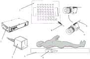
图1是本发明实施例的增强现实手术导航标定装置示意图。FIG. 1 is a schematic diagram of an augmented reality surgical navigation and calibration device according to an embodiment of the present invention.
图2是本发明实施例的标定示意图。FIG. 2 is a schematic diagram of calibration according to an embodiment of the present invention.
具体实施方式Detailed ways
通过下面结合具体实施例及附图,对本发明做进一步说明,但不应以此限制本发明的保护范围。The present invention will be further described below with reference to specific embodiments and accompanying drawings, but the protection scope of the present invention should not be limited by this.
如图1所示,为了进行系统标定,所使用的部件包括电磁定位仪1,磁场发射器2,嵌在手术台3内的对象位置传感器4,单目相机5,相机位置传感器6,标定板7以及标定传感器8。对象位置传感器4与实验者相对位置固定,用于确定实验者在电磁空间下的具体位置。相机位置传感器6固定在单目相机5上方,用于追踪相机的具体位置。标定板7由网格状的50个圆形凹槽构成,各凹槽间的相对位置关系在加工制作时已经确定,再由标定传感器8置入各凹槽中获取各凹槽中心在电磁空间下的坐标。As shown in Figure 1, in order to perform system calibration, the components used include an
如图2所示,标定时主要有两个重要流程,一是通过标定求解对象位置传感器到相机位置传感器的坐标变换关系;二是利用标定板求取相机屏幕与相机位置传感器的坐标变换关系。其中,Sw(xw,yw,zw)为磁场发射器构建的世界坐标系,So(xo,yo,zo)为对象位置传感器建立的对象坐标系,Sc(xc,yc,zc)为相机位置传感器建立的相机坐标系,St(xt,yt,zt)为标定传感器依次置入标定板凹槽构建的标定坐标系,Sd(xd,yd,zd)为相机屏幕坐标系。As shown in Figure 2, there are two important processes during calibration, one is to solve the coordinate transformation relationship between the object position sensor and the camera position sensor through calibration; the other is to use the calibration board to obtain the coordinate transformation relationship between the camera screen and the camera position sensor. Among them, Sw (xw , yw , zw ) is the world coordinate system constructed by the magnetic field transmitter, So (xo , yo , zo ) is the object coordinate system established by the object position sensor, Sc (xc , yc , zc ) is the camera coordinate system established by the camera position sensor, St (xt , yt , zt ) is the calibration coordinate system constructed by placing the calibration sensor into the groove of the calibration plate in turn, Sd (xd , yd , zd ) is the camera screen coordinate system.
开始标定时,设电磁传感器电磁导航仪输出对象位置传感器在世界坐标系Sw下的坐标为pw(tx,ty,tz),与X,Y,Z三轴的夹角分别为θx,θy,θz。平移向量Tow为对象位置传感器在世界坐标系下的三个方向的平移量,写成向量形式为Tow=[tx ty tz]T。对象位置传感器与Z轴正方向的夹角为θz,则绕Z轴旋转的旋转矩阵Row_z为When starting the calibration, let the coordinates of the electromagnetic sensor electromagnetic navigator output object position sensor in the world coordinate system Sw be pw (tx , tyy , tz ), and the angles between the three axes of X, Y, and Z are respectively θx , θy , θz . The translation vector Tow is the translation amount of the object position sensor in the three directions in the world coordinate system, which is written in the vector form as Tow =[txy tz ]T . The angle between the object position sensor and the positive direction of the Z axis is θz , then the rotation matrix Row_z around the Z axis is

对象位置传感器与Y轴正方向的夹角为θy,则绕Y轴旋转的旋转矩阵Row_y为The angle between the object position sensor and the positive direction of the Y-axis is θy , then the rotation matrix Row_y rotating around the Y-axis is

对象位置传感器与X轴正方向的夹角为θx,则绕X轴旋转的旋转矩阵Row_x为The angle between the object position sensor and the positive direction of the X axis is θx , then the rotation matrix Row_x rotating around the X axis is

最后,求得旋转矩阵Row=Row_z·Row_y·Row_x。同理,相机位置传感器的旋转矩阵Rcw与平移向量Tcw求解方式与上述过程相同。结合上述的两对坐标变换关系,最终确定对象位置传感器至相机位置传感器的坐标变换关系:
在第二个流程中,首先利用标定传感器作为探针获取标定板的各点坐标,而后构建标定板的坐标系St(xt,yt,zt),采用四元数法或矩阵伪逆法,求取相机坐标系到标定板坐标系的旋转矩阵Rct和平移向量Tct。接着利用相机从不同角度拍摄多幅标定板图像,由于标定板各凹槽中心的相对位置是已知的,因此根据标定板各点坐标与屏幕中标定板各点的图像坐标,同样使用四元数法或矩阵伪逆法,可得标定板坐标系St(xt,yt,zt)到相机屏幕坐标系Sd(xd,yd,zd)的旋转矩阵Rtd和平移向量Ttd;最终确定相机位置传感器与相机屏幕之间的坐标变换关系:pd=Rtd(Rctpc+Tct)+Ttd,式中,pc为相机坐标系Sc下相机位置传感器的坐标,pd为屏幕坐标系Sd下相机屏幕的坐标。In the second process, first use the calibration sensor as a probe to obtain the coordinates of each point of the calibration plate, and then construct the coordinate system St (xt , yt , zt ) of the calibration plate, using the quaternion method or matrix pseudo In the inverse method, the rotation matrix Rct and the translation vector Tct from the camera coordinate system to the calibration plate coordinate system are obtained. Then use the camera to take multiple images of the calibration board from different angles. Since the relative positions of the centers of the grooves of the calibration board are known, according to the coordinates of each point of the calibration board and the image coordinates of each point of the calibration board on the screen, the same quaternion is used. The number method or the matrix pseudo-inverse method can obtain the rotation matrix Rtd and translation from the calibration board coordinate system St (xt , yt , zt ) to the camera screen coordinate system Sd (xd , yd , zd ) Vector Ttd ; finally determine the coordinate transformation relationship between the camera position sensor and the camera screen: pd =Rtd (Rct pc +Tct )+Ttd , where pc is the camera in the camera coordinate system Sc The coordinates of the position sensor, pd is the coordinates of the camera screen in the screen coordinate system Sd .
综合以上的变换可得到对象位置坐标系So与屏幕坐标系Sd的坐标变换关系:
以上所述实施例只为本发明较佳的实施方式,但本发明的实施方式并不受所述实施案例的限制,其他的任何未背离本发明的精神实质与原理下所作的改变、修饰、替代、组合、简化,均应为等效的置换方式,都包含在本发明的保护范围之内。The above-mentioned embodiments are only preferred embodiments of the present invention, but the embodiments of the present invention are not limited by the examples described above, and any other changes, modifications, Substitution, combination, and simplification should all be equivalent substitution methods, which are all included in the protection scope of the present invention.
Claims (2)
Translated fromChinese


Priority Applications (1)
| Application Number | Priority Date | Filing Date | Title |
|---|---|---|---|
| CN201811500979.3ACN109620408B (en) | 2018-12-10 | 2018-12-10 | Augmented reality operation navigation system calibration method based on electromagnetic positioning |
Applications Claiming Priority (1)
| Application Number | Priority Date | Filing Date | Title |
|---|---|---|---|
| CN201811500979.3ACN109620408B (en) | 2018-12-10 | 2018-12-10 | Augmented reality operation navigation system calibration method based on electromagnetic positioning |
Publications (2)
| Publication Number | Publication Date |
|---|---|
| CN109620408A CN109620408A (en) | 2019-04-16 |
| CN109620408Btrue CN109620408B (en) | 2020-06-19 |
Family
ID=66072416
Family Applications (1)
| Application Number | Title | Priority Date | Filing Date |
|---|---|---|---|
| CN201811500979.3AActiveCN109620408B (en) | 2018-12-10 | 2018-12-10 | Augmented reality operation navigation system calibration method based on electromagnetic positioning |
Country Status (1)
| Country | Link |
|---|---|
| CN (1) | CN109620408B (en) |
Families Citing this family (7)
| Publication number | Priority date | Publication date | Assignee | Title |
|---|---|---|---|---|
| CN110448359B (en)* | 2019-08-02 | 2021-05-14 | 中国人民解放军总医院 | Operation navigation equipment for improving success rate of transjugular intrahepatic portosystemic shunt and application thereof |
| CN110537983B (en)* | 2019-09-26 | 2021-05-14 | 重庆博仕康科技有限公司 | Photo-magnetic integrated puncture surgery navigation platform |
| CA3121670A1 (en) | 2020-06-12 | 2021-12-12 | Ascension Technology Corporation | Distortion correction for electromagnetic fields using inside-out tracking |
| CN112489135B (en)* | 2020-11-27 | 2024-04-19 | 深圳市深图医学影像设备有限公司 | Calibration method of virtual three-dimensional face reconstruction system |
| CN113367795A (en)* | 2021-05-31 | 2021-09-10 | 浙江大学 | Ureteroscope soft lens with magnetic positioning function and ureteroscope pose estimation system |
| CN114159163B (en)* | 2021-12-13 | 2022-09-16 | 南开大学 | Magnetic Navigation System for Soft Mirror |
| CN115153835B (en)* | 2022-07-22 | 2025-01-14 | 华南理工大学 | Feature point registration and augmented reality-based acetabular prosthesis placement guiding system and method |
Citations (5)
| Publication number | Priority date | Publication date | Assignee | Title |
|---|---|---|---|---|
| CN101049248A (en)* | 2007-05-18 | 2007-10-10 | 西安工业大学 | Optical, magnetic, electric composite navigational surgery positioning device and method |
| CN105919669A (en)* | 2016-07-01 | 2016-09-07 | 华南理工大学 | Method for achieving optical surgical navigation surgical instrument calibration through calibrating device |
| WO2017055976A1 (en)* | 2015-10-02 | 2017-04-06 | Koninklijke Philips N.V. | Electromagnetic navigation device for guiding and tracking an interventional tool |
| CN108324373A (en)* | 2018-03-19 | 2018-07-27 | 南开大学 | A kind of puncturing operation robot based on electromagnetic positioning system is accurately positioned implementation method |
| CN108420529A (en)* | 2018-03-26 | 2018-08-21 | 上海交通大学 | The surgical navigational emulation mode guided based on image in magnetic tracking and art |
Family Cites Families (6)
| Publication number | Priority date | Publication date | Assignee | Title |
|---|---|---|---|---|
| DE19817039A1 (en)* | 1998-04-17 | 1999-10-21 | Philips Patentverwaltung | Arrangement for image guided surgery |
| US6774624B2 (en)* | 2002-03-27 | 2004-08-10 | Ge Medical Systems Global Technology Company, Llc | Magnetic tracking system |
| CN2587369Y (en)* | 2002-08-15 | 2003-11-26 | 刘道平 | Electromagnetic operation navigation apparatus based on C type X-ray unit |
| US20040199072A1 (en)* | 2003-04-01 | 2004-10-07 | Stacy Sprouse | Integrated electromagnetic navigation and patient positioning device |
| CN100496429C (en)* | 2005-02-06 | 2009-06-10 | 天津市华志计算机应用有限公司 | Robot operation locating method of surgical operation navigation system based on optical positioning |
| US9326702B2 (en)* | 2013-03-15 | 2016-05-03 | Mediguide Ltd. | Medical device navigation system |
- 2018
- 2018-12-10CNCN201811500979.3Apatent/CN109620408B/enactiveActive
Patent Citations (5)
| Publication number | Priority date | Publication date | Assignee | Title |
|---|---|---|---|---|
| CN101049248A (en)* | 2007-05-18 | 2007-10-10 | 西安工业大学 | Optical, magnetic, electric composite navigational surgery positioning device and method |
| WO2017055976A1 (en)* | 2015-10-02 | 2017-04-06 | Koninklijke Philips N.V. | Electromagnetic navigation device for guiding and tracking an interventional tool |
| CN105919669A (en)* | 2016-07-01 | 2016-09-07 | 华南理工大学 | Method for achieving optical surgical navigation surgical instrument calibration through calibrating device |
| CN108324373A (en)* | 2018-03-19 | 2018-07-27 | 南开大学 | A kind of puncturing operation robot based on electromagnetic positioning system is accurately positioned implementation method |
| CN108420529A (en)* | 2018-03-26 | 2018-08-21 | 上海交通大学 | The surgical navigational emulation mode guided based on image in magnetic tracking and art |
Also Published As
| Publication number | Publication date |
|---|---|
| CN109620408A (en) | 2019-04-16 |
Similar Documents
| Publication | Publication Date | Title |
|---|---|---|
| CN109620408B (en) | Augmented reality operation navigation system calibration method based on electromagnetic positioning | |
| Martin-Gomez et al. | Sttar: surgical tool tracking using off-the-shelf augmented reality head-mounted displays | |
| CA3034314C (en) | Methods and systems for registration of virtual space with real space in an augmented reality system | |
| Wang et al. | Augmented reality navigation with automatic marker-free image registration using 3-D image overlay for dental surgery | |
| US7774044B2 (en) | System and method for augmented reality navigation in a medical intervention procedure | |
| CN111281540B (en) | Real-time visualization navigation system for minimally invasive orthopaedic surgery based on virtual-real fusion | |
| CN106308946B (en) | A kind of augmented reality devices and methods therefor applied to stereotactic surgery robot | |
| CN103211655B (en) | A kind of orthopaedics operation navigation system and air navigation aid | |
| CN101904770B (en) | Operation guiding system and method based on optical enhancement reality technology | |
| CN105395252A (en) | Wearable 3D image navigation device for vascular interventional surgery with human-computer interaction | |
| CN113143463B (en) | Operation navigation device, system, calibration method, medium and electronic equipment | |
| TWI697317B (en) | Digital image reality alignment kit and method applied to mixed reality system for surgical navigation | |
| CN101099673A (en) | Surgical instrument positioning method using infrared reflective ball as marker point | |
| CN103948432A (en) | Algorithm for augmented reality of three-dimensional endoscopic video and ultrasound image during operation | |
| CN111035458A (en) | Intelligent auxiliary system for operation comprehensive vision and image processing method | |
| Wang et al. | The Kinect as an interventional tracking system | |
| WO2023065495A1 (en) | Intracranial hematoma puncture and drainage operation system using robotic arm for puncture | |
| CN115500940A (en) | Surgical needle positioning display method and related device | |
| CN114937139A (en) | Endoscope augmented reality system and method based on video stream fusion | |
| CN117918955B (en) | Augmented reality surgical navigation device, method, system equipment and medium | |
| US20030179249A1 (en) | User interface for three-dimensional data sets | |
| Thoranaghatte et al. | Landmark‐based augmented reality system for paranasal and transnasal endoscopic surgeries | |
| Wengert et al. | Endoscopic navigation for minimally invasive suturing | |
| JP2022047374A (en) | Surgical navigation system, medical imaging system with surgical navigation function, and registration method of medical images for surgical navigation | |
| CN115245302A (en) | System and method for reconstructing three-dimensional scene based on endoscope image |
Legal Events
| Date | Code | Title | Description |
|---|---|---|---|
| PB01 | Publication | ||
| PB01 | Publication | ||
| SE01 | Entry into force of request for substantive examination | ||
| SE01 | Entry into force of request for substantive examination | ||
| GR01 | Patent grant | ||
| GR01 | Patent grant |