CN109617834B - A precise load shedding system and its communication method and access device - Google Patents
A precise load shedding system and its communication method and access deviceDownload PDFInfo
- Publication number
- CN109617834B CN109617834BCN201910104886.7ACN201910104886ACN109617834BCN 109617834 BCN109617834 BCN 109617834BCN 201910104886 ACN201910104886 ACN 201910104886ACN 109617834 BCN109617834 BCN 109617834B
- Authority
- CN
- China
- Prior art keywords
- control
- optical fiber
- data
- access device
- frames
- Prior art date
- Legal status (The legal status is an assumption and is not a legal conclusion. Google has not performed a legal analysis and makes no representation as to the accuracy of the status listed.)
- Active
Links
Images

Classifications
- H—ELECTRICITY
- H04—ELECTRIC COMMUNICATION TECHNIQUE
- H04L—TRANSMISSION OF DIGITAL INFORMATION, e.g. TELEGRAPHIC COMMUNICATION
- H04L47/00—Traffic control in data switching networks
- H04L47/70—Admission control; Resource allocation
- H04L47/78—Architectures of resource allocation
- H—ELECTRICITY
- H04—ELECTRIC COMMUNICATION TECHNIQUE
- H04L—TRANSMISSION OF DIGITAL INFORMATION, e.g. TELEGRAPHIC COMMUNICATION
- H04L49/00—Packet switching elements
- H04L49/55—Prevention, detection or correction of errors
- H—ELECTRICITY
- H04—ELECTRIC COMMUNICATION TECHNIQUE
- H04L—TRANSMISSION OF DIGITAL INFORMATION, e.g. TELEGRAPHIC COMMUNICATION
- H04L12/00—Data switching networks
- H04L12/02—Details
- H04L12/10—Current supply arrangements
- H—ELECTRICITY
- H02—GENERATION; CONVERSION OR DISTRIBUTION OF ELECTRIC POWER
- H02J—CIRCUIT ARRANGEMENTS OR SYSTEMS FOR SUPPLYING OR DISTRIBUTING ELECTRIC POWER; SYSTEMS FOR STORING ELECTRIC ENERGY
- H02J13/00—Circuit arrangements for providing remote indication of network conditions, e.g. an instantaneous record of the open or closed condition of each circuitbreaker in the network; Circuit arrangements for providing remote control of switching means in a power distribution network, e.g. switching in and out of current consumers by using a pulse code signal carried by the network
- H02J13/00006—Circuit arrangements for providing remote indication of network conditions, e.g. an instantaneous record of the open or closed condition of each circuitbreaker in the network; Circuit arrangements for providing remote control of switching means in a power distribution network, e.g. switching in and out of current consumers by using a pulse code signal carried by the network characterised by information or instructions transport means between the monitoring, controlling or managing units and monitored, controlled or operated power network element or electrical equipment
- H02J13/00019—Circuit arrangements for providing remote indication of network conditions, e.g. an instantaneous record of the open or closed condition of each circuitbreaker in the network; Circuit arrangements for providing remote control of switching means in a power distribution network, e.g. switching in and out of current consumers by using a pulse code signal carried by the network characterised by information or instructions transport means between the monitoring, controlling or managing units and monitored, controlled or operated power network element or electrical equipment using optical means
- H—ELECTRICITY
- H02—GENERATION; CONVERSION OR DISTRIBUTION OF ELECTRIC POWER
- H02J—CIRCUIT ARRANGEMENTS OR SYSTEMS FOR SUPPLYING OR DISTRIBUTING ELECTRIC POWER; SYSTEMS FOR STORING ELECTRIC ENERGY
- H02J3/00—Circuit arrangements for AC mains or AC distribution networks
- H02J3/12—Circuit arrangements for AC mains or AC distribution networks for adjusting voltage in AC networks by changing a characteristic of the network load
- H02J3/14—Circuit arrangements for AC mains or AC distribution networks for adjusting voltage in AC networks by changing a characteristic of the network load by switching loads on to, or off from, network, e.g. progressively balanced loading
- H—ELECTRICITY
- H04—ELECTRIC COMMUNICATION TECHNIQUE
- H04L—TRANSMISSION OF DIGITAL INFORMATION, e.g. TELEGRAPHIC COMMUNICATION
- H04L1/00—Arrangements for detecting or preventing errors in the information received
- H04L1/004—Arrangements for detecting or preventing errors in the information received by using forward error control
- Y—GENERAL TAGGING OF NEW TECHNOLOGICAL DEVELOPMENTS; GENERAL TAGGING OF CROSS-SECTIONAL TECHNOLOGIES SPANNING OVER SEVERAL SECTIONS OF THE IPC; TECHNICAL SUBJECTS COVERED BY FORMER USPC CROSS-REFERENCE ART COLLECTIONS [XRACs] AND DIGESTS
- Y02—TECHNOLOGIES OR APPLICATIONS FOR MITIGATION OR ADAPTATION AGAINST CLIMATE CHANGE
- Y02B—CLIMATE CHANGE MITIGATION TECHNOLOGIES RELATED TO BUILDINGS, e.g. HOUSING, HOUSE APPLIANCES OR RELATED END-USER APPLICATIONS
- Y02B70/00—Technologies for an efficient end-user side electric power management and consumption
- Y02B70/30—Systems integrating technologies related to power network operation and communication or information technologies for improving the carbon footprint of the management of residential or tertiary loads, i.e. smart grids as climate change mitigation technology in the buildings sector, including also the last stages of power distribution and the control, monitoring or operating management systems at local level
- Y02B70/3225—Demand response systems, e.g. load shedding, peak shaving
- Y—GENERAL TAGGING OF NEW TECHNOLOGICAL DEVELOPMENTS; GENERAL TAGGING OF CROSS-SECTIONAL TECHNOLOGIES SPANNING OVER SEVERAL SECTIONS OF THE IPC; TECHNICAL SUBJECTS COVERED BY FORMER USPC CROSS-REFERENCE ART COLLECTIONS [XRACs] AND DIGESTS
- Y04—INFORMATION OR COMMUNICATION TECHNOLOGIES HAVING AN IMPACT ON OTHER TECHNOLOGY AREAS
- Y04S—SYSTEMS INTEGRATING TECHNOLOGIES RELATED TO POWER NETWORK OPERATION, COMMUNICATION OR INFORMATION TECHNOLOGIES FOR IMPROVING THE ELECTRICAL POWER GENERATION, TRANSMISSION, DISTRIBUTION, MANAGEMENT OR USAGE, i.e. SMART GRIDS
- Y04S20/00—Management or operation of end-user stationary applications or the last stages of power distribution; Controlling, monitoring or operating thereof
- Y04S20/20—End-user application control systems
- Y04S20/222—Demand response systems, e.g. load shedding, peak shaving
Landscapes
- Engineering & Computer Science (AREA)
- Computer Networks & Wireless Communication (AREA)
- Signal Processing (AREA)
- Power Engineering (AREA)
- Small-Scale Networks (AREA)
- Selective Calling Equipment (AREA)
- Remote Monitoring And Control Of Power-Distribution Networks (AREA)
Abstract
Translated fromChinese
Description
Translated fromChinese技术领域technical field
本发明实施例涉及电力系统技术领域,尤其涉及一种精准切负荷系统及其通信方法、接入装置。Embodiments of the present invention relate to the technical field of power systems, and in particular, to a precise load shedding system, a communication method, and an access device thereof.
背景技术Background technique
常规的安全稳定控制系统中一个控制终端就要占用一个2M通道,当接入的控制终端数量较多时,若每个控制终端都独占一个2M通道,则需占用大量的通信带宽,不利于节省投资。In a conventional security and stability control system, one control terminal occupies a 2M channel. When the number of access control terminals is large, if each control terminal occupies a 2M channel exclusively, it will take up a lot of communication bandwidth, which is not conducive to saving investment. .
精准切负荷系统能够将分散性的电力用户可中断负荷集中起来进行毫秒级精准控制,实施灵活调节,达到电力供需瞬时平衡。现有的精准切负荷系统通常可以分为三层,即控制主站层、控制子站层和终端用户接入层。然而,现有的精准切负荷系统中并没有具体能够实现控制子站层和终端用户接入层数据交互的接入装置,对于精准切负荷系统的可靠性也没有涉及。The precise load shedding system can centralize the interruptible loads of distributed power users for millisecond-level precise control, implement flexible adjustment, and achieve an instantaneous balance of power supply and demand. The existing precise load shedding system can usually be divided into three layers, namely the control master station layer, the control substation layer and the end user access layer. However, in the existing precise load shedding system, there is no specific access device capable of realizing data interaction between the substation layer and the terminal user access layer, and the reliability of the precise load shedding system is not involved.
发明内容SUMMARY OF THE INVENTION
本发明提供一种精准切负荷系统及其通信方法、接入装置,能够在解决常规的安全稳定控制系统方案通信带宽占用过多的问题的同时,提高可靠性,节约投资成本,并降低维护难度。The present invention provides a precise load shedding system, a communication method and an access device thereof, which can improve reliability, save investment cost, and reduce maintenance difficulty while solving the problem of too much communication bandwidth occupied by conventional security and stability control system solutions. .
第一方面,本发明实施例提供了一种接入装置,包括:两路E1接口、八路光纤接口、中央处理器CPU和现场可编程逻辑门阵列FPGA;其中,In a first aspect, an embodiment of the present invention provides an access device, including: two E1 interfaces, eight optical fiber interfaces, a central processing unit (CPU), and a field programmable logic gate array (FPGA); wherein,
两路E1接口分别与控制子站的A套控制装置和B套控制装置连接;The two E1 interfaces are respectively connected to the A control device and the B control device of the control substation;
八路光纤接口分别与八个控制终端连接;Eight optical fiber interfaces are respectively connected with eight control terminals;
FPGA包括八组光纤收发模块和两组E1收发模块,八组光纤收发模块分别通过串行接口与八路光纤接口连接,两组E1收发模块分别通过串行接口与两路E1接口连接,每组光纤收发模块中均设置有复位子模块,每组E1收发模块中均设置有复位子模块;The FPGA includes eight groups of optical fiber transceiver modules and two groups of E1 transceiver modules. The eight groups of optical fiber transceiver modules are respectively connected to eight-way optical fiber interfaces through serial interfaces, and the two sets of E1 transceiver modules are respectively connected to two-way E1 interfaces through serial interfaces. A reset sub-module is set in the transceiver module, and a reset sub-module is set in each group of E1 transceiver modules;
CPU通过并行总线与FPGA连接。The CPU is connected to the FPGA through a parallel bus.
可选的,FPGA还包括与CPU连接的看门狗模块;Optionally, the FPGA also includes a watchdog module connected to the CPU;
看门狗模块,用于在确认CPU故障后,复位接入装置;The watchdog module is used to reset the access device after confirming the CPU failure;
CPU,用于在确认FPGA故障后,且复位次数小于或者等于3,复位接入装置。The CPU is used to reset the access device after confirming that the FPGA is faulty and the number of resets is less than or equal to 3.
可选的,光纤收发模块的物理层采用8b10b的编码方式,通讯速率为32.768Mbits/s;Optionally, the physical layer of the optical fiber transceiver module adopts the 8b10b encoding method, and the communication rate is 32.768Mbits/s;
E1收发模块的物理层符合ITU-T G.703规范,通讯速率为2Mbits/s,误码率小于10-8。The physical layer of the E1 transceiver module conforms to the ITU-T G.703 specification, the communication rate is 2Mbits/s, and the bit error rate is less than10-8 .
可选的,复位子模块,用于在确认复位子模块对应的E1收发模块或者光纤收发模块故障后,单独复位该复位子模块对应的E1收发模块或者光纤收发模块。Optionally, the reset submodule is used to independently reset the E1 transceiver module or the optical fiber transceiver module corresponding to the reset submodule after confirming that the E1 transceiver module or the optical fiber transceiver module corresponding to the reset submodule is faulty.
第二方面,本发明实施例还提供了一种精准切负荷系统,包括:具有如本发明实施例第一方面任一的接入装置、控制子站,以及至少一个控制终端。In a second aspect, an embodiment of the present invention further provides a precise load shedding system, including: the access device according to any one of the first aspect of the embodiment of the present invention, a control sub-station, and at least one control terminal.
第三方面,本发明实施例还提供了一种精准切负荷系统的通信方法,方法适用于具有如本发明实施例第二方面的精准切负荷系统,方法包括:In a third aspect, an embodiment of the present invention further provides a communication method for a precise load shedding system, the method is applicable to the precise load shedding system according to the second aspect of the embodiment of the present invention, and the method includes:
接收控制子站发送的下行数据;Receive downlink data sent by the control sub-station;
采用复用算法对下行数据进行处理;Use multiplexing algorithm to process downlink data;
向控制终端发送处理后的下行数据;Send the processed downlink data to the control terminal;
其中,下行数据为两帧数据帧或者两帧命令帧,处理后的下行数据为两帧数据帧或者两帧命令帧,两帧数据帧或者两帧命令帧分别对应控制子站的A套控制装置和B套控制装置。Among them, the downlink data is two frames of data frames or two frames of command frames, the processed downlink data is two frames of data frames or two frames of command frames, and the two frames of data frames or two frames of command frames respectively correspond to the control device A set of the control substation and B sets of control devices.
可选的,还包括:Optionally, also include:
接收控制终端发送的上行数据;Receive the uplink data sent by the control terminal;
采用复用算法对上行数据进行处理;Use multiplexing algorithm to process uplink data;
向控制子站发送处理后的上行数据;Send the processed uplink data to the control substation;
其中,上行数据和处理后的上行数据为一帧数据帧。The uplink data and the processed uplink data are one data frame.
可选的,命令帧的长度为12个字,每个字包括16个bit;命令帧包括:长度为1个字的帧头、长度为8个字的控制命令、长度为1个字的总体信息、长度为1个字的发送序号和长度为1个字的循环冗余校验CRC校验码,控制命令中包括正码和反码。Optionally, the length of the command frame is 12 words, and each word includes 16 bits; the command frame includes: a frame header with a length of 1 word, a control command with a length of 8 words, and an overall length of 1 word. The information, the sending sequence number with a length of 1 word, and the CRC check code with a length of 1 word, the control command includes a positive code and a negative code.
可选的,数据帧的长度为12个字,每个字包括16个bit;数据帧包括:长度为1个字的帧头、长度为8个字的数据信息、长度为1个字的总体信息、长度为1个字的发送序号和长度为1个字的CRC校验码。Optionally, the length of the data frame is 12 words, and each word includes 16 bits; the data frame includes: a frame header with a length of 1 word, data information with a length of 8 words, and an overall length of 1 word. information, the transmission sequence number with a length of 1 word, and the CRC check code with a length of 1 word.
第四方面,本发明实施例还提供了一种计算机可读存储介质,其上存储有计算机程序,该计算机程序被处理器执行时实现如本发明实施例第三方面任一的精准切负荷系统的通信方法。In a fourth aspect, an embodiment of the present invention further provides a computer-readable storage medium on which a computer program is stored, and when the computer program is executed by a processor, implements the precise load shedding system according to any one of the third aspect of the embodiment of the present invention communication method.
本发明提供的接入装置包括:两路E1接口、八路光纤接口、中央处理器CPU和现场可编程逻辑门阵列FPGA;其中,两路E1接口分别与控制子站的A套控制装置和B套控制装置连接;八路光纤接口分别与八个控制终端连接;FPGA包括八组光纤收发模块和两组E1收发模块,八组光纤收发模块分别通过串行接口与八路光纤接口连接,两组E1收发模块分别通过串行接口与两路E1接口连接,每组光纤收发模块中均设置有复位子模块,每组E1收发模块中均设置有复位子模块;CPU通过并行总线与FPGA连接。由于接入装置能够在通过FPGA、两路E1接口和八路光纤接口实现数据的收发,适用于实际工程,同时FPGA的每组光纤收发模块中均设置有复位子模块、每组E1收发模块中均设置有复位子模块,提升了接入装置的可靠性,因此能够在解决常规的安全稳定控制系统方案通信带宽占用过多的问题的同时,节约投资成本,并降低维护难度。The access device provided by the present invention includes: two-way E1 interface, eight-way optical fiber interface, central processing unit CPU and field programmable logic gate array FPGA; wherein, the two-way E1 interface is respectively connected with the A set of control devices and the B set of control substations. The control device is connected; the eight optical fiber interfaces are respectively connected with eight control terminals; the FPGA includes eight groups of optical fiber transceiver modules and two groups of E1 transceiver modules, the eight groups of optical fiber transceiver modules are respectively connected with the eight optical fiber interfaces through serial interfaces, and two groups of E1 transceiver modules are connected They are respectively connected with two E1 interfaces through serial interfaces, reset sub-modules are set in each group of optical fiber transceiver modules, and reset sub-modules are set in each group of E1 transceiver modules; CPU is connected with FPGA through parallel bus. Since the access device can transmit and receive data through the FPGA, two E1 interfaces and eight optical fiber interfaces, it is suitable for practical projects. At the same time, each group of optical fiber transceiver modules in the FPGA is provided with a reset sub-module, and each group of E1 transceiver modules is provided with a reset sub-module. The reset sub-module is provided, which improves the reliability of the access device, so it can save the investment cost and reduce the maintenance difficulty while solving the problem that the communication bandwidth is occupied by the conventional security and stability control system solution.
附图说明Description of drawings
图1是本发明实施例提供的一种精准切负荷系统的结构示意图;1 is a schematic structural diagram of a precise load shedding system provided by an embodiment of the present invention;
图2是本发明实施例提供的一种接入装置的结构示意图;FIG. 2 is a schematic structural diagram of an access device provided by an embodiment of the present invention;
图3是本发明实施例提供的一种精准切负荷系统的通信方法的流程示意图。FIG. 3 is a schematic flowchart of a communication method of a precise load shedding system according to an embodiment of the present invention.
具体实施方式Detailed ways
下面结合附图和实施例对本发明作进一步的详细说明。可以理解的是,此处所描述的具体实施例仅仅用于解释本发明,而非对本发明的限定。另外还需要说明的是,为了便于描述,附图中仅示出了与本发明相关的部分而非全部结构。The present invention will be further described in detail below in conjunction with the accompanying drawings and embodiments. It should be understood that the specific embodiments described herein are only used to explain the present invention, but not to limit the present invention. In addition, it should be noted that, for the convenience of description, the drawings only show some but not all structures related to the present invention.
需要说明的是,本公开中术语“系统”和“网络”在本文中常被可互换使用。本发明实施例中提到的“和/或”是指包括一个或更多个相关所列项目的任何和所有组合。本发明的说明书和权利要求书及附图中的术语“第一”、“第二”等是用于区别不同对象,而不是用于限定特定顺序。It should be noted that in this disclosure, the terms "system" and "network" are often used interchangeably herein. References to "and/or" in the embodiments of the present invention are meant to include any and all combinations of one or more of the associated listed items. The terms "first", "second" and the like in the description and claims of the present invention and the drawings are used to distinguish different objects, rather than to limit a specific order.
还需要说明是,本发明下述各个实施例可以单独执行,各个实施例之间也可以相互结合执行,本发明实施例对此不作具体限制。It should also be noted that each of the following embodiments of the present invention may be implemented independently, or may be implemented in combination with each other, which is not specifically limited in this embodiment of the present invention.
下面,对精准切负荷系统、通信方法、接入装置及其技术效果进行详细描述。Below, the precise load shedding system, communication method, access device and technical effects thereof will be described in detail.
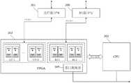
图1为本发明实施例提供的一种精准切负荷系统的结构示意图,包括:控制主站层、控制子站层和终端用户接入层。FIG. 1 is a schematic structural diagram of a precise load shedding system provided by an embodiment of the present invention, including: a control master station layer, a control substation layer, and an end user access layer.
控制主站层包括控制主站10,控制主站10分为A套控制装置和B套控制装置。控制主站10通常为设在直流落点换流站近区通道条件好的500kV交流汇集站,控制主站10可以接收上级稳控系统发送的切负荷指令,并进行负荷分配,下发切负荷指令。The control master station layer includes a
控制子站层包括控制子站20,控制子站20分为A套控制装置和B套控制装置。控制子站20和控制主站10通过SDH 2M线路连接。控制子站20通常为设在负荷集中区域的500kV交流站和/或220kV交流站。控制子站20可以收集本地区可切负荷量信息,并将可切负荷量信息发送至控制主站10,并执行控制主站装置发送的切负荷指令。The control sub-station layer includes a
终端用户接入层包括接入装置30和至少一个控制终端31。接入装置30与控制子站20通过同步数字体系(Synchronous Digital Hierarchy,SDH)设备连接,每个接入装置最多可以与八个控制终端31连接。The end user access layer includes an
图2为本发明实施例提供的一种接入装置的结构示意图,包括:两路E1接口300、八路光纤接口301、中央处理器(Central Processing Unit,CPU)302和现场可编程逻辑门阵列(Field Programmable Gate Array,FPGA)303。2 is a schematic structural diagram of an access device according to an embodiment of the present invention, including: two
两路E1接口300分别与控制子站20的A套控制装置和B套控制装置通过E1通道连接;The two
八路光纤接口301分别与八个控制终端31通过专用光纤通道连接;The eight
FPGA 303包括八组光纤收发模块(图2中分别以光纤-1、光纤-2、…、光纤-8标示)和两组E1收发模块(图2中分别以E1-1和E1-2标示),八组光纤收发模块分别通过串行接口与八路光纤接口301连接,两组E1收发模块分别通过串行接口与两路E1接口300连接,每组光纤收发模块中均设置有复位子模块,每组E1收发模块中均设置有复位子模块;复位子模块用于在确认复位子模块对应的E1收发模块或者光纤收发模块故障后,单独复位该复位子模块对应的E1收发模块或者光纤收发模块。由于复位子模块独立存在,能够被CPU控制用以实现模块的单独复位,不影响其他通信链路,从而解决由于FPGA受到干扰而导致的某个通信链路中断问题,提高了可靠性;The
CPU 302通过并行总线与FPGA 303连接,同时写入需要发送的数据并控制发送。The
接入装置30可以接收控制子站20的A套控制装置和B套控制装置发送的下行数据,并转发下行数据至接入该接入装置30的所有控制终端31;接入装置30还可以接收接入该接入装置30的所有控制终端31发送的上行数据,并转发上行数据至控制子站20的A套控制装置和B套控制装置。其中,下行数据可以为数据帧和/或命令帧;上行数据可以为数据帧。The
具体的,接入装置30接收控制子站20的A套控制装置和B套控制装置发送的下行数据,并转发下行数据至接入该接入装置30的所有控制终端31的工作过程为:接入装置30的两路E1接口300接收控制子站20的A套控制装置和B套控制装置发送的下行数据,FPGA 303中的两组E1收发模块读取该下行数据,并将下行数据发送至CPU 302进行处理,得到对应光纤通道的数据后反馈给FPGA 303,FPGA 303中的八组光纤收发模块通过八路光纤接口301将该下行数据发送至接入该接入装置30的所有控制终端31。Specifically, the working process of the
接入装置30接收接入该接入装置30的所有控制终端31发送的上行数据,并转发上行数据至控制子站20的A套控制装置和B套控制装置的工作过程为:接入装置30的八路光纤接口301接收接入该接入装置30的所有控制终端31发送的上行数据,FPGA 303中的八组光纤收发模块读取该上行数据,并将上行数据发送至CPU 302进行处理,得到对应E1通道的数据后反馈给FPGA 303,FPGA 303中的两组E1收发模块通过两路E1接口300将该上行数据至控制子站20的A套控制装置和B套控制装置。The
其中,光纤收发模块的物理层采用8b10b的编码方式,通讯速率为32.768Mbits/s;Among them, the physical layer of the optical fiber transceiver module adopts the 8b10b encoding method, and the communication rate is 32.768Mbits/s;
E1收发模块通过75欧姆同轴电缆不平衡方式与SDH设备通讯,E1收发模块的物理层符合ITU-T G.703规范,通讯速率为2Mbits/s,误码率小于10-8。The E1 transceiver module communicates with the SDH equipment through the unbalanced 75-ohm coaxial cable. The physical layer of the E1 transceiver module conforms to the ITU-T G.703 specification, the communication rate is 2Mbits/s, and the bit error rate is less than10-8 .
另外,FPGA 303与八路光纤接口301通讯的链路层协议为自有协议,与两路E1接口300通讯的链路层协议为高级数据链路控制(High-Level Data Link Control,HDLC)协议。In addition, the link layer protocol used by the
进一步地,如图2所示,FPGA 303还包括与CPU 302连接的看门狗模块305;Further, as shown in FIG. 2 , the
看门狗模块305,用于在确认CPU 302故障后,复位接入装置30。具体的,CPU 302按照固定的周期定时去喂狗,若CPU 302超过预设时间未喂狗,则看门狗模块305确认CPU 302故障,看门狗模块305复位接入装置30,如此,能够有效防止CPU 302受干扰死机或者CPU302访问FPGA 303的总线受干扰导致的通信长时间中断,提高了可靠性。The
CPU 302,用于在确认FPGA 303故障后,且复位次数小于或者等于3,主动复位接入装置30。具体的,以初始状态为例,CPU 302只要曾经收到过两路E1接口300和/或八路光纤接口301发送的任意一路正确数据,后面持续Tnr时间收不到一帧正确的两路E1接口300和/或八路光纤接口301数据,则CPU302确认FPGA 303故障,CPU 302主动复位接入装置30,并在非易失存储器中记录下1次复位次数;复位后还是持续Tnr时间收不到一帧正确的两路E1接口300和/或八路光纤接口301数据,则CPU 302再次主动复位接入装置30,并又在非易失存储器中记录下1次复位次数;若复位后还是持续Tnr时间收不到一帧正确的两路E1接口300和/或八路光纤接口301数据,则再执行一次复位操作并记录复位次数。当记录的复位次数为3,即使后续仍旧持续Tnr时间收不到一帧正确的两路E1接口300和/或八路光纤接口301数据,也不再执行复位操作;如果复位后收到一帧正确的两路E1接口300和/或八路光纤接口301数据,则CPU 302将非易失存储器中记录的复位次数清0。The
本发明实施例提供一种接入装置,包括:两路E1接口、八路光纤接口、中央处理器CPU和现场可编程逻辑门阵列FPGA;其中,两路E1接口分别与控制子站的A套控制装置和B套控制装置连接;八路光纤接口分别与八个控制终端连接;FPGA包括八组光纤收发模块和两组E1收发模块,八组光纤收发模块分别通过串行接口与八路光纤接口连接,两组E1收发模块分别通过串行接口与两路E1接口连接,每组光纤收发模块中均设置有复位子模块,每组E1收发模块中均设置有复位子模块;CPU通过并行总线与FPGA连接。由于接入装置能够在通过FPGA、两路E1接口和八路光纤接口实现数据的收发,适用于实际工程,同时FPGA的每组光纤收发模块中均设置有复位子模块、每组E1收发模块中均设置有复位子模块,提升了接入装置的可靠性,因此能够在解决常规的安全稳定控制系统方案通信带宽占用过多的问题的同时,节约投资成本,并降低维护难度。An embodiment of the present invention provides an access device, including: two E1 interfaces, eight optical fiber interfaces, a central processing unit (CPU), and a field programmable logic gate array (FPGA); wherein, the two E1 interfaces are respectively connected to the control set A of the substation. The device is connected with the B set of control devices; the eight optical fiber interfaces are respectively connected with eight control terminals; the FPGA includes eight groups of optical fiber transceiver modules and two groups of E1 transceiver modules, and the eight groups of optical fiber transceiver modules are respectively connected with the eight optical fiber interfaces through the serial interface, and the two Group E1 transceiver modules are respectively connected with two E1 interfaces through serial interfaces. Each group of optical fiber transceiver modules is provided with a reset sub-module, and each group of E1 transceiver modules is provided with a reset sub-module. The CPU is connected to the FPGA through a parallel bus. Since the access device can transmit and receive data through the FPGA, two E1 interfaces and eight optical fiber interfaces, it is suitable for practical projects. At the same time, each group of optical fiber transceiver modules in the FPGA is provided with a reset sub-module, and each group of E1 transceiver modules is provided with a reset sub-module. The reset sub-module is provided, which improves the reliability of the access device, so it can save the investment cost and reduce the maintenance difficulty while solving the problem that the communication bandwidth is occupied by the conventional security and stability control system solution.
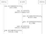
图3为本发明实施例提供的一种精准切负荷系统的通信方法的流程示意图,该方法适用于上述实施例中的精准切负荷系统,如图3所示,方法包括如下步骤:FIG. 3 is a schematic flowchart of a communication method of a precise load shedding system provided by an embodiment of the present invention. The method is applicable to the precise load shedding system in the above-mentioned embodiment. As shown in FIG. 3 , the method includes the following steps:
S101、接入装置接收控制子站发送的下行数据。S101. The access device receives the downlink data sent by the control substation.
下行数据可以为数据帧或者命令帧。其中,数据帧可以为可切负荷量信息、功率信息、状态信息等数据信息,命令帧可以为切负荷指令、恢复符合指令等指令信息。Downlink data can be data frames or command frames. The data frame may be data information such as load shedding amount information, power information, status information, etc., and the command frame may be instruction information such as a load shedding instruction, a recovery compliance instruction, and the like.
S102、接入装置采用复用算法对下行数据进行处理。S102, the access device uses a multiplexing algorithm to process the downlink data.
S103、接入装置向控制终端发送处理后的下行数据。S103: The access device sends the processed downlink data to the control terminal.
当下行数据为数据帧时,处理后的下行数据也为数据帧;当下行数据为命令帧时,处理后的下行数据也为命令帧。When the downlink data is a data frame, the processed downlink data is also a data frame; when the downlink data is a command frame, the processed downlink data is also a command frame.
具体的,接入装置给接入该接入装置的所有控制终端发送处理后的下行数据均是同一时刻发送的。Specifically, the processed downlink data sent by the access device to all control terminals accessing the access device is sent at the same time.
S104、接入装置接收控制终端发送的上行数据。S104. The access device receives the uplink data sent by the control terminal.
上行数据为数据帧。Uplink data is a data frame.
具体的,接入装置接收接入该接入装置的所有控制终端发送的上行数据均是同一时刻接收的。Specifically, the access device receives the uplink data sent by all control terminals accessing the access device at the same time.
S105、接入装置采用复用算法对上行数据进行处理。S105, the access device uses a multiplexing algorithm to process the uplink data.
S106、接入装置向控制子站发送处理后的上行数据。S106: The access device sends the processed uplink data to the control substation.
由于上行数据为数据帧,因此处理后的上行数据也为数据帧。Since the uplink data is a data frame, the processed uplink data is also a data frame.
另外,接入装置将处理后的上行数据按一定的时间间隔Tval轮询送给控制子站的A套控制装置和B套控制装置,在Tval时间间隔内,上送给控制子站的A套控制装置和B套控制装置的数据是同一个光纤接口收到的数据,如此,可以防止通道上偶发的丢一帧现象导致某个控制终端的信息上送不及时的问题,提高了可靠性。In addition, the access device polls the processed uplink data to the A control device and the B control device of the control substation at a certain time interval Tval, and sends it to the A control device of the control substation within the Tval time interval. The data of the control device and the control device of the B set are the data received by the same optical fiber interface. In this way, the occasional loss of a frame on the channel can prevent the problem that the information of a control terminal is not sent in time, and the reliability is improved.
进一步地,表1为下行数据、处理后的下行数据、上行数据和处理后的上行数据的基本信息。Further, Table 1 is the basic information of downlink data, processed downlink data, uplink data and processed uplink data.
表1Table 1


其中,K、L、M、N可根据实际工程需要进行具体约定,但需满足下述原则:Among them, K, L, M, N can be specified according to the actual project needs, but the following principles must be met:

从表1中可以看出,控制子站向接入装置发送下行数据的通信频率为K帧/秒,具体的控制子站的A套控制装置和B套控制装置每次通信时分别各发一帧,每帧的长度为12个字,每个字包括16个bit。接入装置处理后到控制终端的下行数据每次通信时分别各发两帧,即第1帧为控制子站A套控制装置所发信息,第2帧为B套控制装置所发信息。控制终端向接入装置发送的上行数据同理,为了简洁,此处不再赘述。It can be seen from Table 1 that the communication frequency at which the control sub-station sends downlink data to the access device is K frames/sec. Specifically, the A control device and the B control device of the specific control sub-station each send a Frame, the length of each frame is 12 words, and each word includes 16 bits. After the access device processes the downlink data to the control terminal each time it communicates, it sends two frames respectively, that is, the first frame is the information sent by the control device of the control substation A, and the second frame is the information sent by the control device of the B set. The same is true for the uplink data sent by the control terminal to the access device, which is not repeated here for brevity.
同时从表1可以看到,接入装置收发数据的时间间隔固定、且帧长固定,可以有效防止饱和攻击和溢出攻击,提高了可靠性。At the same time, it can be seen from Table 1 that the access device has a fixed time interval for sending and receiving data and a fixed frame length, which can effectively prevent saturation attacks and overflow attacks and improve reliability.
另外,本发明实施例所涉及的数据的发送和接收都采用定时间间隔的方式,间隔时间小于或者等于通信频率的倒数。In addition, the transmission and reception of the data involved in the embodiments of the present invention both adopt the manner of a fixed time interval, and the interval time is less than or equal to the inverse of the communication frequency.
进一步地,本发明实施例还对分别对下行数据、处理后的下行数据、上行数据和处理后的上行数据的帧内容进行了定义。Further, the embodiments of the present invention also define frame contents of downlink data, processed downlink data, uplink data, and processed uplink data, respectively.
其中,表2为控制子站向接入装置发送的下行数据的帧内容。Wherein, Table 2 is the frame content of the downlink data sent by the control substation to the access device.
表2Table 2


表3为接入装置向控制终端发送的处理后的下行数据的帧内容。Table 3 shows the frame content of the processed downlink data sent by the access device to the control terminal.
表3table 3


表4为控制终端向接入装置发送的上行数据的帧内容。Table 4 shows the frame content of the uplink data sent by the control terminal to the access device.
表4Table 4
表5为接入装置向控制子站发送的处理后的上行数据的帧内容。Table 5 shows the frame content of the processed uplink data sent by the access device to the control substation.
表5table 5


需要说明的是,
对应表2和表3的内容可知,当控制子站需要向1-8个控制终端的任意一个发送切负荷命令时,示例性的,控制子站需要向第a个控制终端发送切负荷命令,则控制子站下发的帧为命令帧,命令帧中按字偏移a的位置所填数据格式为
发送序号每发一帧就加1,加到最大值后下一次发送时变为0,再依次循环。接收侧的设备根据本次接收到的帧中的发送序号和上一次的是否一致来判断是否为重复的数据,防止硬件出问题后一直发送重复数据而接收侧设备无法识别的问题。The sending sequence number is incremented by 1 every time a frame is sent, and after adding to the maximum value, it becomes 0 in the next sending, and then circulates in turn. The device on the receiving side determines whether it is duplicate data according to whether the sending sequence number in the frame received this time is consistent with the last one, so as to prevent the problem that the device on the receiving side cannot recognize the repeated data that has been sent after a hardware problem.
总体信息为1个字,共16个bit,每个bit位表示不同的含义。其中,表6为接入装置与控制子站之间传输的帧的总体信息(即表2和表5中对应的总体信息)定义。The overall information is 1 word with a total of 16 bits, and each bit represents a different meaning. Wherein, Table 6 defines the general information of the frame transmitted between the access device and the control sub-station (ie, the corresponding general information in Table 2 and Table 5).
表6Table 6


其中,收E1通道不成功指的是接收侧设备连续Te时间收不到发送侧设备发送的有效新数据后,复位硬件接收模块,如果经3次复位后还是收不到,则不再复位,并在发送数据的总体信息里告知发送侧设备;若收到有效的新数据后,该bit位立即清0。发送侧设备看到接收侧设备复位3次后还是收不到数据的标志后,延时Te时间复位硬件发送模块,复位后再延时T时间再看收E1通道不成功标志是否还在,还在的话继续复位,最多复位3次。T1与Te的关系应满足T1>6Te。Among them, the failure to receive the E1 channel means that after the receiving side device cannot receive valid new data sent by the sending side device for a continuous period of time, it resets the hardware receiving module. If it still cannot receive after three resets, it will not reset. And inform the sending side device in the overall information of the sent data; if valid new data is received, the bit will be cleared to 0 immediately. After the sending-side device sees that the receiving-side device still cannot receive the data after 3 resets, it resets the hardware sending module after a delay of Te, and then delays the reset for a time of T to see if the unsuccessful reception of the E1 channel is still there. Continue to reset if there is a maximum of 3 resets. The relationship between T1 and Te should satisfy T1 >6Te .
表7为接入装置与控制终端之间传输的帧的总体信息(即表3和表4中对应的总体信息)定义。Table 7 defines the general information of the frame transmitted between the access device and the control terminal (ie, the corresponding general information in Table 3 and Table 4).
表7Table 7


其中,当控制子站需要向1~8个控制终端的任意一个发送切负荷命令时,假设为需要向第a个终端发送切负荷命令,则接入装置给第a个控制终端发送命令帧。给其他控制终端下发数据帧(除帧头、总体信息、发送序号、校验码外其余位置都填0),同时将总体信息中的“发送给光纤通道的数据中E1通道数据有效”位置填0。Wherein, when the control substation needs to send a load shedding command to any one of 1 to 8 control terminals, assuming that the load shedding command needs to be sent to the ath terminal, the access device sends a command frame to the ath control terminal. Send data frames to other control terminals (fill in 0 for all positions except the frame header, overall information, sending sequence number, and check code), and at the same time set the position of "E1 channel data in the data sent to Fibre Channel is valid" in the overall information Fill in 0.
接入装置在给控制终端发送数据时,检查上一个接收到的控制子站发送的数据的状态,若收到新的有效数据,则将“E1通道收到新的有效数据”,否则置0。若上一个接收控制子站发送的数据为新的命令数据,则将“E1通道收到新命令”置1,否则置0。When the access device sends data to the control terminal, it checks the status of the data sent by the last received control sub-station. If new valid data is received, it will set "E1 channel received new valid data", otherwise it will be set to 0 . If the data sent by the last receiving control sub-station is new command data, set "E1 channel received new command" to 1, otherwise set to 0.
另外,控制终端经接入装置收到控制子站的A套控制装置和B套控制装置发送切负荷命令时,可独立进行多帧确认,多帧确认的方法为在Tc时间内检查是否收到Nc帧有效的新命令,且Nc帧有效的新命令码一致。控制终端最终检查控制子站的A套控制装置和B套控制装置的切负荷命令是否一致,不一致时取大的执行。In addition, when the control terminal receives the load shedding command sent by the A control device and the B control device of the control substation through the access device, it can independently perform multi-frame confirmation. The new command valid for the Nc frame, and the new command code valid for the Nc frame is the same. The control terminal finally checks whether the load shedding commands of the A set of control devices and the B set of control devices of the control substation are consistent, and if they are inconsistent, the larger one is executed.
本发明实施例还提供一种计算机可读存储介质,其上存储有计算机程序,该程序被处理器执行时实现如上述实施例描述的精准切负荷系统的通信方法。Embodiments of the present invention further provide a computer-readable storage medium on which a computer program is stored, and when the program is executed by a processor, implements the communication method of the precise load shedding system described in the foregoing embodiments.
本发明实施例的计算机存储介质,可以采用一个或多个计算机可读的介质的任意组合。计算机可读介质可以是计算机可读信号介质或者计算机可读存储介质。计算机可读存储介质例如可以是——但不限于——电、磁、光、电磁、红外线、或半导体的系统、装置或器件,或者任意以上的组合。计算机可读存储介质的更具体的例子(非穷举的列表)包括:具有一个或多个导线的电连接、便携式计算机磁盘、硬盘、随机存取存储器(RAM)、只读存储器(ROM)、可擦式可编程只读存储器(EPROM或闪存)、光纤、便携式紧凑磁盘只读存储器(CD-ROM)、光存储器件、磁存储器件、或者上述的任意合适的组合。在本文件中,计算机可读存储介质可以是任何包含或存储程序的有形介质,该程序可以被指令执行系统、装置或者器件使用或者与其结合使用。The computer storage medium in the embodiments of the present invention may adopt any combination of one or more computer-readable mediums. The computer-readable medium may be a computer-readable signal medium or a computer-readable storage medium. The computer-readable storage medium can be, for example, but not limited to, an electrical, magnetic, optical, electromagnetic, infrared, or semiconductor system, apparatus or device, or a combination of any of the above. More specific examples (a non-exhaustive list) of computer readable storage media include: electrical connections having one or more wires, portable computer disks, hard disks, random access memory (RAM), read only memory (ROM), Erasable programmable read only memory (EPROM or flash memory), optical fiber, portable compact disk read only memory (CD-ROM), optical storage devices, magnetic storage devices, or any suitable combination of the foregoing. In this document, a computer-readable storage medium can be any tangible medium that contains or stores a program that can be used by or in conjunction with an instruction execution system, apparatus, or device.
计算机可读的信号介质可以包括在基带中或者作为载波一部分传播的数据信号,其中承载了计算机可读的程序代码。这种传播的数据信号可以采用多种形式,包括但不限于电磁信号、光信号或上述的任意合适的组合。计算机可读的信号介质还可以是计算机可读存储介质以外的任何计算机可读介质,该计算机可读介质可以发送、传播或者传输用于由指令执行系统、装置或者器件使用或者与其结合使用的程序。A computer-readable signal medium may include a propagated data signal in baseband or as part of a carrier wave, with computer-readable program code embodied thereon. Such propagated data signals may take a variety of forms, including but not limited to electromagnetic signals, optical signals, or any suitable combination of the foregoing. A computer-readable signal medium can also be any computer-readable medium other than a computer-readable storage medium that can transmit, propagate, or transport the program for use by or in connection with the instruction execution system, apparatus, or device .
计算机可读介质上包含的程序代码可以用任何适当的介质传输,包括——但不限于无线、电线、光缆、RF等等,或者上述的任意合适的组合。Program code embodied on a computer readable medium may be transmitted using any suitable medium, including - but not limited to wireless, wireline, optical fiber cable, RF, etc., or any suitable combination of the foregoing.
可以以一种或多种程序设计语言或其组合来编写用于执行本发明操作的计算机程序代码,程序设计语言包括面向对象的程序设计语言—诸如Java、Smalltalk、C++,还包括常规的过程式程序设计语言—诸如”C”语言或类似的程序设计语言。程序代码可以完全地在用户计算机上执行、部分地在用户计算机上执行、作为一个独立的软件包执行、部分在用户计算机上部分在远程计算机上执行、或者完全在远程计算机或服务器上执行。在涉及远程计算机的情形中,远程计算机可以通过任意种类的网络——包括局域网(LAN)或广域网(WAN)—连接到用户计算机,或者,可以连接到外部计算机(例如利用因特网服务提供商来通过因特网连接)。Computer program code for carrying out operations of the present invention may be written in one or more programming languages, including object-oriented programming languages—such as Java, Smalltalk, C++, but also conventional procedural languages, or a combination thereof. Programming Language - such as "C" language or similar programming language. The program code may execute entirely on the user's computer, partly on the user's computer, as a stand-alone software package, partly on the user's computer and partly on a remote computer, or entirely on the remote computer or server. In the case of a remote computer, the remote computer may be connected to the user's computer through any kind of network, including a local area network (LAN) or a wide area network (WAN), or may be connected to an external computer (eg, using an Internet service provider through Internet connection).
注意,上述仅为本发明的较佳实施例及所运用技术原理。本领域技术人员会理解,本发明不限于这里所述的特定实施例,对本领域技术人员来说能够进行各种明显的变化、重新调整和替代而不会脱离本发明的保护范围。因此,虽然通过以上实施例对本发明进行了较为详细的说明,但是本发明不仅仅限于以上实施例,在不脱离本发明构思的情况下,还可以包括更多其他等效实施例,而本发明的范围由所附的权利要求范围决定。Note that the above are only preferred embodiments of the present invention and applied technical principles. Those skilled in the art will understand that the present invention is not limited to the specific embodiments described herein, and various obvious changes, readjustments and substitutions can be made by those skilled in the art without departing from the protection scope of the present invention. Therefore, although the present invention has been described in detail through the above embodiments, the present invention is not limited to the above embodiments, and can also include more other equivalent embodiments without departing from the concept of the present invention. The scope is determined by the scope of the appended claims.
Claims (8)
Priority Applications (3)
| Application Number | Priority Date | Filing Date | Title |
|---|---|---|---|
| CN201910104886.7ACN109617834B (en) | 2019-02-01 | 2019-02-01 | A precise load shedding system and its communication method and access device |
| PCT/CN2019/077489WO2020155307A1 (en) | 2019-02-01 | 2019-03-08 | Precise load shedding system and communication method thereof, and access device |
| US16/409,709US10785043B2 (en) | 2019-02-01 | 2019-05-10 | Load shedding system, communication method and access apparatus thereof |
Applications Claiming Priority (1)
| Application Number | Priority Date | Filing Date | Title |
|---|---|---|---|
| CN201910104886.7ACN109617834B (en) | 2019-02-01 | 2019-02-01 | A precise load shedding system and its communication method and access device |
Publications (2)
| Publication Number | Publication Date |
|---|---|
| CN109617834A CN109617834A (en) | 2019-04-12 |
| CN109617834Btrue CN109617834B (en) | 2021-08-24 |
Family
ID=66019537
Family Applications (1)
| Application Number | Title | Priority Date | Filing Date |
|---|---|---|---|
| CN201910104886.7AActiveCN109617834B (en) | 2019-02-01 | 2019-02-01 | A precise load shedding system and its communication method and access device |
Country Status (3)
| Country | Link |
|---|---|
| US (1) | US10785043B2 (en) |
| CN (1) | CN109617834B (en) |
| WO (1) | WO2020155307A1 (en) |
Families Citing this family (3)
| Publication number | Priority date | Publication date | Assignee | Title |
|---|---|---|---|---|
| CN109687471A (en)* | 2019-02-01 | 2019-04-26 | 国网江苏省电力有限公司 | A kind of urgent accurate control method and system of extensive interruptible load |
| CN109617834B (en)* | 2019-02-01 | 2021-08-24 | 国网江苏省电力有限公司 | A precise load shedding system and its communication method and access device |
| CN113949454B (en)* | 2021-09-08 | 2023-02-14 | 国网电力科学研究院有限公司 | Optical fiber/E1 conversion equipment, safety and stability control system inter-station communication method |
Citations (2)
| Publication number | Priority date | Publication date | Assignee | Title |
|---|---|---|---|---|
| CN202004760U (en)* | 2011-01-21 | 2011-10-05 | 上海宽岱电讯科技发展有限公司 | Optical fiber transceiver with detection function for power failure and fiber breaking |
| CN106972499A (en)* | 2017-05-09 | 2017-07-21 | 许继集团有限公司 | A kind of accurate cutting load control system |
Family Cites Families (52)
| Publication number | Priority date | Publication date | Assignee | Title |
|---|---|---|---|---|
| US5673252A (en)* | 1990-02-15 | 1997-09-30 | Itron, Inc. | Communications protocol for remote data generating stations |
| US5353413A (en)* | 1992-03-19 | 1994-10-04 | Aeg Transportation Systems, Inc. | Method and apparatus for christening a trainline monitor system |
| JP3581377B2 (en)* | 1993-04-06 | 2004-10-27 | ソニー株式会社 | Digital multiplex transmission method and apparatus |
| FI95979C (en)* | 1994-03-01 | 1996-04-10 | Nokia Telecommunications Oy | Hierarchical synchronization procedure |
| US6988025B2 (en)* | 2000-11-28 | 2006-01-17 | Power Measurement Ltd. | System and method for implementing XML on an energy management device |
| US6556583B1 (en)* | 1998-02-24 | 2003-04-29 | Yokogawa Electric Corporation | Communication system and communication control method |
| FI106500B (en)* | 1998-05-28 | 2001-02-15 | Nokia Networks Oy | Multiplexing in PDH telecommunications networks |
| US6697345B1 (en)* | 1998-07-24 | 2004-02-24 | Hughes Electronics Corporation | Multi-transport mode radio communications having synchronous and asynchronous transport mode capability |
| IT1307016B1 (en)* | 1999-01-27 | 2001-10-11 | Cselt Centro Studi Lab Telecom | PROCEDURE AND DEVICE FOR THE TRANSMISSION OF NUMERICAL SIGNALS. |
| US6430210B1 (en)* | 1999-04-05 | 2002-08-06 | General Electric Company | Receiver for detecting an amplitude modulated signal insinuated on an GHM signal |
| US20120296974A1 (en)* | 1999-04-27 | 2012-11-22 | Joseph Akwo Tabe | Social network for media topics of information relating to the science of positivism |
| GB9912290D0 (en)* | 1999-05-27 | 1999-07-28 | Marconi Comm Ltd | Network interconnections |
| US20040246891A1 (en)* | 1999-07-23 | 2004-12-09 | Hughes Electronics Corporation | Air interface frame formatting |
| US6782002B1 (en)* | 2000-07-18 | 2004-08-24 | At&T Corp. | Apparatus for multiplexing multiple E1 circuits over multiple T1 circuits |
| WO2002061994A1 (en)* | 2000-10-27 | 2002-08-08 | L-3 Communications Corporation | Adaptive, multi-rate waveform and frame structure for a synchronous ds-cdma system |
| US7136725B1 (en)* | 2001-06-21 | 2006-11-14 | Paciorek Ronald R | Load shed notification method, product, and apparatus |
| WO2003007518A2 (en)* | 2001-07-10 | 2003-01-23 | Salira Optical Network Systems, Inc | Allocation of upstream bandwidth in an ethernet passive optical network |
| US7254140B1 (en)* | 2002-01-14 | 2007-08-07 | Xilinx, Inc. | Method and apparatus for transceiving data in a micro-area network |
| US7523215B1 (en)* | 2002-01-14 | 2009-04-21 | Xilinx, Inc. | Method and apparatus for configuring data transmissions within a micro-area network |
| US7382789B2 (en)* | 2002-02-06 | 2008-06-03 | Wuhan Fiberhome Networks Co. Ltd. | Resilient multiple service ring |
| FR2841726B1 (en)* | 2002-06-28 | 2005-04-29 | Cit Alcatel | METHOD OF SECURELY DECIDING A DATA STATE OF A COMMUNICATION CHANNEL FOR A TRANSMISSION SYSTEM |
| FR2842683B1 (en)* | 2002-07-22 | 2005-01-14 | Cit Alcatel | MULTIPLEXING DEVICE, MULTIPLEXING DEVICE, AND MULTIPLEXING / DEMULTIPLEXING SYSTEM |
| US8994276B2 (en)* | 2006-03-28 | 2015-03-31 | Wireless Environment, Llc | Grid shifting system for a lighting circuit |
| US9860965B2 (en)* | 2006-03-28 | 2018-01-02 | Wireless Environment, Llc | Cloud connected lighting system |
| US8829799B2 (en)* | 2006-03-28 | 2014-09-09 | Wireless Environment, Llc | Autonomous grid shifting lighting device |
| KR100750172B1 (en)* | 2006-03-31 | 2007-08-21 | 삼성전자주식회사 | Power line communication network and power line communication method |
| US11178050B2 (en)* | 2006-04-06 | 2021-11-16 | Samuel Frederick Wood | Neural network for secure data transport, system and method |
| US8773827B2 (en)* | 2008-02-19 | 2014-07-08 | Simply Automated Incorporated | Intelligent circuit breaker apparatus and methods |
| US9013059B2 (en)* | 2009-07-30 | 2015-04-21 | Lutron Electronics Co., Inc. | Load control system having an energy savings mode |
| US8946924B2 (en)* | 2009-07-30 | 2015-02-03 | Lutron Electronics Co., Inc. | Load control system that operates in an energy-savings mode when an electric vehicle charger is charging a vehicle |
| US8901769B2 (en)* | 2009-07-30 | 2014-12-02 | Lutron Electronics Co., Inc. | Load control system having an energy savings mode |
| US8975778B2 (en)* | 2009-07-30 | 2015-03-10 | Lutron Electronics Co., Inc. | Load control system providing manual override of an energy savings mode |
| US8866343B2 (en)* | 2009-07-30 | 2014-10-21 | Lutron Electronics Co., Inc. | Dynamic keypad for controlling energy-savings modes of a load control system |
| US9124130B2 (en)* | 2009-07-30 | 2015-09-01 | Lutron Electronics Co., Inc. | Wall-mountable temperature control device for a load control system having an energy savings mode |
| CN101707629B (en)* | 2009-11-13 | 2012-11-14 | 国网电力科学研究院 | Synchronous communication method of mirror images for self organization information of safety and stability control device of electric network |
| US9602366B1 (en)* | 2010-03-03 | 2017-03-21 | Netscout Systems, Inc. | System and method for correcting clock discrepancy in simultaneous network traffic captures |
| US8368310B1 (en)* | 2012-03-23 | 2013-02-05 | Inncom International, Inc. | System and method for distributed lighting device control |
| KR101357646B1 (en)* | 2012-05-09 | 2014-02-11 | (주)텔리언 | Total PON MAC apparatus and total PON OLT System using the same |
| US20140059443A1 (en)* | 2012-08-26 | 2014-02-27 | Joseph Akwo Tabe | Social network for media topics of information relating to the science of positivism |
| US9973905B2 (en)* | 2013-08-09 | 2018-05-15 | Savox International S.A. | Communication apparatus, a communication arrangement and a communication method |
| US20150271557A1 (en)* | 2014-03-24 | 2015-09-24 | Joseph Akwo Tabe | Multimedia television system for interactive social media and social network |
| US9398422B2 (en)* | 2014-11-05 | 2016-07-19 | Beco, Inc. | Systems, methods and apparatus for light enabled indoor positioning and reporting |
| KR101710524B1 (en)* | 2014-12-03 | 2017-03-13 | (주)텔리언 | Optical line terminal and method for registering optical network unit in passive optical network with time division multiplexing and wavelength division multiplexing |
| US20190036895A1 (en)* | 2015-03-16 | 2019-01-31 | The MaidSafe Foundation | Data distribution over nodal elements |
| US20160275294A1 (en)* | 2015-03-16 | 2016-09-22 | The MaidSafe Foundation | Data system and method |
| CN107872415B (en)* | 2016-09-23 | 2022-07-15 | 中兴通讯股份有限公司 | Data transmission method and device |
| US10348415B2 (en)* | 2017-05-30 | 2019-07-09 | Honeywell International Inc. | Optical wireless communications for vehicle operator personal computing devices |
| US10951690B2 (en)* | 2017-09-22 | 2021-03-16 | Microsoft Technology Licensing, Llc | Near real-time computation of scaling unit's load and availability state |
| US10812390B2 (en)* | 2017-09-22 | 2020-10-20 | Microsoft Technology Licensing, Llc | Intelligent load shedding of traffic based on current load state of target capacity |
| US20190132815A1 (en)* | 2017-10-27 | 2019-05-02 | Sentry Centers Holdings LLC | Systems and methods for beacon integrated with displays |
| US10686493B2 (en)* | 2018-03-26 | 2020-06-16 | At&T Intellectual Property I, L.P. | Switching of data channels provided in electromagnetic waves and methods thereof |
| CN109617834B (en)* | 2019-02-01 | 2021-08-24 | 国网江苏省电力有限公司 | A precise load shedding system and its communication method and access device |
- 2019
- 2019-02-01CNCN201910104886.7Apatent/CN109617834B/enactiveActive
- 2019-03-08WOPCT/CN2019/077489patent/WO2020155307A1/ennot_activeCeased
- 2019-05-10USUS16/409,709patent/US10785043B2/ennot_activeExpired - Fee Related
Patent Citations (2)
| Publication number | Priority date | Publication date | Assignee | Title |
|---|---|---|---|---|
| CN202004760U (en)* | 2011-01-21 | 2011-10-05 | 上海宽岱电讯科技发展有限公司 | Optical fiber transceiver with detection function for power failure and fiber breaking |
| CN106972499A (en)* | 2017-05-09 | 2017-07-21 | 许继集团有限公司 | A kind of accurate cutting load control system |
Non-Patent Citations (1)
| Title |
|---|
| 精准负荷控制系统的快速通信接口方案设计;殷伟等;《电力系统自动化》;20180525;第42卷(第10期);正文1.1-1.3* |
Also Published As
| Publication number | Publication date |
|---|---|
| US20200252226A1 (en) | 2020-08-06 |
| US10785043B2 (en) | 2020-09-22 |
| CN109617834A (en) | 2019-04-12 |
| WO2020155307A1 (en) | 2020-08-06 |
Similar Documents
| Publication | Publication Date | Title |
|---|---|---|
| CN109617834B (en) | A precise load shedding system and its communication method and access device | |
| US11297000B2 (en) | Data transmission method, apparatus, and system | |
| CN111050403B (en) | Data transmission method, device and equipment | |
| CN102215153B (en) | Bandwidth control method and communication node | |
| WO2018095303A1 (en) | Transmission method and apparatus for operation, management and maintenance of oam data | |
| CN102710484A (en) | Ring redundant real-time Ethernet communication method | |
| CN110650002A (en) | Method for adjusting PHY in Flexe group, related equipment and storage medium | |
| CN106452506A (en) | Method for one-off collection of a plurality of data items | |
| CN104158625B (en) | A kind of information transfer distribution method of subway dispatching communication | |
| CN109413094A (en) | Aerospace data Transmission system based on HS-ADIX network | |
| DE112019001730T5 (en) | TECHNOLOGIES FOR COOPERATIVE CONNECTION EQUALIZATION WITHOUT INTERRUPTION FOR CONNECTION TRAFFIC | |
| EP3667964B1 (en) | Data processing method and related apparatus | |
| CN114070475A (en) | Method and device for sending bit block | |
| CN114499788B (en) | CBR signal transmission method, system and equipment | |
| CN101771554B (en) | Redundancy management circuit and management method thereof | |
| CN105187161A (en) | Transmission method and transmission device of CPRI frame in the Ethernet | |
| CN101304296B (en) | Network device and transmission method thereof | |
| CN113885461B (en) | Serial-parallel conversion module, equipment, method, device and industrial control system | |
| Sankpal et al. | Computer network topologies | |
| CN118555314A (en) | Method and device for transmitting data | |
| CN101170419B (en) | Method, system and interface device for realizing compatibility of Ethernet electrical interface | |
| CN116567455A (en) | Bandwidth adjustment method and device | |
| CN118842708A (en) | Method, device, processor, network equipment and system for improving transmission rate | |
| CN113949454B (en) | Optical fiber/E1 conversion equipment, safety and stability control system inter-station communication method | |
| US20250123985A1 (en) | Autonomous integrated translator for local bus operations |
Legal Events
| Date | Code | Title | Description |
|---|---|---|---|
| PB01 | Publication | ||
| PB01 | Publication | ||
| SE01 | Entry into force of request for substantive examination | ||
| SE01 | Entry into force of request for substantive examination | ||
| GR01 | Patent grant | ||
| GR01 | Patent grant |