Movatterモバイル変換


[0]ホーム

URL:


CN109606268B - Storage box device of electric automobile - Google Patents

Storage box device of electric automobile
Download PDF

Info

Publication number
CN109606268B
CN109606268BCN201811539338.9ACN201811539338ACN109606268BCN 109606268 BCN109606268 BCN 109606268BCN 201811539338 ACN201811539338 ACN 201811539338ACN 109606268 BCN109606268 BCN 109606268B
Authority
CN
China
Prior art keywords
fixing
fixed
plate
elastic band
storage box
Prior art date
Legal status (The legal status is an assumption and is not a legal conclusion. Google has not performed a legal analysis and makes no representation as to the accuracy of the status listed.)
Active
Application number
CN201811539338.9A
Other languages
Chinese (zh)
Other versions
CN109606268A (en
Inventor
刁春娣
Current Assignee (The listed assignees may be inaccurate. Google has not performed a legal analysis and makes no representation or warranty as to the accuracy of the list.)
Anhui Huapeng Power Equipment Investment Co ltd
Original Assignee
Anhui Enterprise Development Productivity Promotion Center Co ltd
Priority date (The priority date is an assumption and is not a legal conclusion. Google has not performed a legal analysis and makes no representation as to the accuracy of the date listed.)
Filing date
Publication date
Application filed by Anhui Enterprise Development Productivity Promotion Center Co ltdfiledCriticalAnhui Enterprise Development Productivity Promotion Center Co ltd
Priority to CN201811539338.9ApriorityCriticalpatent/CN109606268B/en
Publication of CN109606268ApublicationCriticalpatent/CN109606268A/en
Application grantedgrantedCritical
Publication of CN109606268BpublicationCriticalpatent/CN109606268B/en
Activelegal-statusCriticalCurrent
Anticipated expirationlegal-statusCritical

Links

Images

Classifications

Landscapes

Abstract

The invention discloses a storage box device of an electric automobile, which comprises a base, an elastic belt and a fixed box plate, wherein when the storage box device is used, the fixed plates at two ends of the elastic belt are respectively clamped into fixed clamping seats on a front fixed block and a rear fixed block, and the fixed clamping plates are upwards restored under the action of elastic force of a pressing spring and are correspondingly abutted against fixed stop blocks, so that the fixed plates and the fixed clamping plates are fixed with the front fixed block and the rear fixed block; after installing the elastic band, starter motor drives the threaded rod and rotates, further make the movable block drive the elastic band at its both ends and extend and contract, the area increase and decrease of elastic band and fixed box board of being convenient for, the area to the storing box body that the size is appropriate according to actual object is adjusted, so that placing object, also be convenient for adjust it according to the space size in the car, the size can be adjusted in the storing box space, be convenient for from the car integral erection and dismantlement and low in manufacturing cost, the cycle is short, simple process, convenient operation is swift when using.

Description

Storage box device of electric automobile
Technical Field
The invention relates to the technical field of storage boxes, in particular to a storage box device of an electric automobile.
Background
At present two electric automobile trunk bottom surface designs are in a plane with seat, floor basically, and the trunk space is direct to link to each other with the seat in addition, and this kind of trunk can make the driver use more convenient when sitting in the car, can directly take article from the trunk, but also has a lot of shortcomings simultaneously: the whole size of the two electric automobiles is generally smaller, and the storage space of a trunk in the automobile is reduced; a tool box is specially designed for fixing the vehicle-mounted tool, and the installation of the tool box occupies a part of space of a trunk; because the trunk is not a separate trunk, the disorder in the automobile is obvious when a plurality of small articles are placed, and the neatness in the automobile is reduced. Therefore, those skilled in the art provide a storage box device for an electric vehicle to solve the problems set forth in the background art.
Disclosure of Invention
The invention aims to provide a storage box device of an electric automobile, which aims to solve the problems in the background technology. In order to achieve the purpose, the invention provides the following technical scheme: a storage box device of an electric automobile comprises a base, an elastic band and a fixed box plate; the upper side of one end of the upper surface of the base is fixedly connected with a fixed box plate, a threaded rod is arranged in the middle position of the front surfaces of the base and the fixed box plate, one end of the threaded rod penetrates through and extends to the outer side of the fixed box plate, a motor is arranged at the penetrating end of the threaded rod, a fixed frame is arranged between the two ends of the motor and the fixed connection of the fixed box plate, sliding grooves are formed in the bases at the two ends of the threaded rod, a moving block is connected onto the threaded rod in a sliding mode, sliding blocks are arranged at the corresponding connection positions of the two sides of the lower end of the moving block and the sliding grooves, and connecting rods are arranged in the middle positions of the two ends of the moving block; the utility model discloses a motor fixing device, including fixed block, movable block, fixed box board, fixed block, fixed cassette board, fixed block and rear fixed block, the movable block is kept away from to the connecting rod, a lateral end portion that the movable block was kept away from to the connecting rod is equipped with the rear fixed block, and the both sides tip of fixed box board kept away from the motor all is equipped with preceding fixed block, be equipped with the elastic band between being connected of preceding fixed block and rear fixed block, and all be equipped with the fixed plate between the both ends tip of elastic band and the fixed connection of preceding fixed block and rear fixed block, the intermediate position of preceding fixed block and rear fixed block upper surface all is equipped with fixed cassette, the upper end inboard of fixed cassette is equipped with fixed dog, the both ends downside of fixed cassette all is equipped with the base, a lateral end portion that the elastic band was kept away from to the fixed plate is equipped with the pivot, and the upside that the pivot was kept away from to the fixed cassette board is equipped with the indent. As a further scheme of the invention: the inside downside of fixed cassette is equipped with the dead slot, and fixed plate and dead slot correspond the setting. As a still further scheme of the invention: the inclined end of the fixed clamping plate is arranged corresponding to the fixed stop block. As a still further scheme of the invention: the height of the elastic band is consistent with that of the fixed box plate. As a still further scheme of the invention: the motor is electrically connected with an external power supply. Compared with the prior art, the invention has the beneficial effects that: the device is suitable for various storage box occasions, the fixing plates at two ends of the elastic belt are respectively clamped into the fixing clamping seats on the front fixing block and the rear fixing block, the fixing clamping plates are upwards returned under the action of the elastic force of the pressing spring and then correspondingly abutted against the fixing stop blocks, so that the fixing plates and the fixing clamping plates are fixed with the front fixing block and the rear fixing block, the elastic belt is further fixedly connected with the front fixing block and the rear fixing block, and the elastic belt is convenient to replace; after installing the elastic band, starter motor drives the threaded rod and rotates, further make the movable block drive the elastic band at its both ends and extend and contract, the area increase and decrease of elastic band and fixed box board of being convenient for, the area to the storing box body that the size is appropriate according to actual object is adjusted, so that placing object, also be convenient for adjust it according to the space size in the car, the size can be adjusted in the storing box space, be convenient for from the car integral erection and dismantlement and low in manufacturing cost, the cycle is short, simple process, convenient operation is swift when using.
Drawings
Fig. 1 is a schematic structural diagram of a storage box device of an electric vehicle.
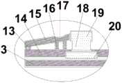
Fig. 2 is a schematic structural diagram of a fixing block of a storage box device of an electric vehicle.
Fig. 3 is a schematic structural view of an extended storage box device of an electric vehicle.
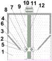
Fig. 4 is a schematic structural diagram of a storage box device of an electric vehicle in a side view.
In the figure: 1-base, 2-elastic band, 3-front fixed block, 4-fixed box plate, 5-rear fixed block, 6-connecting rod, 7-moving block, 8-sliding block, 9-sliding groove, 10-fixed frame, 11-motor, 12-threaded rod, 13-rotating shaft, 14-fixed plate, 15-fixed clamping plate, 16-pressing spring, 17-pressing groove, 18-fixed clamping seat, 19-fixed stop block and 20-cushion seat. Detailed description of the inventiontechnical solutions in the embodiments of the present invention will be clearly and completely described below with reference to the accompanying drawings in the embodiments of the present invention, and it is apparent that the described embodiments are only a part of the embodiments of the present invention, and not all of the embodiments. All other embodiments, which can be derived by a person skilled in the art from the embodiments given herein without making any creative effort, shall fall within the protection scope of the present invention. Referring to fig. 1 to 4, in an embodiment of the present invention, a storage box device of an electric vehicle includes abase 1, an elastic band 2, and afixed box plate 4; the upper side of one end of the upper surface of thebase 1 is fixedly connected with afixed box plate 4, a threadedrod 12 is arranged in the middle position of the front surfaces of thebase 1 and thefixed box plate 4, one side end of the threadedrod 12 penetrates and extends to the outer side of thefixed box plate 4, amotor 11 is arranged at the penetrating end of the threadedrod 12, afixed frame 10 is arranged between the two ends of themotor 11 and the fixed connection of thefixed box plate 4, slidinggrooves 9 are formed in thebase 1 at the two ends of the threadedrod 12, a movingblock 7 is connected to the threadedrod 12 in a sliding mode, sliding blocks 8 are arranged at the corresponding connection positions of the two sides of the lower end of the movingblock 7 and thesliding grooves 9, and connectingrods 6 are arranged in the middle positions of the two ends of the movingblock 7; arear fixing block 5 is arranged at the end part of one side of the connectingrod 6 far away from the movingblock 7,front fixing blocks 3 are arranged at the end parts of the two sides of thefixed box plate 4 far away from themotor 11, an elastic belt 2 is arranged between the connection parts of thefront fixing blocks 3 and therear fixing blocks 5, and afixing plate 14 is arranged between the end parts of the two sides of the elastic belt 2 and the fixed connection of thefront fixing block 3 and therear fixing block 5, afixing clamping seat 18 is arranged at the middle position of the upper surfaces of thefront fixing block 3 and therear fixing block 5, afixed stop block 19 is arranged at the inner side of the upper end of thefixing clamping seat 18,pad seats 20 are arranged at the lower sides of the two ends of thefixing clamping seat 18, a rotatingshaft 13 is arranged at the end part of one side of thefixing plate 14 far away from the elastic belt 2, an inclined fixedclamping plate 15 is arranged at the upper end part of the rotatingshaft 13, apressing spring 16 is arranged between the lower side of one end, far away from the rotatingshaft 13, of the fixedclamping plate 15 and thefixed plate 14, and apressing groove 17 is arranged at the upper side of one end, far away from the rotatingshaft 13, of the fixedclamping plate 15. The inner lower side of the fixedclamping seat 18 is provided with an empty groove, and thefixed plate 14 is arranged corresponding to the empty groove. The inclined end of the fixedclamping plate 15 is arranged corresponding to thefixed stop 19. The height of the elastic band 2 is consistent with that of thefixed box plate 4. Themotor 1 is electrically connected with an external power supply. The working principle of the invention is as follows: the invention relates to a storage box device of an electric automobile, which is suitable for various storage box occasions, when in use,fixing plates 14 at two ends of an elastic belt 2 are respectively clamped into fixingclamping seats 18 on afront fixing block 3 and arear fixing block 5, and afixing clamping plate 15 is upwards restored under the action of the elastic force of apressing spring 16 and is correspondingly abutted against afixing stop block 19, so that thefixing plates 14 and thefixing clamping plate 15 are fixed with thefront fixing block 3 and therear fixing block 5, the elastic belt 2 is further fixedly connected with thefront fixing block 3 and therear fixing block 5, and the elastic belt 2 is convenient to replace; after installing the elastic band,starter motor 11 drives threadedrod 12 and rotates, further makemovable block 7 drive the elastic band 2 at its both ends and extend and contract, the area increase and decrease of elastic band 2 and fixedbox board 4 of being convenient for, the area to the storing box body is adjusted according to the size is suitable of real object, so that placing object, also be convenient for adjust it according to the space size in the car, the size can be adjusted in the storing box space, be convenient for from the car integral erection and dismantlement and low in manufacturing cost, the cycle is short, and simple process, convenient operation is swift to use. It will be evident to those skilled in the art that the invention is not limited to the details of the foregoing illustrative embodiments, and that the present invention may be embodied in other specific forms without departing from the spirit or essential attributes thereof. The present embodiments are therefore to be considered in all respects as illustrative and not restrictive, the scope of the invention being indicated by the appended claims rather than by the foregoing description, and all changes which come within the meaning and range of equivalency of the claims are therefore intended to be embraced therein. Any reference sign in a claim should not be construed as limiting the claim concerned. Furthermore, it should be understood that although the present description refers to embodiments, not every embodiment may contain only a single embodiment, and such description is for clarity only, and those skilled in the art should integrate the description, and the embodiments may be combined as appropriate to form other embodiments understood by those skilled in the art.

Claims (5)

1. A storage box device of an electric automobile comprises a base (1), an elastic band (2) and a fixed box plate (4); the movable type automatic cutting machine is characterized in that a fixed box plate (4) is fixedly connected to the upper side of one end of the upper surface of a base (1), a threaded rod (12) is arranged at the middle position of the front surfaces of the base (1) and the fixed box plate (4), one end of the threaded rod (12) penetrates through the outer side of the fixed box plate (4) and extends to the outer side of the fixed box plate (4), a motor (11) is arranged at the penetrating end of the threaded rod (12), a fixed frame (10) is arranged between the two ends of the motor (11) and the fixed box plate (4), sliding grooves (9) are formed in the base (1) at the two ends of the threaded rod (12), a movable block (7) is connected onto the threaded rod (12) in a sliding mode, sliding blocks (8) are arranged at the corresponding connection positions of the two sides of the lower end of the movable block (7) and the sliding grooves (9), and connecting rods (6) are arranged at the middle positions of the two ends of the movable block (7);
a rear fixing block (5) is arranged at one side end part of the connecting rod (6) far away from the moving block (7), front fixing blocks (3) are arranged at two side end parts of the fixing box plates (4) far away from the motor (11), an elastic band (2) is arranged between the front fixing blocks (3) and the rear fixing blocks (5), fixing plates (14) are arranged between the two side end parts of the elastic band (2) and the fixing connection parts of the front fixing blocks (3) and the rear fixing blocks (5), fixing clamping seats (18) are arranged at the middle positions of the upper surfaces of the front fixing blocks (3) and the rear fixing blocks (5), fixing blocks (19) are arranged at the inner sides of the upper ends of the fixing clamping seats (18), cushion seats (20) are arranged at the lower sides of two ends of the fixing clamping seats (18), a rotating shaft (13) is arranged at one side end part of the fixing plates (14) far away from the elastic band (2), and an inclined fixing clamping plate (15) is arranged at the upper side end part of the rotating shaft (13), a pressing spring (16) is arranged between the lower side of one end, far away from the rotating shaft (13), of the fixing clamping plate (15) and the fixing plate (14), and a pressing groove (17) is arranged on the upper side of one end, far away from the rotating shaft (13), of the fixing clamping plate (15).
CN201811539338.9A2018-12-142018-12-14Storage box device of electric automobileActiveCN109606268B (en)

Priority Applications (1)

Application NumberPriority DateFiling DateTitle
CN201811539338.9ACN109606268B (en)2018-12-142018-12-14Storage box device of electric automobile

Applications Claiming Priority (1)

Application NumberPriority DateFiling DateTitle
CN201811539338.9ACN109606268B (en)2018-12-142018-12-14Storage box device of electric automobile

Publications (2)

Publication NumberPublication Date
CN109606268A CN109606268A (en)2019-04-12
CN109606268Btrue CN109606268B (en)2021-10-29

Family

ID=66010169

Family Applications (1)

Application NumberTitlePriority DateFiling Date
CN201811539338.9AActiveCN109606268B (en)2018-12-142018-12-14Storage box device of electric automobile

Country Status (1)

CountryLink
CN (1)CN109606268B (en)

Families Citing this family (1)

* Cited by examiner, † Cited by third party
Publication numberPriority datePublication dateAssigneeTitle
CN110584374A (en)*2019-08-242019-12-20汪扬皓Piano stool

Citations (7)

* Cited by examiner, † Cited by third party
Publication numberPriority datePublication dateAssigneeTitle
US4844305A (en)*1986-10-151989-07-04Mckneely James WCargo compartment organizer
US6488168B1 (en)*2001-07-202002-12-03Chu-Li WangArticle-storing box placed in an automobile trunk
CN107054229A (en)*2017-06-192017-08-18安徽江淮汽车集团股份有限公司A kind of automobile storage box
CN206870969U (en)*2017-05-112018-01-12浙江阜康机械有限公司Roof carrier for vehicles
CN108099796A (en)*2017-12-182018-06-01合肥亿恒智能科技股份有限公司A kind of separating device of automobile trunk
CN207657722U (en)*2017-11-162018-07-27南京视莱尔汽车电子有限公司A kind of automobile parcel tray
CN207931612U (en)*2018-03-212018-10-02重庆缘得科技有限公司A kind of new suitcase parcel tray

Family Cites Families (4)

* Cited by examiner, † Cited by third party
Publication numberPriority datePublication dateAssigneeTitle
DE102007042365A1 (en)*2007-09-062009-03-12GM Global Technology Operations, Inc., Detroit Guide unit for a height-adjustable loading floor and motor vehicle with such a guide unit and a height-adjustable loading floor
US9321402B2 (en)*2014-01-222016-04-26Ford Global Technologies, LlcMulti-function automotive trunk storage drawer
US10166928B2 (en)*2016-07-132019-01-01Ford Global Technologies, LlcStorage compartment divider having partition with hinged telescoping sections
EP3284686B1 (en)*2016-08-162018-12-26Neopost TechnologiesDevice and method for assembling items for shipment

Patent Citations (7)

* Cited by examiner, † Cited by third party
Publication numberPriority datePublication dateAssigneeTitle
US4844305A (en)*1986-10-151989-07-04Mckneely James WCargo compartment organizer
US6488168B1 (en)*2001-07-202002-12-03Chu-Li WangArticle-storing box placed in an automobile trunk
CN206870969U (en)*2017-05-112018-01-12浙江阜康机械有限公司Roof carrier for vehicles
CN107054229A (en)*2017-06-192017-08-18安徽江淮汽车集团股份有限公司A kind of automobile storage box
CN207657722U (en)*2017-11-162018-07-27南京视莱尔汽车电子有限公司A kind of automobile parcel tray
CN108099796A (en)*2017-12-182018-06-01合肥亿恒智能科技股份有限公司A kind of separating device of automobile trunk
CN207931612U (en)*2018-03-212018-10-02重庆缘得科技有限公司A kind of new suitcase parcel tray

Also Published As

Publication numberPublication date
CN109606268A (en)2019-04-12

Similar Documents

PublicationPublication DateTitle
CN109454552B (en)Clamp for processing steel backing of brake pad
CN109606268B (en)Storage box device of electric automobile
CN105171569A (en)Panel polishing machine
KR102044253B1 (en)Clamping jig for processing battery case of electric vehicle
CN113478324A (en)Grinding device for producing battery steel shell
CN210628361U (en)New energy automobile battery that takes precautions against earthquakes
CN210907726U (en)Shaping die for door corner fitting
CN116673379B (en)Automobile support stamping forming die
CN214869532U (en)Corner grinding device of automobile injection molding
CN203380316U (en)Riveting machine
CN211733057U (en)Get a manipulator with unhairing limit function
CN202894098U (en)Riveting jig for cover plate of lock housing of ignition lock for vehicle
CN204366333U (en)A kind of fixed mechanism carrying out welding for arm shaft
CN213765485U (en)Positioning tool for new energy automobile part machining
CN204075638U (en)Shock absorber drawing work platform
CN219543211U (en)Blanking manipulator capable of being attached at multiple angles for producing automobile plastic parts
CN212634826U (en) A welding and positioning tool for fixing base of automobile coat rack
CN213212288U (en)Battery box of electric vehicle
CN212909290U (en)Business turn over station shaping device is used in electric automobile motor production
CN215614485U (en)Cloud bus treater upper cover machine-shaping mould
CN221695914U (en)Tool for sealing ring pressing-in system
CN117753847B (en)Automotive interior spare mold processing with buffer function
CN218018813U (en)Auxiliary clamping mechanism for manufacturing automobile luggage compartment
CN212219263U (en)Plastic thread rolling die
CN217194981U (en)Rotary clamping tool for automobile parts

Legal Events

DateCodeTitleDescription
PB01Publication
PB01Publication
SE01Entry into force of request for substantive examination
TA01Transfer of patent application right

Effective date of registration:20210918

Address after:237000 jw-13, Jintiandi Trade City, Yeji District, Lu'an City, Anhui Province

Applicant after:Anhui Enterprise Development Productivity Promotion Center Co.,Ltd.

Address before:721000 No. 6, building 5, No. 102, Baofu Road, Jintai District, Baoji City, Shaanxi Province

Applicant before:Diao Chundi

GR01Patent grant
GR01Patent grant
CP01Change in the name or title of a patent holder

Address after:237000 jw-13, Jintiandi Trade City, Yeji District, Lu'an City, Anhui Province

Patentee after:Anhui Zece Technology Co.,Ltd.

Address before:237000 jw-13, Jintiandi Trade City, Yeji District, Lu'an City, Anhui Province

Patentee before:Anhui Enterprise Development Productivity Promotion Center Co.,Ltd.

TR01Transfer of patent right

Effective date of registration:20240315

Address after:247000 Jiandong Village, Yaodu Town, Dongzhi County, Chizhou City, Anhui Province

Patentee after:Anhui Huapeng Power Equipment Investment Co.,Ltd.

Country or region after:China

Address before:237000 jw-13, Jintiandi Trade City, Yeji District, Lu'an City, Anhui Province

Patentee before:Anhui Zece Technology Co.,Ltd.

Country or region before:China


[8]ページ先頭

©2009-2025 Movatter.jp