CN109544628B - Accurate reading identification system and method of a pointer meter - Google Patents
Accurate reading identification system and method of a pointer meterDownload PDFInfo
- Publication number
- CN109544628B CN109544628BCN201811406269.4ACN201811406269ACN109544628BCN 109544628 BCN109544628 BCN 109544628BCN 201811406269 ACN201811406269 ACN 201811406269ACN 109544628 BCN109544628 BCN 109544628B
- Authority
- CN
- China
- Prior art keywords
- pointer
- image
- camera
- plane
- meter
- Prior art date
- Legal status (The legal status is an assumption and is not a legal conclusion. Google has not performed a legal analysis and makes no representation as to the accuracy of the status listed.)
- Active
Links
Images


Classifications
- G—PHYSICS
- G06—COMPUTING OR CALCULATING; COUNTING
- G06T—IMAGE DATA PROCESSING OR GENERATION, IN GENERAL
- G06T7/00—Image analysis
- G06T7/70—Determining position or orientation of objects or cameras
- G—PHYSICS
- G06—COMPUTING OR CALCULATING; COUNTING
- G06T—IMAGE DATA PROCESSING OR GENERATION, IN GENERAL
- G06T7/00—Image analysis
- G06T7/80—Analysis of captured images to determine intrinsic or extrinsic camera parameters, i.e. camera calibration
- G06T7/85—Stereo camera calibration
- G—PHYSICS
- G06—COMPUTING OR CALCULATING; COUNTING
- G06V—IMAGE OR VIDEO RECOGNITION OR UNDERSTANDING
- G06V10/00—Arrangements for image or video recognition or understanding
- G06V10/20—Image preprocessing
- G06V10/26—Segmentation of patterns in the image field; Cutting or merging of image elements to establish the pattern region, e.g. clustering-based techniques; Detection of occlusion
- G06V10/267—Segmentation of patterns in the image field; Cutting or merging of image elements to establish the pattern region, e.g. clustering-based techniques; Detection of occlusion by performing operations on regions, e.g. growing, shrinking or watersheds
- G—PHYSICS
- G06—COMPUTING OR CALCULATING; COUNTING
- G06V—IMAGE OR VIDEO RECOGNITION OR UNDERSTANDING
- G06V10/00—Arrangements for image or video recognition or understanding
- G06V10/20—Image preprocessing
- G06V10/30—Noise filtering
- G—PHYSICS
- G06—COMPUTING OR CALCULATING; COUNTING
- G06V—IMAGE OR VIDEO RECOGNITION OR UNDERSTANDING
- G06V10/00—Arrangements for image or video recognition or understanding
- G06V10/40—Extraction of image or video features
- G06V10/48—Extraction of image or video features by mapping characteristic values of the pattern into a parameter space, e.g. Hough transformation
Landscapes
- Engineering & Computer Science (AREA)
- Physics & Mathematics (AREA)
- General Physics & Mathematics (AREA)
- Theoretical Computer Science (AREA)
- Multimedia (AREA)
- Computer Vision & Pattern Recognition (AREA)
- Length Measuring Devices By Optical Means (AREA)
Abstract
Translated fromChinese
Description
Translated fromChinese技术领域technical field
本发明涉及机器视觉领域,具体涉及一种指针式仪表的准确读数识别系统及方法。The invention relates to the field of machine vision, in particular to an accurate reading identification system and method of a pointer type instrument.
背景技术Background technique
随着仪器仪表技术的快速发展,仪器仪表被广泛的应用于各行各业,仪表数量繁多,需求量大。指针式仪表的使用在我国许多工厂、交通设备中仍然有不可替代的地位。指针式仪表的优点是结实耐用、价格便宜,并且其示数的波动(即指针的摆动)能形象的表示出参数的变化,此外其比较突出的优点是:对于一些特殊的场合,机械式指针仪表其防冻特性都能让其很好地在天气寒冷的地方工作、其防水特性能让其在水下工作,这些特性让其发挥在恶劣环境下仍能正常工作的优势。With the rapid development of instrumentation technology, instruments are widely used in all walks of life, with a large number of instruments and a large demand. The use of pointer instruments still has an irreplaceable position in many factories and transportation equipment in our country. The advantages of the pointer meter are that it is durable and cheap, and the fluctuation of its indication (that is, the oscillation of the pointer) can visually represent the change of the parameter. In addition, its more prominent advantages are: for some special occasions, the mechanical pointer The antifreeze properties of the instrument make it work well in cold weather, and its waterproof properties allow it to work underwater. These features allow it to work well in harsh environments.
某些数字仪表内置数据发送模块,自动将仪表读数发送到控制中心,但是这种技术必须要内置相应模块,而且成本较高,不可能用于现阶段已经安装的固定仪表中。因此,有必要开发一种指针式仪表的准确读数识别系统及方法,在不对现有仪表进行改装的基础上,不仅改变传统的人工实施仪表识别劳动强度大、生产效率低的缺陷,有效减少检测过程中的人力消耗,节省了资源,同时消除人工读取时由于观测人员的不同所可能导致读取的结果不同及存在较大偏差。因此,我们可以利用机器视觉的方法,通过相机采集图像并利用算法识别出图像中指针式仪表所指向位置的读数,以此替代人工读数。Some digital meters have a built-in data transmission module, which automatically sends the meter readings to the control center, but this technology must have a built-in corresponding module, and the cost is high, and it is impossible to use it in the fixed meters that have been installed at this stage. Therefore, it is necessary to develop an accurate reading recognition system and method for a pointer-type meter. On the basis of not modifying the existing meter, it not only changes the traditional manual implementation of the meter to identify the defects of high labor intensity and low production efficiency, but also effectively reduces the detection and detection. The labor consumption in the process saves resources, and at the same time eliminates the different reading results and large deviations that may be caused by different observers during manual reading. Therefore, we can use the method of machine vision to collect images through cameras and use algorithms to identify the readings of the positions pointed by the pointer meters in the images to replace manual readings.
现存的许多解决方案多数是直接处理仪表图像,直接读出图片中指针指向的示数。然而,当指针平面与仪表盘平面存在较明显的高度差时,这类解决方案就将出现问题。这是由于采集设备视角不同,造成指针在仪表平面的成像位置不同,这意味着当图像采集设备光轴未与仪表平面垂直或未在仪表中心正上方时(即相机倾斜和相机光轴中心未对准表盘中心),使得光轴与仪表中心点存在倾角。这时,采集得到的指针图像可能发生视角、尺度、倾斜等变化,导致从图像上直接读取指针所指示的数值是存在明显偏差的。这个问题导致指针式仪表读数的识别错误及准确率降低,目前仍然有待解决。Most of the existing solutions are to directly process the instrument image and directly read the indication pointed to by the pointer in the picture. However, when there is a significant height difference between the needle plane and the instrument panel plane, this type of solution will be problematic. This is due to the different viewing angles of the acquisition device, resulting in different imaging positions of the pointer on the instrument plane, which means that when the optical axis of the image acquisition device is not perpendicular to the instrument plane or is not directly above the center of the instrument (that is, the camera is tilted and the center of the camera optical axis is not Align the center of the dial), so that the optical axis is inclined to the center point of the meter. At this time, the angle, scale, and inclination of the acquired pointer image may change, resulting in obvious deviations in reading the value indicated by the pointer directly from the image. This problem has resulted in incorrect identification and reduced accuracy of pointer meter readings, and remains to be resolved.
发明内容SUMMARY OF THE INVENTION
有鉴于此,本发明的目的在于提供一种指针式仪表的准确读数识别系统及方法,解决了现有读数识别技术从图像上直接读取指针所指示的数值时存在的偏差问题。In view of this, the purpose of the present invention is to provide an accurate reading identification system and method of a pointer type instrument, which solves the deviation problem existing in the existing reading identification technology when the value indicated by the pointer is directly read from the image.
为实现上述目的,本发明采用如下技术方案:To achieve the above object, the present invention adopts the following technical solutions:
一种指针式仪表的准确读数识别系统,包括依次连接的图像采集模块、图像预处理模块、三维校正模块和识别结果输出模块;An accurate reading identification system of a pointer type instrument, comprising an image acquisition module, an image preprocessing module, a three-dimensional correction module and an identification result output module connected in sequence;
所述图像采集模块:用于采集仪表表盘双目图像,完成图像数据的稳定传输;The image acquisition module: used to collect the binocular image of the instrument panel to complete the stable transmission of image data;
图像预处理模块:用于对图像进行预处理和提取表盘主要刻度及指针针尖图像像素坐标;Image preprocessing module: used to preprocess the image and extract the main scale of the dial and the pixel coordinates of the pointer tip image;
三维检测校正模块:用于获取针尖三维信息,实现指针针尖的三维重定位和读数识别前的指针位置校正;Three-dimensional detection and correction module: used to obtain the three-dimensional information of the needle tip, realize the three-dimensional repositioning of the pointer needle tip and the correction of the pointer position before reading recognition;
识别结果输出模块:通过指针针尖与主要刻度的位置关系,计算读数结果。Recognition result output module: Calculate the reading result through the positional relationship between the pointer tip and the main scale.
进一步的,所述图像采集模块采用两个相同的摄像机组成的双目摄像机。Further, the image acquisition module adopts a binocular camera composed of two identical cameras.
一种指针式仪表的准确读数识别系统的识别方法,,包括以下步骤:An identification method for an accurate reading identification system of a pointer instrument, comprising the following steps:
步骤S1:对双目摄像机进行双目标定,获取双目摄像机的内参和外参;Step S1: perform dual target determination on the binocular camera, and obtain the internal and external parameters of the binocular camera;
步骤S2:通过标定后的双目摄像机采集得到图像,并利用获取的内参实现立体水平校正,使得左右图像对齐,并将图像输入至图像预处理模块;Step S2: acquiring an image through the calibration of the binocular camera, and utilizing the acquired internal parameters to achieve stereo level correction, so that the left and right images are aligned, and the image is input to the image preprocessing module;
步骤S3:通过图像预处模块提高初始图像质量,提取表盘主要刻度及指针针尖图像像素坐标,并输入至三维检测模块;Step S3: improving the initial image quality through the image preprocessing module, extracting the main scale of the dial and the pixel coordinates of the pointer tip image, and inputting them to the three-dimensional detection module;
步骤S4:三维检测校正模块利用双目检测算法,实现仪表三维化,并计算指针针尖三维信息和表盘平面三维信息,构建出仪表盘平面和指针针尖相对位置关系;Step S4: the three-dimensional detection and correction module uses the binocular detection algorithm to realize the three-dimensionalization of the instrument, and calculates the three-dimensional information of the needle tip of the pointer and the three-dimensional information of the dial plane, and constructs the relative positional relationship between the plane of the instrument panel and the needle tip of the pointer;
步骤S5:三维检测校正模块通过坐标系转换关系和垂直投影,对指针在仪表盘平面重定位,以完成对指针位置的校正;Step S5: the three-dimensional detection and correction module repositions the pointer on the plane of the instrument panel through the coordinate system conversion relationship and vertical projection, so as to complete the correction of the pointer position;
步骤S6:识别结果输出模块根据已提取主要刻度和指针针尖坐标位置信息,计算输出最终读数识别结果。Step S6: The recognition result output module calculates and outputs the final reading recognition result according to the extracted main scale and the coordinate position information of the pointer tip.
进一步的,所述双目摄像机的内参包括两个摄像机方向的焦距和相机成像中心;双目摄像机的外参包括旋转矩阵、平移向量和视差。Further, the internal parameters of the binocular camera include the focal lengths of the two camera directions and the camera imaging center; the external parameters of the binocular camera include a rotation matrix, a translation vector and a parallax.
进一步的,所述步骤S3具体为:Further, the step S3 is specifically:
步骤S31:采用分段线性变换法对图像进行增强处理;Step S31: adopt piecewise linear transformation method to carry out enhancement processing to the image;
步骤S32:采用二维中值滤波对图像进行去噪处理,消除或者减小采集过程中噪声所造成的影响;Step S32: adopting two-dimensional median filtering to denoise the image to eliminate or reduce the impact caused by noise in the acquisition process;
步骤S33:根据HSV的值确定最佳阈值进行分割,运用腐蚀运算、膨胀运算,减少针尖附近干扰数据;Step S33: determine the optimal threshold for segmentation according to the value of HSV, and use corrosion calculation and expansion calculation to reduce interference data near the needle tip;
步骤S34:提取出指针仪表的主要刻度信息,从而确定刻度盘起始和结束范围,得到任意3对点像素坐标;Step S34: extract the main scale information of the pointer meter, thereby determine the dial start and end range, obtain any 3 pairs of pixel coordinates;
步骤S35:通过Hough变换获取仪表指针,计算通过Hough变换得到直线的交点,即指针针尖在图像中的像素坐标位置。Step S35: Obtain the meter pointer through Hough transformation, and calculate the intersection of the straight lines obtained through Hough transformation, that is, the pixel coordinate position of the pointer tip in the image.
进一步的所述步骤S4具体为:The further described step S4 is specifically:
步骤S41:根据摄像机的内参,并利用Bouquet校正算法对双目图像进行水平校正;Step S41: according to the internal reference of the camera, and utilize the Bouquet correction algorithm to carry out horizontal correction to the binocular image;
步骤S42:利用双目检测算法,获得针尖的深度信息和仪表盘的深度信息;Step S42: use binocular detection algorithm to obtain the depth information of the needle tip and the depth information of the instrument panel;
步骤S43:通过像素坐标系、图像坐标系、相机坐标系和世界坐标系4种坐标系之间的转换关系,根据得到任意3对点像素坐标和相机视差D,利用双目检测算法,计算获得各点对应的深度z,计算公式如下:Step S43: Through the conversion relationship between the four coordinate systems of the pixel coordinate system, the image coordinate system, the camera coordinate system and the world coordinate system, according to obtaining any 3 pairs of pixel coordinates and the camera parallax D, the binocular detection algorithm is used to calculate and obtain. The depth z corresponding to each point is calculated as follows:

其中,x,y,z 是二维平面点经过计算后在三维空间坐标系中对应点的坐标。Among them, x, y, z are the coordinates of the corresponding point in the three-dimensional space coordinate system after the two-dimensional plane point is calculated.
步骤S44:根据指针针尖点和仪表盘上3对点像素坐标信息重建出仪表盘所在平面S,建立仪表盘平面的空间方程,并利用空间关系,获取指针针尖在仪表盘空间平面位置上垂直投影的交点三维坐标。Step S44: reconstruct the plane S where the instrument panel is located according to the pointer tip point and the pixel coordinate information of the three pairs of points on the instrument panel, establish the space equation of the instrument panel plane, and use the spatial relationship to obtain the vertical projection of the pointer needle tip on the position of the instrument panel space plane The 3D coordinates of the intersection point.
进一步的所述步骤S5具体为:The further described step S5 is specifically:
根据得到的指针针尖在仪表盘空间平面位置上垂直投影的交点三维坐标求取其在图像像素平面的映射点;According to the obtained three-dimensional coordinates of the intersection point of the vertical projection of the needle tip on the instrument panel space plane position, its mapping point in the image pixel plane is obtained;
进一步的所述步骤S6具体为:The further described step S6 is specifically:
步骤S61:利用极坐标与笛卡尔坐标系对应方程,将圆形刻度轴转换为笛卡尔坐标系;Step S61: utilize polar coordinates and the corresponding equation of the Cartesian coordinate system to convert the circular scale axis into the Cartesian coordinate system;
步骤S62:根据针尖所处位置占量程的比与量程的乘积,即是当前时刻指针所指向的准确读数t,可以得到:Step S62: According to the product of the ratio of the position of the needle tip to the measuring range and the measuring range, that is, the accurate reading t pointed by the pointer at the current moment, it can be obtained:

其中,Xp为指针针尖水平方向像素坐标值,Xstart为刻度起始位置水平方向像素值,Xend为刻度末端位置水平方向像素值,range为该指针式仪表量程。Among them,Xp is the horizontal pixel coordinate value of the pointer tip,Xstart is the horizontal pixel value of the scale start position,Xend is the horizontal pixel value of the scale end position, and range is the range of the pointer meter.
本发明与现有技术相比具有以下有益效果:Compared with the prior art, the present invention has the following beneficial effects:
本发明能够解决当仪表指针与仪表平面存在一定高度差,采集设备倾斜时采集到的图像中指针在表盘上投影位置与实际位置不符,而导致读数准确度下降甚至读数错误问题。The invention can solve the problem that when the meter pointer and the meter plane have a certain height difference, the projected position of the pointer on the dial does not match the actual position in the image collected when the collecting device is tilted, resulting in decreased reading accuracy or even wrong reading.
附图说明Description of drawings
图1是本发明实施例中一种指针式仪表示意图;1 is a schematic diagram of a pointer type meter in an embodiment of the present invention;
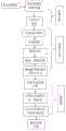
图2是本发明方法流程图;Fig. 2 is the flow chart of the method of the present invention;
图3是本发明实施例中双目立体视觉成像原理图;3 is a schematic diagram of binocular stereo vision imaging in an embodiment of the present invention;
图4是本发明实施例中指针重定位原理图。FIG. 4 is a schematic diagram of pointer relocation in an embodiment of the present invention.
具体实施方式Detailed ways
下面结合附图及实施例对本发明做进一步说明。The present invention will be further described below with reference to the accompanying drawings and embodiments.
请参照图1,本发明提供一种指针式仪表的准确读数识别系统,包括依次连接的图像采集模块、图像预处理模块、三维校正模块和识别结果输出模块;所述图像采集模块:用于采集仪表表盘双目图像,完成图像数据的稳定传输;图像预处理模块:用于对图像进行预处理和提取表盘主要刻度及指针针尖图像像素坐标;三维检测校正模块:用于获取针尖三维信息,实现指针针尖的三维重定位和读数识别前的指针位置校正;识别结果输出模块:通过指针针尖与主要刻度的位置关系,计算读数结果。Please refer to FIG. 1, the present invention provides an accurate reading recognition system of a pointer meter, including an image acquisition module, an image preprocessing module, a three-dimensional correction module and a recognition result output module connected in sequence; the image acquisition module: used for collecting The binocular image of the instrument panel is used to complete the stable transmission of image data; the image preprocessing module: used to preprocess the image and extract the main scale of the dial and the pixel coordinates of the pointer tip image; Three-dimensional repositioning of the pointer tip and correction of the pointer position before reading recognition; recognition result output module: Calculate the reading result through the positional relationship between the pointer tip and the main scale.
本实施例中,图像采集模块由两个规格相同CMOS摄像头,按照一定的距离平行放置,组装成一个双目摄像头,并且之后不再改变其相对位置。例如CMOS摄像头像素为1080×720像素,数据通过USB3.0接口传至计算机。In this embodiment, the image acquisition module is composed of two CMOS cameras with the same specifications, which are placed in parallel at a certain distance to form a binocular camera, and the relative positions thereof are not changed thereafter. For example, the pixels of the CMOS camera are 1080×720 pixels, and the data is transmitted to the computer through the USB3.0 interface.
在本实施例中,一种指针式仪表的准确读数识别系统的识别方法,具体包括以下步骤:In this embodiment, an identification method of an accurate reading identification system of a pointer meter specifically includes the following steps:
步骤S1:在正式开始测量读数之前,需要先对双目摄像机进行标定工作。在进行双目标定时,有两种常见的数据库:Matlab视觉处理库和OpenCV开源视觉库;其内部封装可用的摄像机标定算法。利用CMOS摄像机采集20幅不同姿态下的标定板图像,交与上述软件进行标定。通常Matlab中标定的结果比较稳定,可以在Matlab中标定之后再使用OpenCV标定。通过双目标定,可以获得以下几个参数:相机内参、畸变,包括径向畸变和切向畸变、相机外参,包括3*3旋转矩阵和3*1平移向量、两个相机间视差D。从作用上来看,内参数矩阵是为了得到镜头的信息,并消除畸变,使得到的图像更为准确,外参数矩阵是为了得到相机相对于世界坐标的联系,是为了最终的测距。Step S1: Before officially starting to measure and read, the binocular camera needs to be calibrated. For dual-target timing, there are two common databases: the Matlab vision processing library and the OpenCV open source vision library; which internally encapsulate the available camera calibration algorithms. Use a CMOS camera to collect 20 images of the calibration board under different attitudes, and submit them to the above software for calibration. Usually, the results of calibration in Matlab are relatively stable, and OpenCV can be used after calibration in Matlab. The following parameters can be obtained through dual-target positioning: camera internal parameters, distortion, including radial distortion and tangential distortion, camera external parameters, including 3*3 rotation matrix and 3*1 translation vector, and disparityD between two cameras. In terms of function, the internal parameter matrix is to obtain the information of the lens and eliminate distortion, so that the obtained image is more accurate, and the external parameter matrix is to obtain the relationship between the camera and the world coordinates, for the final ranging.
步骤S2: 标定工作完成后,可以实施图像的采集和识别过程。通过计算机控制两个摄像头同时拍摄图片,经过数据线将图像数据传至主机交与OpenCV程序处理。利用标定工作获取的两个相机的内参,包括两个方向的焦距fx、fy,相机成像中心Cx、Cy等参数,对两幅图像进行图像立体水平校正。使得物体在两个相机成像平面的投影点在满足极限约束定理的同时,对应的点能在同一水平面上。Step S2: After the calibration work is completed, the image acquisition and identification process can be implemented. The two cameras are controlled by the computer to take pictures at the same time, and the image data is transmitted to the host computer through the data line for processing by the OpenCV program. Using the internal parameters of the two cameras obtained in the calibration work, including the focal lengthsfx andfy in two directions, and the camera imaging centersCx andCy , the two images are subjected to image stereo level correction. Make the projection points of the object on the imaging planes of the two cameras satisfy the limit constraint theorem, and the corresponding points can be on the same horizontal plane.
步骤S3:对图像预处理,通过摄像机获取图像后,需要对图像进行处理。不仅是为了提高图像质量,更重要的是提取图像中有用信息。先对左图进行处理:(1)采用分段线性变换法对图像进行增强处理。(2)采用二维中值滤波对含有噪声的初始图像进行去噪处理,消除或者减小采集过程中噪声所造成的影响。(3)运用腐蚀运算、膨胀运算,减少针尖附近干扰数据。(4)利用对仪表实例的先验知识,根据HSV值确定最佳阈值,提取出指针仪表的主要刻度信息,从而确定刻度盘起始和结束范围,得到任意三点(Nx1-left,Ny1- left)、(Nx2- left,Ny2- left)、(Nx3- left, Ny3- left)(5)通过Hough变换获取仪表指针,进一步计算通过Hough变换得到直线的交点,即是我们需要的指针针尖在图像中的像素坐标位置(Px-left,Py-left)。此时,程序通过立体匹配算法可得,在右图中得到与左图一一对应的三点(Nx1-right,Ny1-right)、(Nx2-right,Ny2-right)、(Nx3-right, Ny3-right)和指针针尖像素坐标位置(Px-right,Py-right)。这里,在二维空间上匹配对应点是非常耗时的,为了减少匹配搜索范围,我们可以利用极线约束理论使得对应点的匹配由二维搜索降为一维搜索。Step S3: Preprocessing the image. After the image is acquired by the camera, the image needs to be processed. Not only to improve image quality, but more importantly to extract useful information from images. First process the left image: (1) Use piecewise linear transformation to enhance the image. (2) The two-dimensional median filter is used to denoise the initial image containing noise, so as to eliminate or reduce the influence caused by the noise in the acquisition process. (3) Use corrosion operation and expansion operation to reduce the interference data near the needle tip. (4) Using the prior knowledge of the instrument instance, determine the optimal threshold value according to the HSV value, extract the main scale information of the pointer instrument, thereby determine the start and end range of the dial, and obtain any three points (Nx1-left, Ny1- left ), (N x2-left, Ny2- left ), (Nx3- left, Ny3- left ) (5) Obtain the meter pointer through Hough transformation, and further calculate the intersection of the straight lines obtained through Hough transformation, that is We need the pixel coordinate position of the pointer tip in the image (Px-left, Py-left ). At this time, the program can be obtained through the stereo matching algorithm, and three points (Nx1-right, Ny1-right ), (Nx2-right, Ny2-right ), (Nx3-right, Ny3-right ) and the pixel coordinate position of the pointer tip (Px-right, Py-right ). Here, matching corresponding points in two-dimensional space is very time-consuming. In order to reduce the matching search range, we can use epipolar constraint theory to reduce the matching of corresponding points from two-dimensional search to one-dimensional search.
步骤S4:根据前述所确定的点,进入三维检测阶段。Step S4: According to the point determined above, enter the three-dimensional detection stage.
在摄像机的成像过程中,存在着四个坐标系,分别是:像素坐标系、图像坐标系、相机坐标系、以及世界坐标系。如图所示,像素坐标系以图像的左上角为原点O,横纵坐标(u,v)分别表示该像素点在图像中的列数和行数;图像坐标系的原点为相机的光轴与图像平面的交点,则点(u0,v0)在两坐标系之间存在如下关系:In the imaging process of the camera, there are four coordinate systems, namely: the pixel coordinate system, the image coordinate system, the camera coordinate system, and the world coordinate system. As shown in the figure, the pixel coordinate system takes the upper left corner of the image as the originO , and the horizontal and vertical coordinates (u,v ) represent the number of columns and rows of the pixel in the image respectively; the origin of the image coordinate system is the optical axis of the camera The intersection with the image plane, the point (u0, v0 ) has the following relationship between the two coordinate systems:

用齐次矩阵表示则为:Represented by a homogeneous matrix as:

进一步,由摄像机坐标系到图像坐标系的转化公式为:Further, the conversion formula from the camera coordinate system to the image coordinate system is:

用齐次矩阵表示如下(其中S为比例因子,f为焦距):It is represented by a homogeneous matrix as follows (whereS is the scale factor andf is the focal length):

世界坐标到相机坐标系的转换关系为:The conversion relationship from world coordinates to camera coordinate system is:

步骤S5:通过双目摄像机三维检测的手段,实现仪表指针针尖在仪表盘平面重定位。(1)根据前述计算得到的3对点和相机视差D,利用双目测距原理,计算获得各点对应的深度Z。利用3点的三维信息重建出这个表盘所在平面S1。其中,物体的三维坐标可以通过双目立体视觉技术来确定,如图3所示有OL和OR是左右相机的光心,它们的光轴和各自的成像平面。假设两相机的内部和外部参数完全相同,焦距为f,光心之间的距离(基线)为B,两台相机在同一平面上,因此他们的投影中心的Y轴坐标相等。同一时刻空间点P(x,y,z)在两相机上成像点分别为Pleft和Pright。Step S5: Realize the repositioning of the needle tip of the instrument pointer on the plane of the instrument panel by means of three-dimensional detection of the binocular camera. (1) According to the three pairs of points and the camera parallaxD calculated above, the depthZ corresponding to each point is obtained by using the principle of binocular ranging. The planeS1 where the dial is located is reconstructed by using the three-dimensional information of 3 points. Among them, the three-dimensional coordinates of the object can be determined by binocular stereo vision technology. As shown in Figure 3,OL andOR are the optical centers of the left and right cameras, their optical axes and their respective imaging planes. Assuming that the internal and external parameters of the two cameras are exactly the same, the focal length isf , the distance between the optical centers (baseline) isB , and the two cameras are in the same plane, so the Y-coordinates of their projection centers are equal. The imaging points of the space pointP(x, y, z) on the two cameras at the same time arePleft andPright , respectively.

引入参数视差D后可得:After introducing the parameter parallaxD , we can get:

(2)获得表盘平面上的圆心O2,通过该圆心作垂直于平面S1的垂线L;确定指针针尖P的空间坐标,并作一个过该针尖P点并同表盘平面S1平行的平面S2。平面S2与垂线L的交点O2,计算并记录O2P的斜率;在表盘平面S1上,通过圆心O1作与O2P相同斜率,即为指针相对于表盘平面的真实位置,见图4。(2) Obtain the circle centerO2 on the dial plane, and draw a vertical lineL perpendicular to the planeS1 through the center of the circle; determine the spatial coordinates of the pointer tipP , and make a pointP that passes through the needle tip and is parallel to the dial planeS1 . planeS2 . At the intersectionO2 of the planeS2 and the vertical lineL , calculate and record the slope ofO2P ; on the dial planeS1 , make the same slope asO2P through the centerO1 , that is, the real position of the pointer relative to the dial plane , see Figure 4.
步骤S6:指针式仪表读数识别:对三维重定位后的指针针尖的空间三维坐标求取其在图像像素平面的映射点。在确定了指针在成像平面的像素位置后,在前述字符、刻度识别的基础上,利用极坐标与笛卡尔坐标系对应方程,将圆形(弧形)坐标轴转换为极坐标系。根据指针到最近刻度线的距离,即可计算出图像指针读数。Step S6 : Recognition of the readings of the pointer type meter: The mapping point on the image pixel plane is obtained from the spatial three-dimensional coordinates of the pointer tip after the three-dimensional repositioning. After determining the pixel position of the pointer on the imaging plane, on the basis of the aforementioned character and scale recognition, the circular (arc) coordinate axis is converted into a polar coordinate system by using the equation corresponding to the polar coordinate and the Cartesian coordinate system. Based on the distance of the pointer to the nearest tick mark, the image pointer reading can be calculated.

其中,Xp为指针针尖水平方向像素坐标值,Xstart为刻度起始位置水平方向像素值,Xend为刻度末端位置水平方向像素值,range为该指针式仪表量程。Among them,Xp is the horizontal pixel coordinate value of the pointer tip,Xstart is the horizontal pixel value of the scale start position,Xend is the horizontal pixel value of the scale end position, and range is therange of the pointer meter.
本实施例中,使用OpenCV编写了读数识别的程序,可实现以上所述方法的功能:(1)读取摄像头拍摄获得的有效图片;(2)利用图像处理算法,从照片中读取并记录仪表指针针尖的位置和各个刻度坐标位置;(3)利用双目检测算法,将前述图像中指针针尖二维坐标转换为具备深度信息的三维坐标;(4)将指针针尖垂直投影到仪表盘所在的三维平面,并与图像像素平面实现映射。根据此时指针针尖位置和刻度位置信息,实现准确读数的功能。In this embodiment, a reading recognition program is written using OpenCV, which can realize the functions of the above-mentioned methods: (1) Read the valid pictures captured by the camera; (2) Use the image processing algorithm to read and record from the photos The position of the needle tip of the instrument pointer and the coordinate positions of each scale; (3) Using the binocular detection algorithm, convert the two-dimensional coordinates of the pointer tip in the above image into three-dimensional coordinates with depth information; (4) Project the needle tip vertically to where the instrument panel is located The 3D plane is mapped with the image pixel plane. According to the pointer tip position and scale position information at this time, the function of accurate reading is realized.
以上所述仅为本发明的较佳实施例,凡依本发明申请专利范围所做的均等变化与修饰,皆应属本发明的涵盖范围。The above descriptions are only preferred embodiments of the present invention, and all equivalent changes and modifications made according to the scope of the patent application of the present invention shall fall within the scope of the present invention.
Claims (4)
Translated fromChinese

Priority Applications (1)
| Application Number | Priority Date | Filing Date | Title |
|---|---|---|---|
| CN201811406269.4ACN109544628B (en) | 2018-11-23 | 2018-11-23 | Accurate reading identification system and method of a pointer meter |
Applications Claiming Priority (1)
| Application Number | Priority Date | Filing Date | Title |
|---|---|---|---|
| CN201811406269.4ACN109544628B (en) | 2018-11-23 | 2018-11-23 | Accurate reading identification system and method of a pointer meter |
Publications (2)
| Publication Number | Publication Date |
|---|---|
| CN109544628A CN109544628A (en) | 2019-03-29 |
| CN109544628Btrue CN109544628B (en) | 2021-08-31 |
Family
ID=65849722
Family Applications (1)
| Application Number | Title | Priority Date | Filing Date |
|---|---|---|---|
| CN201811406269.4AActiveCN109544628B (en) | 2018-11-23 | 2018-11-23 | Accurate reading identification system and method of a pointer meter |
Country Status (1)
| Country | Link |
|---|---|
| CN (1) | CN109544628B (en) |
Families Citing this family (12)
| Publication number | Priority date | Publication date | Assignee | Title |
|---|---|---|---|---|
| CN110414510B (en)* | 2019-07-26 | 2021-10-08 | 华中科技大学 | A kind of pointer meter reading correction method |
| CN112749598A (en)* | 2019-10-31 | 2021-05-04 | 中移物联网有限公司 | Information processing method, terminal and data platform of pointer type meter |
| CN111103533B (en)* | 2019-12-12 | 2020-09-25 | 常州机电职业技术学院 | Reset method of ten-position rotary dial switch reset system based on vision |
| CN111797909B (en)* | 2020-06-22 | 2024-03-29 | 上海工程技术大学 | Pointer type instrument reading method based on machine vision |
| CN112307887B (en)* | 2020-09-02 | 2023-04-21 | 国网浙江省电力有限公司嘉兴供电公司 | SF (sulfur hexafluoride) 6 Intelligent on-line monitoring and early warning method and system for gas pressure |
| CN112329770B (en)* | 2020-10-30 | 2024-02-23 | 江苏理工学院 | Instrument scale identification method and device |
| CN112257676B (en)* | 2020-11-19 | 2023-10-24 | 南京天创电子技术有限公司 | Pointer type instrument reading method and system and inspection robot |
| CN113487515B (en)* | 2021-07-26 | 2024-11-22 | 北京佳讯飞鸿电气股份有限公司 | Tilt correction method and tilt correction device for pointer type instrument image |
| CN114005108B (en)* | 2021-11-08 | 2025-05-06 | 国网上海市电力公司 | A method for identifying the degree of pointer instruments based on coordinate transformation |
| CN114676957A (en)* | 2022-01-27 | 2022-06-28 | 福建瑞达精工股份有限公司 | A data analysis system for assembly quality of watch products |
| CN114581673A (en)* | 2022-03-11 | 2022-06-03 | 中国科学院西安光学精密机械研究所 | A preprocessing method for image recognition of clock hands |
| CN116434214A (en)* | 2023-03-27 | 2023-07-14 | 深圳市铁越电气有限公司 | A method and system for reading a two-pointer instrument based on deep learning |
Citations (4)
| Publication number | Priority date | Publication date | Assignee | Title |
|---|---|---|---|---|
| JP4582863B2 (en)* | 2000-05-22 | 2010-11-17 | 株式会社バンダイナムコゲームス | Stereoscopic image display device and information storage medium |
| CN107145890A (en)* | 2017-05-02 | 2017-09-08 | 南通大学 | An automatic reading method of a pointer instrument panel in a long-distance multi-angle environment |
| CN107167169A (en)* | 2017-07-03 | 2017-09-15 | 吉林大学 | Readings of pointer type meters identification measuring method based on NI Vision Builder for Automated Inspection |
| CN108009535A (en)* | 2017-11-21 | 2018-05-08 | 武汉中元华电科技股份有限公司 | A kind of simple pointer meter reading method based on machine vision |
- 2018
- 2018-11-23CNCN201811406269.4Apatent/CN109544628B/enactiveActive
Patent Citations (4)
| Publication number | Priority date | Publication date | Assignee | Title |
|---|---|---|---|---|
| JP4582863B2 (en)* | 2000-05-22 | 2010-11-17 | 株式会社バンダイナムコゲームス | Stereoscopic image display device and information storage medium |
| CN107145890A (en)* | 2017-05-02 | 2017-09-08 | 南通大学 | An automatic reading method of a pointer instrument panel in a long-distance multi-angle environment |
| CN107167169A (en)* | 2017-07-03 | 2017-09-15 | 吉林大学 | Readings of pointer type meters identification measuring method based on NI Vision Builder for Automated Inspection |
| CN108009535A (en)* | 2017-11-21 | 2018-05-08 | 武汉中元华电科技股份有限公司 | A kind of simple pointer meter reading method based on machine vision |
Non-Patent Citations (4)
| Title |
|---|
| Auto-recognition Method for Pointer-type Meter Based on Binocular Vision;Biao Yang et al.;《Journal of computers》;20170430;第9卷(第4期);第787-793页* |
| 基于双目立体视觉的指针式仪表判读算法;赵焱 等;《传感器与微系统( Transducer and Microsystem Technologies)》;20200702;第39卷(第7期);第119-126页* |
| 基于机器视觉的指针式仪表读数识别系统研究;孙浩晏;《中国优秀硕士学位论文全文数据库 信息科技辑》;20150915(第9期);第I138-1413页* |
| 指针式仪表自动读数技术研究;李稷芳;《万方》;20101222;第1-60页* |
Also Published As
| Publication number | Publication date |
|---|---|
| CN109544628A (en) | 2019-03-29 |
Similar Documents
| Publication | Publication Date | Title |
|---|---|---|
| CN109544628B (en) | Accurate reading identification system and method of a pointer meter | |
| Liu et al. | Concrete crack assessment using digital image processing and 3D scene reconstruction | |
| CN112686877B (en) | Construction and measurement method and system of 3D house damage model based on binocular camera | |
| CN106599897B (en) | Readings of pointer type meters recognition methods and device based on machine vision | |
| CN103759671B (en) | A kind of dental model three-dimensional surface data non-contact scanning method | |
| CN102376089B (en) | Target correction method and system | |
| CN110414510B (en) | A kind of pointer meter reading correction method | |
| CN110672020A (en) | A method for measuring the height of standing trees based on monocular vision | |
| CN102221331B (en) | Measuring method based on asymmetric binocular stereovision technology | |
| CN111260720A (en) | A target height determination system based on deep learning method | |
| CN103456038A (en) | Method for rebuilding three-dimensional scene of downhole environment | |
| US20240394899A1 (en) | Method, Apparatus and Device for Photogrammetry, and Storage Medium | |
| CN105740856A (en) | Method for reading readings of pointer instrument based on machine vision | |
| CN102903101B (en) | Method for carrying out water-surface data acquisition and reconstruction by using multiple cameras | |
| TW201520508A (en) | System and method for interpolating points using contact probe | |
| CN205352391U (en) | Entity measurement system based on ground three -dimensional laser scanning | |
| CN105574812B (en) | Multi-angle three-dimensional data method for registering and device | |
| CN109974659A (en) | An embedded ranging system based on binocular machine vision | |
| CN109448043A (en) | Standing tree height extracting method under plane restriction | |
| CN110223355A (en) | A kind of feature mark poiX matching process based on dual epipolar-line constraint | |
| CN106296825A (en) | A kind of bionic three-dimensional information generating system and method | |
| CN104318566B (en) | Can return to the new multi-view images plumb line path matching method of multiple height values | |
| CN104167001B (en) | Large-visual-field camera calibration method based on orthogonal compensation | |
| CN109493378B (en) | Verticality detection method based on combination of monocular vision and binocular vision | |
| CN117451000A (en) | Intelligent rail train road subgrade settlement machine vision detection method and system |
Legal Events
| Date | Code | Title | Description |
|---|---|---|---|
| PB01 | Publication | ||
| PB01 | Publication | ||
| SE01 | Entry into force of request for substantive examination | ||
| SE01 | Entry into force of request for substantive examination | ||
| GR01 | Patent grant | ||
| GR01 | Patent grant |