CN109494889B - Electric energy generation method and wireless energy transmission device applicable thereto - Google Patents
Electric energy generation method and wireless energy transmission device applicable theretoDownload PDFInfo
- Publication number
- CN109494889B CN109494889BCN201710818260.3ACN201710818260ACN109494889BCN 109494889 BCN109494889 BCN 109494889BCN 201710818260 ACN201710818260 ACN 201710818260ACN 109494889 BCN109494889 BCN 109494889B
- Authority
- CN
- China
- Prior art keywords
- power
- electric energy
- circuit
- auxiliary
- transmitting
- Prior art date
- Legal status (The legal status is an assumption and is not a legal conclusion. Google has not performed a legal analysis and makes no representation as to the accuracy of the status listed.)
- Active
Links
Images


Classifications
- H—ELECTRICITY
- H02—GENERATION; CONVERSION OR DISTRIBUTION OF ELECTRIC POWER
- H02J—CIRCUIT ARRANGEMENTS OR SYSTEMS FOR SUPPLYING OR DISTRIBUTING ELECTRIC POWER; SYSTEMS FOR STORING ELECTRIC ENERGY
- H02J50/00—Circuit arrangements or systems for wireless supply or distribution of electric power
- H02J50/20—Circuit arrangements or systems for wireless supply or distribution of electric power using microwaves or radio frequency waves
- H—ELECTRICITY
- H02—GENERATION; CONVERSION OR DISTRIBUTION OF ELECTRIC POWER
- H02J—CIRCUIT ARRANGEMENTS OR SYSTEMS FOR SUPPLYING OR DISTRIBUTING ELECTRIC POWER; SYSTEMS FOR STORING ELECTRIC ENERGY
- H02J50/00—Circuit arrangements or systems for wireless supply or distribution of electric power
- H02J50/10—Circuit arrangements or systems for wireless supply or distribution of electric power using inductive coupling
- H—ELECTRICITY
- H02—GENERATION; CONVERSION OR DISTRIBUTION OF ELECTRIC POWER
- H02J—CIRCUIT ARRANGEMENTS OR SYSTEMS FOR SUPPLYING OR DISTRIBUTING ELECTRIC POWER; SYSTEMS FOR STORING ELECTRIC ENERGY
- H02J50/00—Circuit arrangements or systems for wireless supply or distribution of electric power
- H02J50/70—Circuit arrangements or systems for wireless supply or distribution of electric power involving the reduction of electric, magnetic or electromagnetic leakage fields
- H—ELECTRICITY
- H04—ELECTRIC COMMUNICATION TECHNIQUE
- H04B—TRANSMISSION
- H04B5/00—Near-field transmission systems, e.g. inductive or capacitive transmission systems
- H04B5/20—Near-field transmission systems, e.g. inductive or capacitive transmission systems characterised by the transmission technique; characterised by the transmission medium
- H04B5/24—Inductive coupling
- H04B5/26—Inductive coupling using coils
- H04B5/266—One coil at each side, e.g. with primary and secondary coils
- H—ELECTRICITY
- H04—ELECTRIC COMMUNICATION TECHNIQUE
- H04B—TRANSMISSION
- H04B5/00—Near-field transmission systems, e.g. inductive or capacitive transmission systems
- H04B5/70—Near-field transmission systems, e.g. inductive or capacitive transmission systems specially adapted for specific purposes
- H04B5/79—Near-field transmission systems, e.g. inductive or capacitive transmission systems specially adapted for specific purposes for data transfer in combination with power transfer
- H—ELECTRICITY
- H02—GENERATION; CONVERSION OR DISTRIBUTION OF ELECTRIC POWER
- H02J—CIRCUIT ARRANGEMENTS OR SYSTEMS FOR SUPPLYING OR DISTRIBUTING ELECTRIC POWER; SYSTEMS FOR STORING ELECTRIC ENERGY
- H02J50/00—Circuit arrangements or systems for wireless supply or distribution of electric power
- H02J50/80—Circuit arrangements or systems for wireless supply or distribution of electric power involving the exchange of data, concerning supply or distribution of electric power, between transmitting devices and receiving devices
- H—ELECTRICITY
- H04—ELECTRIC COMMUNICATION TECHNIQUE
- H04W—WIRELESS COMMUNICATION NETWORKS
- H04W4/00—Services specially adapted for wireless communication networks; Facilities therefor
- H04W4/80—Services using short range communication, e.g. near-field communication [NFC], radio-frequency identification [RFID] or low energy communication
- H—ELECTRICITY
- H04—ELECTRIC COMMUNICATION TECHNIQUE
- H04W—WIRELESS COMMUNICATION NETWORKS
- H04W84/00—Network topologies
- H04W84/02—Hierarchically pre-organised networks, e.g. paging networks, cellular networks, WLAN [Wireless Local Area Network] or WLL [Wireless Local Loop]
- H04W84/10—Small scale networks; Flat hierarchical networks
- H04W84/12—WLAN [Wireless Local Area Networks]
Landscapes
- Engineering & Computer Science (AREA)
- Computer Networks & Wireless Communication (AREA)
- Signal Processing (AREA)
- Power Engineering (AREA)
- Physics & Mathematics (AREA)
- Electromagnetism (AREA)
- Charge And Discharge Circuits For Batteries Or The Like (AREA)
Abstract
Description
Translated fromChinese技术领域technical field
本公开涉及一种电能产生方法及其适用的无线电能传输装置,特别涉及一种利用无线电能传输装置的发射侧所接收的电能来产生无线电能传输装置的接收侧的辅助电源的电能产生方法及其适用的无线电能传输装置。The present disclosure relates to an electric energy generation method and a wireless energy transmission device applicable thereto, and in particular to an electric energy generation method for generating an auxiliary power supply on the receiving side of the wireless energy transmission device by using electric energy received by the transmitting side of the wireless energy transmission device, and It applies to wireless power transfer devices.
背景技术Background technique
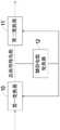
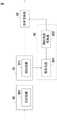
在电子装置中,通常须利用辅助电源来为电子装置内部的元器件(例如控制电路)进行供电,而对于一般的电子装置而言,其辅助电源的产生多源自电子装置内部的直流母线电能。图1为一种适用于电子装置的现有辅助电源产生方法的原理框图,如图1所示,此种现有辅助电能产生方法是利用第一变换器10接收输入交流电能,并变换为直流母线电能,并利用第二变换器11将直流母线电能变换为输出直流电能,且利用辅助电能变换器12将直流母线电能变换为辅助电能,使辅助电能可供第一变换器10及第二变换器11内部的元器件使用。由此可知,适用于电子装置的现有辅助电能产生方法是将电子装置所接收的输入交流电能变换为直流母线电能,再利用直流母线电能产生辅助电能。In an electronic device, it is usually necessary to use an auxiliary power supply to supply power to components inside the electronic device (such as a control circuit). For general electronic devices, the generation of the auxiliary power source mostly comes from the DC bus power inside the electronic device. . Fig. 1 is a functional block diagram of an existing auxiliary power generation method suitable for electronic devices. As shown in Fig. 1, this existing auxiliary power generation method is to use the
对于无线电能传输装置而言,无线电能传输装置的运行原理为利用发射侧所接收的输入电能而在发射侧的线圈产生高频交变电流,以产生交变磁场,再利用接收侧的线圈与发射侧的线圈的电磁耦合,使接收侧的线圈产生高频交变电流,藉此实现无线电能传输。For the wireless power transmission device, the operating principle of the wireless power transmission device is to use the input power received by the transmitting side to generate a high-frequency alternating current in the coil on the transmitting side to generate an alternating magnetic field, and then use the coil on the receiving side to The electromagnetic coupling of the coil on the transmitting side causes the coil on the receiving side to generate high-frequency alternating current, thereby realizing wireless energy transmission.
由于无线电能传输装置的发射侧的电路与接收侧的电路之间没有电气连接,因此当无线电能传输装置的接收侧需产生辅助电能来供接收侧的电路使用时,适用于无线电能传输装置的现有辅助电能产生方法便利用下列两种方式来实现。第一种现有辅助电能产生方法为当无线电能传输装置是用来对负载的功率电池进行充电时,无线电能传输装置的接收侧是直接利用负载的功率电池的电能来产生辅助电能。第二种现有辅助电能产生方法则是额外接入电池(例如干电池或蓄电池等)至无线电能传输装置的接收侧,以利用电池的电能来产生辅助电能。Since there is no electrical connection between the circuit on the transmitting side of the wireless power transmission device and the circuit on the receiving side, when the receiving side of the wireless power transmission device needs to generate auxiliary power for use by the circuit on the receiving side, it is applicable to the wireless power transmission device. The existing method for generating auxiliary electric energy is realized in the following two ways. The first existing auxiliary power generation method is that when the wireless power transmission device is used to charge the load's power battery, the receiving side of the wireless power transmission device directly uses the power of the load's power battery to generate auxiliary power. The second existing auxiliary power generation method is to additionally connect a battery (such as a dry battery or a storage battery) to the receiving side of the wireless power transmission device, so as to generate auxiliary power by using the electric energy of the battery.
然而,上述两种现有辅助电能产生方法皆利用电池作为无线电能传输装置的接收侧的辅助电能的能量来源,又电池在无线电能传输装置不运行时会持续有微弱放电,故容易造成电池过度放电,导致现有无线电能传输装置不但无法稳定地产生辅助电能,且须以人工方式去维护电池的电能,使得成本增加,并使得现有无线电能传输装置不便于使用。However, both of the above-mentioned two existing auxiliary power generation methods use batteries as the energy source of the auxiliary power on the receiving side of the wireless power transmission device, and the battery will continue to have a weak discharge when the wireless power transmission device is not running, so it is easy to cause excessive battery life. Discharge causes the existing wireless power transmission device not only to be unable to generate auxiliary power stably, but also to manually maintain the power of the battery, which increases the cost and makes the existing wireless power transmission device inconvenient to use.
因此,如何发展一种可改善上述现有技术的电能产生方法及其适用的无线电能传输装置,实为目前迫切的需求。Therefore, how to develop a method for generating electric energy that can improve the above-mentioned prior art and an applicable wireless energy transmission device is an urgent need at present.
发明内容Contents of the invention
本公开的目的在于提供一种电能产生方法及其适用的无线电能传输装置,使得无线电能传输装置的接收侧的辅助电源,能够以无线电能传输装置的发射侧所接收的电能作为能量来源,藉此产生稳定的辅助电能。此外,本公开的电能产生方法是控制无线电能传输装置的发射侧在被使能状态与被不使能状态之间切换,以于接收侧与发射侧无法进行无线电能传输时,防止发射侧持续处于被使能状态而造成浪费,从而降低无线电能传输装置的损耗。The purpose of the present disclosure is to provide a power generation method and its applicable wireless power transmission device, so that the auxiliary power supply on the receiving side of the wireless power transmission device can use the electric energy received by the transmitting side of the wireless power transmission device as the energy source. This produces stable auxiliary power. In addition, the power generation method of the present disclosure is to control the transmitting side of the wireless power transmission device to switch between the enabled state and the disabled state, so as to prevent the transmitting side from continuously Being in an enabled state causes waste, thereby reducing the loss of the wireless power transmission device.
为达上述目的,本公开提供一种电能产生方法,适用于无线电能传输装置,无线电能传输装置包含位于发射侧的功率发射电路,以及位于接收侧的功率接收电路、功率变换器及辅助电能产生电路,功率发射电路接收输入电能,且与功率接收电路电磁耦合,电能产生方法包含步骤:To achieve the above purpose, the present disclosure provides a power generation method, which is suitable for a wireless power transmission device. The wireless power transmission device includes a power transmission circuit on the transmission side, and a power reception circuit on the reception side, a power converter, and auxiliary power generation. The circuit, the power transmitting circuit receives the input electric energy, and is electromagnetically coupled with the power receiving circuit, and the electric energy generation method includes the steps:
(a)控制功率发射电路在被使能状态与被不使能状态之间切换;(a) controlling the power transmission circuit to switch between an enabled state and a disabled state;
(b)于功率发射电路处于被使能状态时,控制功率发射电路发射第一电能,并控制功率接收电路接收第一电能并变换为第二电能;(b) when the power transmitting circuit is in an enabled state, controlling the power transmitting circuit to transmit the first electric energy, and controlling the power receiving circuit to receive the first electric energy and transform it into the second electric energy;
(c)利用功率变换器将第二电能变换为输出电能,并利用辅助电能产生电路将第二电能变换为辅助电能;(c) converting the second electric energy into output electric energy by using a power converter, and converting the second electric energy into auxiliary electric energy by using an auxiliary electric energy generating circuit;
(d)判断功率接收电路是否接收到第一电能;(d) judging whether the power receiving circuit receives the first electric energy;
(e)于步骤(d)中,判断结果为否时,重新执行步骤(a);以及(e) in step (d), if the judgment result is no, re-execute step (a); and
(f)于步骤(d)中,判断结果为是时,控制功率发射电路持续处于被使能状态,藉此产生持续的辅助电能。(f) In step (d), if the result of the determination is yes, control the power transmission circuit to be continuously enabled, thereby generating continuous auxiliary electric energy.
为达上述目的,本公开另提供一种无线电能传输装置,包含:功率发射电路,接收输入电能,并发射第一电能;功率接收电路,与功率发射电路电磁耦合,以接收第一电能,并变换为第二电能;功率变换器,依据第二电能产生输出电能;以及辅助电能产生电路,包含整流电路及辅助电能变换器,整流电路电连接于功率接收电路,以接收第二电能,并整流为第三电能,辅助电能变换器电连接于整流电路及功率变换器,以接收第三电能,并变换为辅助电能,且传输辅助电能至功率变换器。To achieve the above purpose, the present disclosure further provides a wireless power transmission device, including: a power transmitting circuit, receiving input power, and transmitting the first power; a power receiving circuit, electromagnetically coupled with the power transmitting circuit, to receive the first power, and converted into the second electric energy; the power converter generates the output electric energy according to the second electric energy; and the auxiliary electric energy generating circuit includes a rectification circuit and an auxiliary electric energy converter, and the rectification circuit is electrically connected to the power receiving circuit to receive the second electric energy and rectify For the third electric energy, the auxiliary electric energy converter is electrically connected to the rectification circuit and the power converter to receive the third electric energy, transform it into auxiliary electric energy, and transmit the auxiliary electric energy to the power converter.
为达上述目的,本公开又提供一种电能产生方法,适用于无线电能传输装置,无线电能传输装置包含位于发射侧的功率发射电路,以及位于接收侧的功率接收电路及辅助电能产生电路,功率发射电路接收输入电能,且与功率接收电路电磁耦合,辅助电能产生方法包含步骤:To achieve the above purpose, the present disclosure further provides a power generation method, which is suitable for a wireless power transmission device. The wireless power transmission device includes a power transmission circuit on the transmission side, a power reception circuit and an auxiliary power generation circuit on the reception side, and the power The transmitting circuit receives the input electric energy and is electromagnetically coupled with the power receiving circuit, and the method for generating auxiliary electric energy includes the steps of:
(a)控制功率发射电路处于被使能状态,并发射第一电能,控制功率接收电路接收第一电能并变换为第二电能;以及(a) controlling the power transmitting circuit to be in an enabled state, and transmitting the first electric energy, and controlling the power receiving circuit to receive the first electric energy and transform it into the second electric energy; and
(b)利用功率变换器将第二电能变换为输出电能,并利用辅助电能产生电路将第二电能变换为辅助电能。(b) converting the second electric energy into output electric energy by using the power converter, and transforming the second electric energy into auxiliary electric energy by using the auxiliary electric energy generation circuit.
附图说明Description of drawings
图1为一种适用于电子装置的现有辅助电源产生方法的原理框图;FIG. 1 is a functional block diagram of an existing auxiliary power generation method suitable for electronic devices;
图2为本公开第一实施例的无线电能传输装置的电路结构示意图;2 is a schematic diagram of a circuit structure of a wireless power transmission device according to a first embodiment of the present disclosure;
图3为本公开第一实施例的适用于图2所示的无线电能传输装置的电能产生方法的流程图;FIG. 3 is a flowchart of a power generation method applicable to the wireless power transmission device shown in FIG. 2 according to the first embodiment of the present disclosure;
图4为图3所示的电能产生方法中控制功率发射电路于被使能状态与被不使能状态之间切换的示意图;4 is a schematic diagram of controlling the switching of the power transmission circuit between the enabled state and the disabled state in the power generation method shown in FIG. 3;
图5为图2所示的无线电能传输装置的变化例的电路结构示意图;Fig. 5 is a schematic circuit structure diagram of a variation example of the wireless power transmission device shown in Fig. 2;
图6为图3所示的电能产生方法的变化例的流程图;Fig. 6 is the flow chart of the variation example of the electric energy generating method shown in Fig. 3;
图7为本公开第二实施例的适用于图2所示的无线电能传输装置的电能产生方法的流程图;FIG. 7 is a flowchart of a power generation method applicable to the wireless power transmission device shown in FIG. 2 according to a second embodiment of the present disclosure;
图8为本公开第三实施例的无线电能传输装置的电路结构示意图;以及8 is a schematic diagram of a circuit structure of a wireless power transmission device according to a third embodiment of the present disclosure; and
图9为本公开第四实施例的无线电能传输装置的电路结构示意图。FIG. 9 is a schematic diagram of a circuit structure of a wireless power transmission device according to a fourth embodiment of the present disclosure.
附图标记说明:Explanation of reference signs:
10:第一变换器10: First Transformer
11:第二变换器11: Second converter
12、832、932:辅助电能变换器12, 832, 932: auxiliary power converter
2、5、8、9:无线电能传输装置2, 5, 8, 9: Wireless power transmission device
20、80、90:功率发射电路20, 80, 90: power transmission circuit
201、801、901:发射线圈201, 801, 901: Transmitting coil
21、81、91:功率接收电路21, 81, 91: power receiving circuit
211、811、911:接收线圈211, 811, 911: receiving coil
22、82、92:功率变换器22, 82, 92: power converter
23、83、93:辅助电能产生电路23, 83, 93: Auxiliary power generation circuit
301、302、303、304、305、601、602、701、702:电能产生方法的步骤301, 302, 303, 304, 305, 601, 602, 701, 702: Steps of method for generating electrical energy
A:控制功率发射电路处于被使能状态的时间A: Control the time when the power transmission circuit is in the enabled state
B:控制功率发射电路处于被不使能状态的时间B: Control the time when the power transmission circuit is in the disabled state
t:时间轴t: time axis
t1:时刻t1: time
54:第一无线通信电路54: The first wireless communication circuit
55:第二无线通信电路55: Second wireless communication circuit
831、931:整流电路831, 931: rectifier circuit
具体实施方式detailed description
体现本公开特征与优点的一些典型实施例将在后段的说明中详细叙述。应理解的是本公开能够在不同的实施方式上具有各种的变化,其皆不脱离本公开的范围,且其中的说明及图示在本质上是当作对其进行说明用,而非架构于限制本公开。Some typical embodiments embodying the features and advantages of the present disclosure will be described in detail in the description in the following paragraphs. It should be understood that the present disclosure can have various changes in different embodiments without departing from the scope of the present disclosure, and that the descriptions and illustrations therein are for the purpose of illustration in nature, not for the purpose of constructing Limit this disclosure.
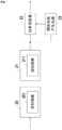
请参阅图2,其为本公开第一实施例的无线电能传输装置的电路结构示意图。如图2所示,本实施例的无线电能传输装置2包含位于发射侧的一功率发射电路20,以及位于接收侧的一功率接收电路21、一功率变换器22及一辅助电能产生电路23。Please refer to FIG. 2 , which is a schematic diagram of the circuit structure of the wireless power transmission device according to the first embodiment of the present disclosure. As shown in FIG. 2 , the wireless
功率发射电路20接收一输入电能,并发射一第一电能。功率接收电路21与功率发射电路20是隔离设置,且与功率发射电路20电磁耦合,功率接收电路21是用以接收功率发射电路20所发射的第一电能,并变换为一第二电能。功率变换器22电连接于功率接收电路21,其是依据第二电能来产生一输出电能,以提供输出电能至负载(未图示),其中该输出电能可为直流或者交流。辅助电能产生电路23的输入端电连接于功率接收电路21,以接收第二电能,并变换为一辅助电能,藉此提供辅助电能给无线电能传输装置2位于接收侧中的相关电路(未图示)。于某些实施例中,如图2所示,辅助电能产生电路23的输出端可电连接于功率变换器22,藉此辅助电能产生电路23可提供辅助电能至功率变换器22,例如提供辅助电能至功率变换器22的控制器(未图示)。另外,功率变换器22则接收第二电能,并转换而产生输出电能。The
在其它实施例中,功率发射电路20还包含一发射线圈201,功率接收电路21还包含一接收线圈211,接收线圈211与发射线圈201电磁耦合,因此当发射线圈201发射第一电能时,接收线圈211便接收发射线圈201所发射的第一电能,并变换为第二电能。In other embodiments, the
请参阅图3,并配合图2,其中图3为本公开第一实施例的适用于图2所示的无线电能传输装置的电能产生方法的流程图。本公开第一实施例的电能产生方法包含下列步骤:Please refer to FIG. 3 , together with FIG. 2 , wherein FIG. 3 is a flowchart of a power generation method applicable to the wireless power transmission device shown in FIG. 2 according to the first embodiment of the present disclosure. The electric energy generation method of the first embodiment of the present disclosure includes the following steps:
首先,控制功率发射电路20在被使能状态与被不使能状态之间切换(如步骤301所示)。其中,当功率发射电路20处于被不使能状态时,功率发射电路20停止运行,反之,当功率发射电路20处于使能状态时,功率发射电路20则运行。且于此步骤中,是控制功率发射电路20以一预设周期及一预设占空比在被使能状态与被不使能状态之间进行切换。First, control the
接着,于功率发射电路20处于被使能状态时,功率发射电路20发射第一电能,功率接收电路21接收第一电能并变换为第二电能(如步骤302所示)。Next, when the
接着,利用功率变换器22将第二电能变换为输出电能,并利用辅助电能产生电路23将第二电能变换为辅助电能(如步骤303所示),其中该输出电能可为直流或者交流。Next, use the
接着,判断功率接收电路21是否接收到第一电能(如步骤304所示)。于本实施例中,可由功率发射电路20来判断功率接收电路21是否接收到第一电能。Next, it is judged whether the
于步骤304中,若判断结果为否时,重新执行步骤301;若判断结果为是时,控制功率发射电路20持续处于被使能状态,藉此产生持续的辅助电能(如步骤305所示)。In
由上可知,本公开的电能产生方法控制功率发射电路20在被使能状态与被不使能状态之间切换,当功率发射电路20处于被使能状态时,功率接收电路21接收功率发射电路20所发射的第一电能并变换为第二电能,利用功率变换器22将第二电能变换为输出电能,其中该输出电能可为直流或者交流,并利用辅助电能产生电路23将第二电能变换为辅助电能,且在判断功率接收电路21能够接收到第一电能时,控制功率发射电路20持续处于被使能状态,藉此产生持续的辅助电能,因此,本公开的电能产生方法可在功率接收电路21能够接收到第一电能时,利用辅助电能产生电路23将功率接收电路21所输出的第二电能进行变换,以产生辅助电能,故无需以负载的功率电池或额外接入的电池作为辅助电能的能量来源,使得本公开的无线电能传输装置能够稳定地产生辅助电能,并减少人工维护的成本。此外,在判断功率接收电路21无法接收到第一电能时,控制功率发射电路20重新变为在被使能状态与被不使能状态之间持续切换,因此,当功率接收电路21与功率发射电路20无法进行无线电能传输时(例如相隔距离较远时),能够防止功率发射电路20持续处于被使能状态而造成浪费,藉此降低无线电能传输装置2的损耗。It can be seen from the above that the power generation method of the present disclosure controls the
请再参阅图3,并配合图2。由于在执行步骤302、303及304时,功率发射电路20皆须处于被使能状态,因此,在某些实施例中,于步骤301中,是控制功率发射电路20处于被使能状态的时间不小于执行步骤302、303及304所需的时间总和,藉此防止功率发射电路20处于被使能状态的时间长度不足以执行步骤302、303及304。Please refer to Figure 3 again and cooperate with Figure 2. Since the
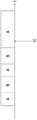
请参阅图4,并配合图3,其中图4为图3所示的电能产生方法中控制功率发射电路于被使能状态与被不使能状态之间切换的示意图。如图4所示,区域A为控制功率发射电路20处于被使能状态的时间,区域B为控制功率发射电路20处于被不使能状态之时间,横轴t为时间轴,而图4所示的时刻t1则示意为于图3所示的步骤304中,判断功率接收电路21接收到第一电能的时刻,因此,在时刻t1之前,是控制功率发射电路20于被使能状态与被不使能状态之间进行切换,而在时刻t1之后,则依照图3所示的步骤305,控制功率发射电路20持续处于被使能状态。Please refer to FIG. 4 together with FIG. 3 , wherein FIG. 4 is a schematic diagram of controlling the switching of the power transmission circuit between the enabled state and the disabled state in the power generation method shown in FIG. 3 . As shown in Figure 4, area A is the time when the control
请参阅图5,其为图2所示的无线电能传输装置的变化例的电路结构示意图。于此变化例中,无线电能传输装置5与图2所示的无线电能传输装置2的部分电路结构相似,故仅以相同符号标示来代表电路的结构相似而不再赘述。而与图2所示的无线电能传输装置2相比,此变化例的无线电能传输装置5还包含位于发射侧的一第一无线通信电路54,以及位于接收侧的一第二无线通信电路55。第二无线通信电路55电连接于辅助电能产生电路23的输出端,以接收辅助电能而运行,并于运行时通过射频方式发射一无线通信信号,第一无线通信电路54电连接于功率发射电路20,并通过相应的射频方式接收第二无线通信电路55所输出的无线通信信号,且传输至功率发射电路20,使功率发射电路20通过无线通信信号来判断功率接收电路21是否接收到第一电能。其中,射频方式可为蓝牙或wifi,但不限于此。Please refer to FIG. 5 , which is a schematic circuit structure diagram of a modification example of the wireless power transmission device shown in FIG. 2 . In this variation example, the wireless
请参阅图6,并搭配图3及图5。其中图6为图3所示的电能产生方法的变化例的流程图,且图6所示的电能产生方法适用于图5所示的无线电能传输装置5。于此变化例中,电能产生方法与图3所示的电能产生方法的部分步骤相似,故仅以相同符号标示来代表步骤相似而不再赘述。而与图2所示的电能产生方法相比,此变化例的电能产生方法中的步骤304还包含下列子步骤:Please refer to Figure 6 together with Figure 3 and Figure 5. 6 is a flow chart of a variation example of the power generation method shown in FIG. 3 , and the power generation method shown in FIG. 6 is applicable to the wireless
首先,提供辅助电能至第二无线通信电路55,使第二无线通信电路55发射无线通信信号(如步骤601所示)。First, provide auxiliary power to the second
接着,通过判断第一无线通信电路54是否接收到该无线通信信号来判断功率接收电路21是否接收到第一电能(如步骤602所示)。Next, it is judged whether the
其中,当步骤602的判断结果为是时,即可得知功率接收电路21已接收到第一电能才能使辅助电能产生电路23产生辅助电能,并供电至第二无线通信电路55,以驱动第二无线通信电路55运行而发出无线通信信号,故当步骤602的判断结果为是时,便执行步骤305;当步骤602的判断结果为否时,即可得知功率接收电路21并无接收到第一电能,因而使辅助电能产生电路23无法产生辅助电能,导致第二无线通信电路55无法运行而发出无线通信信号,故当步骤602的判断结果为否时,便重新执行步骤301。Wherein, when the judgment result of
此外,在一些实施例中,于步骤601中,第二无线通信电路55利用一射频方式发射无线通信信号,而于步骤602中,是利用该射频方式判断第一无线通信电路54是否接收到该无线通信信号。In addition, in some embodiments, in
请参阅图7,并配合图2,其中图7为本公开第二实施例的适用于图2所示的无线电能传输装置的电能产生方法的流程图。本公开第二实施例的电能产生方法包含下列步骤:Please refer to FIG. 7 , together with FIG. 2 , wherein FIG. 7 is a flowchart of a power generation method applicable to the wireless power transmission device shown in FIG. 2 according to the second embodiment of the present disclosure. The electric energy generation method of the second embodiment of the present disclosure includes the following steps:
首先,控制功率发射电路20处于被使能状态,并发射第一电能,且控制功率接收电路21接收第一电能并变换为第二电能(如步骤701所示)。其中,当功率发射电路20处于被使能状态时,功率发射电路20接收输入电能并正常运行。Firstly, control the
接着,利用功率变换器22将第二电能变换为输出电能,并利用辅助电能产生电路23将第二电能变换为辅助电能(如步骤702所示),其中该输出电能可为直流或者交流。Next, use the
于此实施例中,是因处于无线电能传输装置2可持续进行无线电能传输,即功率接收电路21可持续接收功率发射电路20所发射的第一电能的情况,故可直接控制功率发射电路20持续处于被使能状态,以产生持续的辅助电能。In this embodiment, because the wireless
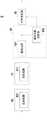
请参阅图8,其为本公开第三实施例的无线电能传输装置的电路结构示意图。如图8所示,本实施例的无线电能传输装置8包含一功率发射电路80、一功率接收电路81、一功率变换器82及一辅助电能产生电路83。Please refer to FIG. 8 , which is a schematic circuit diagram of a wireless power transmission device according to a third embodiment of the present disclosure. As shown in FIG. 8 , the wireless
功率发射电路80接收一输入电能,并发射一第一电能,功率接收电路81与功率发射电路80电磁耦合,藉此接收功率发射电路80所发射的第一电能,并变换为一第二电能。The
辅助电能产生电路83,是用以将功率接收电路81所输出的第二电能变换为一辅助电能,且包含一整流电路831及一辅助电能变换器832。整流电路831电连接于功率接收电路81的输出端,以接收第二电能并整流为一第三电能,功率变换器82电连接于整流电路831,以接收第三电能,并变换为一输出电能,其中该输出电能可为直流或者交流。辅助电能变换器832的输入端电连接于整流电路831及功率变换器82,以接收第三电能并变换为辅助电能,且辅助电能变换器832的输出端电连接于功率变换器82,以传输辅助电能至功率变换器82。其中,辅助电能变换器832可为线性稳压电路,也可为隔离式或非隔离式的电力电子开关电路,但不限于此。The auxiliary electric
在某些实施例中,功率发射电路80还包含一发射线圈801,功率接收电路81还包含一接收线圈811,发射线圈801发射第一电能,接收线圈811与发射线圈801电磁耦合,藉此接收发射线圈801所发射的第一电能,并变换为第二电能。In some embodiments, the
请参阅图9,其为本公开第四实施例的无线电能传输装置的电路结构示意图。如图9所示,本实施例的无线电能传输装置9包含一功率发射电路90、一功率接收电路91、一功率变换器92及一辅助电能产生电路93。Please refer to FIG. 9 , which is a schematic circuit diagram of a wireless power transmission device according to a fourth embodiment of the present disclosure. As shown in FIG. 9 , the wireless
功率发射电路90接收一输入电能,并发射第一电能,功率接收电路91与功率发射电路90电磁耦合,藉此接收功率发射电路90所发射的第一电能,并变换为第二电能。功率变换器92电连接于功率接收电路91,以将功率接收电路91所输出的第二电能变换为输出电能,其中该输出电能可为直流或交流。The
辅助电能产生电路93,是用以将功率接收电路91所输出的第二电能变换为一辅助电能,且包含一整流电路931及一辅助电能变换器932。整流电路931电连接于功率接收电路91的输出端,以接收第二电能并整流为一第三电能。辅助电能变换器932电连接于整流电路931的输出端及功率变换器92,以接收第三电能并变换为辅助电能,且传输辅助电能至功率变换器92。其中,辅助电能变换器932可为线性稳压电路,也可为隔离式或非隔离式的电力电子开关电路,但不限于此。The auxiliary electric
此外,在某些实施例中,功率发射电路90还包含一发射线圈901,功率接收电路91还包含一接收线圈911,发射线圈901发射第一电能,接收线圈911与发射线圈901电磁耦合,藉此接收发射线圈901所发射的第一电能,并变换为第二电能。In addition, in some embodiments, the
综上所述,本公开的电能产生方法及其适用的无线电能传输装置通过控制功率接收电路接收功率发射电路所发射的电能,并控制辅助电能产生电路将功率接收电路所接收的电能变换为辅助电能,产生无线电能传输装置的接收侧的辅助电能,故辅助电能的能量来源为无线电能传输装置的功率发射电路所接收的输入电能,而无需如现有技术以无线电能传输装置的接收侧的电池作为能量来源,因此,本公开的电能产生方法及其适用的无线电能传输装置可降低产生无线电能传输装置的接收侧的辅助电源的成本。此外,本公开的电能产生方法及其适用的无线电能传输装置可控制功率发射电路在被使能状态与被不使能状态之间切换,并于判断功率接收电路确实接收到功率发射电路所发射的电能时,控制功率发射电路持续处于被使能状态,故于功率接收电路无法接收到功率发射电路所发射的电能时,能够防止功率发射电路持续处于被使能状态而造成浪费,藉此降低无线电能传输装置的损耗。In summary, the power generation method of the present disclosure and its applicable wireless power transmission device control the power receiving circuit to receive the power transmitted by the power transmitting circuit, and control the auxiliary power generating circuit to convert the power received by the power receiving circuit into auxiliary The electric energy generates auxiliary electric energy on the receiving side of the wireless energy transmission device, so the energy source of the auxiliary electric energy is the input electric energy received by the power transmission circuit of the wireless energy transmission device, without using the receiving side of the wireless energy transmission device as in the prior art The battery is used as the energy source, therefore, the electric energy generation method of the present disclosure and the wireless power transmission device applicable thereto can reduce the cost of generating auxiliary power for the receiving side of the wireless power transmission device. In addition, the power generation method of the present disclosure and its applicable wireless power transmission device can control the power transmitting circuit to switch between the enabled state and the disabled state, and determine that the power receiving circuit has indeed received the power transmitted by the power transmitting circuit. When the power transmission circuit is in the enabled state continuously, the power receiving circuit cannot receive the electric energy transmitted by the power transmission circuit, which can prevent the power transmission circuit from being continuously enabled and cause waste, thereby reducing Loss of wireless power transfer devices.
须注意,上述仅是为说明本公开而提出的优选实施例,本公开不限于所述的实施例,本公开的范围由如附专利申请范围决定。且本公开得由熟习此技术的人士任施匠思而为诸般修饰,然皆不脱如附专利申请范围所欲保护者。It should be noted that the above-mentioned preferred embodiments are only proposed to illustrate the present disclosure, and the present disclosure is not limited to the described embodiments, and the scope of the present disclosure is determined by the scope of the attached patent application. And this disclosure can be modified in various ways by those who are familiar with this technology, but they are all within the intended protection of the scope of the attached patent application.
Claims (15)
Priority Applications (2)
| Application Number | Priority Date | Filing Date | Title |
|---|---|---|---|
| CN201710818260.3ACN109494889B (en) | 2017-09-12 | 2017-09-12 | Electric energy generation method and wireless energy transmission device applicable thereto |
| US16/013,660US10923950B2 (en) | 2017-09-12 | 2018-06-20 | Power generating method and wireless power transmission device therefor |
Applications Claiming Priority (1)
| Application Number | Priority Date | Filing Date | Title |
|---|---|---|---|
| CN201710818260.3ACN109494889B (en) | 2017-09-12 | 2017-09-12 | Electric energy generation method and wireless energy transmission device applicable thereto |
Publications (2)
| Publication Number | Publication Date |
|---|---|
| CN109494889A CN109494889A (en) | 2019-03-19 |
| CN109494889Btrue CN109494889B (en) | 2022-12-20 |
Family
ID=65631675
Family Applications (1)
| Application Number | Title | Priority Date | Filing Date |
|---|---|---|---|
| CN201710818260.3AActiveCN109494889B (en) | 2017-09-12 | 2017-09-12 | Electric energy generation method and wireless energy transmission device applicable thereto |
Country Status (2)
| Country | Link |
|---|---|
| US (1) | US10923950B2 (en) |
| CN (1) | CN109494889B (en) |
Families Citing this family (4)
| Publication number | Priority date | Publication date | Assignee | Title |
|---|---|---|---|---|
| CN111559268B (en)* | 2020-07-15 | 2020-10-16 | 北京有感科技有限责任公司 | Wireless charging system |
| CN116018743A (en)* | 2020-08-14 | 2023-04-25 | 思睿逻辑国际半导体有限公司 | Wireless power architecture with series coupled power converters |
| CN114696875B (en) | 2022-03-24 | 2024-07-02 | 台达电子企业管理(上海)有限公司 | Wireless communication device and control method thereof |
| CN114567089A (en)* | 2022-03-24 | 2022-05-31 | 台达电子企业管理(上海)有限公司 | Wireless charging system and control method thereof |
Citations (1)
| Publication number | Priority date | Publication date | Assignee | Title |
|---|---|---|---|---|
| CN106300698A (en)* | 2016-09-05 | 2017-01-04 | 青岛鲁渝能源科技有限公司 | Wireless power transfer system and wireless power transfer control method |
Family Cites Families (10)
| Publication number | Priority date | Publication date | Assignee | Title |
|---|---|---|---|---|
| US8169185B2 (en)* | 2006-01-31 | 2012-05-01 | Mojo Mobility, Inc. | System and method for inductive charging of portable devices |
| US20090284369A1 (en)* | 2008-05-13 | 2009-11-19 | Qualcomm Incorporated | Transmit power control for a wireless charging system |
| US10523276B2 (en)* | 2011-08-16 | 2019-12-31 | Qualcomm Incorporated | Wireless power receiver with multiple receiver coils |
| CN204068438U (en) | 2014-07-04 | 2014-12-31 | 国家电网公司 | A fault indicator power supply with a wireless communication module |
| JP6651711B2 (en)* | 2015-05-13 | 2020-02-19 | セイコーエプソン株式会社 | Control device, electronic equipment and contactless power transmission system |
| CN105262514B (en)* | 2015-09-29 | 2018-03-02 | 中国科学技术大学 | The exchange method of receiving terminal and transmitting terminal in radiant type radio energy transmission system |
| CN105576845A (en) | 2016-02-25 | 2016-05-11 | 苏州立感电子科技有限公司 | Wireless power supply device, wireless charging system and wireless charging method |
| TWI679826B (en)* | 2016-06-10 | 2019-12-11 | 美商歐西亞股份有限公司 | Method and apparatus for wireless power transmission for near and far field applications |
| CN106451704A (en)* | 2016-12-05 | 2017-02-22 | 青岛鲁渝能源科技有限公司 | Wireless charging system and wireless charging method applied to mobile terminal |
| CN107124047B (en)* | 2017-06-27 | 2023-12-29 | 青岛鲁渝能源科技有限公司 | Wireless power transmission system and radio frequency communication method thereof |
- 2017
- 2017-09-12CNCN201710818260.3Apatent/CN109494889B/enactiveActive
- 2018
- 2018-06-20USUS16/013,660patent/US10923950B2/enactiveActive
Patent Citations (1)
| Publication number | Priority date | Publication date | Assignee | Title |
|---|---|---|---|---|
| CN106300698A (en)* | 2016-09-05 | 2017-01-04 | 青岛鲁渝能源科技有限公司 | Wireless power transfer system and wireless power transfer control method |
Also Published As
| Publication number | Publication date |
|---|---|
| US10923950B2 (en) | 2021-02-16 |
| CN109494889A (en) | 2019-03-19 |
| US20190081510A1 (en) | 2019-03-14 |
Similar Documents
| Publication | Publication Date | Title |
|---|---|---|
| US8314513B2 (en) | Power transmission control device, power transmission device, power reception control device, power reception device, electronic apparatus, and contactless power transmission system | |
| CN109494889B (en) | Electric energy generation method and wireless energy transmission device applicable thereto | |
| US9729204B2 (en) | Device and system for power transmission | |
| JP5853889B2 (en) | Power receiving device and power transmission system | |
| US20130313911A1 (en) | Power supply apparatus and power control method thereof | |
| CN109510466A (en) | System and method for starting high density isolation DC/DC electric power converter | |
| JP2013198260A (en) | Power transmission system | |
| CN109094389A (en) | Wireless charging receiver, electric car and wireless charging system | |
| JP2013215065A (en) | Power transmission system | |
| CN104953682A (en) | Circuit with wireless charging transmitting function and wireless charging receiving function and device thereof | |
| CN104617646A (en) | An intelligent wireless charging device based on ZVS self-excited magnetic resonance | |
| CN109075615B (en) | System and apparatus for inductive charging of a handheld device | |
| US9787104B2 (en) | Power transmission system | |
| EP3026786B1 (en) | Power-transfer system | |
| EP3131176A1 (en) | Power transmission device and non-contact power transmission apparatus | |
| JP5772687B2 (en) | Power transmission system, power transmission device and power reception device, charging facility, and electric vehicle | |
| CN113196613B (en) | Contactless power supply system and power receiving device | |
| KR102773408B1 (en) | Wireless power transfer power control techniques | |
| CN112366760A (en) | Charging circuit, charging method and wireless transmitting equipment | |
| JP2018170820A (en) | Wireless power transmission apparatus and wireless power transmission system | |
| CN108092420B (en) | Control method of electric energy receiving end and wireless electric energy transmission device | |
| JP2015089187A (en) | Non-contact power transmission device, power transmission apparatus and power reception apparatus | |
| JP2017005841A (en) | Power transmission apparatus | |
| CN110718970A (en) | Power transmitting device, power receiving device, and power transmission system | |
| KR102086859B1 (en) | Hybrid type wireles power receiving device, method of controlling wireless power signal in hybrid type wireles power receiving device, and magnetic resonance type wireless power receiving device related to the same |
Legal Events
| Date | Code | Title | Description |
|---|---|---|---|
| PB01 | Publication | ||
| PB01 | Publication | ||
| SE01 | Entry into force of request for substantive examination | ||
| SE01 | Entry into force of request for substantive examination | ||
| GR01 | Patent grant | ||
| GR01 | Patent grant |