CN109491244B - A Fault Diagnosis Method of UAV Formation System Based on Sliding Mode Observer - Google Patents
A Fault Diagnosis Method of UAV Formation System Based on Sliding Mode ObserverDownload PDFInfo
- Publication number
- CN109491244B CN109491244BCN201710839720.0ACN201710839720ACN109491244BCN 109491244 BCN109491244 BCN 109491244BCN 201710839720 ACN201710839720 ACN 201710839720ACN 109491244 BCN109491244 BCN 109491244B
- Authority
- CN
- China
- Prior art keywords
- sliding mode
- matrix
- observer
- fault
- aerial vehicle
- Prior art date
- Legal status (The legal status is an assumption and is not a legal conclusion. Google has not performed a legal analysis and makes no representation as to the accuracy of the status listed.)
- Expired - Fee Related
Links
Images


Classifications
- G—PHYSICS
- G05—CONTROLLING; REGULATING
- G05B—CONTROL OR REGULATING SYSTEMS IN GENERAL; FUNCTIONAL ELEMENTS OF SUCH SYSTEMS; MONITORING OR TESTING ARRANGEMENTS FOR SUCH SYSTEMS OR ELEMENTS
- G05B13/00—Adaptive control systems, i.e. systems automatically adjusting themselves to have a performance which is optimum according to some preassigned criterion
- G05B13/02—Adaptive control systems, i.e. systems automatically adjusting themselves to have a performance which is optimum according to some preassigned criterion electric
- G05B13/04—Adaptive control systems, i.e. systems automatically adjusting themselves to have a performance which is optimum according to some preassigned criterion electric involving the use of models or simulators
- G05B13/042—Adaptive control systems, i.e. systems automatically adjusting themselves to have a performance which is optimum according to some preassigned criterion electric involving the use of models or simulators in which a parameter or coefficient is automatically adjusted to optimise the performance
Landscapes
- Engineering & Computer Science (AREA)
- Health & Medical Sciences (AREA)
- Artificial Intelligence (AREA)
- Computer Vision & Pattern Recognition (AREA)
- Evolutionary Computation (AREA)
- Medical Informatics (AREA)
- Software Systems (AREA)
- Physics & Mathematics (AREA)
- General Physics & Mathematics (AREA)
- Automation & Control Theory (AREA)
- Feedback Control In General (AREA)
Abstract
Translated fromChinese
Description
Translated fromChinese技术领域technical field
本发明涉及一种基于滑模观测器的无人机编队系统的故障诊断方法,属于无人机编队故障诊断领域。The invention relates to a fault diagnosis method for an unmanned aerial vehicle formation system based on a sliding mode observer, and belongs to the field of unmanned aerial vehicle formation fault diagnosis.
背景技术Background technique
随着物联网技术的飞速发展,无人机编队这一物联网应用被广泛应用于军用和民用领域,受到了越来越多人的关注。但随着整个编队中无人机架数的提升,故障发生的可能性和故障引发后果的严重性都大大提升了,所以相关的无人机编队的故障诊断方法也显得格外重要。With the rapid development of Internet of Things technology, the Internet of Things application of drone formation is widely used in military and civilian fields, and has attracted more and more people's attention. However, with the increase in the number of UAVs in the entire formation, the possibility of failures and the severity of the consequences of failures have greatly increased, so the relevant UAV formation fault diagnosis methods are also particularly important.
在过去的二三十年间,飞控系统故障诊断的方法日趋成熟,但这些方法大多都是针对集中式系统,不适用于存在信息交互的无人机编队系统。而现有的关于物联网环境下的多智能体方面的优秀成果中,又多是针对于系统控制或是优化方面的研究,对本发明研究的对象无人机编队系统的故障诊断更是不多见。现阶段,国内外关于多智能体故障诊断的研究成果大多数都只是致力于于故障的监测和隔离,而仅仅依靠这些的话对于现代大型无人机编队的风险管控显然是不够的,这也就突显出了实时在线的故障估计的重要性。In the past two or three decades, the methods of flight control system fault diagnosis have become more and more mature, but most of these methods are aimed at centralized systems and are not suitable for UAV formation systems with information interaction. However, most of the existing outstanding achievements on multi-agents in the Internet of Things environment are aimed at the research on system control or optimization, and there are not many fault diagnosis for the UAV formation system, which is the object of the present invention. See. At this stage, most of the research results on multi-agent fault diagnosis at home and abroad are only dedicated to fault monitoring and isolation, and relying solely on these is obviously not enough for the risk management and control of modern large-scale UAV formations, which also The importance of real-time online fault estimation is highlighted.
在为数不多的物联网环境下的多智能体故障估计成果中,又多是仅仅只考虑了无向图的网络拓扑结构,而且对象也只是简单的一阶线性系统,大大降低了实用性。相比于无向图,有向图的限制虽然更多,但也更符合实际情况,更有研究价值,而且实际的非线性无人机编队系统也比一般的简单的线性系统更有意义。所以本发明针对于有向图网络拓扑结构描述下的非线性无人机编队系统设计了一种分布式自适应滑模观测器来进行故障估计。本发明的主要创新点在于:(1)采用了更严谨的有向图的网络拓扑结构,且对象为存在信息交互,且具有扰动和非线性等特征的无人机编队系统;(2)对于每一个单独的无人机设计了基于相对输出估计误差的滑模观测器,并引入自适应律来克服故障上界未知的情况;(3)所设计观测器的所有参数都可以通过线性矩阵不等式工具箱计算得到,且可以通过寻优找到可以克服的最大非线性系数。In the few multi-agent fault estimation results in the Internet of Things environment, most of them only consider the network topology of undirected graphs, and the objects are only simple first-order linear systems, which greatly reduces the practicability. Compared with undirected graphs, directed graphs have more limitations, but they are more in line with the actual situation and have more research value, and the actual nonlinear UAV formation system is also more meaningful than the general simple linear system. Therefore, the present invention designs a distributed adaptive sliding mode observer for fault estimation for the nonlinear UAV formation system described by the directed graph network topology. The main innovations of the present invention are: (1) a more rigorous directed graph network topology is adopted, and the object is a UAV formation system with information interaction and features such as disturbance and nonlinearity; (2) for For each individual UAV, a sliding-mode observer based on relative output estimation error is designed, and an adaptive law is introduced to overcome the situation that the upper bound of the fault is unknown; (3) All parameters of the designed observer can be obtained by the linear matrix inequality The toolbox calculates and can be optimized to find the largest nonlinear coefficient that can be overcome.
发明内容SUMMARY OF THE INVENTION
为避免以上现有技术的不足,本发明提出一种基于滑模观测器的无人机编队故障诊断方法,以解决对无人机编队系统进行在线故障估计的问题。In order to avoid the above deficiencies in the prior art, the present invention proposes a UAV formation fault diagnosis method based on a sliding mode observer, so as to solve the problem of online fault estimation for the UAV formation system.
本发明为实现上述目的,采用如下技术方案:The present invention adopts following technical scheme for realizing the above-mentioned purpose:
1)对含有未知上界的执行器故障的单架无人机建立非线性模型;1) Build a nonlinear model for a single UAV with actuator faults with unknown upper bounds;
2)设计相应的滑模观测器,并引入基于有向图网络拓扑结构描述下的相对输出误差来表征个体信息的交互;2) Design the corresponding sliding mode observer, and introduce the relative output error based on the topological description of the directed graph network to characterize the interaction of individual information;
3)基于单架无人机的状态空间方程和观测器结构,构造全局误差系统;3) Construct a global error system based on the state space equation and observer structure of a single UAV;
4)求解全局滑模稳定条件和到达条件;4) Solve the global sliding mode stability condition and arrival condition;
5)利用线性矩阵不等式工具箱解算待设计量;5) Use the linear matrix inequality toolbox to solve the quantity to be designed;
6)根据等效控制输出误差注入原理进行故障估计。6) Carry out fault estimation according to the principle of equivalent control output error injection.
进一步,步骤1)对含有未知上界的执行器故障的单架无人机建立非线性模型具体为:Further, step 1) establishing a nonlinear model for a single UAV containing an actuator fault with an unknown upper bound is specifically:
101)考虑有向图网络拓扑结构下的N架僚机和1架长机组成的无人机编队系统,其中任一无人机在执行器故障的情况下的状态空间模型如下所示:101) Consider a UAV formation system composed of N wingmen and one leader under the directed graph network topology, and the state space model of any UAV in the case of actuator failure is as follows:

其中,i=1,2,...,N,


进一步,步骤2)设计相应的滑模观测器,并引入基于有向图网络拓扑结构描述下的相对输出误差来表征个体信息的交互具体为:Further, step 2) design a corresponding sliding mode observer, and introduce the relative output error based on the description of the directed graph network topology to characterize the interaction of individual information as follows:
201)设计存在基于有向图网络拓扑结构描述下的相对输出误差的自适应滑模观测器:201) Design an adaptive sliding mode observer based on the relative output error described by the directed graph network topology:

其中,


其中,


此分布式滑模观测器不同于传统的集中式结构观测器或是拥有理想化通讯过程,即没有误差的通讯,在滑模观测器中加入相对输出估计误差,且该误差是基于整个无人机编队的网络拓扑结构实时得到,更贴合实际。This distributed sliding mode observer is different from the traditional centralized structure observer or has an idealized communication process, that is, communication without error. The relative output estimation error is added to the sliding mode observer, and the error is based on the entire unmanned The network topology of the aircraft formation is obtained in real time, which is more realistic.
进一步,步骤3)基于单架无人机的状态空间方程和观测器结构,构造全局误差系统具体为:Further, step 3) based on the state space equation and observer structure of a single UAV, construct a global error system specifically:
301)为了从全局的角度考虑执行器故障估计的问题,定义如下全局变量:301) In order to consider the problem of actuator fault estimation from a global perspective, the following global variables are defined:


eg(t)=[eg1(t)T,eg2(t)T,...,egN(t)T]Teg (t)=[eg1 (t)T , eg2 (t)T , ..., egN (t)T ]T


302)考虑单一无人机的状态估计误差方程:302) Consider the state estimation error equation of a single UAV:

其中,

其中,符号

进一步,步骤4)求解全局滑模稳定条件和到达条件具体为:Further, step 4) solving the global sliding mode stability conditions and reaching conditions is specifically:
401)求解全局滑模稳定条件。401) Solve the global sliding mode stability condition.
定义变量μi(t)=α+ρi(t),则相应的全局变量为

考虑如下Lyapunov函数:Consider the following Lyapunov function:

其中


由式(3)可得:From formula (3), we can get:

至此可以发现,式(9)恒小于0,将式(9)再代入回式(8)可得:So far, it can be found that the formula (9) is always less than 0, and the formula (9) is substituted into the formula (8) to obtain:

其中,

由式(10)可以看出,当R>0时,状态误差收敛,则有It can be seen from equation (10) that when R>0, the state error converges, then there is

由式(12)可知,当


其中,δ为正数。所设计的滑模观测器可以保证状态估计误差最终有界稳定,稳定条件为:where δ is a positive number. The designed sliding mode observer can ensure the final bounded stability of the state estimation error, and the stability conditions are:

402)求解全局滑模到达条件。402) Solve the global sliding mode arrival condition.
接下来将推导滑模运动可以克服故障上界未知和干扰的影响,在有限时间内到达滑模面S={ey(t):ey(t)=0}上的条件。Next, it will be deduced that the sliding mode motion can overcome the influence of the unknown upper bound of the fault and the influence of disturbance, and reach the condition on the sliding mode surface S={ey (t):ey (t)=0} in a finite time.
定义一个线性变换矩阵


为方便表达,定义:For convenience, define:


于是式(15)可以转换为如下形式:So equation (15) can be transformed into the following form:

考虑如下Lyapunov函数:Consider the following Lyapunov function:

将式(19)对时间求导可得:Taking the time derivative of equation (19), we can get:

由式(13)和式(18)可得出,当From equations (13) and (18), it can be obtained that when

时,有
进一步,步骤5)利用线性矩阵不等式工具箱解算待设计量具体为:Further, step 5) utilizes the linear matrix inequality toolbox to solve the quantity to be designed specifically:
501)根据式(14)利用MATLAB中LMI工具箱求解P,Y,γ。501) According to formula (14), use the LMI toolbox in MATLAB to solve P, Y, γ.
502)求解观测器增益K=P-1Y。502) Solve the observer gain K=P-1 Y.
503)根据式(13)与式(19)求解ρ0。503) Solve ρ0 according to formula (13) and formula (19).
504)根据502)中求得的K与503)中求得的ρ0建立滑模观测器。504) Establish a sliding mode observer according to K obtained in 502) and ρ0 obtained in 503).
进一步,步骤6)根据等效控制输出误差注入原理进行故障估计具体为:Further, step 6) according to the principle of equivalent control output error injection, the fault estimation is specifically:
当滑模运动到达滑模面时,When the sliding mode motion reaches the sliding mode surface,

将式(20)代入式(16),可得Substituting equation (20) into equation (16), we can get

再由步骤4)中稳定条件与滑模到达条件可知Then it can be known from the stable condition and the sliding mode arrival condition in step 4)

按照常理,未知扰动等不确定因素往往比故障信号小的多,所以通过等效控制输出误差注入原理,故障估计可以表示为:According to common sense, uncertain factors such as unknown disturbance are often much smaller than the fault signal, so through the principle of equivalent control output error injection, the fault estimation can be expressed as:

有益效果:Beneficial effects:
(1)采用了更严谨的有向图的网络拓扑结构,且对象为存在信息交互,且具有扰动和非线性等特征的无人机编队系统;(1) A more rigorous directed graph network topology is adopted, and the object is a UAV formation system with information interaction and features such as disturbance and nonlinearity;
(2)对于每一个单独的无人机设计了基于相对输出估计误差的滑模观测器,并引入自适应律来克服故障上界未知的情况;(2) For each individual UAV, a sliding mode observer based on relative output estimation error is designed, and an adaptive law is introduced to overcome the situation that the upper bound of the fault is unknown;
(3)所设计观测器的所有参数都可以通过线性矩阵不等式工具箱计算得到,且可以通过寻优找到可以克服的最大非线性系数。(3) All the parameters of the designed observer can be calculated by the linear matrix inequality toolbox, and the maximum nonlinear coefficient that can be overcome can be found through optimization.
(4)故障估计速度快,精确度高,抗干扰能力强。(4) The fault estimation speed is fast, the accuracy is high, and the anti-interference ability is strong.
附图说明Description of drawings
图1是本发明的无人机长僚机编队与通信结构;Fig. 1 is the UAV chief wingman formation and communication structure of the present invention;
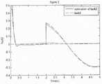
图2是无人机1利用本发明中提供的方法进行故障估计的效果图;Fig. 2 is the effect diagram that the unmanned
图3是无人机2利用本发明中提供的方法进行故障估计的效果图;Fig. 3 is the effect diagram that
图4是无人机3利用本发明中提供的方法进行故障估计的效果图;Fig. 4 is the effect diagram that
图5是无人机4利用本发明中提供的方法进行故障估计的效果图;Fig. 5 is the effect diagram that the unmanned
图6是无人机5利用本发明中提供的方法进行故障估计的效果图;Fig. 6 is the effect diagram that the unmanned
具体实施方式Detailed ways
下面结合附图和具体实施例,进一步阐明本发明的技术方案和优点。显然,所描述的实施例是本发明的一部分实施例,而不是全部。基于本发明,本领域技术人员对本发明非创造性的等价修改均属于本发明保护范围。The technical solutions and advantages of the present invention are further explained below with reference to the accompanying drawings and specific embodiments. Obviously, the described embodiments are some, but not all, of the embodiments of the present invention. Based on the present invention, non-creative equivalent modifications of the present invention by those skilled in the art all belong to the protection scope of the present invention.
实施例Example
1.如图1所示,考虑有向图网络拓扑结构下的5架僚机和1架长机组成的无人机编队系统,其中任一无人机在执行器故障的情况下的状态空间模型建模为如下所示:1. As shown in Figure 1, consider the UAV formation system composed of 5 wingmen and 1 leader under the directed graph network topology, and the state space model of any UAV in the case of actuator failure Modeled as follows:

其中,i=1,2,...,5,


2.设计存在基于有向图网络拓扑结构描述下的相对输出误差的自适应滑模观测器有如下形式:2. The design of an adaptive sliding mode observer with relative output error based on a directed graph network topology description has the following form:

其中,


其中,
3.基于单架无人机的状态空间方程和观测器结构,构造全局误差系统。3. Based on the state space equation and observer structure of a single UAV, construct a global error system.
31.为了从全局的角度考虑执行器故障估计的问题,定义如下全局变量:31. In order to consider the problem of actuator fault estimation from a global perspective, the following global variables are defined:


eg(t)=[eg1(t)T,eg2(t)T,...,egN(t)T]Teg (t)=[eg1 (t)T , eg2 (t)T , ..., egN (t)T ]T


32.考虑单一无人机的状态估计误差方程:32. Consider the state estimation error equation for a single UAV:

其中,

其中,符号

4.求解全局滑模稳定条件和到达条件,并设计滑模变结构项。4. Solve the global sliding mode stability conditions and arrival conditions, and design sliding mode variable structure terms.
41.设计滑模变结构项。41. Design sliding mode variable structure term.
定义变量μi(t)=α+ρi(t),则相应的全局变量为
为了克服故障上界未知情况,考虑如下Lyapunov函数:To overcome the unknown upper bound of the fault, consider the following Lyapunov function:

其中


为设计滑模变结构项,只取


为了所取部分项恒小于0,则滑模变结构项设计为:In order to take part of the term always less than 0, the sliding mode variable structure term is designed as:

其中,

42.求解滑模稳定条件,取

其中,

要使

由此可知,要使


其中,δ为正数。所设计的滑模观测器可以保证状态估计误差最终有界稳定,稳定条件为:where δ is a positive number. The designed sliding mode observer can ensure the final bounded stability of the state estimation error, and the stability conditions are:

43.求解全局滑模到达条件。43. Solve the global sliding mode arrival condition.
定义滑模面为S={ey(t):ey(t)=0}。The sliding mode surface is defined as S={ey (t):ey (t)=0}.
定义一个线性变换矩阵


为方便表达,定义:For convenience, define:


于是线性变换后的全局状态估计误差方程可以转换为如下形式:So the linearly transformed global state estimation error equation can be transformed into the following form:

考虑如下Lyapunov函数:Consider the following Lyapunov function:

将

为使

所以状态估计误差的滑模运动可以在有限时间内到达滑模面S={ey(t):ey(t)=0}。So the sliding mode motion of the state estimation error can reach the sliding mode surface S={ey (t):ey (t)=0} in a finite time.
5.利用线性矩阵不等式工具箱解算待设计量。5. Use the linear matrix inequality toolbox to solve the quantity to be designed.
51.根据滑模稳定条件利用MATLAB中LMI工具箱求解P,Y,γ。51. According to the sliding mode stability condition, use the LMI toolbox in MATLAB to solve P, Y, γ.
52.求解观测器增益K=P-1Y。52. Solve for the observer gain K = P-1 Y.
53.根据滑模到达条件求解ρ0。53. Solve for ρ0 according to the sliding mode arrival condition.
54.根据求得的K与ρ0建立滑模观测器。54. Establish a sliding mode observer according to the obtained K and ρ0 .
步骤6)根据等效控制输出误差注入原理进行故障估计。Step 6) Perform fault estimation according to the principle of equivalent control output error injection.
当滑模运动到达滑模面时,When the sliding mode motion reaches the sliding mode surface,

将其代入线性变换后的全局状态估计误差方程,可得Substituting it into the global state estimation error equation after linear transformation, we can get

再由稳定条件与滑模到达条件可知Then it can be known from the stable condition and the sliding mode arrival condition

按照常理,未知扰动等不确定因素往往比故障信号小的多,所以通过等效控制输出误差注入原理,故障估计可以表示为:According to common sense, uncertain factors such as unknown disturbance are often much smaller than the fault signal, so through the principle of equivalent control output error injection, the fault estimation can be expressed as:

本实施例中使用的无人机横侧向模型参数如下所示:The UAV lateral and lateral model parameters used in this example are as follows:

按图1中的编队方式得到的拉普拉斯矩阵与标定矩阵如下所示:The Laplacian matrix and calibration matrix obtained by the formation method in Figure 1 are as follows:

在第一通道选择非线性项gi(xi(t))=-6.3541sin(xi4(t)),其它通道为0。干扰设为φi(t)=0.05cos(7t),考虑执行器故障发生在输入通道,即E=B。在MATLAB中运用LMI工具箱,按步骤5)可以解得:The nonlinear term gi (xi (t))=-6.3541 sin(xi4 (t)) is selected in the first channel, and 0 in other channels. The interference is set to φi (t)=0.05cos(7t), considering that the actuator failure occurs in the input channel, that is, E=B. Using the LMI toolbox in MATLAB, according to step 5) can be solved:


在实施例过程中,步长取为0.001s,各系统初始状态各不相同,给定5架无人机故障分别为:In the process of the embodiment, the step length is taken as 0.001s, and the initial states of each system are different. The faults of the given five UAVs are:


f51(t)=0.3sin(t),f52(t)=0f51 (t)=0.3 sin(t), f52 (t)=0
具体实施例结果如图2-图6所示:The results of the specific embodiment are shown in Figure 2-Figure 6:
从本实施例结果可以清晰的看出,图2-图6中每一个无人机节点的故障估计误差都非常小,只用了大约0.5秒的时间就从初始状态跟踪上了故障。在面对突然的故障时,从图2可以看出,常值故障的跟踪非常好,而对于图3与图4中的时变故障,在刚开始时有一些误差,但也很快被消除,可见本文设计的分布式自适应观测器的有效性。在注入故障时,特意在第2秒的时候,同时对前三个无人机节点加入常值和时变故障,而故障估计效果依然很好,只是在图4中对其中的常值故障的估计有了很短暂的影响,如果其他无人机节点的故障不是同时发生,这个影响将会被减弱。From the results of this example, it can be clearly seen that the fault estimation error of each UAV node in Figure 2-Figure 6 is very small, and it only takes about 0.5 seconds to track the fault from the initial state. In the face of sudden faults, it can be seen from Figure 2 that the tracking of constant value faults is very good, while for the time-varying faults in Figures 3 and 4, there are some errors at the beginning, but they are quickly eliminated. , the effectiveness of the distributed adaptive observer designed in this paper can be seen. When injecting faults, at the second second, constant and time-varying faults are added to the first three UAV nodes at the same time, and the fault estimation effect is still very good. It is estimated that there is a very short-term impact, which will be weakened if the failure of other drone nodes does not occur at the same time.
以上所述仅是一个实施案例,应当指出:任何熟悉本技术领域的技术人员的非创造性的变化或替换均属于本发明保护范围。The above is only an implementation case, and it should be pointed out that any non-creative changes or substitutions made by those skilled in the art fall within the protection scope of the present invention.
Claims (3)


Priority Applications (1)
| Application Number | Priority Date | Filing Date | Title |
|---|---|---|---|
| CN201710839720.0ACN109491244B (en) | 2017-09-13 | 2017-09-13 | A Fault Diagnosis Method of UAV Formation System Based on Sliding Mode Observer |
Applications Claiming Priority (1)
| Application Number | Priority Date | Filing Date | Title |
|---|---|---|---|
| CN201710839720.0ACN109491244B (en) | 2017-09-13 | 2017-09-13 | A Fault Diagnosis Method of UAV Formation System Based on Sliding Mode Observer |
Publications (2)
| Publication Number | Publication Date |
|---|---|
| CN109491244A CN109491244A (en) | 2019-03-19 |
| CN109491244Btrue CN109491244B (en) | 2021-10-22 |
Family
ID=65687310
Family Applications (1)
| Application Number | Title | Priority Date | Filing Date |
|---|---|---|---|
| CN201710839720.0AExpired - Fee RelatedCN109491244B (en) | 2017-09-13 | 2017-09-13 | A Fault Diagnosis Method of UAV Formation System Based on Sliding Mode Observer |
Country Status (1)
| Country | Link |
|---|---|
| CN (1) | CN109491244B (en) |
Families Citing this family (7)
| Publication number | Priority date | Publication date | Assignee | Title |
|---|---|---|---|---|
| CN110058519B (en)* | 2019-04-02 | 2020-07-07 | 南京航空航天大学 | Active formation fault-tolerant control method based on rapid self-adaptive technology |
| CN109884902B (en)* | 2019-04-04 | 2021-09-07 | 南京航空航天大学 | A fault detection method for UAV formation system based on interval observer |
| CN110262531A (en)* | 2019-06-20 | 2019-09-20 | 南京航空航天大学 | A kind of on-time model self-adapting correction method based on FlexRay bus |
| CN110262557B (en)* | 2019-07-16 | 2020-04-21 | 南京航空航天大学 | A limited-time fault-tolerant control method for quadrotor formation based on sliding mode control technology |
| CN112699532B (en)* | 2020-12-09 | 2024-07-23 | 南京航空航天大学 | A fault reconstruction method for the air supply subsystem of a proton exchange membrane fuel cell based on an adaptive second-order sliding mode observer |
| CN112783203B (en)* | 2020-12-28 | 2023-03-21 | 西北工业大学 | Multi-sensor-based control system and method for unmanned aerial vehicle formation maintenance |
| CN113311810B (en)* | 2021-05-28 | 2021-12-07 | 江苏东源电器集团股份有限公司 | Distributed interconnection system fault isolation method based on Kalman decomposition |
Citations (8)
| Publication number | Priority date | Publication date | Assignee | Title |
|---|---|---|---|---|
| EP1901153A1 (en)* | 2006-09-12 | 2008-03-19 | OFFIS e.V. | Control system for unmanned 4-rotor-helicopter |
| CN105093934A (en)* | 2015-08-17 | 2015-11-25 | 哈尔滨工业大学 | Distributed finite time tracking control method for multi-robot system in view of interference and model uncertainty |
| CN105353615A (en)* | 2015-11-10 | 2016-02-24 | 南京航空航天大学 | Active fault tolerance control method of four-rotor aircraft based on sliding-mode observer |
| CN105404304A (en)* | 2015-08-21 | 2016-03-16 | 北京理工大学 | Spacecraft fault tolerance attitude cooperation tracking control method based on normalized neural network |
| CN105763396A (en)* | 2016-04-12 | 2016-07-13 | 北京理工大学 | Distributed multi-intelligent-agent real time fault detection method based on neighbor associated condition |
| CN105786021A (en)* | 2016-05-27 | 2016-07-20 | 天津工业大学 | Quadrotor unmanned aerial vehicle control method |
| CN106597851A (en)* | 2016-12-15 | 2017-04-26 | 南京航空航天大学 | Robust fault-tolerant control method for small unmanned aerial vehicle flight control system |
| CN106647584A (en)* | 2017-01-17 | 2017-05-10 | 南京航空航天大学 | Fault tolerant control method of four-rotor-wing aircraft based on optimal sliding mode |
Family Cites Families (6)
| Publication number | Priority date | Publication date | Assignee | Title |
|---|---|---|---|---|
| JP4639166B2 (en)* | 2006-05-18 | 2011-02-23 | 本田技研工業株式会社 | Control device |
| CN104965414B (en)* | 2015-06-30 | 2017-07-07 | 天津大学 | For the fault tolerant control method of four rotor wing unmanned aerial vehicle actuator partial failures |
| CN106054922B (en)* | 2016-06-22 | 2018-10-23 | 长安大学 | A kind of unmanned plane-unmanned vehicle joint formation cooperative control method |
| CN106444701B (en)* | 2016-09-14 | 2018-12-07 | 南京航空航天大学 | Leader-follower type multi-agent system finite time Robust Fault Diagnosis design method |
| CN106527137B (en)* | 2016-11-25 | 2019-08-16 | 天津大学 | Quadrotor drone fault tolerant control method based on observer |
| CN106842920B (en)* | 2017-01-04 | 2019-04-30 | 南京航空航天大学 | Robust fault-tolerant control method for multi-delay quadrotor helicopter flight control system |
- 2017
- 2017-09-13CNCN201710839720.0Apatent/CN109491244B/ennot_activeExpired - Fee Related
Patent Citations (8)
| Publication number | Priority date | Publication date | Assignee | Title |
|---|---|---|---|---|
| EP1901153A1 (en)* | 2006-09-12 | 2008-03-19 | OFFIS e.V. | Control system for unmanned 4-rotor-helicopter |
| CN105093934A (en)* | 2015-08-17 | 2015-11-25 | 哈尔滨工业大学 | Distributed finite time tracking control method for multi-robot system in view of interference and model uncertainty |
| CN105404304A (en)* | 2015-08-21 | 2016-03-16 | 北京理工大学 | Spacecraft fault tolerance attitude cooperation tracking control method based on normalized neural network |
| CN105353615A (en)* | 2015-11-10 | 2016-02-24 | 南京航空航天大学 | Active fault tolerance control method of four-rotor aircraft based on sliding-mode observer |
| CN105763396A (en)* | 2016-04-12 | 2016-07-13 | 北京理工大学 | Distributed multi-intelligent-agent real time fault detection method based on neighbor associated condition |
| CN105786021A (en)* | 2016-05-27 | 2016-07-20 | 天津工业大学 | Quadrotor unmanned aerial vehicle control method |
| CN106597851A (en)* | 2016-12-15 | 2017-04-26 | 南京航空航天大学 | Robust fault-tolerant control method for small unmanned aerial vehicle flight control system |
| CN106647584A (en)* | 2017-01-17 | 2017-05-10 | 南京航空航天大学 | Fault tolerant control method of four-rotor-wing aircraft based on optimal sliding mode |
Non-Patent Citations (9)
| Title |
|---|
| Adaptive technique-based distributed fault estimation observer design for multi-agent systems with directed graphs;Ke Zhang et.al;《IET Control Theory & Applications,》;20151201;第9卷(第18期);第2619-2625页* |
| Adaptive variable structure control of flight control system;Jun-Peng Shi et.al;《Proceedings of 2016 IEEE Chinese Guidance, Navigation and Control Conference》;20160814;第648-651页* |
| Leader-follower formation control of unmanned aerial vehicles with fault tolerant and collision avoidance capabilities;Z. X. Liu et al;《2015 International Conference on Unmanned Aircraft Systems (ICUAS)》;20150709;第1025-1030页* |
| On H∞ and H2 performance regions of multi-agent systems;Zhongkui Li et al;《Automatica》;20110123;第47卷;第797-803页* |
| Sliding mode observers for fault detection and isolation;Christopher Edwards et.al;《Automatica》;20000430;第36卷(第4期);第541-553页* |
| Time-varying formation tracking control for multi-UAV systems with nonsingular fast terminal sliding mode;Tianyi Xiong et al;《2017 32nd Youth Academic Annual Conference of Chinese Association of Automation (YAC)》;20170703;第937-942页* |
| 基于中间变量观测器的多智能体故障检测;武炎明 等;《山东大学学报(工学版)》;20170623;第47卷(第5期);第96-101页* |
| 无人机姿态控制系统滑模动态面容错控制方法;翟丽相 等;《系统仿真技术》;20170831;第13卷(第3期);第246-251页* |
| 考虑避障的航天器编队轨道容错控制律设计;马广富 等;《航空学报》;20170417;第38卷(第10期);第321129页* |
Also Published As
| Publication number | Publication date |
|---|---|
| CN109491244A (en) | 2019-03-19 |
Similar Documents
| Publication | Publication Date | Title |
|---|---|---|
| CN109491244B (en) | A Fault Diagnosis Method of UAV Formation System Based on Sliding Mode Observer | |
| CN108828949B (en) | A Distributed Optimal Cooperative Fault Tolerant Control Method Based on Adaptive Dynamic Programming | |
| Ma et al. | Leader–follower asymptotic consensus control of multiagent systems: An observer-based disturbance reconstruction approach | |
| CN109557818B (en) | Sliding mode fault-tolerant control method of multi-agent tracking system with multiple faults | |
| Zhang et al. | Observer-based output feedback event-triggered adaptive control for linear multiagent systems under switching topologies | |
| Li et al. | Output consensus of heterogeneous linear discrete-time multiagent systems with structural uncertainties | |
| Gong et al. | Necessary and sufficient conditions of formation-containment control of high-order multiagent systems with observer-type protocols | |
| CN110209148B (en) | Fault estimation method of networked system based on description system observer | |
| Tong et al. | Observer-based adaptive decentralized fuzzy fault-tolerant control of nonlinear large-scale systems with actuator failures | |
| Yang et al. | Distributed event-triggered adaptive control for cooperative output regulation of heterogeneous multiagent systems under switching topology | |
| Zhu et al. | Robust distributed fault estimation for a network of dynamical systems | |
| CN106444701B (en) | Leader-follower type multi-agent system finite time Robust Fault Diagnosis design method | |
| CN106257873B (en) | A Nonfragile H∞ Fault Tolerant Control Method for Nonlinear Networked Control Systems | |
| CN107422741B (en) | Learning-based cluster flight distributed attitude tracking control method for preserving preset performance | |
| You et al. | Distributed adaptive event‐triggered control for leader‐following consensus of multi‐agent systems | |
| CN105978725A (en) | Non-fragile distributed fault estimation method based on sensor network | |
| Wen et al. | Robust containment of uncertain linear multi‐agent systems under adaptive protocols | |
| Wang et al. | Cooperative control of heterogeneous uncertain dynamical networks: An adaptive explicit synchronization framework | |
| Yang et al. | Finite-time synchronization of coupled Markovian discontinuous neural networks with mixed delays | |
| Li et al. | Learning-observer-based adaptive tracking control of multiagent systems using compensation mechanism | |
| Zhang et al. | Distributed optimal consensus of multiagent systems with Markovian switching topologies: Synchronous and asynchronous communications | |
| Li et al. | Leader-Following Group Consensus of Fractional-Order Multiagent Systems via a Dynamic Event-Triggered Control Strategy | |
| Chen et al. | MT‐filters‐based event‐triggered adaptive prescribed performance tracking control of multi‐agent systems with unknown direction actuator failure | |
| Zhang et al. | Cooperative fault‐tolerant control for heterogeneous nonlinear multiagent systems via distributed output regulation | |
| CN116540665B (en) | Safety control method of multi-UAV system based on unknown input observer |
Legal Events
| Date | Code | Title | Description |
|---|---|---|---|
| PB01 | Publication | ||
| PB01 | Publication | ||
| SE01 | Entry into force of request for substantive examination | ||
| SE01 | Entry into force of request for substantive examination | ||
| GR01 | Patent grant | ||
| GR01 | Patent grant | ||
| CF01 | Termination of patent right due to non-payment of annual fee | Granted publication date:20211022 | |
| CF01 | Termination of patent right due to non-payment of annual fee |