CN109481138B - Eye Surgery Visualization System - Google Patents
Eye Surgery Visualization SystemDownload PDFInfo
- Publication number
- CN109481138B CN109481138BCN201811055640.7ACN201811055640ACN109481138BCN 109481138 BCN109481138 BCN 109481138BCN 201811055640 ACN201811055640 ACN 201811055640ACN 109481138 BCN109481138 BCN 109481138B
- Authority
- CN
- China
- Prior art keywords
- image
- portions
- imaging
- target region
- eye
- Prior art date
- Legal status (The legal status is an assumption and is not a legal conclusion. Google has not performed a legal analysis and makes no representation as to the accuracy of the status listed.)
- Active
Links
Images


Classifications
- A—HUMAN NECESSITIES
- A61—MEDICAL OR VETERINARY SCIENCE; HYGIENE
- A61B—DIAGNOSIS; SURGERY; IDENTIFICATION
- A61B3/00—Apparatus for testing the eyes; Instruments for examining the eyes
- A61B3/0016—Operational features thereof
- A61B3/0041—Operational features thereof characterised by display arrangements
- A61B3/0058—Operational features thereof characterised by display arrangements for multiple images
- A—HUMAN NECESSITIES
- A61—MEDICAL OR VETERINARY SCIENCE; HYGIENE
- A61B—DIAGNOSIS; SURGERY; IDENTIFICATION
- A61B3/00—Apparatus for testing the eyes; Instruments for examining the eyes
- A61B3/10—Objective types, i.e. instruments for examining the eyes independent of the patients' perceptions or reactions
- A61B3/12—Objective types, i.e. instruments for examining the eyes independent of the patients' perceptions or reactions for looking at the eye fundus, e.g. ophthalmoscopes
- A—HUMAN NECESSITIES
- A61—MEDICAL OR VETERINARY SCIENCE; HYGIENE
- A61B—DIAGNOSIS; SURGERY; IDENTIFICATION
- A61B3/00—Apparatus for testing the eyes; Instruments for examining the eyes
- A61B3/10—Objective types, i.e. instruments for examining the eyes independent of the patients' perceptions or reactions
- A61B3/13—Ophthalmic microscopes
- A61B3/132—Ophthalmic microscopes in binocular arrangement
- A—HUMAN NECESSITIES
- A61—MEDICAL OR VETERINARY SCIENCE; HYGIENE
- A61B—DIAGNOSIS; SURGERY; IDENTIFICATION
- A61B3/00—Apparatus for testing the eyes; Instruments for examining the eyes
- A61B3/10—Objective types, i.e. instruments for examining the eyes independent of the patients' perceptions or reactions
- A61B3/14—Arrangements specially adapted for eye photography
- A—HUMAN NECESSITIES
- A61—MEDICAL OR VETERINARY SCIENCE; HYGIENE
- A61B—DIAGNOSIS; SURGERY; IDENTIFICATION
- A61B34/00—Computer-aided surgery; Manipulators or robots specially adapted for use in surgery
- A61B34/20—Surgical navigation systems; Devices for tracking or guiding surgical instruments, e.g. for frameless stereotaxis
- A—HUMAN NECESSITIES
- A61—MEDICAL OR VETERINARY SCIENCE; HYGIENE
- A61B—DIAGNOSIS; SURGERY; IDENTIFICATION
- A61B90/00—Instruments, implements or accessories specially adapted for surgery or diagnosis and not covered by any of the groups A61B1/00 - A61B50/00, e.g. for luxation treatment or for protecting wound edges
- A61B90/36—Image-producing devices or illumination devices not otherwise provided for
- A61B90/361—Image-producing devices, e.g. surgical cameras
- A—HUMAN NECESSITIES
- A61—MEDICAL OR VETERINARY SCIENCE; HYGIENE
- A61F—FILTERS IMPLANTABLE INTO BLOOD VESSELS; PROSTHESES; DEVICES PROVIDING PATENCY TO, OR PREVENTING COLLAPSING OF, TUBULAR STRUCTURES OF THE BODY, e.g. STENTS; ORTHOPAEDIC, NURSING OR CONTRACEPTIVE DEVICES; FOMENTATION; TREATMENT OR PROTECTION OF EYES OR EARS; BANDAGES, DRESSINGS OR ABSORBENT PADS; FIRST-AID KITS
- A61F9/00—Methods or devices for treatment of the eyes; Devices for putting in contact-lenses; Devices to correct squinting; Apparatus to guide the blind; Protective devices for the eyes, carried on the body or in the hand
- A61F9/007—Methods or devices for eye surgery
- G—PHYSICS
- G02—OPTICS
- G02B—OPTICAL ELEMENTS, SYSTEMS OR APPARATUS
- G02B21/00—Microscopes
- G02B21/0004—Microscopes specially adapted for specific applications
- G02B21/0012—Surgical microscopes
- G—PHYSICS
- G06—COMPUTING OR CALCULATING; COUNTING
- G06T—IMAGE DATA PROCESSING OR GENERATION, IN GENERAL
- G06T7/00—Image analysis
- G06T7/70—Determining position or orientation of objects or cameras
- G06T7/73—Determining position or orientation of objects or cameras using feature-based methods
- G06T7/74—Determining position or orientation of objects or cameras using feature-based methods involving reference images or patches
- A—HUMAN NECESSITIES
- A61—MEDICAL OR VETERINARY SCIENCE; HYGIENE
- A61B—DIAGNOSIS; SURGERY; IDENTIFICATION
- A61B34/00—Computer-aided surgery; Manipulators or robots specially adapted for use in surgery
- A61B34/20—Surgical navigation systems; Devices for tracking or guiding surgical instruments, e.g. for frameless stereotaxis
- A61B2034/2046—Tracking techniques
- A61B2034/2055—Optical tracking systems
- G—PHYSICS
- G06—COMPUTING OR CALCULATING; COUNTING
- G06T—IMAGE DATA PROCESSING OR GENERATION, IN GENERAL
- G06T2207/00—Indexing scheme for image analysis or image enhancement
- G06T2207/10—Image acquisition modality
- G06T2207/10056—Microscopic image
Landscapes
- Health & Medical Sciences (AREA)
- Life Sciences & Earth Sciences (AREA)
- Surgery (AREA)
- Engineering & Computer Science (AREA)
- General Health & Medical Sciences (AREA)
- Physics & Mathematics (AREA)
- Veterinary Medicine (AREA)
- Heart & Thoracic Surgery (AREA)
- Biomedical Technology (AREA)
- Animal Behavior & Ethology (AREA)
- Public Health (AREA)
- Medical Informatics (AREA)
- Molecular Biology (AREA)
- Ophthalmology & Optometry (AREA)
- Biophysics (AREA)
- Nuclear Medicine, Radiotherapy & Molecular Imaging (AREA)
- General Physics & Mathematics (AREA)
- Analytical Chemistry (AREA)
- Optics & Photonics (AREA)
- Chemical & Material Sciences (AREA)
- Computer Vision & Pattern Recognition (AREA)
- Theoretical Computer Science (AREA)
- Robotics (AREA)
- Oral & Maxillofacial Surgery (AREA)
- Pathology (AREA)
- Vascular Medicine (AREA)
- Eye Examination Apparatus (AREA)
- Microscoopes, Condenser (AREA)
Abstract
Translated fromChinese
Description
Translated fromChinese技术领域technical field
本发明涉及一种眼部手术可视化系统,该系统包括图像传感器;用于通过光学成像光束路径在该图像传感器上的成像平面中产生目标区域的图像的成像系统;计算机单元,该计算机单元包含用于该目标区域的图像的图像处理例程,所述图像是通过该图像传感器捕捉的并且具有图像平面;以及用于使在该计算机单元中处理过的图像的图像数据可视化的图像显示装置。本发明还涉及一种眼部手术可视化系统,该系统包括:第一图像传感器;用于通过光学成像光束路径在该第一图像传感器上的成像平面中产生目标区域的图像的成像系统;第二图像传感器;用于通过光学成像光束路径在该第二图像传感器上的成像平面中产生目标区域的图像的第二成像系统;计算机单元,该计算机单元包含图像处理例程,该图像处理例程用于处理通该目标区域的图像,该图像是通过该第一图像传感器捕捉的并且具有图像平面,并且用于处理该目标区域的图像,该图像是通过该第二图像传感器捕捉的并且具有图像平面;以及用于使在该计算机单元中处理过的、该第一图像传感器和第二图像传感器的图像的图像数据可视化的图像显示装置。此外,本发明涉及一种用于提供图像数据以使患者眼睛可视化的方法、以及一种计算机程序。The present invention relates to an eye surgery visualization system comprising an image sensor; an imaging system for generating an image of a target area in an imaging plane on the image sensor by means of an optical imaging beam path; a computer unit comprising a an image processing routine for an image of the target area, the image being captured by the image sensor and having an image plane; and an image display device for visualizing image data of the image processed in the computer unit. The invention also relates to an eye surgery visualization system comprising: a first image sensor; an imaging system for generating an image of a target area in an imaging plane on the first image sensor by means of an optical imaging beam path; a second an image sensor; a second imaging system for generating an image of a target area in an imaging plane on the second image sensor by means of an optical imaging beam path; a computer unit, the computer unit containing an image processing routine for for processing an image of the target area, the image captured by the first image sensor and having an image plane, and for processing an image of the target area, captured by the second image sensor and having an image plane ; and an image display device for visualizing the image data of the images of the first image sensor and the second image sensor processed in the computer unit. Furthermore, the invention relates to a method for providing image data for visualization of a patient's eye, and to a computer program.
背景技术Background technique
从DE 10 2009 030 504 A1已知了一种包括图像传感器和计算机单元的眼部手术可视化系统,该计算机单元包含用于目标区域的图像的图像处理例程,所述图像是由该图像传感器捕捉的。From DE 10 2009 030 504 A1 is known an eye surgery visualization system comprising an image sensor and a computer unit, the computer unit containing an image processing routine for the image of the target area, the image being captured by the image sensor of.
眼部手术可视化系统用于眼科手术中,例如用于在对患者眼睛的后部进行手术干预的情况。Ophthalmic surgery visualization systems are used in ophthalmic surgery, eg, where surgical intervention is performed on the back of a patient's eye.
DE 41 14 646 A1描述了一种包含手术显微镜的眼部手术可视化系统,该手术显微镜具有沿着显微镜筒的范围而安排在显微镜主物镜下方的检眼镜检查附接模块。这种检眼镜检查附接模块包含一个或多个检眼镜检查放大镜,其用于在第一中间图像平面中产生患者眼睛的眼底的倒像,即,上下颠倒且前后颠倒的图像。以用于图像正立和瞳孔互换的光学系统为例,正立起这个第一中间图像平面的图像并将其横向上正确地成像到第二中间图像平面中。观察者在眼部手术可视化系统中透过显微镜主物镜以及安排在显微镜主物镜与检眼镜检查附接模块中的用于图像正立和瞳孔互换的系统之间的可移位透镜可以看到这个第二中间图像平面的图像。该检眼镜检查附接模块允许观察者观察患者眼睛内部的兴趣区域。DE 41 14 646 A1 describes an eye surgery visualization system comprising a surgical microscope having an ophthalmoscope attachment module arranged below the microscope main objective along the extent of the microscope barrel. This ophthalmoscope attachment module contains one or more ophthalmoscope magnifiers for producing an inverted image of the fundus of the patient's eye in a first intermediate image plane, ie an upside-down and front-to-back image. Taking the example of an optical system for image erection and pupil exchange, the image of this first intermediate image plane is erected and imaged laterally correctly into the second intermediate image plane. The observer sees in the eye surgery visualization system through the microscope main objective and the displaceable lens arranged between the microscope main objective and the system for image erection and pupil interchange in the ophthalmoscope attachment module An image of this second intermediate image plane. The ophthalmoscope attachment module allows the observer to observe the region of interest inside the patient's eye.
在视觉上为通过眼部手术可视化系统使用检眼镜检查放大镜来检查目标区域的观察者呈现了目标区域的图像,该图像在检眼镜检查放大镜内的部分中和在该检眼镜检查放大镜外的部分中具有不同的取向。尤其在所谓的玻璃体视网膜手术中,其结果是,透过检眼镜检查放大镜看到的目标区域部分被横向上正确地显示给观察者,而位于检眼镜检查放大镜旁边的目标区域部分从观察者的角度来看没有发生横向上正确的成像。Visually presented to a viewer using an ophthalmoscope loupe to examine a target area through an eye surgery visualization system, an image of the target area in the portion inside the ophthalmoscope loupe and outside the ophthalmoscope loupe have different orientations. Especially in so-called vitreoretinal surgery, the result is that the part of the target area seen through the ophthalmoscope loupe is displayed laterally correctly to the observer, while the part of the target area located next to the ophthalmoscope loupe is visible from the observer's loupe. From the perspective, correct imaging in the lateral direction does not occur.
然而,期望的是观察者能够以同一个图像取向观察到目标区域的、位于检眼镜检查放大镜的背向显微镜筒那侧的区域、以及透过检眼镜检查放大镜没有感知到的区域。这是因为这确保了在观察者将内窥镜光导经套管针插入患者眼睛中的眼科手术期间,所述观察者不需要相对于观察图像以镜面对称的方式移动光导。这是因为如果患者眼睛的部分没有通过检眼镜检查放大镜横向上正确地显示给观察者,则观察者(即,通常是外科医生)感知器械从患者眼睛的外部到内部进入手术区域,即从观察图像的边缘到其中心,这在使用眼部手术可视化系统进行手术操作的情况下与对应于器械的实际运动的情况不同。However, it is desirable for the observer to be able to observe, in the same image orientation, the area of the target area, the area on the side of the ophthalmoscope loupe facing away from the microscope barrel, and the area not perceived through the ophthalmoscope loupe. This is because this ensures that during an ophthalmic procedure in which the observer inserts the endoscopic light guide through the trocar into the patient's eye, the observer does not need to move the light guide in a mirror-symmetrical manner relative to the observed image. This is because if parts of the patient's eye are not correctly shown laterally to the observer through the ophthalmoscope magnifier, the observer (ie, usually the surgeon) perceives the instrument entering the surgical field from the outside to the inside of the patient's eye, ie from the observation The edges of the image to its center are different in the case of surgical manipulations using an eye surgery visualization system than corresponding to the actual motion of the instrument.
发明内容SUMMARY OF THE INVENTION
在此背景下,本发明的目的是开发一种眼部手术可视化系统,该眼部手术可视系统独立于设定的放大率,方便于观察目标区域,该目标区域具有安排在患者眼睛的内部的患者眼睛部分,而在该过程中并不可视化具有图像取向不同的图像部分的观察图像。In this context, the object of the present invention is to develop an ocular surgery visualization system which is independent of a set magnification and facilitates the observation of a target area with a system arranged in the interior of the patient's eye part of the patient's eye, while the observation image of the image part with different image orientations is not visualized in the process.
这个目的是通过下文指明的眼部手术可视化系统、以及下文指明的用于提供图像数据以使患者眼睛可视化的方法来实现的。从属权利要求中指明了本发明的有利实施例。This object is achieved by an eye surgery visualization system as specified below, and a method for providing image data for visualization of a patient's eye as specified below. Advantageous embodiments of the invention are specified in the dependent claims.
本发明提出,在眼部手术可视化系统中提供图像传感器和成像系统,该成像系统用于通过光学成像光束路径在该图像传感器上的成像平面中产生目标区域的图像,并且提供计算机单元,所述计算机单元包含用于处理该目标区域的图像的图像处理例程,所述图像是通过该图像传感器捕捉的并且具有图像平面。在该眼部手术可视化系统中具有用于使在该计算机单元中处理过的图像的图像数据可视化的图像显示装置。该眼部手术可视化系统包含检眼镜检查放大镜,用于将位于患者眼睛内的部分成像在与该图像传感器上的成像平面共轭的中间图像平面中。该图像处理例程用于将该图像传感器上的成像平面中的目标区域的图像的第一部分与该目标区域的图像的第二部分分离,所述第一部分是通过该图像传感器捕捉的并且是通过穿过该检眼镜检查放大镜的成像光束路径产生的,所述第二部分是通过该图像传感器捕捉的并且是通过延伸到该检眼镜检查放大镜之外的成像光束路径产生的、并且与这些第一部分互补,以便将该目标区域的图像的第一部分通过与第一部分关于位于该图像的图像平面内且彼此垂直的两条镜像轴线的镜像相对应的自同构转化成镜像第一部分,并且以便组合这些镜像第一部分以及与这些第一部分互补的第二部分以形成被提供给该图像显示装置的目标区域合成图像。The present invention proposes to provide in an eye surgery visualization system an image sensor and an imaging system for generating an image of a target area in an imaging plane on the image sensor by means of an optical imaging beam path, and to provide a computer unit, said The computer unit contains image processing routines for processing an image of the target area, the image being captured by the image sensor and having an image plane. In the eye surgery visualization system there is an image display device for visualizing the image data of the images processed in the computer unit. The eye surgery visualization system includes an ophthalmoscope magnifier for imaging a portion located within a patient's eye in an intermediate image plane that is conjugate to the imaging plane on the image sensor. The image processing routine is for separating a first portion of an image of a target area in an imaging plane on the image sensor from a second portion of the image of the target area, the first portion being captured by the image sensor and obtained by resulting from an imaging beam path passing through the ophthalmoscope loupe, said second portions being captured by the image sensor and resulting from an imaging beam path extending beyond the ophthalmoscope loupe, and with the first portions Complementary to transform the first part of the image of the target area into a mirror image first part by automorphism corresponding to the mirror image of the first part about two mirror axes lying in the image plane of the image and perpendicular to each other, and to combine these A first portion and a second portion complementary to the first portions are mirrored to form a target area composite image that is provided to the image display device.
因此,目标区域的图像的彼此互补的部分应理解为是指彼此分离、而在合成时产生目标区域的图像的图像部分。Accordingly, mutually complementary parts of the image of the target area are understood to mean image parts that are separated from each other and, when combined, produce the image of the target area.
根据本发明的眼部手术可视化系统还可以包含:第一图像传感器和成像系统,该成像系统用于通过光学成像光束路径在该第一图像传感器上的成像平面中产生目标区域的图像;第二图像传感器和第二成像系统,该第二成像系统用于通过光学成像光束路径在该第二图像传感器上的成像平面中产生目标区域的图像;以及还有计算机单元,该计算机单元具有图像处理例程,该图像处理例程用于处理目标区域的图像,所述图像是通过该第一图像传感器捕捉的并且具有图像平面,并且用于该目标区域的图像,所述图像是通过该第二图像传感器捕捉的并且具有图像平面。接着,在这个眼部手术可视化系统中具有用于使在该计算机单元中处理过的第一图像传感器和第二图像传感器的图像的图像数据可视化的图像显示装置。根据本发明的这种眼部手术可视化系统同样包括检眼镜检查放大镜,该检眼镜检查放大镜用于将位于患者眼睛内的部分成像在与该第一图像传感器上的成像平面共轭的中间图像平面中、并且用于将位于患者眼睛内的部分成像在与该第二图像传感器上的成像平面共轭的中间图像平面中。在该眼部手术可视化系统中,该图像处理例程用于将该第一和第二图像传感器上的成像平面中的目标区域的相应图像的第一部分与该目标区域的相应图像的第二部分分离,所述第一部分是通过该第一图像传感器和该第二图像传感器捕捉的并且相应地是通过穿过该检眼镜检查放大镜的成像光束路径产生的,所述第二部分是通过这些图像传感器捕捉的并且相应地是通过延伸到该检眼镜检查放大镜之外的成像光束路径产生的、并且与所述第一部分互补,以便将该目标区域的相应图像的相应第一部分通过与这些第一部分关于位于该图像的图像平面内且彼此垂直的两条镜像轴线的镜像相对应的自同构转化成相应地镜像第一部分,并且以便相应地组合这些镜像第一部分以及与其互补的第二部分以形成被提供给该图像显示装置的目标区域合成图像。The eye surgery visualization system according to the present invention may further comprise: a first image sensor and an imaging system for generating an image of the target area in an imaging plane on the first image sensor by means of an optical imaging beam path; a second an image sensor and a second imaging system for generating an image of a target area in an imaging plane on the second image sensor by means of an optical imaging beam path; and also a computer unit having an image processing example an image processing routine for processing an image of a target area captured by the first image sensor and having an image plane, and for an image of the target area, captured by the second image The sensor captures and has an image plane. Next, in this eye surgery visualization system there is an image display device for visualizing the image data of the images of the first image sensor and the second image sensor processed in the computer unit. Such an eye surgery visualization system according to the present invention also includes an ophthalmoscope magnifier for imaging the portion located within the patient's eye on an intermediate image plane that is conjugate to the imaging plane on the first image sensor and is used to image the portion located within the patient's eye in an intermediate image plane that is conjugate to the imaging plane on the second image sensor. In the eye surgery visualization system, the image processing routine is for a first portion of a corresponding image of a target area in an imaging plane on the first and second image sensors and a second portion of a corresponding image of the target area separation, the first portion is captured by the first image sensor and the second image sensor and correspondingly produced by the imaging beam path through the ophthalmoscope magnifier, the second portion by the image sensors Captured and correspondingly produced by an imaging beam path extending beyond the ophthalmoscope magnifier and complementary to said first portions, so as to pass respective first portions of the respective images of the target area located in relation to these first portions The corresponding automorphisms of the mirror images of the two mirror image axes in the image plane of the image and perpendicular to each other are transformed into corresponding mirror image first parts, and so that these mirror image first parts and their complementary second parts are correspondingly combined to form the provided A composite image is given to the target area of the image display device.
成像系统的放大率和第二成像系统的放大率可以相同或不同。The magnification of the imaging system and the magnification of the second imaging system may be the same or different.
根据本发明,该成像系统例如可以被设置为以大于该第二成像系统的放大率使该目标区域成像。以此方式,能够在第一图像传感器上以格式填充的方式使患者眼睛的视网膜成像、并且将患者眼睛的巩膜的图像提供给第二图像传感器。因此,应注意的是,在根据本发明的眼部手术可视化系统的情况下,可以设置通过多个第一图像传感器捕捉目标区域的第一立体局部图像和通过多个第二图像传感器捕捉目标区域的第二立体局部图像,其中,第一立体局部图像和第二立体局部图像具有不同的放大率,并且其中,第一立体局部图像和第二立体局部图像被组成形成被提供给图像显示装置的立体整体图像。According to the invention, the imaging system may for example be arranged to image the target area at a magnification greater than that of the second imaging system. In this way, the retina of the patient's eye can be imaged on the first image sensor in a format-filled manner, and the image of the sclera of the patient's eye can be provided to the second image sensor. Therefore, it should be noted that, in the case of the eye surgery visualization system according to the present invention, it may be provided that the first stereoscopic partial image of the target area is captured by the plurality of first image sensors and the target area is captured by the plurality of second image sensors the second stereoscopic partial image, wherein the first stereoscopic partial image and the second stereoscopic partial image have different magnifications, and wherein the first stereoscopic partial image and the second stereoscopic partial image are composed to form a Stereoscopic overall image.
在本发明的优选实施例中,设置使得该图像处理例程包含图像数据评估阶段,该图像数据评估阶段根据呈患者眼睛的视网膜的一部分的形式的图像信息来触发在视网膜可视化例程中对于与该图像的第一部分相关的图像数据的专门处理,在该视网膜可视化例程中,该目标区域的图像的第一部分通过与这些第一部分关于位于该图像的图像平面内且彼此垂直的两条镜像轴线的镜像相对应的自同构被转化成镜像第一部分、并且作为视网膜可视化例程目标区域图像被输出至该图像显示装置。以此方式,能够避免对两个视频流中的图像数据的不必要处理,例如如果仅需要将患者眼睛的视网膜的图像作为目标区域图像显示的话。In a preferred embodiment of the invention, the image processing routine is arranged such that the image processing routine includes an image data evaluation stage which triggers, based on image information in the form of a part of the retina of the patient's eye, a Specialized processing of image data related to the first part of the image, in the retinal visualization routine, passing the first part of the image of the target area with respect to the first parts with respect to two mirror axes lying in the image plane of the image and perpendicular to each other The corresponding automorphism of the mirror image is transformed into the mirror image first part and output to the image display device as a retinal visualization routine target area image. In this way, unnecessary processing of the image data in the two video streams can be avoided, eg if only the image of the retina of the patient's eye needs to be displayed as the target area image.
该眼部手术可视化系统中的图像处理例程可以包含用于通过图像处理来识别检眼镜检查放大镜的透镜边缘的算法,所述算法将该检眼镜检查放大镜的透镜边缘在该目标区域的图像中所包围的区域定义为通过穿过该检眼镜检查放大镜的成像光束路径产生的目标区域的图像的第一部分。An image processing routine in the eye surgery visualization system may contain an algorithm for identifying, through image processing, a lens edge of an ophthalmoscope loupe in the image of the target area The enclosed area is defined as the first portion of the image of the target area produced by the path of the imaging beam through the ophthalmoscope magnifier.
该眼部手术可视化系统中的检眼镜检查放大镜优选被保持在检眼镜检查放大镜支撑件上,该支撑件具有至少一个带有特有颜色的部分,其中,用于识别检眼镜检查放大镜的边缘的算法包含颜色评估例程,该颜色评估例程与该检眼镜检查放大镜支撑件的该至少一个部分的特有颜色匹配。The ophthalmoscope loupe in the eye surgery visualization system is preferably held on an ophthalmoscope loupe support having at least one portion with a characteristic color, wherein the algorithm for identifying the edge of the ophthalmoscope loupe A color evaluation routine is included that matches the characteristic color of the at least one portion of the ophthalmoscope loupe support.
本发明的优选实施例提供的是,该图像处理例程包含用于通过图像处理来识别患者眼睛的瞳孔的算法、并且将该检眼镜检查放大镜的透镜边缘在该目标区域的图像中所包围的区域定义为通过穿过该检眼镜检查放大镜的成像光束路径路径产生的该目标区域的图像的第一部分。A preferred embodiment of the present invention provides that the image processing routine contains an algorithm for identifying the pupil of the patient's eye through image processing, and that the edge of the lens of the ophthalmoscope magnifier is enclosed in the image of the target area. A region is defined as the first portion of the image of the target region produced by the path of the imaging beam path through the ophthalmoscope magnifier.
一种根据本发明的用于提供图像数据以使患者眼睛可视化的方法包括以下步骤:将患者眼睛的图像提供给图像处理例程;以及在图像处理例程中处理该图像以形成图像数据。因此,通过至少部分地穿过检眼镜检查术放大镜的成像光束路径来捕捉患者眼睛的图像。因此,将该图像传感器上的成像平面中的目标区域的图像的第一部分与该目标区域的图像的第二部分分离,所述第一部分是通过该图像传感器捕捉的并且是通过穿过该检眼镜检查放大镜的成像光束路径产生的,所述第二部分是通过该图像传感器捕捉的并且是通过延伸到该检眼镜检查放大镜之外的成像光束路径路径产生的、并且与这些第一部分互补,其中,将该目标区域的图像的第一部分通过与这些第一部分关于位于该图像的图像平面内且彼此垂直的两条镜像轴线的镜像相对应的自同构转化成镜像第一部分,并且将这些镜像第一部分同与这些第一部分互补的第二部分组合形成关于目标区域合成图像的图像数据。A method according to the present invention for providing image data to visualize a patient's eye includes the steps of: providing an image of the patient's eye to an image processing routine; and processing the image in the image processing routine to form image data. Thus, an image of the patient's eye is captured by at least partially passing through the imaging beam path of the ophthalmoscope magnifying glass. Thus, the first part of the image of the target area in the imaging plane on the image sensor is separated from the second part of the image of the target area, the first part being captured by the image sensor and by passing through the ophthalmoscope The second portion is generated by the imaging beam path of the inspection loupe, which is captured by the image sensor and is generated by the imaging beam path path extending beyond the ophthalmoscope inspection loupe, and is complementary to the first portions, wherein, converting the first parts of the image of the target area into mirror first parts by automorphism corresponding to the mirror images of these first parts about two mirror axes lying in the image plane of the image and perpendicular to each other, and converting the mirror first parts Combining with second parts complementary to these first parts forms image data for the composite image of the target area.
根据本发明的计算机程序包含用于在计算机单元上执行上述方法的程序代码工具。The computer program according to the invention contains program code means for carrying out the above-described method on a computer unit.
附图说明Description of drawings
本发明的进一步细节从下文参照附图对示例性实施例的说明中变得清楚。Further details of the invention will become apparent from the following description of exemplary embodiments with reference to the accompanying drawings.
在附图中:In the attached image:
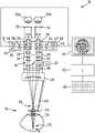
图1示出了第一眼部手术可视化系统以及患者眼睛;Figure 1 shows a first ocular surgery visualization system and a patient's eye;
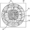
图2示出了用眼部手术可视化系统中的图像传感器捕捉的患者眼睛图像;Figure 2 shows an image of a patient's eye captured with an image sensor in an eye surgery visualization system;
图3示出了眼部手术可视化系统的计算机单元的图像处理例程的流程图;Figure 3 shows a flowchart of an image processing routine of a computer unit of the eye surgery visualization system;
图4示出了第二眼部手术可视化系统;并且Figure 4 shows a second eye surgery visualization system; and
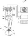
图5示出了第三眼部手术可视化系统。Figure 5 shows a third eye surgery visualization system.
具体实施方式Detailed ways
图1所示的第一眼部手术可视化系统10包含手术显微镜12,该手术显微镜用于立体地观察目标区域14。手术显微镜12包括具有显微镜主物镜系统18的成像光学单元16,所述成像光学单元被接纳在主体20中。在手术显微镜12中具有照明装置22,该照明装置方便于用穿过显微镜主物镜系统18的照明光束路径来照亮目标区域14。手术显微镜12具有无焦放大系统24,第一立体局部观察光束路径26和第二立体局部观察光束路径28被引导穿过该无焦放大系统。手术显微镜12具有连接至主体20的接口29上的双目镜筒30,所述双目镜筒具有用于观察者的左眼35a和右眼35b的第一目镜32和第二目镜34。第一立体局部观察光束路径26和第二立体局部观察光束路径28横穿手术显微镜12中的显微镜主物镜系统18。在手术显微镜12中具有第一图像捕捉装置36,该第一图像捕捉装置具有第一物镜系统38和第一图像传感器40。第一图像捕捉装置36用于捕捉来自第一立体局部观察光束路径26的图像信息。通过第二图像捕捉装置42,在手术显微镜12中可以捕捉来自第二立体局部观察光束路径28的图像信息。第二图像捕捉装置42具有第二物镜系统44并且包含第二图像传感器46。The first ocular
检眼镜检查附接模块48连接至手术显微镜12上,该检眼镜检查附接模块包括被接纳在检眼镜检查放大镜支撑件49中的检眼镜检查放大镜50。检眼镜检查放大镜50用于将位于患者眼睛54内部的部分52透过天然晶状体及其角膜成像到与第一图像传感器40上的成像平面58共轭并且与第二图像传感器46上的成像平面60共轭的中间图像平面56中。Connected to the operating
将检眼镜检查放大镜支撑件49涂成绿色,使得可以容易地将其与患者眼睛54的色调以及在眼科手术期间使用的手术器械的色调区分开、并且是在目标区域14中容易辨别的。应注意的是,特别是在本发明的替代性实施例中,还可以将检眼镜检查放大镜支撑件49涂成黄色。检眼镜检查放大镜支撑件49还可以具有任何使其能够在眼科手术期间在目标区域14中相对于具有体液(例如血液和身体组织以及手术器械)的图像背景容易地被看见的合适着色。The
眼部手术可视化系统10具有计算机单元62,该计算机单元包含图像处理例程,该图像处理例程用于目标区域14的图像,所述图像是通过第一图像传感器40和第二图像传感器46捕捉的。计算机单元62与作为图像显示装置的监视器64连接,该监视器用于将3-D图像信息可视化。眼部手术可视化系统10的计算机单元62可以通过作为输入界面的键盘66来控制。The eye
应注意的是,在眼部手术可视化系统的经修改的实施例中,还可以提供第一和第二监视器来将3-D图像信息可视化。于是,可以例如在第一监视器上显示目标区域的概览图像,并且可以在第二监视器上显示患者眼睛的放大图像。It should be noted that in modified embodiments of the eye surgery visualization system, first and second monitors may also be provided to visualize 3-D image information. Thus, for example, an overview image of the target area can be displayed on a first monitor, and a magnified image of the patient's eye can be displayed on a second monitor.
图2示出了患者眼睛在成像平面58中的图像68以及检眼镜检查放大镜50和手术器械59,所述图像是通过第一图像捕捉装置36捕捉的。图像68具有由穿过检眼镜检查放大镜50的成像光束路径产生的第一部分70,并且具有通过在从目标区域14出来时被引导经过检眼镜检查放大镜50的成像光束路径产生的、与第一部分互补的第二部分72。FIG. 2 shows an
计算机单元62中的图像处理例程的技术功能首先包括:将第一图像传感器40上的成像平面58中的目标区域14的图像68的第一部分与目标区域14的图像68的第二部分72分离,所述第一部分是通过图像传感器40上的第一图像捕捉装置36捕捉的并且是通过穿过检眼镜检查放大镜50的成像光束路径产生的,所述第二部分被成像在第一图像传感器40上并且是通过延伸到检眼镜检查放大镜50之外的成像光束路径产生的、并且与第一部分70互补。相应地,计算机单元62中的图像处理例程被设计用于将第二图像传感器46上的成像平面60中的同目标区域14的图像68相对应的图像的第一部分与同该目标区域14的图像68相对应的图像的第二部分72分离,即,分开,所述第一部分是通过第二图像捕捉装置42捕捉的并且是通过穿过检眼镜检查放大镜50的成像光束路径产生的,所述第二部分是通过第二图像传感器46捕捉的并且是通过延伸到检眼镜检查放大镜50之外的成像光束路径产生的、并且与第一部分70互补。The technical function of the image processing routine in the
此外,计算机单元62中的图像处理例程的功能在于对目标区域14的图像的第一部分70进行图像倒转操作,因为布置在患者眼睛54内部的部分52的图像(所述图像是在中间图像平面56中通过检眼镜检查放大镜50产生的)在中间图像平面56中是上下颠倒且前后颠倒的,即颠倒的。此外,计算机单元62中的图像处理例程的功能是组合目标区域14的图像的第一部分70与目标区域14的图像的第二部分72以形成合成的、横向上正确的且直立的目标图像,该图像接着可以显示在眼部手术可视化系统10的监视器64上。Furthermore, the function of the image processing routine in the
图3示出了图像处理例程的流程图74。计算机单元62中的图像处理例程具有图像部分分离阶段76,图像传感器40、46的图像被提供给该阶段。图像处理例程的图像部分分离阶段76包含用于识别检眼镜检查放大镜50的透镜边缘的算法,所述算法通过图像处理来识别在被提供给图像传感器40、46的图像中检眼镜检查放大镜支撑件49的结构。为此,在图像部分分离阶段76的算法中具有颜色评估功能,该功能与检眼镜检查放大镜支撑件49的特有颜色匹配。FIG. 3 shows a
该图像处理例程包含过滤阶段78。在过滤阶段78中,接着通过环形过滤器80对图像传感器40、46捕捉的图像的图像部分求卷积,其中在所捕捉的图像中改变过滤器中心81和过滤器半径r1和r2,以便接着由此在该图像中确定图像点集合,所述集合对应于检眼镜检查术放大镜支撑件49的环绕检眼镜检查放大镜50的那部分。接着确定环形过滤器80的过滤器内半径r1(在此,卷积函数取极值)为检眼镜检查放大镜50的一个边缘82。在以此方式确定的检眼镜检查放大镜50的边缘82的基础上,在随后的步骤中确立图2所示的目标区域14的图像的第一部分70的区域,以便接着在另外一步骤中将这些第一部分70与图2所示的目标区域14的图像的第二部分72的区域分离。The image processing routine includes a
接着将通过过滤阶段78与图像的第二部分72分离的目标区域14的图像的第一部分70提供给图像处理例程中的镜像阶段84。在镜像阶段84,将图像传感器40、46的图像的第一部分70通过关于位于图像68的图像平面中且彼此垂直的两条镜像轴线86、88的镜像经自同构转化成镜像第一部分70'。应理解的是,在替代性实施例中,镜像例程的自同构还可以被实施为第一部分70围绕与图像平面垂直的旋转轴线的旋转。此外,例如能够提供点镜像作为这种自同构。The
接着,镜像第一部分70'在图像处理例程中被传递至组合阶段90,在组合阶段中,将目标区域14的图像的镜像第一部分70'和第二部分72(所述图像是通过图像传感器40、46捕捉的)再次合成以形成目标区域合成图像68'。接着将合成图像的图像数据在监视器64上可视化为目标区域14的立体图像。Next, the mirrored first portion 70' is passed in an image processing routine to a combining
应注意的是,计算机单元62中的图像处理例程可以包含与通过第一图像传感器40或第二图像传感器46捕捉的图像数据相关的图像数据的评估阶段,所述评估阶段根据所捕捉的图像信息、例如呈患者眼睛54的视网膜的一部分的形式的图像信息,来抑制对第一或第二图像传感器40、46所提供的图像数据的处理。It should be noted that the image processing routines in the
应注意的是,例如,如果仅旨在将患者眼睛54的视网膜的图像作为目标区域图像来显示,则借助于图像处理例程可以避免对图像数据的不必要处理,该图像处理例程包含视网膜可视化例程,该视网膜可视化例程根据所捕捉的图像信息被触发,并且在该视网膜可视化例程中,将目标区域14的相应图像的第一部分70通过与第一部分关于位于该图像的图像平面内且彼此垂直的两条镜像轴线的镜像相对应的自同构转化成镜像第一部分、并且接着将其作为视网膜可视化例程目标区域图像输出至呈监视器64形式的图像显示装置。It should be noted that, for example, if only the image of the retina of the patient's
图4示出了第二眼部手术可视化系统10'。在眼部手术可视化系统10'中的组件和元件与上述眼部手术可视化系统10中的组件和元件相对应的程度上,这些组件和元件用相同的数字作为附图标记来表示。在眼部手术可视化系统10'中具有用于向内镜面反射数据92的装置,该装置连接至计算机单元62并且方便于第一和第二立体局部观察光束路径26、28中的覆盖在目标区域14的图像上的显示信息的显示,可在双目镜筒30中感知到该显示。Figure 4 shows a second ocular surgical visualization system 10'. To the extent that the components and elements in the ophthalmic surgical visualization system 10' correspond to those in the ophthalmic
图5示出了第三眼部手术可视化系统10”。在眼部手术可视化系统10”中的组件和元件与上述眼部手术可视化系统10中的组件和元件相对应的程度上,这些组件和元件用相同的数字作为附图标记来表示。不同于眼部手术可视化系统10和10'的手术显微镜12,眼部手术可视化系统10”的手术显微镜12是纯数字手术显微镜,用于通过第一图像传感器40和第二图像传感器46立体地捕捉目标区域14。Figure 5 illustrates a third ocular
就像第一眼部手术可视化系统10的计算机单元62,第二和第三眼部手术可视化系统10'、10”的计算机单元62包含用于处理目标区域的图像的图像处理例程,所述图像是通过图像传感器40、46捕捉的,该图像处理例程具有上文基于图3所描述的功能。Like the
总之,尤其应注意本发明的以下优选特征:眼部手术可视化系统10包括图像传感器40,46并且包括用于通过光学成像光束路径在图像传感器40、46上的成像平面58、60中产生目标区域14的图像68的成像系统。眼部手术可视化系统10包括:计算机单元62,该计算机单元包含用于目标区域14的图像68的图像处理例程,所述图像是通过图像传感器46捕捉的并且具有图像平面;以及用于使在计算机单元62中处理过的图像68的图像数据可视化的图像显示装置64。根据本发明,眼部手术可视化系统10、10'、10”具有检眼镜检查放大镜50,用于使位于患者眼睛54内的部分52成像在与图像传感器40、46上的成像平面58、60共轭的中间图像平面56中。该图像处理例程用于将图像传感器40、46上的成像平面60中的目标区域的图像68的第一部分70与目标区域14的图像68的第二部分72分离,所述第一部分是通过图像传感器40、46捕捉的并且是通过穿过检眼镜检查放大镜50的成像光束路径产生的,所述第二部分是通过图像传感器40、46捕捉的并且是通过延伸到检眼镜检查放大镜50之外的成像光束路径产生的、并且与第一部分互补,以便将目标区域14的图像68的第一部分70通过与第一部分70关于位于图像68的图像平面内且彼此垂直的两条镜像轴线86、88的镜像相对应的自同构转化成镜像第一部分70',并且以便组合镜像第一部分70'以及该图像68的与第一部分70互补的第二部分72以形成被提供给该图像显示装置的目标区域合成图像。In summary, particular attention should be paid to the following preferred features of the present invention: The eye
附图标记清单List of reference numbers
10,10',10” 眼部手术可视化系统10, 10', 10" Visualization System for Eye Surgery
12 手术显微镜12 Operating microscopes
14 目标区域14 target area
16 成像光学单元16 Imaging Optical Unit
18 显微镜主物镜系统18 Microscope Main Objective System
20 主体20 main body
22 照明装置22 Lighting device
24 无焦放大系统24 Afocal Magnification System
26 第一立体局部观察光束路径26 First Stereo Local Observation Beam Path
28 第二立体局部观察光束路径28 Second Stereo Partial Observation Beam Path
29 接口29 interface
30 双目镜筒30 Binocular Tube
32 第一目镜32 First eyepiece
34 第二目镜34 Second eyepiece
35a 左眼35a Left eye
35b 右眼35b right eye
36 第一图像捕捉装置36 First image capture device
38 第一物镜系统38 The first objective lens system
40 第一图像传感器40 First image sensor
42 第二图像捕捉装置42 Second Image Capture Device
44 第二物镜系统44 Second objective system
46 第二图像传感器46 Second image sensor
48 检眼镜检查附接模块48 Ophthalmoscope Attachment Module
49 检眼镜检查放大镜支撑件49 Ophthalmoscope Magnifier Support
50 检眼镜检查放大镜50 Ophthalmoscope Exam Magnifier
52 部分52 parts
54 患者眼睛54 Patient Eyes
56 中间图像平面56 Intermediate image plane
58 成像平面58 Imaging planes
59 手术器械59 Surgical instruments
60 成像平面60 Imaging planes
62 计算机单元62 computer unit
64 图像显示装置(监视器)64 Image display device (monitor)
66 键盘66 keyboard
68 图像68 images
68' 目标区域合成图像68' target area composite image
70 第一部分70 Part 1
70' 镜像第一部分70' Mirror Part 1
72 第二部分72 Part II
74 流程图74 Flowchart
76 图像部分分离阶段76 Image part separation stage
78 过滤阶段78 Filter stage
80 环形过滤器80 Ring Filter
81 过滤器中心81 Filter Center
82 边缘82 Edge
84 镜像阶段84 Mirror Phase
86,88 镜像轴线86, 88 Mirror axis
90 组合阶段90 Combination Stages
92 向内镜面反射数据92 Inward Specular Data
r1,r2 过滤器半径r1, r2 filter radius
Claims (11)
Priority Applications (1)
| Application Number | Priority Date | Filing Date | Title |
|---|---|---|---|
| CN202210417344.7ACN114848287A (en) | 2017-09-12 | 2018-09-11 | Visual system for eye operation |
Applications Claiming Priority (2)
| Application Number | Priority Date | Filing Date | Title |
|---|---|---|---|
| DE102017121085.7 | 2017-09-12 | ||
| DE102017121085.7ADE102017121085C5 (en) | 2017-09-12 | 2017-09-12 | eye surgery visualization system |
Related Child Applications (1)
| Application Number | Title | Priority Date | Filing Date |
|---|---|---|---|
| CN202210417344.7ADivisionCN114848287A (en) | 2017-09-12 | 2018-09-11 | Visual system for eye operation |
Publications (2)
| Publication Number | Publication Date |
|---|---|
| CN109481138A CN109481138A (en) | 2019-03-19 |
| CN109481138Btrue CN109481138B (en) | 2022-04-19 |
Family
ID=65004056
Family Applications (2)
| Application Number | Title | Priority Date | Filing Date |
|---|---|---|---|
| CN201811055640.7AActiveCN109481138B (en) | 2017-09-12 | 2018-09-11 | Eye Surgery Visualization System |
| CN202210417344.7APendingCN114848287A (en) | 2017-09-12 | 2018-09-11 | Visual system for eye operation |
Family Applications After (1)
| Application Number | Title | Priority Date | Filing Date |
|---|---|---|---|
| CN202210417344.7APendingCN114848287A (en) | 2017-09-12 | 2018-09-11 | Visual system for eye operation |
Country Status (4)
| Country | Link |
|---|---|
| US (1) | US10750944B2 (en) |
| JP (2) | JP7224816B2 (en) |
| CN (2) | CN109481138B (en) |
| DE (1) | DE102017121085C5 (en) |
Families Citing this family (8)
| Publication number | Priority date | Publication date | Assignee | Title |
|---|---|---|---|---|
| JP7150867B2 (en) | 2018-09-28 | 2022-10-11 | 株式会社エビデント | microscope system |
| EP4345776A3 (en) | 2018-09-28 | 2024-06-19 | Evident Corporation | Microscope system, projection unit, and image projection method |
| JP7150866B2 (en)* | 2018-09-28 | 2022-10-11 | 株式会社エビデント | Microscope system, projection unit, and image projection method |
| WO2020066042A1 (en) | 2018-09-28 | 2020-04-02 | オリンパス株式会社 | Microscope system, projection unit, and image projection method |
| JP2020130607A (en) | 2019-02-20 | 2020-08-31 | ソニー株式会社 | Control device, ophthalmic microscope system, ophthalmic microscope and image processing device |
| US20230027801A1 (en)* | 2020-01-06 | 2023-01-26 | The Johns Hopkins University | Overlaying augmented reality (ar) content within an ar headset coupled to a magnifying loupe |
| DE102020104486A1 (en) | 2020-02-20 | 2021-08-26 | Möller-Wedel GmbH & Co. KG | Method and device for stereoscopic imaging |
| CN118251168A (en)* | 2021-11-09 | 2024-06-25 | 爱尔康公司 | Stereoscopic imaging apparatus with multiple fixed magnifications |
Citations (13)
| Publication number | Priority date | Publication date | Assignee | Title |
|---|---|---|---|---|
| DE4114646C2 (en)* | 1991-05-04 | 1996-02-29 | Zeiss Carl Fa | Ophthalmoscope attachment for a surgical microscope |
| CN102159128A (en)* | 2008-07-24 | 2011-08-17 | 卡尔蔡司外科器械有限责任公司 | Eye surgery system and method for preparation and carrying out eye surgery |
| WO2013037606A1 (en)* | 2011-09-16 | 2013-03-21 | Carl Zeiss Meditec Ag | Determination of the azimuthal orientation of a patient's eye |
| CN103153386A (en)* | 2010-09-01 | 2013-06-12 | 爱尔康研究有限公司 | Method and system for posterior segment volume measurement |
| EP2965688A1 (en)* | 2014-07-10 | 2016-01-13 | Carl Zeiss Meditec AG | Eye surgery system |
| CN105283901A (en)* | 2013-03-15 | 2016-01-27 | 光学实验室成像公司 | Calibration and image processing device, method and system |
| CN105748033A (en)* | 2012-12-28 | 2016-07-13 | 佳能株式会社 | Image Processing Apparatus And Image Processing Method |
| CN106053349A (en)* | 2015-04-12 | 2016-10-26 | 台医光电科技股份有限公司 | Optical detection module, optical detection device and optical detection method |
| WO2017063714A1 (en)* | 2015-10-16 | 2017-04-20 | Novartis Ag | Ophthalmic surgical mage processing |
| CN106667658A (en)* | 2011-10-10 | 2017-05-17 | 视乐有限公司 | Laser system for eye surgical operation and interface device |
| JP2017113134A (en)* | 2015-12-22 | 2017-06-29 | 株式会社トプコン | Microscope system for ophthalmology |
| CN107106011A (en)* | 2014-12-29 | 2017-08-29 | 诺华股份有限公司 | OCT surgical operation visualization systems with macula lutea contact lens |
| WO2017149181A1 (en)* | 2016-02-29 | 2017-09-08 | Universidad De Murcia | Instrument for obtaining images of the eye and associated method |
Family Cites Families (17)
| Publication number | Priority date | Publication date | Assignee | Title |
|---|---|---|---|---|
| DE3539009A1 (en) | 1985-11-02 | 1987-05-07 | Moeller J D Optik | Attachment for a stereoscopic surgical microscope for ophthalmic surgery |
| BE1003017A4 (en) | 1990-03-29 | 1991-10-22 | K U Leuven Res & Dev Vzw | Apparatus for observing the eye comprising means for reversing the image. |
| CA2128606C (en) | 1992-01-21 | 2008-07-22 | Philip S. Green | Teleoperator system and method with telepresence |
| DE29905969U1 (en) | 1999-04-08 | 1999-07-08 | Oculus Optikgeräte GmbH, 35582 Wetzlar | Stereoscopic microscope |
| WO2001089373A2 (en)* | 2000-05-20 | 2001-11-29 | Sensomotoric Instruments Gmbh | Method and apparatus for measuring ocular alignment |
| JP3979877B2 (en) | 2002-05-17 | 2007-09-19 | 興和株式会社 | Ophthalmic examination equipment |
| DE102005040473B4 (en)* | 2005-08-26 | 2007-05-24 | Leica Microsystems (Schweiz) Ag | stereomicroscope |
| US10398599B2 (en)* | 2007-10-05 | 2019-09-03 | Topcon Medical Laser Systems Inc. | Semi-automated ophthalmic photocoagulation method and apparatus |
| DE102008011836A1 (en)* | 2008-02-28 | 2009-09-03 | Carl Zeiss Meditec Ag | Ophthalmological device and method for observation, examination, diagnosis and / or therapy of an eye |
| JP2010000110A (en) | 2008-06-18 | 2010-01-07 | Topcon Corp | Binocular stereo video microscope apparatus |
| DE102009030504B4 (en) | 2009-06-24 | 2024-06-06 | Carl Zeiss Meditec Ag | Eye surgery microscopy system |
| DE102012012281A1 (en)* | 2012-06-21 | 2013-12-24 | Carl Zeiss Meditec Ag | EYE SURGERY MICROSCOPE WITH AMETROPIC MEASUREMENT DEVICE |
| JP6202924B2 (en)* | 2013-07-31 | 2017-09-27 | キヤノン株式会社 | Imaging apparatus and imaging method |
| JP6527668B2 (en)* | 2014-05-02 | 2019-06-05 | 株式会社トプコン | Ophthalmic surgery apparatus and attachment for ophthalmic surgery |
| US9645379B2 (en) | 2014-12-29 | 2017-05-09 | Novartis Ag | Magnification in ophthalmic procedures and associated devices, systems, and methods |
| JP6502720B2 (en) | 2015-03-27 | 2019-04-17 | 株式会社トプコン | Ophthalmic microscope |
| JP7258873B2 (en)* | 2017-10-27 | 2023-04-17 | アルコン インコーポレイティド | OCT Image Display with Foot Pedal Control for Vitreoretinal Surgery |
- 2017
- 2017-09-12DEDE102017121085.7Apatent/DE102017121085C5/enactiveActive
- 2018
- 2018-09-06JPJP2018166633Apatent/JP7224816B2/enactiveActive
- 2018-09-11CNCN201811055640.7Apatent/CN109481138B/enactiveActive
- 2018-09-11CNCN202210417344.7Apatent/CN114848287A/enactivePending
- 2018-09-12USUS16/129,610patent/US10750944B2/enactiveActive
- 2023
- 2023-02-08JPJP2023017437Apatent/JP7507269B2/enactiveActive
Patent Citations (13)
| Publication number | Priority date | Publication date | Assignee | Title |
|---|---|---|---|---|
| DE4114646C2 (en)* | 1991-05-04 | 1996-02-29 | Zeiss Carl Fa | Ophthalmoscope attachment for a surgical microscope |
| CN102159128A (en)* | 2008-07-24 | 2011-08-17 | 卡尔蔡司外科器械有限责任公司 | Eye surgery system and method for preparation and carrying out eye surgery |
| CN103153386A (en)* | 2010-09-01 | 2013-06-12 | 爱尔康研究有限公司 | Method and system for posterior segment volume measurement |
| WO2013037606A1 (en)* | 2011-09-16 | 2013-03-21 | Carl Zeiss Meditec Ag | Determination of the azimuthal orientation of a patient's eye |
| CN106667658A (en)* | 2011-10-10 | 2017-05-17 | 视乐有限公司 | Laser system for eye surgical operation and interface device |
| CN105748033A (en)* | 2012-12-28 | 2016-07-13 | 佳能株式会社 | Image Processing Apparatus And Image Processing Method |
| CN105283901A (en)* | 2013-03-15 | 2016-01-27 | 光学实验室成像公司 | Calibration and image processing device, method and system |
| EP2965688A1 (en)* | 2014-07-10 | 2016-01-13 | Carl Zeiss Meditec AG | Eye surgery system |
| CN107106011A (en)* | 2014-12-29 | 2017-08-29 | 诺华股份有限公司 | OCT surgical operation visualization systems with macula lutea contact lens |
| CN106053349A (en)* | 2015-04-12 | 2016-10-26 | 台医光电科技股份有限公司 | Optical detection module, optical detection device and optical detection method |
| WO2017063714A1 (en)* | 2015-10-16 | 2017-04-20 | Novartis Ag | Ophthalmic surgical mage processing |
| JP2017113134A (en)* | 2015-12-22 | 2017-06-29 | 株式会社トプコン | Microscope system for ophthalmology |
| WO2017149181A1 (en)* | 2016-02-29 | 2017-09-08 | Universidad De Murcia | Instrument for obtaining images of the eye and associated method |
Non-Patent Citations (2)
| Title |
|---|
| Reaction times and the decision-making process in endoscopic surgery - An experimental study;B.Zheng;<Surgical Endoscopy>;20030619;第1475-1480页* |
| Stevens-Johnson综合征眼部并发症手术患者的护理;刘艳英;《中国实用医药》;20170820;第148-150页* |
Also Published As
| Publication number | Publication date |
|---|---|
| DE102017121085C5 (en) | 2025-01-23 |
| JP7507269B2 (en) | 2024-06-27 |
| JP2019051304A (en) | 2019-04-04 |
| CN114848287A (en) | 2022-08-05 |
| DE102017121085B3 (en) | 2019-01-31 |
| JP2023053017A (en) | 2023-04-12 |
| JP7224816B2 (en) | 2023-02-20 |
| CN109481138A (en) | 2019-03-19 |
| US10750944B2 (en) | 2020-08-25 |
| US20190076020A1 (en) | 2019-03-14 |
Similar Documents
| Publication | Publication Date | Title |
|---|---|---|
| CN109481138B (en) | Eye Surgery Visualization System | |
| EP3241051B1 (en) | Magnification in ophthalmic procedures and associated devices, systems, and methods | |
| US10989911B2 (en) | Method for operating a medical-optical display system | |
| CN108627962B (en) | The microscopical method of surgical operation microscope and operation with imaging sensor and display | |
| US10151909B2 (en) | Surgical microscope and method for highlighting eye lens pieces | |
| TWI813631B (en) | Ophthalmic optical system, ophthalmic apparatus and ophthalmic system | |
| JP7571835B2 (en) | Ophthalmic Equipment | |
| WO2022085540A1 (en) | Ophthalmological observation device, ophthalmological image processing device, ophthalmological image processing method, program, and recording medium | |
| EP4328648A1 (en) | Digital microscope for medical procedure | |
| US20250082202A1 (en) | Endoscope Having a Dual Camera Module | |
| CN111317439A (en) | Reality augmentation microscope and reality augmentation method thereof |
Legal Events
| Date | Code | Title | Description |
|---|---|---|---|
| PB01 | Publication | ||
| PB01 | Publication | ||
| SE01 | Entry into force of request for substantive examination | ||
| SE01 | Entry into force of request for substantive examination | ||
| GR01 | Patent grant | ||
| GR01 | Patent grant |