CN109470173B - Double-channel simultaneous phase shift interference microscope system - Google Patents
Double-channel simultaneous phase shift interference microscope systemDownload PDFInfo
- Publication number
- CN109470173B CN109470173BCN201811635318.1ACN201811635318ACN109470173BCN 109470173 BCN109470173 BCN 109470173BCN 201811635318 ACN201811635318 ACN 201811635318ACN 109470173 BCN109470173 BCN 109470173B
- Authority
- CN
- China
- Prior art keywords
- light
- unit
- phase
- wave plate
- measurement
- Prior art date
- Legal status (The legal status is an assumption and is not a legal conclusion. Google has not performed a legal analysis and makes no representation as to the accuracy of the status listed.)
- Active
Links
Images


Classifications
- G—PHYSICS
- G01—MEASURING; TESTING
- G01B—MEASURING LENGTH, THICKNESS OR SIMILAR LINEAR DIMENSIONS; MEASURING ANGLES; MEASURING AREAS; MEASURING IRREGULARITIES OF SURFACES OR CONTOURS
- G01B11/00—Measuring arrangements characterised by the use of optical techniques
- G01B11/24—Measuring arrangements characterised by the use of optical techniques for measuring contours or curvatures
- G01B11/2441—Measuring arrangements characterised by the use of optical techniques for measuring contours or curvatures using interferometry
- G—PHYSICS
- G01—MEASURING; TESTING
- G01B—MEASURING LENGTH, THICKNESS OR SIMILAR LINEAR DIMENSIONS; MEASURING ANGLES; MEASURING AREAS; MEASURING IRREGULARITIES OF SURFACES OR CONTOURS
- G01B11/00—Measuring arrangements characterised by the use of optical techniques
- G01B11/24—Measuring arrangements characterised by the use of optical techniques for measuring contours or curvatures
- G01B11/25—Measuring arrangements characterised by the use of optical techniques for measuring contours or curvatures by projecting a pattern, e.g. one or more lines, moiré fringes on the object
- G01B11/254—Projection of a pattern, viewing through a pattern, e.g. moiré
- G—PHYSICS
- G01—MEASURING; TESTING
- G01B—MEASURING LENGTH, THICKNESS OR SIMILAR LINEAR DIMENSIONS; MEASURING ANGLES; MEASURING AREAS; MEASURING IRREGULARITIES OF SURFACES OR CONTOURS
- G01B9/00—Measuring instruments characterised by the use of optical techniques
- G01B9/02—Interferometers
- G01B9/02001—Interferometers characterised by controlling or generating intrinsic radiation properties
Landscapes
- Physics & Mathematics (AREA)
- General Physics & Mathematics (AREA)
- Engineering & Computer Science (AREA)
- Computer Vision & Pattern Recognition (AREA)
- Instruments For Measurement Of Length By Optical Means (AREA)
- Investigating Or Analysing Materials By Optical Means (AREA)
Abstract
Translated fromChinese
Description
Translated fromChinese技术领域technical field
本发明涉及一种光学干涉显微系统,尤其涉及一种双通道同时相移干涉显微系统。The invention relates to an optical interference microscope system, in particular to a dual-channel simultaneous phase shift interference microscope system.
背景技术Background technique
近几十年来,随着光电图像传感技术、计算机技术、图像处理技术的发展,光学相位测量显微术也取得了很大的进步;光学相位测量显微术具有全场、快速、高精度、非接触、无损伤的优点,通过光电图像传感器(如CCD、CMOS)采集一幅干涉图或多幅相移量单调变化的干涉图,利用相位解调算法即可计算出样品的相位分布,同时实现样品三维形貌信息的高精度测量,测量精度可达到1/100波长;在细胞生物学、生物组织、器官、临床检测与诊断、光学表面检测等方面有着广泛的应用。In recent decades, with the development of photoelectric image sensing technology, computer technology, and image processing technology, optical phase measurement microscopy has also made great progress; , non-contact, non-destructive advantages, through the photoelectric image sensor (such as CCD, CMOS) to collect an interferogram or multiple interferograms with monotonically varying phase shifts, and use the phase demodulation algorithm to calculate the phase distribution of the sample, At the same time, it can achieve high-precision measurement of the three-dimensional topography information of the sample, and the measurement accuracy can reach 1/100 wavelength; it has a wide range of applications in cell biology, biological tissue, organs, clinical detection and diagnosis, and optical surface detection.
相移干涉测量技术与其他干涉测量技术相比有着背景噪声消除比较彻底、测量精度高等优点,但是也存在需要在不同时刻利用相移装置采集多幅相移干涉图的问题,使得测量结果易受到外界振动和空气串扰的影响,并且无法实现动态相位测量。而采用空域同时相移技术可以解决上述的问题,它是利用偏振光学元件对正交偏振光进行相移,在一个或多个相机的感光芯片的靶面上同时形成三幅或四幅相移量相差pi/2的干涉图,再通过三步或四步相移算法计算出相位的方法。主要有三种方式可实现:一是利用分光棱镜和偏振器件,在多个相机的感光芯片的靶面上形成具有不同相移量的干涉图;二是利用光栅或者其他的分光元件和偏振器件,使得在一个感光芯片的靶面上的不同区域,同时采集到具有不同相移量的干涉图;三是利用偏振相移阵列器件,使得在一个相机的感光芯片的靶面上,以四个像素为一个单元,不同位置的像素具有特定的相移期间,采集到的图像可通过分离和插值的方式形成相移干涉图,再通过相移相位恢复算法即可求的相位分布,实现动态相位测量。Compared with other interferometric techniques, phase-shift interferometry technology has the advantages of more thorough background noise elimination and higher measurement accuracy, but there is also the problem that multiple phase-shift interferograms need to be collected at different times by using a phase-shift device, which makes the measurement results vulnerable. The influence of external vibration and air crosstalk, and dynamic phase measurement cannot be achieved. The spatial domain simultaneous phase shift technology can solve the above problems. It uses polarized optical elements to phase shift the orthogonally polarized light, and simultaneously forms three or four phase shifts on the target surface of the photosensitive chip of one or more cameras. The interferogram with a difference of pi/2, and then calculate the phase through a three-step or four-step phase shift algorithm. There are three main ways to achieve it: one is to use beam splitting prisms and polarizing devices to form interference patterns with different phase shifts on the target surfaces of the photosensitive chips of multiple cameras; the other is to use gratings or other beam splitting elements and polarizing devices, The interferograms with different phase shifts are simultaneously collected in different areas on the target surface of a photosensitive chip; the third is to use polarization phase shift array devices to make four pixels on the target surface of the photosensitive chip of a camera. It is a unit, the pixels at different positions have a specific phase shift period, the collected images can be separated and interpolated to form a phase shift interferogram, and then the phase distribution can be obtained through the phase shift phase recovery algorithm to realize dynamic phase measurement. .
以上方法都可实现空域的同时相移的动态相位测量,但是也存在以下一些问题:All of the above methods can realize the dynamic phase measurement of simultaneous phase shift in the spatial domain, but there are also some problems as follows:
一、多个图像传感器系统需要保证多相机同步采集图像,而多个CCD的光电性能不一致、空间相对位置不同都会对测量结果带来较大影响;1. Multiple image sensor systems need to ensure that multiple cameras collect images synchronously, and the photoelectric performance of multiple CCDs is inconsistent and the spatial relative positions are different, which will have a greater impact on the measurement results;
二、单个CCD靶面不同区域同时采集到多幅相移干涉图则会受到诸多条件的限制,如光栅衍射方向受波长的影响,使得该方法只能应用于单波长测量而不能进行白光或窄带光的测量,空间分辨率不足、需要特殊图像传感器等;2. The simultaneous acquisition of multiple phase-shifted interferograms from different areas of a single CCD target surface is limited by many conditions, such as the diffraction direction of the grating is affected by the wavelength, so this method can only be applied to single-wavelength measurement and cannot be used for white light or narrow band. Light measurement, insufficient spatial resolution, need special image sensor, etc.;
三、像素掩膜元件则因制作成本昂贵,很难实现广泛的商业应用。Third, the pixel mask element is difficult to achieve a wide range of commercial applications due to the high production cost.
发明内容SUMMARY OF THE INVENTION
本发明针对背景技术中的问题提供一种双通道同时相移干涉显微系统,降低成本、技术难度,在具备空域同时相移功能的基础上,还具备时域相移功能,能够实现时域相移相位测量,也能够对测量系统进行校正。In view of the problems in the background technology, the present invention provides a dual-channel simultaneous phase-shift interference microscope system, which reduces cost and technical difficulty, and has a time-domain phase-shift function on the basis of the space-domain simultaneous phase-shift function, which can realize the time-domain phase shift function. Phase-shift phase measurements, which also enable calibration of the measurement system.
为了实现上述目的,本发明提出一种双通道同时相移干涉显微系统,至少包括:分光单元、参考光路单元、测量光路单元、合束单元及图像采集单元;其中,In order to achieve the above purpose, the present invention proposes a dual-channel simultaneous phase-shift interference microscope system, which at least includes: a light splitting unit, a reference light path unit, a measurement light path unit, a beam combining unit and an image acquisition unit; wherein,
所述分光单元,用于将入射的光波分离为传输方向相互垂直、偏振面相互正交的测量光束及参考光束;The spectroscopic unit is used to separate the incident light wave into a measurement beam and a reference beam whose transmission directions are perpendicular to each other and whose polarization planes are perpendicular to each other;
所述参考光路单元,用于传输参考光束及将参考光束进行空域相移;The reference optical path unit is used for transmitting the reference beam and performing a spatial phase shift on the reference beam;
所述测量光路单元,用于传输测量光束及对测量光束进行空域相移,并将测量光束经过待测量物体后生成物光束;The measuring optical path unit is used for transmitting the measuring beam and performing spatial phase shift on the measuring beam, and generating the object beam after passing the measuring beam through the object to be measured;
所述合束单元,用于对空域相移后的参考光束和物光束进行合束;The beam combining unit is used to combine the reference beam and the object beam after the spatial phase shift;
所述图像采集单元,用于对合束后的光束进行分光并在两个通道上采集获得两幅相移干涉条纹图。The image acquisition unit is used for splitting the combined beam and acquiring two phase-shift interference fringe patterns on two channels.
优选地,该系统还包括:光源单元,用于生成光强分布均匀的平面光波,并将平面光波传输至分光单元。Preferably, the system further includes: a light source unit for generating a plane light wave with uniform light intensity distribution, and transmitting the plane light wave to the light splitting unit.
优选地,所述的光源单元,包括:光源发生器、偏振衰减器和光束扩束准直组件,其中,所述光源发生器产生线偏振光波,线偏振光波经过偏振衰减器进行衰减及旋转光波偏振方向,在经过扩束准直组件形成光强分布均匀的平面光波。Preferably, the light source unit includes: a light source generator, a polarization attenuator and a beam expansion and collimation assembly, wherein the light source generator generates a linearly polarized light wave, and the linearly polarized light wave passes through the polarization attenuator to attenuate and rotate the light wave The polarization direction forms a plane light wave with uniform light intensity distribution after passing through the beam expanding and collimating components.
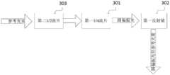
优选地,所述的参考光路单元,可依次设置为:第一1/4波片和第一反射镜,参考光束经过所述第一1/4波片及第一反射镜反射后形成圆偏振光的参考光束;Preferably, the reference optical path unit can be sequentially set as: a first 1/4 wave plate and a first reflection mirror, and the reference beam is reflected by the first 1/4 wave plate and the first reflection mirror to form circular polarization the reference beam of light;
所述的测量光路单元,设置为:第一1/2波片、第二反射镜和一个成像物镜,待测量物体设置于成像物镜前端,测量光束经过第一1/2波片形成与水平方向存在一定夹角的线偏振光,线偏振光经第二反射镜照射到待测量物体表面,透射过待测量物体后经成像物镜形成物光波。The measuring optical path unit is set as: a first 1/2 wave plate, a second reflecting mirror and an imaging objective lens, the object to be measured is set at the front end of the imaging objective lens, and the measurement beam is formed by the first 1/2 wave plate and is aligned in the horizontal direction. There is a certain angle of linearly polarized light, the linearly polarized light is irradiated to the surface of the object to be measured through the second mirror, and the object light wave is formed by the imaging objective lens after transmitting through the object to be measured.
优选地,所述的参考光路单元,还可依次设置为:第二1/2波片、第一1/4波片和第一反射镜,参考光束经过所述第二1/2波片、第一1/4波片及第一反射镜反射后形成圆偏振光的参考光束;Preferably, the reference optical path unit can also be set as follows: a second 1/2 wave plate, a first 1/4 wave plate and a first reflection mirror, and the reference beam passes through the second 1/2 wave plate, The reference beam of circularly polarized light is formed after the first 1/4 wave plate and the first reflecting mirror are reflected;
所述的测量光路单元,设置为:第一1/2波片、第二反射镜和一个成像物镜,待测量物体设置于成像物镜前端,测量光束经过第一1/2波片形成与水平方向存在一定夹角的线偏振光,线偏振光经第二反射镜照射到待测量物体表面,透射过待测量物体后经成像物镜形成物光波。The measuring optical path unit is set as: a first 1/2 wave plate, a second reflecting mirror and an imaging objective lens, the object to be measured is set at the front end of the imaging objective lens, and the measurement beam is formed by the first 1/2 wave plate and is aligned in the horizontal direction. There is a certain angle of linearly polarized light, the linearly polarized light is irradiated to the surface of the object to be measured through the second mirror, and the object light wave is formed by the imaging objective lens after transmitting through the object to be measured.
优选地,所述的参考光路单元,还可依次设置为:第一1/4波片、第二1/2波片和第一反射镜,参考光束经过所述第一1/4波片、第二1/2波片及第一反射镜反射后形成圆偏振光的参考光束;Preferably, the reference optical path unit can also be set as follows: a first 1/4 wave plate, a second 1/2 wave plate and a first reflection mirror, and the reference beam passes through the first 1/4 wave plate, A reference beam of circularly polarized light is formed after the second 1/2 wave plate and the first reflecting mirror are reflected;
所述的测量光路单元,设置为:第一1/2波片、第二反射镜和一个成像物镜,待测量物体设置于成像物镜前端,测量光束经过第一1/2波片形成与水平方向存在一定夹角的线偏振光,线偏振光经第二反射镜照射到待测量物体表面,透射过待测量物体后经成像物镜形成物光波。The measuring optical path unit is set as: a first 1/2 wave plate, a second reflecting mirror and an imaging objective lens, the object to be measured is set at the front end of the imaging objective lens, and the measurement beam is formed by the first 1/2 wave plate and is aligned in the horizontal direction. There is a certain angle of linearly polarized light, the linearly polarized light is irradiated to the surface of the object to be measured through the second mirror, and the object light wave is formed by the imaging objective lens after transmitting through the object to be measured.
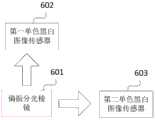
优选地,所述的图像采集单元,包括:一个偏振分光棱镜、第一光电图像传感器和第二光电图像传感器,合束后的光束经过偏振分光棱镜进行分光获得相互垂直的两路光束,通过第一光电图像传感器和第二光电图像传感器两个通道上采集获得两幅相移干涉条纹图。Preferably, the image acquisition unit includes: a polarizing beam splitter prism, a first photoelectric image sensor and a second photoelectric image sensor, the combined beam is split by the polarizing beam splitter prism to obtain two mutually perpendicular beams, Two phase-shifted interference fringe patterns are obtained by collecting on two channels of a photoelectric image sensor and a second photoelectric image sensor.
优选地,所述的反射镜可替换为压电陶瓷,以对参考光束进行时域相移。Preferably, the reflecting mirror can be replaced with piezoelectric ceramics to perform time-domain phase shift on the reference beam.
优选地,所述的一定夹角为45°。Preferably, the certain included angle is 45°.
优选地,所述的合束后的光束经过偏振分光棱镜进行分光获得相互垂直的两路光束后,使光束尺寸与第一光电图像传感器和第一光电图像传感器的光敏面尺寸相匹配。Preferably, after the combined beam is split by a polarization beam splitting prism to obtain two mutually perpendicular beams, the beam size is matched with the size of the first photoelectric image sensor and the photosensitive surface of the first photoelectric image sensor.
本发明提出一种双通道同时相移干涉显微系统,具有如下有益效果:The present invention proposes a dual-channel simultaneous phase-shift interference microscope system, which has the following beneficial effects:
(1)本发明专利为时空混合相移双通道干涉显微系统,结合两步相移算法,可以实现静态和动态相位测量,相对其他空域相移技术,大大降低了成本和技术难度;(1) The patent of the present invention is a space-time hybrid phase-shifting dual-channel interference microscope system. Combined with a two-step phase-shift algorithm, it can realize static and dynamic phase measurement, which greatly reduces the cost and technical difficulty compared with other spatial-domain phase-shift technologies;
(2)本发明专利所述干涉显微系统在具备空域同时相移功能的基础上,还具备时域相移功能,能够实现时域相移相位测量(在参考光路将反射镜换成PZT),也能够对测量系统进行校正;(2) On the basis of the simultaneous phase shift function in the space domain, the interference microscope system described in the patent of the present invention also has the function of phase shift in the time domain, which can realize the phase shift measurement in the time domain (replace the mirror with PZT in the reference optical path) , and can also calibrate the measurement system;
(3)本发明专利相较于其他系统更为简单,对于两CCD空间位置的匹配操作难度更低,而且系统光能利用率更高。(3) Compared with other systems, the patent of the present invention is simpler, the matching operation of the spatial positions of the two CCDs is less difficult, and the utilization rate of light energy of the system is higher.
附图说明Description of drawings
为了更清楚地说明本发明实施例或现有技术中的技术方案,下面将对实施例或现有技术描述中所需要使用的附图作简单地介绍,显而易见地,下面描述中的附图仅仅是本发明的一些实施例,对于本领域普通技术人员来讲,在不付出创造性劳动的前提下,还可以根据这些附图示出的结构获得其他的附图。In order to illustrate the embodiments of the present invention or the technical solutions in the prior art more clearly, the following briefly introduces the accompanying drawings that need to be used in the description of the embodiments or the prior art. Obviously, the drawings in the following description are only These are some embodiments of the present invention. For those of ordinary skill in the art, other drawings can also be obtained according to the structures shown in these drawings without creative efforts.
图1为本发明第一优选实施例中双通道同时相移干涉显微系统结构框图;1 is a structural block diagram of a dual-channel simultaneous phase-shift interference microscope system in a first preferred embodiment of the present invention;
图2为本发明第一优选实施例中光源单元结构框图;FIG. 2 is a structural block diagram of a light source unit in the first preferred embodiment of the present invention;
图3为本发明第一优选实施例中参考光路单元结构框图;3 is a structural block diagram of a reference optical path unit in the first preferred embodiment of the present invention;
图4为本发明第一优选实施例中测量光路单元结构框图;FIG. 4 is a structural block diagram of the measurement optical path unit in the first preferred embodiment of the present invention;
图5为本发明第一优选实施例中图像采集单元结构框图;5 is a structural block diagram of an image acquisition unit in the first preferred embodiment of the present invention;
图6为本发明第一优选实施例中双通道同时相移干涉显微系统整体细节结构框图;6 is a block diagram of the overall detailed structure of the dual-channel simultaneous phase-shift interference microscopy system in the first preferred embodiment of the present invention;
图7为本发明第二优选实施例中参考光路单元结构框图;7 is a structural block diagram of a reference optical path unit in a second preferred embodiment of the present invention;
图8为本发明第三优选实施例中参考光路单元结构框图;8 is a structural block diagram of a reference optical path unit in a third preferred embodiment of the present invention;
符号说明:Symbol Description:
1-光源单元;2-分光单元;3-参考光路单元;4-测量光路单元;5-合束单元;6-图像采集单元;101-光源发生器;102-偏振衰减器;103-光束扩束准直组件;301-第一1/4波片;302-第一反射镜;303-第二1/2波片;401-第一1/2波片;402-第二反射镜;403-成像物镜;601-偏振分光棱镜;602-第一单色黑白图像传感器;603-第二单色黑白图像传感器;1-light source unit; 2-beam splitting unit; 3-reference light path unit; 4-measurement light path unit; 5-beam combining unit; 6-image acquisition unit; 101-light source generator; 102-polarization attenuator; 103-beam expander Beam collimation assembly; 301-first 1/4 waveplate; 302-first mirror; 303-second 1/2 waveplate; 401-first 1/2 waveplate; 402-second mirror; 403 - Imaging objective lens; 601 - polarizing beam splitter prism; 602 - first monochrome black and white image sensor; 603 - second monochrome black and white image sensor;
本发明目的的实现、功能特点及优点将结合实施例,参照附图做进一步说明。The realization, functional characteristics and advantages of the present invention will be further described with reference to the accompanying drawings in conjunction with the embodiments.
具体实施方式Detailed ways
下面将结合本发明实施例中的附图,对本发明实施例中的技术方案进行清楚、完整地描述,显然,所描述的实施例仅仅是本发明的一部分实施例,而不是全部的实施例。基于本发明中的实施例,本领域普通技术人员在没有作出创造性劳动前提下所获得的所有其他实施例,都属于本发明保护的范围。The technical solutions in the embodiments of the present invention will be clearly and completely described below with reference to the accompanying drawings in the embodiments of the present invention. Obviously, the described embodiments are only a part of the embodiments of the present invention, not all of the embodiments. Based on the embodiments of the present invention, all other embodiments obtained by those of ordinary skill in the art without creative efforts shall fall within the protection scope of the present invention.
需要说明,若本发明实施例中有涉及方向性指示(诸如上、下、左、右、前、后……),则该方向性指示仅用于解释在某一特定姿态(如附图所示)下各部件之间的相对位置关系、运动情况等,如果该特定姿态发生改变时,则该方向性指示也相应地随之改变。It should be noted that if there are directional indications (such as up, down, left, right, front, back, etc.) involved in the embodiments of the present invention, the directional indications are only used to explain a certain posture (as shown in the accompanying drawings). If the specific posture changes, the directional indication also changes accordingly.
另外,若本发明实施例中有涉及“第一”、“第二”等的描述,则该“第一”、“第二”等的描述仅用于描述目的,而不能理解为指示或暗示其相对重要性或者隐含指明所指示的技术特征的数量。由此,限定有“第一”、“第二”的特征可以明示或者隐含地包括至少一个该特征。另外,各个实施例之间的技术方案可以相互结合,但是必须是以本领域普通技术人员能够实现为基础,当技术方案的结合出现相互矛盾或无法实现时应当认为这种技术方案的结合不存在,也不在本发明要求的保护范围之内。In addition, if there are descriptions involving "first", "second", etc. in the embodiments of the present invention, the descriptions of "first", "second", etc. are only used for the purpose of description, and should not be construed as indicating or implying Its relative importance or implicitly indicates the number of technical features indicated. Thus, a feature delimited with "first", "second" may expressly or implicitly include at least one of that feature. In addition, the technical solutions between the various embodiments can be combined with each other, but must be based on the realization by those of ordinary skill in the art. When the combination of technical solutions is contradictory or cannot be realized, it should be considered that the combination of such technical solutions does not exist. , is not within the scope of protection required by the present invention.
本发明提出一种双通道同时相移干涉显微系统;The invention provides a dual-channel simultaneous phase-shift interference microscope system;
本发明第一优选实施例中,如图1所示,包括:光源单元1、分光单元2、参考光路单元3、测量光路单元4、合束单元5及图像采集单元6;其中,光源单元1用于生成光强分布均匀的平面光波,并将平面光波传输至分光单元2;分光单元2用于将入射的光波分离为传输方向相互垂直、偏振面相互正交的测量光束及参考光束;参考光路单元3用于传输参考光束及将参考光束进行空域相移;测量光路单元4用于传输测量光束及对测量光束进行空域相移,并将测量光束经过待测量物体后生成物光束;合束单元5用于对空域相移后的参考光束和物光束进行合束;图像采集单元6用于对合束后的光束进行分光并在两个通道上采集获得两幅相移量为pi/2的干涉图。In the first preferred embodiment of the present invention, as shown in FIG. 1 , it includes: a
本发明实施例中,如图2所示,所述的光源单元1,包括:光源发生器101(激光器)、偏振衰减器102和光束扩束准直组件103,其中,光源发生器101产生线偏振激光光波,即提供干涉仪的测量光波,偏振衰减器102可用于调节测试光波的总光强以及参考光和测试光光强比,线偏振光波经过偏振衰减器102进行衰减及旋转光波偏振方向,在经过扩束准直组件103形成光强分布均匀的平面光波;In the embodiment of the present invention, as shown in FIG. 2 , the
本发明实施例中,分光单元2采用第一偏振分光棱镜,将入射光束分离为传输方向相互垂直、偏振面相互正交的测量光束和参考光束,垂直入射方向的光束作为参考光束,即x方向偏振分量被透射到参考面方向,水平入射方向的光束(y方向偏振分量)作为测量光束;In the embodiment of the present invention, the
本发明实施例中,光束传输过程中的空间坐标系规定为:光束沿系统光轴传输的方向为z方向,x方向垂直于入射面和z方向,y方向平行于入射面且与z方向垂直,x、y、z三个方向成右手坐标系;In the embodiment of the present invention, the spatial coordinate system in the beam transmission process is defined as: the direction of beam transmission along the optical axis of the system is the z direction, the x direction is perpendicular to the incident surface and the z direction, the y direction is parallel to the incident surface and perpendicular to the z direction , the three directions of x, y, and z form a right-hand coordinate system;
本发明实施例中,如图3所示,所述的参考光路单元3,依次设置为:第一1/4波片301和第一反射镜302,第一1/4波片其快轴方向与水平方向夹角为45°,参考光束经过所述第一1/4波片301,使得P光变成一束圆偏振光,经过第一反射镜302反射后形成圆偏振光的参考光束;In the embodiment of the present invention, as shown in FIG. 3 , the reference
本发明实施例中,可将第一反射镜302换成压电陶瓷(PZT)作为时域相移单元的相移器件,实现系统的时域相移功能。In the embodiment of the present invention, the first reflecting
本发明实施例中,如图4所示,所述的测量光路单元4,设置为:第一1/2波片401、第二反射镜402和一个成像物镜403,所述的第一1/2波片401其快轴方向与水平方向夹角为22.5°,待测量物体(通过载物台放置和固定测试物体)设置于成像物镜403前端,测量光束经过第一1/2波片401使得S光变成一束与水平方向夹角为45°的线偏振光,线偏振光经第二反射镜402照射到待测量物体表面,透射过待测量物体后经成像物镜403形成物光波;成像物镜403用于使从经过待测量物体9调制透射后的衍射物光在图像传感器上成清晰的像;In the embodiment of the present invention, as shown in FIG. 4 , the measurement
本发明实施例中,所述的合束单元5采用非偏振分束棱镜使测量光束和参考光束再次同方向传播;In the embodiment of the present invention, the
本发明实施例中,如图5所示,所述的图像采集单元6,包括:一个偏振分光棱镜601、第一单色黑白图像传感器CCD 602和第二单色黑白图像传感器CCD 603,合束后的光束经过偏振分光棱镜进行分光获得相互垂直的两路光束,使光束尺寸与第一光电图像传感器602和第二光电图像传感器603的光敏面尺寸相匹配,即可使得两路光中的P光和S光分别形成干涉光场,通过第一光电图像传感器602和第二光电图像传感器603分别采集记录,可在两个通道上同时获得相移量为90°的两幅相移干涉条纹图。In the embodiment of the present invention, as shown in FIG. 5 , the
本发明实施例中,利用PZT作为相移器件,可同时在两通道采集到两组干涉图,利用AIA算法分别计算两通道的背景相位,相减可计算出两通道之间的相移量为1.5915;In the embodiment of the present invention, using PZT as a phase shift device, two sets of interferograms can be collected in two channels at the same time, and the background phases of the two channels are calculated respectively by using the AIA algorithm, and the phase shift amount between the two channels can be calculated by subtraction: 1.5915;
本发明实施例中,系统琼斯矩阵的推导过程如下:In the embodiment of the present invention, the derivation process of the system Jones matrix is as follows:
由于偏振衰减器对系统最终的偏振态无影响,设透过偏振衰减器的激光为:
其中a和b分别是激光在水平方向和竖直方向的分量;where a and b are the components of the laser in the horizontal and vertical directions, respectively;
本发明实施例中,1/2波片的琼斯矩阵为:In the embodiment of the present invention, the Jones matrix of the 1/2 wave plate is:

其中,α1为1/2波片快轴方向与水平方向的夹角,本实施例中α1=22.5°;Wherein, α1 is the angle between the fast axis direction of the 1/2 wave plate and the horizontal direction, and in this embodiment, α1 =22.5°;
本发明实施例中,1/4波片的琼斯矩阵为:In the embodiment of the present invention, the Jones matrix of the 1/4 wave plate is:

其中,α为1/4波片快轴方向与水平方向的夹角,本实施例中α=45°;Wherein, α is the angle between the fast axis direction of the 1/4 wave plate and the horizontal direction, and in this embodiment, α=45°;
物体相位为


该过程可用琼斯矩阵表示:This process can be represented by the Jones matrix:
透过BS1后的光为:The light after passing through BS1 is:


经过PBS2后在第一光电图像传感器CCD上得到的光为:The light obtained on the first photoelectric image sensor CCD after passing through PBS2 is:


同理,在第二光电图像传感器CCD上得到的光为:Similarly, the light obtained on the second photoelectric image sensor CCD is:


综上所述,系统的整体示意图如图6所示,光束传输过程中的空间坐标系规定为:光束沿系统光轴传输的方向为z方向,x方向垂直于入射面和z方向,y方向平行于入射面且与z方向垂直,x、y、z三个方向成右手坐标系;本发明提出一种基于正交偏振光调制的空域同时相移且具备时域相移功能的双通道干涉显微系统;系统简单可行易于操作,并且适用于多种相位解调算法。本发明利用偏振分束棱镜分离测量光和参考光,用侧向反射面作为参考面,在参考光中加入1/4波片形成圆偏振光,在测试光中加入1/2波片形成与水平方向夹角为45°的线偏振光,经过非偏振分束棱镜合束,以及偏振分束棱镜分光,最终由两个光电图像传感器同时记录相移量为pi/2的两幅干涉图。To sum up, the overall schematic diagram of the system is shown in Figure 6. The spatial coordinate system in the process of beam transmission is defined as: the direction of beam transmission along the optical axis of the system is the z direction, the x direction is perpendicular to the incident surface and the z direction, and the y direction Parallel to the incident plane and perpendicular to the z direction, the three directions of x, y, and z form a right-handed coordinate system; the present invention proposes a dual-channel interference with simultaneous spatial phase shift and time domain phase shift function based on orthogonal polarized light modulation Microscopic system; the system is simple, feasible and easy to operate, and is suitable for a variety of phase demodulation algorithms. The present invention uses a polarization beam splitter prism to separate the measurement light and the reference light, uses the side reflection surface as the reference surface, adds a 1/4 wave plate to the reference light to form circularly polarized light, and adds a 1/2 wave plate to the test light to form a The linearly polarized light with an included angle of 45° in the horizontal direction is combined by a non-polarized beam splitter prism and split by a polarized beam splitter prism. Finally, two photoelectric image sensors simultaneously record two interferograms with a phase shift of pi/2.
本发明第二优选实施例中,如图1所示,包括:光源单元1、分光单元2、参考光路单元3、测量光路单元4、合束单元5及图像采集单元6;其中,光源单元1用于生成光强分布均匀的平面光波,并将平面光波传输至分光单元2;分光单元2用于将入射的光波分离为传输方向相互垂直、偏振面相互正交的测量光束及参考光束;参考光路单元3用于传输参考光束及将参考光束进行空域相移;测量光路单元4用于传输测量光束及对测量光束进行空域相移,并将测量光束经过待测量物体后生成物光束;合束单元5用于对空域相移后的参考光束和物光束进行合束;图像采集单元6用于对合束后的光束进行分光并在两个通道上采集获得两幅相移量为pi/2的干涉图。In the second preferred embodiment of the present invention, as shown in FIG. 1 , it includes: a
本发明实施例中,如图2所示,所述的光源单元1,包括:光源发生器101、偏振衰减器102和光束扩束准直组件103,其中,光源发生器101产生线偏振光波,即提供干涉仪的测量光波,偏振衰减器102可用于调节测试光波的总光强以及参考光和测试光光强比,线偏振光波经过偏振衰减器102进行衰减及旋转光波偏振方向,在经过扩束准直组件103形成光强分布均匀的平面光波;In the embodiment of the present invention, as shown in FIG. 2, the
本发明实施例中,分光单元2采用第一偏振分光棱镜,将入射光束分离为传输方向相互垂直、偏振面相互正交的测量光束和参考光束,垂直入射方向的光束作为参考光束,即x方向偏振分量被透射到参考面方向,水平入射方向的光束(y方向偏振分量)作为测量光束;In the embodiment of the present invention, the
本发明实施例中,光束传输过程中的空间坐标系规定为:光束沿系统光轴传输的方向为z方向,x方向垂直于入射面和z方向,y方向平行于入射面且与z方向垂直,x、y、z三个方向成右手坐标系。In the embodiment of the present invention, the spatial coordinate system in the beam transmission process is defined as: the direction of beam transmission along the optical axis of the system is the z direction, the x direction is perpendicular to the incident surface and the z direction, the y direction is parallel to the incident surface and perpendicular to the z direction , the three directions of x, y, and z form a right-handed coordinate system.
本发明实施例中,如图7所示,所述的参考光路单元3,还可依次设置为:第二1/2波片303、第一1/4波片301和第一反射镜302,所述的第二1/2波片303其快轴方向与水平方向夹角为22.5°,第一1/4波片301其快轴方向与水平方向夹角为0°或90°;参考光束经过所述第二1/2波片303和第一1/4波片301,使得P光变成一束圆偏振光,经过第一反射镜302反射后形成圆偏振光的参考光束;In the embodiment of the present invention, as shown in FIG. 7 , the reference
本发明实施例中,可将第一反射镜302换成压电陶瓷(PZT)作为时域相移单元的相移器件,实现系统的时域相移功能。In the embodiment of the present invention, the first reflecting
本发明实施例中,如图4所示,所述的测量光路单元4,设置为:第一1/2波片401、第二反射镜402和一个成像物镜403,所述的第一1/2波片401其快轴方向与水平方向夹角为22.5°,待测量物体设置于成像物镜403前端,测量光束经过第一1/2波片401使得S光变成一束与水平方向夹角为45°的线偏振光,线偏振光经第二反射镜402照射到待测量物体表面,透射过待测量物体后经成像物镜403形成物光波;成像物镜403用于使从经过待测量物体9调制透射后的衍射物光在图像传感器上成清晰的像;In the embodiment of the present invention, as shown in FIG. 4 , the measurement
本发明实施例中,所述的合束单元5采用非偏振分束棱镜对光束进行合束;In the embodiment of the present invention, the
本发明实施例中,所述的图像采集单元6,包括:一个偏振分光棱镜601、第一单色黑白图像传感器CCD 602和第二单色黑白图像传感器CCD 603,合束后的光束经过偏振分光棱镜进行分光获得相互垂直的两路光束,使光束尺寸与第一光电图像传感器602和第二光电图像传感器603的光敏面尺寸相匹配,即可使得两路光中的P光和S光分别形成干涉光场,通过第一光电图像传感器602和第二光电图像传感器603分别采集记录,可在两个通道上同时获得相移量为90°的两幅相移干涉条纹图。In the embodiment of the present invention, the
本发明实施例中,关于光波的计算推导过程已在第一优选实施例中阐述,此处不再复述;In the embodiment of the present invention, the calculation and derivation process of the light wave has been described in the first preferred embodiment, and will not be repeated here;
本发明第三优选实施例中,如图1所示,包括:光源单元1、分光单元2、参考光路单元3、测量光路单元4、合束单元5及图像采集单元6;其中,光源单元1用于生成光强分布均匀的平面光波,并将平面光波传输至分光单元2;分光单元2用于将入射的光波分离为传输方向相互垂直、偏振面相互正交的测量光束及参考光束;参考光路单元3用于传输参考光束及将参考光束进行空域相移;测量光路单元4用于传输测量光束及对测量光束进行空域相移,并将测量光束经过待测量物体后生成物光束;合束单元5用于对空域相移后的参考光束和物光束进行合束;图像采集单元6用于对合束后的光束进行分光并在两个通道上采集获得两幅相移量为pi/2的干涉图。In the third preferred embodiment of the present invention, as shown in FIG. 1 , it includes: a
本发明实施例中,如图2所示,所述的光源单元1,包括:光源发生器101、偏振衰减器102和光束扩束准直组件103,其中,光源发生器101产生线偏振光波,即提供干涉仪的测量光波,偏振衰减器102可用于调节测试光波的总光强以及参考光和测试光光强比,线偏振光波经过偏振衰减器102进行衰减及旋转光波偏振方向,在经过扩束准直组件103形成光强分布均匀的平面光波;In the embodiment of the present invention, as shown in FIG. 2, the
本发明实施例中,分光单元2采用第一偏振分光棱镜,将入射光束分离为传输方向相互垂直、偏振面相互正交的测量光束和参考光束,垂直入射方向的光束作为参考光束,即x方向偏振分量被透射到参考面方向,水平入射方向的光束(y方向偏振分量)作为测量光束;In the embodiment of the present invention, the
本发明实施例中,光束传输过程中的空间坐标系规定为:光束沿系统光轴传输的方向为z方向,x方向垂直于入射面和z方向,y方向平行于入射面且与z方向垂直,x、y、z三个方向成右手坐标系。In the embodiment of the present invention, the spatial coordinate system in the beam transmission process is defined as: the direction of beam transmission along the optical axis of the system is the z direction, the x direction is perpendicular to the incident surface and the z direction, the y direction is parallel to the incident surface and perpendicular to the z direction , the three directions of x, y, and z form a right-handed coordinate system.
本发明实施例中,如图8所示,所述的参考光路单元3,还可依次设置为:第一1/4波片301、第二1/2波片303和第一反射镜302,所述的第一1/4波片301其快轴方向与水平方向夹角为45°,第二1/2波片303其快轴方向与水平方向夹角为45°,参考光束经过所述第一1/4波片301和第二1/2波片303,使得P光变成一束圆偏振光,经过第一反射镜302反射后形成圆偏振光的参考光束;In the embodiment of the present invention, as shown in FIG. 8 , the reference
本发明实施例中,可将第一反射镜302换成压电陶瓷(PZT)作为时域相移单元的相移器件,实现系统的时域相移功能。In the embodiment of the present invention, the first reflecting
本发明实施例中,如图4所示,所述的测量光路单元4,设置为:第一1/2波片401、第二反射镜402和一个成像物镜403,所述的第一1/2波片401其快轴方向与水平方向夹角为22.5°,待测量物体设置于成像物镜403前端,测量光束经过第一1/2波片401使得S光变成一束与水平方向夹角为45°的线偏振光,线偏振光经第二反射镜402照射到待测量物体表面,透射过待测量物体后经成像物镜403形成物光波;成像物镜403用于使从经过待测量物体9调制透射后的衍射物光在图像传感器上成清晰的像;In the embodiment of the present invention, as shown in FIG. 4 , the measurement
本发明实施例中,所述的合束单元5采用非偏振分束棱镜对光束进行合束;In the embodiment of the present invention, the
本发明实施例中,所述的图像采集单元6,包括:一个偏振分光棱镜601、第一单色黑白图像传感器CCD 602和第二单色黑白图像传感器CCD 603,合束后的光束经过偏振分光棱镜进行分光获得相互垂直的两路光束,使光束尺寸与第一光电图像传感器602和第二光电图像传感器603的光敏面尺寸相匹配,即可使得两路光中的P光和S光分别形成干涉光场,通过第一光电图像传感器602和第二光电图像传感器603分别采集记录,可在两个通道上同时获得相移量为90°的两幅相移干涉条纹图。In the embodiment of the present invention, the
本发明实施例中,关于光波的计算推导过程已在第一优选实施例中阐述,此处不再复述;In the embodiment of the present invention, the calculation and derivation process of the light wave has been described in the first preferred embodiment, and will not be repeated here;
以上所述仅为本发明的优选实施例,并非因此限制本发明的专利范围,凡是在本发明的发明构思下,利用本发明说明书及附图内容所作的等效结构变换,或直接/间接运用在其他相关的技术领域均包括在本发明的专利保护范围内。The above descriptions are only the preferred embodiments of the present invention, and are not intended to limit the scope of the present invention. Under the inventive concept of the present invention, the equivalent structural transformations made by the contents of the description and drawings of the present invention, or the direct/indirect application Other related technical fields are included in the scope of patent protection of the present invention.
Claims (10)
Priority Applications (1)
| Application Number | Priority Date | Filing Date | Title |
|---|---|---|---|
| CN201811635318.1ACN109470173B (en) | 2018-12-29 | 2018-12-29 | Double-channel simultaneous phase shift interference microscope system |
Applications Claiming Priority (1)
| Application Number | Priority Date | Filing Date | Title |
|---|---|---|---|
| CN201811635318.1ACN109470173B (en) | 2018-12-29 | 2018-12-29 | Double-channel simultaneous phase shift interference microscope system |
Publications (2)
| Publication Number | Publication Date |
|---|---|
| CN109470173A CN109470173A (en) | 2019-03-15 |
| CN109470173Btrue CN109470173B (en) | 2021-01-26 |
Family
ID=65676974
Family Applications (1)
| Application Number | Title | Priority Date | Filing Date |
|---|---|---|---|
| CN201811635318.1AActiveCN109470173B (en) | 2018-12-29 | 2018-12-29 | Double-channel simultaneous phase shift interference microscope system |
Country Status (1)
| Country | Link |
|---|---|
| CN (1) | CN109470173B (en) |
Families Citing this family (6)
| Publication number | Priority date | Publication date | Assignee | Title |
|---|---|---|---|---|
| CN110017793B (en)* | 2019-04-10 | 2020-09-18 | 南京理工大学 | A dual-channel anti-vibration interferometric measurement device and method |
| CN111474140A (en)* | 2020-03-23 | 2020-07-31 | 江苏大学 | Double-channel orthogonal phase microscopic imaging sampling system |
| CN115479944B (en)* | 2021-06-16 | 2025-07-15 | 深圳中科飞测科技股份有限公司 | Testing equipment and testing methods |
| CN114200723A (en)* | 2021-10-29 | 2022-03-18 | 华南师范大学 | Liquid crystal variable phase delay device without transverse deviation of light beam |
| CN114397092B (en)* | 2022-01-14 | 2024-01-30 | 深圳迈塔兰斯科技有限公司 | Method and system for measuring super-surface phase |
| CN114459342B (en)* | 2022-01-25 | 2023-07-04 | 华南师范大学 | On-axis and off-axis digital holographic switching device based on parallel beam splitting prism |
Family Cites Families (8)
| Publication number | Priority date | Publication date | Assignee | Title |
|---|---|---|---|---|
| US7221760B2 (en)* | 2001-03-30 | 2007-05-22 | The University Of Connecticut | Information security using digital holography |
| CN102520602A (en)* | 2011-11-08 | 2012-06-27 | 浙江师范大学 | Two-step quadrature phase-shift interferometry-based optical image encryption device and method |
| CN102914258A (en)* | 2012-09-29 | 2013-02-06 | 哈尔滨工程大学 | Synchronous phase shifting interference microscopy detection device and detection method based on orthogonal double-grating |
| CN102914257A (en)* | 2012-09-29 | 2013-02-06 | 哈尔滨工程大学 | Light-splitting synchronous phase shifting interference microscopy device and detection method |
| CN204854620U (en)* | 2015-04-25 | 2015-12-09 | 林燕彬 | With relevant measurement system that wades of shifting in steps |
| CN105404129B (en)* | 2015-12-18 | 2017-12-05 | 南开大学 | The method that any phase shift of three steps based on inner product algorithm eliminates digital hologram zero-order image |
| CN107462149B (en)* | 2017-07-03 | 2020-08-11 | 华南师范大学 | A phase shift interferometry system and its wave plate phase shift method |
| CN108267082B (en)* | 2017-12-26 | 2020-07-14 | 华南师范大学 | A method and system for dual-channel simultaneous spatial and temporal polarization phase-shift interference |
- 2018
- 2018-12-29CNCN201811635318.1Apatent/CN109470173B/enactiveActive
Also Published As
| Publication number | Publication date |
|---|---|
| CN109470173A (en) | 2019-03-15 |
Similar Documents
| Publication | Publication Date | Title |
|---|---|---|
| CN109470173B (en) | Double-channel simultaneous phase shift interference microscope system | |
| US7230717B2 (en) | Pixelated phase-mask interferometer | |
| US7777895B2 (en) | Linear-carrier phase-mask interferometer | |
| CN100552376C (en) | Method and device for light splitting, imaging and synchronous phase shifting in optical interferometry | |
| Brock et al. | Dynamic interferometry | |
| US8351048B2 (en) | Linear-carrier phase-mask interferometer | |
| US6304330B1 (en) | Methods and apparatus for splitting, imaging, and measuring wavefronts in interferometry | |
| CN102507020B (en) | Microlens array-based synchronized phase-shifting interference test method and test device | |
| US7821647B2 (en) | Apparatus and method for measuring surface topography of an object | |
| CN103727891B (en) | Synchronize three-dimensional speckle interferometer measuration system and measuring method | |
| CN103245285B (en) | A kind of reflection type point diffraction carrier synchronization movable phase interfere pick-up unit and detection method | |
| CN102889853B (en) | Spectral synchronous phase-shift common-path interference microscopic-detection device and detection method | |
| TW202020400A (en) | Surface shape measuring device and surface shape measuring method | |
| CN101776488B (en) | Method for measuring optical phase by using synchronous phase-shifting interference method and implementing device | |
| EP3118571B1 (en) | Instantaneous phase-shift interferometer and measurement method | |
| CN110186390B (en) | Compact transient multi-wavelength phase-shifting interferometry device and its measurement method | |
| CN110017793A (en) | A kind of Dual-channel type anti-vibration interferometric measuring means and method | |
| CN102221342A (en) | Method for measuring object deformation by time-domain multi-wavelength heterodyne speckle interference | |
| CN105300273B (en) | Dynamic Point Diffraction Interferometer with Adjustable Fringe Contrast | |
| CN106949842B (en) | Two-dimensional displacement measuring device and measuring method | |
| CN105300272A (en) | Dynamic point diffraction interferometer based on micro-polaroid array | |
| CN103712569A (en) | Single image rapid phase displacement system and phase detection method based on deflection angles | |
| CN106644076A (en) | Phase-shifting type interference spectrum imaging system and imaging method | |
| CN103712554B (en) | Based on the Dual-channel space-time mixing phase shift fizeau interferometer of crossed polarized light | |
| CN106643475A (en) | Twyman type point source array ectopic synchronous phase shift interferometer and measurement method thereof |
Legal Events
| Date | Code | Title | Description |
|---|---|---|---|
| PB01 | Publication | ||
| PB01 | Publication | ||
| SE01 | Entry into force of request for substantive examination | ||
| SE01 | Entry into force of request for substantive examination | ||
| GR01 | Patent grant | ||
| GR01 | Patent grant |