CN109470146B - High-resolution stereo vision system and measuring method - Google Patents
High-resolution stereo vision system and measuring methodDownload PDFInfo
- Publication number
- CN109470146B CN109470146BCN201811496736.7ACN201811496736ACN109470146BCN 109470146 BCN109470146 BCN 109470146BCN 201811496736 ACN201811496736 ACN 201811496736ACN 109470146 BCN109470146 BCN 109470146B
- Authority
- CN
- China
- Prior art keywords
- lens
- scanning
- module
- dimensional
- laser
- Prior art date
- Legal status (The legal status is an assumption and is not a legal conclusion. Google has not performed a legal analysis and makes no representation as to the accuracy of the status listed.)
- Expired - Fee Related
Links
- 238000000034methodMethods0.000titleabstractdescription5
- 238000005259measurementMethods0.000claimsabstractdescription43
- 230000000007visual effectEffects0.000claimsabstractdescription16
- 238000003384imaging methodMethods0.000claimsabstractdescription13
- 230000003287optical effectEffects0.000claimsabstractdescription8
- 238000000691measurement methodMethods0.000claimsabstractdescription5
- 230000003321amplificationEffects0.000claimsabstract8
- 238000003199nucleic acid amplification methodMethods0.000claimsabstract8
- 238000005286illuminationMethods0.000claimsdescription9
- 238000012937correctionMethods0.000claimsdescription2
- 238000012545processingMethods0.000abstractdescription3
- 238000006073displacement reactionMethods0.000abstract1
- 238000010586diagramMethods0.000description4
- 230000009286beneficial effectEffects0.000description3
- 238000011161developmentMethods0.000description1
- 238000005516engineering processMethods0.000description1
- 238000011160researchMethods0.000description1
- 238000012360testing methodMethods0.000description1
Images

Classifications
- G—PHYSICS
- G01—MEASURING; TESTING
- G01B—MEASURING LENGTH, THICKNESS OR SIMILAR LINEAR DIMENSIONS; MEASURING ANGLES; MEASURING AREAS; MEASURING IRREGULARITIES OF SURFACES OR CONTOURS
- G01B11/00—Measuring arrangements characterised by the use of optical techniques
Landscapes
- Physics & Mathematics (AREA)
- General Physics & Mathematics (AREA)
- Length Measuring Devices By Optical Means (AREA)
Abstract
Description
Translated fromChinese技术领域technical field
高分辨力立体视觉系统与测量方法,属于光学非接触三维测量领域。A high-resolution stereo vision system and a measurement method belong to the field of optical non-contact three-dimensional measurement.
背景技术Background technique
立体视觉是计算机视觉领域的一个重要课题,它的目的在于重构场景的三维几何信息。立体视觉的研究具有重要的应用价值,其应用包括移动机器人的自主导航系统,航空及遥感测量,工业自动化系统等。目前,立体视觉系统的分辨力相对都不高,最先进的立体视觉系统的分辨力一般为万分之一的视场大小,也就是针对大视场(米级)进行测量时,系统的分辨力为毫米级,但是随着科技的发展,高精度、高分辨力测量越来越受重视,导致目前存在的立体视觉系统无法满足日益提高的分辨力要求。Stereo vision is an important subject in the field of computer vision, and its purpose is to reconstruct the three-dimensional geometric information of the scene. The research of stereo vision has important application value, and its applications include autonomous navigation system of mobile robot, aerial and remote sensing measurement, industrial automation system and so on. At present, the resolution of the stereo vision system is relatively low. The resolution of the most advanced stereo vision system is generally 1/10,000 of the field of view, that is, when measuring for a large field of view (meter level), the resolution of the system The force is millimeter level, but with the development of science and technology, more and more attention is paid to high-precision and high-resolution measurement, resulting in that the existing stereo vision system cannot meet the increasing resolution requirements.
发明内容SUMMARY OF THE INVENTION
本发明公开了高分辨力立体视觉系统与测量方法,该系统与方法通过引入扫描放大测量模块,使得整个系统的等效焦距得到提升,从而提高了整个系统的分辨力,而且扫描放大测量系统的引入本身可以提高信噪比有利于后续的图像处理(配准、特征点定位等等)并且场镜的视场一般较大可完全匹配摄像物镜因此不需要附加扫描机构即可实现大视场。The invention discloses a high-resolution stereoscopic vision system and a measurement method. The system and the method can improve the equivalent focal length of the whole system by introducing a scanning magnification measurement module, thereby improving the resolution of the whole system. The introduction itself can improve the signal-to-noise ratio, which is beneficial to subsequent image processing (registration, feature point positioning, etc.), and the field of view of the field lens is generally large, which can completely match the imaging objective lens, so a large field of view can be achieved without an additional scanning mechanism.
本发明的目的是这样实现的:The object of the present invention is achieved in this way:
高分辨力立体视觉系统,包括:High-resolution stereoscopic vision systems, including:
多个单目测量装置和三维被测样品。Multiple monocular measurement devices and 3D measured samples.
高分辨力立体视觉测量系统的单目测量装置,包括激光照明模块、视觉摄像模块、扫描放大测量模块;A monocular measurement device of a high-resolution stereo vision measurement system, including a laser lighting module, a visual camera module, and a scanning magnification measurement module;
所述的激光照明装置按照照明光传播方向依次为:激光器、PBS、二维振镜、扫描透镜、场镜I、管镜、1/4波片、物镜、场镜II和摄影镜头。According to the propagation direction of the illumination light, the laser illuminating device is: laser, PBS, two-dimensional galvanometer, scanning lens, field lens I, tube lens, 1/4 wave plate, objective lens, field lens II and photographic lens.
所述的视觉摄像模块为:摄影镜头、场镜II、物镜、1/4波片、管镜、场镜I、扫描透镜、二维振镜、PBS、聚焦透镜、针孔和PMT探测器。The visual camera module is: photographic lens, field lens II, objective lens, 1/4 wave plate, tube lens, field lens I, scanning lens, two-dimensional galvanometer, PBS, focusing lens, pinhole and PMT detector.
所述的扫描放大测量模块按照信号光传播方向依次为:激光器、PBS、二维振镜、扫描透镜、场镜I、管镜、1/4波片、物镜、场镜II、物镜、1/4波片、管镜、场镜I、扫描透镜、二维振镜、PBS、聚焦透镜、针孔和PMT探测器;The scanning magnification measurement module is in the order of the signal light propagation direction: laser, PBS, two-dimensional galvanometer, scanning lens, field lens I, tube lens, 1/4 wave plate, objective lens, field lens II, objective lens, 1/4 4 wave plates, tube mirror, field mirror I, scanning lens, 2D galvanometer, PBS, focusing lens, pinhole and PMT detector;
所述的激光照明模块、视觉摄像模块、扫描放大测量模块共用场镜II、物镜、1/4波片、管镜、场镜I、扫描透镜、二维振镜、PBS;The laser illumination module, the visual camera module, and the scanning magnification measurement module share a field lens II, an objective lens, a 1/4 wave plate, a tube lens, a field lens I, a scanning lens, a two-dimensional galvanometer, and a PBS;
所述的激光照明模块、视觉摄像模块还共用摄影镜头;The laser lighting module and the visual camera module also share a photographic lens;
所述的激光照明模块、扫描放大测量模块共用激光器;The laser lighting module and the scanning amplifying measuring module share a laser;
所述的激光视觉摄像模块、扫描放大测量模块共用聚焦透镜、针孔和PMT探测器;The laser vision camera module and the scanning magnification measurement module share a focusing lens, a pinhole and a PMT detector;
所述的激光照明模块中激光器发出激光,准直后形成平行光,经过PBS反射后再经过二维振镜和扫描透镜后聚焦于场镜I光心位置处,光束经过管镜后形成平行光后经1/4波片后被物镜聚焦于场镜II光心位置,再经摄影镜头聚焦于三维被测样品表面形成聚焦光斑,所述的聚焦光斑照射样三维被测品表面的发出反射光;In the described laser illumination module, the laser emits laser light, which forms parallel light after being collimated, and is then focused on the optical center position of field mirror I after being reflected by the PBS and then passed through the two-dimensional galvanometer and the scanning lens, and the light beam passes through the tube mirror and forms parallel light. After passing through the 1/4 wave plate, it is focused on the optical center position of field lens II by the objective lens, and then is focused on the surface of the three-dimensional measured sample by the photographic lens to form a focused spot, which illuminates the reflected light on the surface of the three-dimensional sample. ;
所述三维被测样品表面发出的反射光依次经过摄影镜头、场镜II、物镜、1/4波片、管镜、场镜I、扫描透镜、二维振镜、PBS和聚焦透镜、针孔后被PMT探测器收集。The reflected light from the surface of the three-dimensional sample to be tested passes through the photographic lens, field lens II, objective lens, 1/4 wave plate, tube lens, field lens I, scanning lens, two-dimensional galvanometer, PBS, focusing lens, pinhole It is then collected by the PMT detector.
上述的高分辨力立体视觉系统,所述立体视觉系统中在定焦摄像镜头后加上了一整套扫描放大测量模块用来提高整个系统的等效焦距,提高的倍率取决于所选的扫描放大测量模块,从而提高整个立体视觉系统的分辨力。The above-mentioned high-resolution stereo vision system, in the stereo vision system, a set of scanning magnification measurement modules are added after the fixed-focus camera lens to improve the equivalent focal length of the entire system, and the increased magnification depends on the selected scanning magnification. Measurement module, thereby improving the resolution of the entire stereo vision system.
上述的高分辨力立体视觉系统的成像方式为振镜扫描成像,扫描放大测量模块的引入提高收集信号的信噪比。The imaging method of the above-mentioned high-resolution stereo vision system is galvanometer scanning imaging, and the introduction of the scanning magnification measurement module improves the signal-to-noise ratio of the collected signals.
上述的高分辨力立体视觉系统,场镜的引入匹配视场从而无需额外的运动扫描机构即可实现全摄像物镜视场成像。In the above-mentioned high-resolution stereo vision system, the introduction of the field lens matches the field of view, so that the imaging of the field of view of the full camera objective lens can be realized without an additional motion scanning mechanism.
有益效果:Beneficial effects:
本发明通过引入扫描放大测量模块,使得整个系统的等效焦距得到提升,从而提高了整个系统的分辨力,而且扫描放大测量模块的引入本身可以提高系统的分辨率并且可以提高信噪比有利于后续的图像处理(配准、特征点定位等等)。In the present invention, the equivalent focal length of the whole system is improved by introducing the scanning magnification measurement module, thereby improving the resolution of the whole system, and the introduction of the scanning magnification measurement module itself can improve the resolution of the system and the signal-to-noise ratio, which is beneficial to the Subsequent image processing (registration, feature point location, etc.).
附图说明Description of drawings
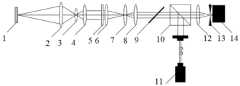
图1是本发明高分辨力立体视觉测量装置的单目测量装置结构示意图。FIG. 1 is a schematic structural diagram of the monocular measurement device of the high-resolution stereo vision measurement device of the present invention.
图1中:1被测样品、2摄影镜头、3场镜II、4物镜、51/4波片、6管镜、7场镜I、8扫描透镜、9二维振镜、10PBS、11激光器、12聚焦透镜、13针孔和14PMT探测器。In Figure 1: 1 sample under test, 2 camera lens, 3 field lens II, 4 objective lens, 51/4 wave plate, 6 tube lens, 7 field lens I, 8 scan lens, 9 2D galvanometer, 10PBS, 11 laser , 12 focusing lenses, 13 pinholes and 14PMT detectors.
图2是本发明高分辨力立体视觉系统的结构示意图。FIG. 2 is a schematic structural diagram of the high-resolution stereoscopic vision system of the present invention.
图2中:15均为高分辨力立体视觉系统的单目测量装置,1为三维被测样品。In Fig. 2: 15 are monocular measurement devices of a high-resolution stereo vision system, and 1 is a three-dimensional measured sample.
具体实施方式Detailed ways
根据本发明的一具体实施例,提供一种高分辨力立体视觉系统,用以三维物体高分辨力成像。According to a specific embodiment of the present invention, a high-resolution stereoscopic vision system is provided, which is used for high-resolution imaging of three-dimensional objects.
请参照图2,图2为本发明高分辨力立体视觉系统的实施例示意图,图2由至少2个高分辨力立体视觉测量单目测量装置组成,图1为高分辨力立体视觉测量单目测量装置实施例示意图。Please refer to FIG. 2, FIG. 2 is a schematic diagram of an embodiment of a high-resolution stereo vision system of the present invention, FIG. 2 is composed of at least two high-resolution stereo vision measurement monocular measurement devices, and FIG. 1 is a high-resolution stereo vision measurement monocular Schematic diagram of the embodiment of the measuring device.
高分辨力立体视觉系统,包括:至少两个单目测量装置15;单目测量装置15对三维被测样品1进行视觉测量;The high-resolution stereo vision system includes: at least two
单目测量装置,包括激光照明模块、视觉摄像模块、扫描放大测量模块;Monocular measurement device, including laser lighting module, visual camera module, scanning magnification measurement module;
激光照明模块按照照明光传播方向依次为:激光器11、PBS10、二维振镜9、扫描透镜8、场镜I7、管镜6、1/4波片5、物镜4、场镜II3和摄影镜头2;The laser illumination module is in order according to the propagation direction of the illumination light:
视觉摄像模块为:摄影镜头2、场镜II3、物镜4、1/4波片5、管镜6、场镜I7、扫描透镜8、二维振镜9、PBS10、聚焦透镜12、针孔13和PMT探测器14;The visual camera module is:
扫描放大测量模块按照信号光传播方向依次为:激光器11、PBS10、二维振镜9、扫描透镜8、场镜I7、管镜6、1/4波片5、物镜4、场镜II3、物镜4、1/4波片5、管镜6、场镜I7、扫描透镜8、二维振镜9、PBS10、聚焦透镜12、针孔13和PMT探测器14;The scanning magnification measurement module is as follows according to the propagation direction of the signal light:
激光照明模块、视觉摄像模块、扫描放大测量模块共用场镜II3、物镜4、1/4波片5、管镜6、场镜I7、扫描透镜8、二维振镜9、PBS10;Laser illumination module, visual camera module, scanning magnification measurement module share field lens II3,
激光照明模块、视觉摄像模块还共用摄影镜头2;The laser lighting module and the visual camera module also share the
激光照明模块、扫描放大测量模块共用激光器11;The laser illuminating module and the scanning amplifying measuring module share the
视觉摄像模块、扫描放大测量模块共用聚焦透镜12、针孔13和PMT探测器14;The visual camera module and the scanning magnification measurement module share the focusing
激光照明模块中激光器11发出激光,准直后形成平行光,经过PBS反射后再经过二维振镜9和扫描透镜8后聚焦于场镜I7光心位置处,光束经过管镜6后形成平行光后经1/4波片5后被物镜4聚焦于场镜II3光心位置,再经摄影镜头2聚焦于三维被测样品1表面形成聚焦光斑,聚焦光斑照射三维被测样品表面的发出反射光;In the laser lighting module, the
三维被测样品1表面发出的反射光依次经过摄影镜头2、场镜II3、物镜4、1/4波片5、管镜6、场镜I7、扫描透镜8、二维振镜9、PBS10和聚焦透镜12、针孔13后被PMT探测器14收集。The reflected light emitted from the surface of the three-
为了进一步优化上述技术方案,立体视觉系统中在定焦摄像镜头后加上扫描放大测量模块用来提高整个系统的等效焦距,提高倍率取决于所选的扫描放大测量模块,从而提高整个立体视觉系统的分辨力。In order to further optimize the above technical solutions, in the stereo vision system, a scanning magnification measurement module is added after the fixed-focus camera lens to improve the equivalent focal length of the entire system. system resolution.
为了进一步优化上述技术方案,立体视觉系统成像方式为振镜扫描成像,扫描放大测量模块的引入提高收集信号的信噪比。In order to further optimize the above technical solution, the imaging mode of the stereo vision system is galvanometer scanning imaging, and the introduction of the scanning magnification measurement module improves the signal-to-noise ratio of the collected signals.
为了进一步优化上述技术方案,立体视觉系统场镜的引入匹配视场从而无需额外的运动扫描机构即可实现全摄像物镜视场成像。In order to further optimize the above technical solution, the introduction of the field lens of the stereo vision system matches the field of view, so that the imaging of the field of view of the full camera objective lens can be realized without an additional motion scanning mechanism.
实现高分辨力立体视觉测量的测量方法,包括以下步骤:The measurement method for realizing high-resolution stereo vision measurement includes the following steps:
步骤a、根据具体需求选择使用几个高分辨力立体视觉单目测量装置组成高分辨力立体视觉系统;Step a. Select and use several high-resolution stereo vision monocular measurement devices to form a high-resolution stereo vision system according to specific requirements;
步骤b、对每一目测量装置进行单目矫正;Step b, performing monocular correction on each eye measurement device;
步骤c、对整体立体视觉系统进行矫正;Step c, correcting the overall stereoscopic vision system;
步骤d、将三维被测样品放置在清晰成像处并对三维被测样品进行成像并计算形貌。In step d, the three-dimensional measured sample is placed at the clear imaging position, and the three-dimensional measured sample is imaged and the shape is calculated.
本发明不局限于上述最佳实施方式,任何人应该得知在本发明的启示下作出的结构变化或方法改进,凡是与本发明具有相同或相近的技术方案,均落入本发明的保护范围之内。The present invention is not limited to the above-mentioned best embodiment, and anyone should know that structural changes or method improvements made under the inspiration of the present invention, any technical solutions that are the same or similar to the present invention, fall into the protection scope of the present invention within.
Claims (2)
Priority Applications (1)
| Application Number | Priority Date | Filing Date | Title |
|---|---|---|---|
| CN201811496736.7ACN109470146B (en) | 2018-12-07 | 2018-12-07 | High-resolution stereo vision system and measuring method |
Applications Claiming Priority (1)
| Application Number | Priority Date | Filing Date | Title |
|---|---|---|---|
| CN201811496736.7ACN109470146B (en) | 2018-12-07 | 2018-12-07 | High-resolution stereo vision system and measuring method |
Publications (2)
| Publication Number | Publication Date |
|---|---|
| CN109470146A CN109470146A (en) | 2019-03-15 |
| CN109470146Btrue CN109470146B (en) | 2020-06-09 |
Family
ID=65675809
Family Applications (1)
| Application Number | Title | Priority Date | Filing Date |
|---|---|---|---|
| CN201811496736.7AExpired - Fee RelatedCN109470146B (en) | 2018-12-07 | 2018-12-07 | High-resolution stereo vision system and measuring method |
Country Status (1)
| Country | Link |
|---|---|
| CN (1) | CN109470146B (en) |
Family Cites Families (7)
| Publication number | Priority date | Publication date | Assignee | Title |
|---|---|---|---|---|
| JP2568388B2 (en)* | 1994-09-15 | 1997-01-08 | シーケーディ株式会社 | Shape measuring device |
| CN1208952C (en)* | 2000-06-19 | 2005-06-29 | 张海涛 | Method and device for improving image definition |
| CN101377410A (en)* | 2008-10-10 | 2009-03-04 | 哈尔滨工业大学 | Large caliber aspheric surface measuring apparatus and method based on ultra-precise revolving scanning |
| CA2763826C (en)* | 2009-06-17 | 2020-04-07 | 3Shape A/S | Focus scanning apparatus |
| KR102214296B1 (en)* | 2014-01-09 | 2021-02-08 | 지고 코포레이션 | Measuring topography of aspheric and other non-flat surfaces |
| CN105891075B (en)* | 2016-04-12 | 2019-01-22 | 中国科学院长春光学精密机械与物理研究所 | A multi-point collaborative laser module and gas detection system |
| CN108036737B (en)* | 2017-12-12 | 2019-11-12 | 南京信息工程大学 | Device and method for full-field lighting snapshot detection of reflective surface shape |
- 2018
- 2018-12-07CNCN201811496736.7Apatent/CN109470146B/ennot_activeExpired - Fee Related
Also Published As
| Publication number | Publication date |
|---|---|
| CN109470146A (en) | 2019-03-15 |
Similar Documents
| Publication | Publication Date | Title |
|---|---|---|
| CN107240148B (en) | Method and device for 3D surface reconstruction of transparent objects based on background schlieren technology | |
| WO2004044522A1 (en) | Three-dimensional shape measuring method and its device | |
| TW200907318A (en) | Eccentricity amount measuring device | |
| CN103363927B (en) | The arbitrary axis of platform electro-optical equipment is apart from multi-light axis consistency pick-up unit and method | |
| CN101231158A (en) | Rapid detection device for three-dimensional shape and size of tiny objects based on liquid zoom lens | |
| CN103180769B (en) | Microscope, image acquiring device and image-taking system | |
| CN104535300B (en) | Large-diameter collimator wavefront and image surface position calibration device and method | |
| CN111521994B (en) | Method and test device for measuring angular resolution and vertical field of view of lidar | |
| CN106017404A (en) | Detection device and method for included angle between visual axis of camera and optical axis of auxiliary laser in image pickup measurement | |
| CN111351437A (en) | Active binocular measurement method and device | |
| JP2015108582A (en) | Three-dimensional measurement method and device | |
| US20200363315A1 (en) | Method for Calibrating an Analysis Device, and Associated Device | |
| CN108318887B (en) | Laser-assisted binocular range finding system | |
| CN204359512U (en) | Wavefront and image surface position calibration device for large-diameter collimator | |
| CN109470146B (en) | High-resolution stereo vision system and measuring method | |
| CN109470147B (en) | Adaptive high-resolution stereo vision system and measurement method | |
| CN110873558B (en) | A measuring device and measuring method for distance and attitude angle | |
| CN109470143B (en) | External light source high-resolution stereo vision measuring system and method | |
| JP2015230209A (en) | Image processor, appearance measuring system, image processing method and system | |
| CN103697825B (en) | Super-resolution 3D laser measurement system and method | |
| KR101901774B1 (en) | Apparatus for inspecting motile of sperm | |
| CN109470144B (en) | Line scan high-resolution stereo vision measurement system and method | |
| CN109596063B (en) | Multi-wavelength high-resolution stereo vision measuring device and method | |
| WO2017045875A1 (en) | An apparatus and a method for encoding an image captured by an optical acquisition system | |
| RU2734070C1 (en) | Method of measuring spatial distance between small objects |
Legal Events
| Date | Code | Title | Description |
|---|---|---|---|
| PB01 | Publication | ||
| PB01 | Publication | ||
| SE01 | Entry into force of request for substantive examination | ||
| SE01 | Entry into force of request for substantive examination | ||
| GR01 | Patent grant | ||
| GR01 | Patent grant | ||
| CF01 | Termination of patent right due to non-payment of annual fee | ||
| CF01 | Termination of patent right due to non-payment of annual fee | Granted publication date:20200609 Termination date:20211207 |