CN1094227C - self-positioning remote monitoring system - Google Patents
self-positioning remote monitoring systemDownload PDFInfo
- Publication number
- CN1094227C CN1094227CCN951959468ACN95195946ACN1094227CCN 1094227 CCN1094227 CCN 1094227CCN 951959468 ACN951959468 ACN 951959468ACN 95195946 ACN95195946 ACN 95195946ACN 1094227 CCN1094227 CCN 1094227C
- Authority
- CN
- China
- Prior art keywords
- control unit
- remote control
- base station
- alarm system
- mentioned
- Prior art date
- Legal status (The legal status is an assumption and is not a legal conclusion. Google has not performed a legal analysis and makes no representation as to the accuracy of the status listed.)
- Expired - Lifetime
Links
Images


Classifications
- G—PHYSICS
- G08—SIGNALLING
- G08B—SIGNALLING OR CALLING SYSTEMS; ORDER TELEGRAPHS; ALARM SYSTEMS
- G08B21/00—Alarms responsive to a single specified undesired or abnormal condition and not otherwise provided for
- G—PHYSICS
- G08—SIGNALLING
- G08B—SIGNALLING OR CALLING SYSTEMS; ORDER TELEGRAPHS; ALARM SYSTEMS
- G08B21/00—Alarms responsive to a single specified undesired or abnormal condition and not otherwise provided for
- G08B21/02—Alarms for ensuring the safety of persons
- G08B21/0202—Child monitoring systems using a transmitter-receiver system carried by the parent and the child
- G08B21/0205—Specific application combined with child monitoring using a transmitter-receiver system
- G08B21/0211—Combination with medical sensor, e.g. for measuring heart rate, temperature
- B—PERFORMING OPERATIONS; TRANSPORTING
- B63—SHIPS OR OTHER WATERBORNE VESSELS; RELATED EQUIPMENT
- B63C—LAUNCHING, HAULING-OUT, OR DRY-DOCKING OF VESSELS; LIFE-SAVING IN WATER; EQUIPMENT FOR DWELLING OR WORKING UNDER WATER; MEANS FOR SALVAGING OR SEARCHING FOR UNDERWATER OBJECTS
- B63C9/00—Life-saving in water
- B63C9/0005—Life-saving in water by means of alarm devices for persons falling into the water, e.g. by signalling, by controlling the propulsion or manoeuvring means of the boat
- G—PHYSICS
- G08—SIGNALLING
- G08B—SIGNALLING OR CALLING SYSTEMS; ORDER TELEGRAPHS; ALARM SYSTEMS
- G08B13/00—Burglar, theft or intruder alarms
- G08B13/02—Mechanical actuation
- G08B13/14—Mechanical actuation by lifting or attempted removal of hand-portable articles
- G08B13/1427—Mechanical actuation by lifting or attempted removal of hand-portable articles with transmitter-receiver for distance detection
- G—PHYSICS
- G08—SIGNALLING
- G08B—SIGNALLING OR CALLING SYSTEMS; ORDER TELEGRAPHS; ALARM SYSTEMS
- G08B19/00—Alarms responsive to two or more different undesired or abnormal conditions, e.g. burglary and fire, abnormal temperature and abnormal rate of flow
- G—PHYSICS
- G08—SIGNALLING
- G08B—SIGNALLING OR CALLING SYSTEMS; ORDER TELEGRAPHS; ALARM SYSTEMS
- G08B21/00—Alarms responsive to a single specified undesired or abnormal condition and not otherwise provided for
- G08B21/02—Alarms for ensuring the safety of persons
- G08B21/0202—Child monitoring systems using a transmitter-receiver system carried by the parent and the child
- G08B21/0222—Message structure or message content, e.g. message protocol
- G—PHYSICS
- G08—SIGNALLING
- G08B—SIGNALLING OR CALLING SYSTEMS; ORDER TELEGRAPHS; ALARM SYSTEMS
- G08B21/00—Alarms responsive to a single specified undesired or abnormal condition and not otherwise provided for
- G08B21/02—Alarms for ensuring the safety of persons
- G08B21/0202—Child monitoring systems using a transmitter-receiver system carried by the parent and the child
- G08B21/0227—System arrangements with a plurality of child units
- G—PHYSICS
- G08—SIGNALLING
- G08B—SIGNALLING OR CALLING SYSTEMS; ORDER TELEGRAPHS; ALARM SYSTEMS
- G08B21/00—Alarms responsive to a single specified undesired or abnormal condition and not otherwise provided for
- G08B21/02—Alarms for ensuring the safety of persons
- G08B21/0202—Child monitoring systems using a transmitter-receiver system carried by the parent and the child
- G08B21/023—Power management, e.g. system sleep and wake up provisions
- G—PHYSICS
- G08—SIGNALLING
- G08B—SIGNALLING OR CALLING SYSTEMS; ORDER TELEGRAPHS; ALARM SYSTEMS
- G08B21/00—Alarms responsive to a single specified undesired or abnormal condition and not otherwise provided for
- G08B21/02—Alarms for ensuring the safety of persons
- G08B21/0202—Child monitoring systems using a transmitter-receiver system carried by the parent and the child
- G08B21/0241—Data exchange details, e.g. data protocol
- G08B21/0247—System arrangements wherein the alarm criteria uses signal strength
- G—PHYSICS
- G08—SIGNALLING
- G08B—SIGNALLING OR CALLING SYSTEMS; ORDER TELEGRAPHS; ALARM SYSTEMS
- G08B21/00—Alarms responsive to a single specified undesired or abnormal condition and not otherwise provided for
- G08B21/02—Alarms for ensuring the safety of persons
- G08B21/0202—Child monitoring systems using a transmitter-receiver system carried by the parent and the child
- G08B21/028—Communication between parent and child units via remote transmission means, e.g. satellite network
- G08B21/0283—Communication between parent and child units via remote transmission means, e.g. satellite network via a telephone network, e.g. cellular GSM
- G—PHYSICS
- G08—SIGNALLING
- G08B—SIGNALLING OR CALLING SYSTEMS; ORDER TELEGRAPHS; ALARM SYSTEMS
- G08B21/00—Alarms responsive to a single specified undesired or abnormal condition and not otherwise provided for
- G08B21/02—Alarms for ensuring the safety of persons
- G08B21/0202—Child monitoring systems using a transmitter-receiver system carried by the parent and the child
- G08B21/0286—Tampering or removal detection of the child unit from child or article
- G—PHYSICS
- G08—SIGNALLING
- G08B—SIGNALLING OR CALLING SYSTEMS; ORDER TELEGRAPHS; ALARM SYSTEMS
- G08B21/00—Alarms responsive to a single specified undesired or abnormal condition and not otherwise provided for
- G08B21/02—Alarms for ensuring the safety of persons
- G08B21/0202—Child monitoring systems using a transmitter-receiver system carried by the parent and the child
- G08B21/0288—Attachment of child unit to child/article
- G—PHYSICS
- G08—SIGNALLING
- G08B—SIGNALLING OR CALLING SYSTEMS; ORDER TELEGRAPHS; ALARM SYSTEMS
- G08B21/00—Alarms responsive to a single specified undesired or abnormal condition and not otherwise provided for
- G08B21/02—Alarms for ensuring the safety of persons
- G08B21/0202—Child monitoring systems using a transmitter-receiver system carried by the parent and the child
- G08B21/0294—Display details on parent unit
- G—PHYSICS
- G08—SIGNALLING
- G08B—SIGNALLING OR CALLING SYSTEMS; ORDER TELEGRAPHS; ALARM SYSTEMS
- G08B21/00—Alarms responsive to a single specified undesired or abnormal condition and not otherwise provided for
- G08B21/02—Alarms for ensuring the safety of persons
- G08B21/08—Alarms for ensuring the safety of persons responsive to the presence of persons in a body of water, e.g. a swimming pool; responsive to an abnormal condition of a body of water
- G08B21/088—Alarms for ensuring the safety of persons responsive to the presence of persons in a body of water, e.g. a swimming pool; responsive to an abnormal condition of a body of water by monitoring a device worn by the person, e.g. a bracelet attached to the swimmer
- G—PHYSICS
- G08—SIGNALLING
- G08B—SIGNALLING OR CALLING SYSTEMS; ORDER TELEGRAPHS; ALARM SYSTEMS
- G08B25/00—Alarm systems in which the location of the alarm condition is signalled to a central station, e.g. fire or police telegraphic systems
- G08B25/01—Alarm systems in which the location of the alarm condition is signalled to a central station, e.g. fire or police telegraphic systems characterised by the transmission medium
- G08B25/10—Alarm systems in which the location of the alarm condition is signalled to a central station, e.g. fire or police telegraphic systems characterised by the transmission medium using wireless transmission systems
- G—PHYSICS
- G08—SIGNALLING
- G08B—SIGNALLING OR CALLING SYSTEMS; ORDER TELEGRAPHS; ALARM SYSTEMS
- G08B26/00—Alarm systems in which substations are interrogated in succession by a central station
- G08B26/007—Wireless interrogation
- G—PHYSICS
- G08—SIGNALLING
- G08B—SIGNALLING OR CALLING SYSTEMS; ORDER TELEGRAPHS; ALARM SYSTEMS
- G08B25/00—Alarm systems in which the location of the alarm condition is signalled to a central station, e.g. fire or police telegraphic systems
- G08B25/007—Details of data content structure of message packets; data protocols
Landscapes
- Physics & Mathematics (AREA)
- General Physics & Mathematics (AREA)
- Health & Medical Sciences (AREA)
- General Health & Medical Sciences (AREA)
- Child & Adolescent Psychology (AREA)
- Business, Economics & Management (AREA)
- Emergency Management (AREA)
- Engineering & Computer Science (AREA)
- Computer Networks & Wireless Communication (AREA)
- Ocean & Marine Engineering (AREA)
- Cardiology (AREA)
- Heart & Thoracic Surgery (AREA)
- Mechanical Engineering (AREA)
- Alarm Systems (AREA)
- Emergency Alarm Devices (AREA)
- Mobile Radio Communication Systems (AREA)
Abstract
Description
Translated fromChinese技术领域technical field
本发明涉及个人报警系统,特别是涉及在紧急情况期间发送较高功率电平的信号的这样的系统。The present invention relates to personal alarm systems, and in particular to such systems that transmit higher power level signals during emergency situations.
背景技术Background technique
本领域中众所周知一些个人报警系统(例如,参见美国专利US4,777,478;US5,025,247;US5,115,223;US4,952,928;US4,819,860;US4,899,135;US5,047,750;US4,785,291;US5,043,702;及US5,086,391)。这些系统用来保持监视儿童。用它们在远距离位置监控涉及危险工作的雇员的安全。甚至用它们来寻找丢失或被盗的车辆及迷路的宠物。Some personal alarm systems are well known in the art (see, for example, U.S. Patents US 4,777,478; US 5,025,247; US 5,115,223; and US5,086,391). These systems are used to keep children under surveillance. Use them to monitor the safety of employees involved in hazardous work at remote locations. Even use them to find lost or stolen vehicles and stray pets.
这些系统采用无线电技术把一个遥控发射单元与一个基地接收和监控电台连系起来。遥控单元通常配备有一个或多个事故传感器,并佩带或附着在要被监控的人或物上。当检测到事故时,遥控单元就给接收基地电台发射信号,在基地电台处的工作者就可以对事故作出反应而采取适当的行动。These systems use radio technology to link a remote control transmitter unit with a base receiving and monitoring station. The remote control unit is usually equipped with one or more incident sensors and is worn or attached to the person or thing to be monitored. When an accident is detected, the remote unit transmits a signal to the receiving base station, and the operator at the base station can respond to the accident and take appropriate action.
采用个人报警系统来监控儿童已日益变得更加普遍。看管人把一个不大于个人寻呼机的小型遥控单元附着在小孩的外衣上。如果小孩走丢了或遇到可探测到的危险,看管人立刻就可以知晓并且开始帮助小孩。在至少一种有益的用途,遥控单元包括一个接收机和一个可由小型手持发射机驱动的可听得到的报警器。这报警器系在小孩身上。如果小孩在一大堆人群中(例如,在一个百货商场中)走失,看管人就启动可听得到的报警器,这报警器然后就发出一系列对于确定孩子的位置有用的“嘟嘟声”,方式就如同人们用一个汽车报警系统在一个停车场寻找汽车一样。The use of personal alarm systems to monitor children has become increasingly more common. Caretakers attach a small remote control unit, no larger than a personal pager, to the child's outerwear. If a child is lost or in detectable danger, the caretaker knows immediately and can begin to help the child. In at least one advantageous use, the remote control unit includes a receiver and an audible siren actuated by a small hand-held transmitter. The alarm is attached to the child. If a child gets lost in a large crowd (for example, in a department store), the caretaker activates an audible siren, which then emits a series of "beeps" useful for locating the child , in the same way that people use a car alarm system to find cars in a parking lot.
个人报警系统中已经包括有大量的新的特征。Hirsh等人的美国专利US4,777,478中提供了一个由孩子启动的恐慌按钮,或者,如果有人试图从孩子的衣服上移走遥控单元就发出警报。Banks的美国专利US5,025,247揭示了一种锁住报警状态的基地电台,从而使得一旦发出警报,在得到帮助之前,遥控单元的失灵不会导致关闭警报。Moody的美国专利US5,115,223揭示了利用沿轨道运行的卫星和三角测量来限定寻找已发出警报的遥控单元的区域。在Carroll等人的美国专利US4,952,928和Hargrove等人的美国专利US4,819,860中的装置提供了用于遥控监视并不局限于一些固定位置的人的一些极其重要的标记。A large number of new features have been included in the personal alarm system. US Pat. No. 4,777,478 to Hirsh et al. provides a panic button activated by the child, or an alarm if someone tries to remove the remote control unit from the child's clothing. US Patent No. 5,025,247 to Banks discloses a base station that latches on to the alarm state so that once the alarm is sounded, failure of the remote control unit does not result in the alarm being turned off until assistance is obtained. US Patent No. 5,115,223 to Moody discloses the use of orbiting satellites and triangulation to define the area to look for an alarmed remote unit. The devices in US Pat. No. 4,952,928 to Carroll et al. and US Pat. No. 4,819,860 to Hargrove et al. provide some extremely important markers for remote monitoring of persons not confined to some fixed location.
Ghahariiran的美国专利US4,899,135中揭示了一种儿童监控装置,如果孩子越出了范围或掉进水中,这种儿童监控装置就用无线电频率或超声波频率发出警报。Hawthorne的美国专利US4,785,291揭示了一种远距离监控器,用于监控儿童,其中,由儿童佩带的一个单元包括一个无线电发射机。当孩子走出范围时,所接收到的、由孩子身上的那个单元发出的信号的场强下降到一个限度以下,并发出警报。US Patent No. 4,899,135 to Ghahariiran discloses a child monitoring device that uses radio frequency or ultrasonic frequency to sound an alarm if the child goes out of range or falls into the water. US Patent No. 4,785,291 to Hawthorne discloses a remote monitor for monitoring children in which a unit worn by the child includes a radio transmitter. When the child goes out of range, the field strength of the received signal from the unit on the child falls below a limit and an alarm is sounded.
我们医院的急诊室中的临床经验告诉我们,有限数量的共同的一些事故占到了我们的蹒跚走路的年龄的孩子的可预防的伤害和死亡的大多数。这些事故包括孩子走出安全区域或被监视的区域而迷失、落入水中、失火、吸入烟气、一氧化碳中毒和电击。诸如上述那些儿童监控装置在减少涉及到这些共同的可预防的事故的伤害和死亡的数量方面是有效的。Clinical experience in our hospital emergency rooms tells us that a limited number of common accidents account for the majority of preventable injuries and deaths in our toddler-age children. These incidents include children getting lost outside a safe or monitored area, falling into water, fire, smoke inhalation, carbon monoxide poisoning and electric shock. Child monitoring devices such as those described above are effective in reducing the number of injuries and deaths involved in these commonly preventable accidents.
不过,考虑到我们的儿童的安全的重要性,仍留有改进这些系统的余地。一个这样的要改进的方面涉及延长电池的使用寿命,这电池当呼叫这些蹒跚走路的孩子的遥测系统的遥控单元时给该遥控单元供电。However, given the importance of our children's safety, there is still room for improvement in these systems. One such area for improvement involves extending the life of the battery that powers the remote control unit of the toddler's telemetry system when calling the remote control unit.
遥控单元一般由电池驱动,并且对于紧急情况,仍就由电池驱动,而用于现场报警和寻找方向的可靠地发射信号是头等重要的。换言之,一旦检测到事故并发出警报,关键的是遥控单元不断发射信号,从而可用定向装置定出孩子的位置。The remote control unit is generally battery-driven, and for emergency situations, it is still battery-driven, and reliable transmission of signals for on-site alarms and finding directions is of paramount importance. In other words, once an accident is detected and an alarm is issued, it is crucial that the remote control unit continuously transmits signals so that the child's location can be determined by the directional device.
儿童监控系统的遥控单元一般相当小,因而电池可资利用的空间相当有限。尽管近来电池方面的技术有进展,电池的使用寿命还是与电池尺寸有关。例如,较大的“D”号电池比小得多且轻得多的“AAA”号电池使用时间长得相当多。尽管采用电能消耗极低的电子线路已使得可能使用更小的电池,电池的使用寿命仍就是极为制约它的物理尺寸的一个因素,如上所述,该物理尺寸因为一般的遥控单元的小迟寸而受到限制。因此,另外要努力减少电池耗电是重要的。The remote control units of child monitoring systems are generally quite small, so the space available for batteries is quite limited. Despite recent advances in battery technology, battery life is still related to battery size. For example, a larger "D" size battery will last considerably longer than a much smaller and lighter "AAA" size battery. Although the use of electronic circuits with extremely low power consumption has made it possible to use smaller batteries, the service life of the battery is still a factor that greatly restricts its physical size. And be restricted. Therefore, it is important to make additional efforts to reduce battery drain.
对于任何儿童监控系统的可靠性如果更可依赖的话,就愿意在无危险时使遥控单元以小功率发射信号或根本不发射信号。If more dependable on the reliability of any child monitoring system, it would be desirable to have the remote control unit transmit a signal at low power or not at all when there is no danger.
关于这篇部分后续申请的另外一些所感兴趣的美国专利包括:US3,646,583;US3,784,842;US3,828,306;US4,216,545;US4,598,272;US4,656,463;US4,675,656;US5,043,736;US5,223,844;US5,311,197;US5,234,974;US5,378,865。Other US patents of interest for this partial continuation include: US3,646,583; US3,784,842; US3,828,306; US4,216,545; US4,598,272; 223,844; US5,311,197; US5,234,974; US5,378,865.
发明内容Contents of the invention
本发明的一个目的是提供一种个人报警系统,其中,由电池驱动的遥控单元正常情况下以小功率发射信号,而当该遥控单元和基地电台之间的距离超过一个预定限度时就转换为以更大的功率发射信号。It is an object of the present invention to provide a personal alarm system in which the battery-operated remote unit normally transmits at a low power level and switches to Transmit a signal with greater power.
本发明还有一个目的是提供这样的一种系统,这种系统包括一些传感器,这些传感器用于一般是年轻的儿童所遇到的危险情况。Yet another object of the present invention is to provide such a system including sensors for use in hazardous situations typically encountered by young children.
本发明的一个进一步的目的提供这样一种个人报警系统,这种系统包括一种在遥控单元和基地电台之间的定期信号交换的交换机,以便表明该系统在不断工作。It is a further object of the present invention to provide such a personal alarm system which includes a switch for periodic handshaking between the remote unit and the base station to indicate that the system is constantly operating.
按照本发明的上述目的及下面将会显然看出的那些目的,提供了一种个人报警系统,这种个人报警系统包括:In accordance with the above objects of the present invention and those that will become apparent hereinafter, there is provided a personal alarm system comprising:
一个遥控单元,这个遥控单元包括无线电发射装置和无线电接收装置;A remote control unit, the remote control unit includes a radio transmitter and a radio receiver;
该遥控单元发射装置能以高于一个功率电平发射信号,并确定一个更高的功率电平;The remote control unit transmitting means is capable of transmitting signals at a power level higher than one and determines a higher power level;
一个基地电台,这个基地电台包括无线电发射装置和无线电接收装置;a base station, the base station including radio transmitters and radio receivers;
所述遥控单元和基地电台进行无线电通信,并确定在该遥控单元和基地电台之间所分开的距离;said remote unit is in radio communication with a base station and determining a separation distance between the remote unit and the base station;
用于确定上述分开的距离是否超过一个预定的限度的度量装置;Measuring means for determining whether said separation distance exceeds a predetermined limit;
响应于上述度量装置的装置,用于当上述分开的距离超过所述限度时使上述遥控单元发射装置以更高的功率电平发射信号;以及means, responsive to said measuring means, for causing said remote control unit transmitting means to transmit at a higher power level when said separation distance exceeds said limit; and
用于指示上述分开的距离超过所述限度时的报警装置。An alarm device for indicating that the above separation distance exceeds the stated limit.
在本发明的一个实施例中,基地电台发射定期的终端设备定时询问信号,而遥控单元监控所接收到的终端设备定时询问信号的场强。如果所接收到的场强低于某一相应于在两个装置之间的某一最大距离的限度,那么,遥控单元以大功率发射信号。以大功率发射的信号表明是以大功率进行发射信号。当基地电台收到该信号时,就发出警报。还把遥控单元装备成能检测一种或多种事故。In one embodiment of the invention, the base station transmits periodic terminal equipment timing interrogation signals, and the remote control unit monitors the field strength of the received terminal equipment timing interrogation signals. If the received field strength is below a certain limit corresponding to a certain maximum distance between the two devices, then the remote control unit transmits a signal with high power. A signal transmitted at high power indicates that the signal was transmitted at high power. When the base station receives this signal, it sounds an alarm. The remote control unit is also equipped to detect one or more accidents.
在本发明的另一个实施例中,有多个遥控单元,每一个遥控单元通过在其发射的信号中包括一个单元监别号码就能监别其本身。把遥控单元装备成能检测一种或多种事故,并且在它的发射信号中监别所检测到的事故。基地电台能显示发射单元监别号码及任何所检测到的危险的类型。In another embodiment of the invention, there are a plurality of remote units, each remote unit being able to identify itself by including a unit identification number in its transmitted signal. The remote unit is equipped to detect one or more incidents and to detect detected incidents in its transmitted signal. The base station can display the transmitter unit identification number and the type of any hazard detected.
在另一个实施例中,基地电台而不是遥控单元测量所接收到的遥控单元发射信号的场强,并当所接收的场强低于一个预置的限度时指示遥控单元以大功率发射信号。In another embodiment, the base station, instead of the remote unit, measures the received field strength of the remote unit transmission and instructs the remote unit to transmit at high power when the received field strength is below a preset limit.
在另一个实施例中,遥控单元包括能见信标发射机及听得到的信标发射机,可由基地电台启动这些信标发射机,用于确定孩子的位置。In another embodiment, the remote control unit includes visible and audible beacon transmitters that can be activated by the base station for determining the child's location.
在另一个实施例中,遥控单元包括一个恐慌按钮,孩子或所涉及的人可用该按钮召来帮助。In another embodiment, the remote control unit includes a panic button that the child or person involved can use to summon help.
在另一个实施例中,基地电台有能力通过公共电话系统打电话,例如,通过启动寻呼机通信,以便向不在场的看管人发出警报。In another embodiment, the base station has the capability to make calls through the public telephone system, for example, by initiating pager communications to alert an absent caretaker.
在另一个实施例中,遥控单元包括一个全球定位系统(“GPS”)接收机,如果检测到事故,或者如果儿童走失得距基地电台太远,就启动该全球定位系统接收机。然后,遥控单元从GPS接收机发射全球定位座标信号。这些座标由基地电台接收,并用来确定孩子的位置。在一个可供选择的实施例中,遥控单元系在孩子、宠物或车辆上,而由来自基地电台的命令启动GPS接收机。然后,基地电台工作者用全球定位座标来确定遥控单元的位置。In another embodiment, the remote control unit includes a global positioning system ("GPS") receiver that is activated if an accident is detected, or if a child strays too far from the base station. The remote control unit then transmits a global positioning coordinate signal from the GPS receiver. These coordinates are received by the base station and used to determine the child's location. In an alternative embodiment, the remote unit is strapped to the child, pet or vehicle, and the GPS receiver is activated by commands from the base station. The base station operator then uses the global positioning coordinates to determine the location of the remote unit.
在另一个实施例中,遥控单元用一个在远距离位置处做危险工作的雇员佩带,例如,由一个正在修理高压电线的巡线工佩带。遥控单元装备有一个GPS接收机和一个电击事故传感器,并且在发生电击时,遥控单元即时发送出工人位置的信号。该装置使得急救医务人员找到并帮助受伤的工人,而且可能拯救生命。In another embodiment, the remote control unit is worn by an employee doing hazardous work at a remote location, for example, by a lineman repairing high voltage power lines. The remote control unit is equipped with a GPS receiver and an electric shock accident sensor, and in the event of an electric shock, the remote control unit instantly sends out a signal of the worker's location. The device allows emergency medical personnel to locate and assist injured workers, potentially saving lives.
本发明的一个优点是通过交换电子交换信号并在出现事故时发出警报来定期检验系统的完整性。An advantage of the present invention is the periodic verification of the integrity of the system by exchanging electronic handshake signals and sounding alarms in the event of incidents.
本发明的另一个优点是通过在无明确的紧急情况时以小功率发射信号来延长遥控单元电池的寿命。Another advantage of the present invention is to extend the battery life of the remote control unit by transmitting at low power when there is no clear emergency.
本发明的又一个优点是系统能检测出大量普通的和危险的事故并发出警报。Yet another advantage of the present invention is that the system is capable of detecting and alerting a large number of common and dangerous incidents.
本发明还有一个优点是使得能快速并准确地确定装备有一个GPS接收机的遥控单元的位置。Yet another advantage of the present invention is that it enables rapid and accurate determination of the position of a remote control unit equipped with a GPS receiver.
附图说明Description of drawings
图1是本发明的一个实施例的、并以可选择的功率电平发射信号的、一个个人报警系统的方框图。Figure 1 is a block diagram of a personal alarm system that transmits signals at selectable power levels in accordance with one embodiment of the present invention.
图2是包括多个遥控单元的、图1所示的个人报警系统的另一个实施例的方框图。FIG. 2 is a block diagram of another embodiment of the personal alarm system shown in FIG. 1 including multiple remote control units.
图3是说明本发明的个人报警系统的另一个实施例的方框图。Figure 3 is a block diagram illustrating another embodiment of the personal alarm system of the present invention.
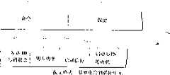
图4是说明图2所示个人报警系统所用的一种优选的通信形式的直观图。FIG. 4 is a schematic diagram illustrating a preferred form of communication for the personal alarm system shown in FIG. 2. FIG.
图5是说明图2所示的个人报警系统所用的另一种优选的通信形式的直观图。FIG. 5 is a schematic diagram illustrating another preferred form of communication for the personal alarm system shown in FIG. 2. FIG.
图6是说明采用全球定位系统以便改进遥控单元寻找位置的、本发明的个人报警系统的一个实施例的方框图。Figure 6 is a block diagram illustrating one embodiment of the personal alarm system of the present invention employing the global positioning system for improved location finding by the remote control unit.
图7是说明典型地应用于监控孩子时图1的个人报警系统的基地电台和遥控单元的直观图。FIG. 7 is a schematic diagram illustrating the base station and remote control unit of the personal alarm system of FIG. 1 in a typical application for monitoring children.
图8是说明带在腰上的、本发明的一个遥控单元的直观图。Fig. 8 is a perspective view illustrating a remote control unit of the present invention worn on the waist.
图9是说明用于从一车辆电气系统操纵的一个本发明的移动式基地电台的直观图。Figure 9 is a schematic diagram illustrating a mobile base station of the present invention for operation from a vehicle electrical system.
图10是说明由普通的家用电源驱动的、本发明的一个基地电台的直观图。Figure 10 is a schematic diagram illustrating a base station of the present invention driven by conventional household power.
图11是说明按照本发明的一个方面的一个人员落水报警系统的方框图。Figure 11 is a block diagram illustrating a man overboard alarm system in accordance with an aspect of the present invention.
图12是说明人员落水报警系统的另一个实施例的方框图。Figure 12 is a block diagram illustrating another embodiment of a man overboard warning system.
图13是说明按照本发明的另一方面的一种不可见的电子篱笆监控系统的方框图。Figure 13 is a block diagram illustrating an invisible fence monitoring system according to another aspect of the present invention.
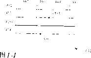
图14是说明用于与图13的不可见的电子篱芭系统一起使用的、确定地理区域的一条边界的直观图。FIG. 14 is a diagram illustrating a boundary for defining a geographic area for use with the invisible electronic fence system of FIG. 13 .
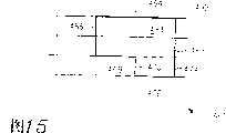
图15是说明一个具有封闭的边界的被确定的区域的另一直观图。Figure 15 is another schematic diagram illustrating a defined region with closed boundaries.
图16是说明包括被确定的一些子区域的一个被确定的区域的另一直观图。Fig. 16 is another diagram illustrating a determined area including determined sub-areas.
图17是说明不可见的电子篱芭系统的另一方面的方框图。FIG. 17 is a block diagram illustrating another aspect of an invisible electric fence system.
图18是说明按照本发明的另一方面的一个固定位置的环境传感系统的方框图。Figure 18 is a block diagram illustrating a fixed location environmental sensing system according to another aspect of the present invention.
图19是包括导航定位在内的一个个人报警系统的方框图,其中,在基地电台处进行精确计算出来的结果的几何图形显示(geometricdillusion)。Fig. 19 is a block diagram of a personal alarm system including navigational positioning, where a geometric illustration of the results of precise calculations is performed at the base station.
图20是说明一个不可见的电子篱笆报警系统的方框图,其中,电子篱笆存储在基地电台处并在基地电台处被比较。Figure 20 is a block diagram illustrating an invisible fence warning system in which the fence is stored at the base station and compared at the base station.
具体实施方式Detailed ways
参照图1,其中示出了按照本发明的一个实施例的个人报警系统的方框图,且一般用标号10来表示。个人报警系统包括一个遥控单元12和一个基地电台14。遥控单元12有一个无线电发射机16和一个接收机18,而基地电台14有一个无线电发射机20和一个接收机22。发射机16、20和接收机18、22适合于在遥控单元12和基地电台14之间进行双向无线电通信。Referring to FIG. 1, there is shown a block diagram, generally designated 10, of a personal alarm system in accordance with one embodiment of the present invention. The personal alarm system includes a
在一个优选实施例中,基地电台14包括一个间隔计时器24,间隔计时器24使发射机20按预定的间隔发射信号。遥控单元12的接收机18接收由基地电台14发射的信号,并使发射机16发射一个响应信号,以便完成电子信号交换。In a preferred embodiment,
遥控单元发射机16能够以保持低功率电平的能量或在紧急情况以高功率电平发射信号。当在遥控单元12和基地电台14之间的距离超过一个预定限度时,遥控就以高功率电平反应。The remote
要完成移到更高的功率电平,遥控单元接收机18产生一个信号26,信号26正比于所接收到的由基地电台14发射的信号的场强。遥控单元12包括一个比较器28,比较器28把场强信号26的大小与一个预定的极限值30比较,并产生一个控制信号32。To accomplish the shift to a higher power level, the
遥控单元发射机16响应于电路34,用于选择是以低功率电平或是以高功率电平发射信号。电路34接通控制信号32,并在所接收的场强等于或超过极限值30时,选择以低功率电平发射信号,而在所接收的场强小于极限值30时,选择以更高的功率电平发射信号。可以选择地,遥控单元发射机16以许多可选择的发射功率电平发射信号。在另一个可供选择的实施例中,可在一个连续的发射功率电平范围内选择进行发射信号。
在个人报警系统10的工作范围内,当在遥控单元12处接收时,基地电台14发射的信号的场强(近似)正比于在两个单元之间的距离的四次方。这个距离定义了‘分开的距离’,并且选择预定的极限值30,以便在上述工作范围内、在所想要的分开的距离处、以更高的功率电平发射信号。Within the operating range of the
在另一个实施例中,遥控12包括一个与发射机16连接的事故传感器36。选择事故传感器,以便检测下述这些普通事故中的一种,这些普通事故有:落水、失火、吸入烟雾、一氧化炭浓度过量及电击。在一个实施例中,被检测到的事故使得遥控单元12发射信号,该信号在检测到危险情况时报告出现危险情况。在另一个实施例中,当出现对于定期电子信号交换的反应时,就报告危险情况。In another embodiment,
在一个实施例中,基地电台14包括一个由接收机22启动的、可听到的报警器38。如果遥控单元没有完成电子信号交换、或报告了被检到的事故、或者通过发送适当的电码指出它越出范围了,则基地电台报警器38就被启动,以便给工作者发出警报。In one embodiment,
图2是说明本发明的个人报警系统的另一个实施例的方框图。一般用标号40表明报警系统,该报警系统包括一个第一遥控单元42、一个第二遥控单元44和一个基地电台46。第一遥控单元42包括一个发射机48、一个接收机50、一个鉴别号码52、一个被接收的场强信号54、一个比较器56、一个预定的极限值58、一个控制信号60、一个功率电平选择电路62和一个事故传感器64。Figure 2 is a block diagram illustrating another embodiment of the personal alarm system of the present invention. The alarm system is indicated generally at 40 and includes a first remote control unit 42 , a second remote control unit 44 and a base station 46 . The first remote control unit 42 includes a transmitter 48, a receiver 50, an identification number 52, a received field strength signal 54, a comparator 56, a predetermined limit value 58, a control signal 60, a power supply Level selection circuit 62 and an accident sensor 64.
第二遥控单元44包括一个单独的鉴别号码66,但是,其它方面与第一遥控单元42相同。The second remote control unit 44 includes a separate identification number 66 but is otherwise the same as the first remote control unit 42 .
基地电台46包括一个发射机68、一个间隔计时器70、一个接收机72、一个报警器74和一个ID状态显示器76。Base station 46 includes a transmitter 68 , an interval timer 70 , a receiver 72 , an alarm 74 and an ID status display 76 .
在图2所示的本发明的一个实施例中,在第一遥控单元42和基地电台46之间的无线电传送信号包括鉴别号码52。在第二遥控单元44和基地电台46之间的传送信号包括鉴别号码66。本领域普通技术人员应该了解,该系统可包括一个或多个遥控单元,每个有一个不同的鉴别号码52。In one embodiment of the invention shown in FIG. 2, the radio transmission signal between the first remote unit 42 and the base station 46 includes an identification number 52. Transmissions between the second remote control unit 44 and the base station 46 include an identification number 66 . Those of ordinary skill in the art will appreciate that the system may include one or more remote control units, each having a different identification number 52 .
还应该了解,每个遥控单元42可有一个不同的预定极限值58。极限值58确定了在遥控单元42和基地电台46之间的一段距离,超过这段距离,该遥控单元就以它的更高的功率电平发射信号。如果用大量遥控单元监控一群儿童,例如,就在学校操场上,可把每个遥控单元的极限值置定在这样一个值,如果儿童越出操场区域,这个值就会导致大功率发射信号。在其它一些应用中,可把每个遥控单元42的极限值置于对应一些不同的距离的一个不同的值,在这些不同的距离处,各个遥控单元就会转换到大功率发射信号。It should also be understood that each remote control unit 42 may have a different predetermined limit value 58 . Limit value 58 defines the distance between remote unit 42 and base station 46 beyond which the remote unit transmits at its higher power level. If a large number of remote units are used to monitor a group of children, for example, right on a school playground, the limit value of each remote unit can be set at a value that will result in a high power transmission if the children move outside the playground area. In other applications, the threshold for each remote unit 42 could be set to a different value corresponding to different distances at which each remote unit would switch to a high power transmit signal.
在一个实施命名,无论何时,遥控单元以大功率发射信号或报告检测到事故,基地电台46就发出警报74。基地电台把报告遥控单元的鉴别号码和事故类型的指示显示在ID状态显示器76上。工作人员可利用这信息,例如,一个日班工作者可利用这信息来决定作出什么反应合适以及是否需要立刻通知看管人。如果一个孩子只是越出了范围,工作者可以只是派出一个同事找到这个孩子,并使她回到游乐区。另一方面,一个落水事故的指示应该立刻迅速地通知看管人和急救人员,并且日班雇员立即行动。In one implementation, the base station 46 issues an alarm 74 whenever the remote unit transmits a signal at high power or reports the detection of an accident. The base station displays on the ID status display 76 the identification number of the reporting remote unit and an indication of the type of accident. Staff can use this information, for example, a day shift worker can use this information to decide what response is appropriate and whether a caretaker needs to be notified immediately. If a child simply strays out of bounds, the worker can simply send a colleague to find the child and bring her back to the play area. On the other hand, the indication of an overboard accident should immediately and promptly notify the caretaker and first responders, and the day shift employees should act immediately.
在另一个实施例中,遥控单元接收机50确定在遥控单元42和基地电台46之间的分开的距离超过预定的阈值。遥控单元发射机48发射电码或状态代码,以便指出那个事实。In another embodiment, the remote unit receiver 50 determines that the separation distance between the remote unit 42 and the base station 46 exceeds a predetermined threshold. The remote control unit transmitter 48 transmits a code or status code to indicate that fact.
在图1所示的实施例中,由基地电台14定期发射的终端设备定时询问信号是RF载波。发射载波频率信号,直到从遥控单元12收到答复,或者直到监视计时器(未示出)暂停,导致报警。遥控单元回答中所含的信号必须包括是以小功率还是以大功率发射信号、以及是否已检测到事故,因为基地电台在这些例子中都报了警。In the embodiment shown in FIG. 1, the terminal equipment timing interrogation signal periodically transmitted by the
不过,在图2所示的实施例中,必须报告另外的信息,而数字化形式的遥控单元的回答的优点对本领域普通技术人员来说是显而易见的。However, in the embodiment shown in Figure 2, additional information must be reported, and the advantages of the remote unit's answer in digitized form will be apparent to those of ordinary skill in the art.
图3是说明本发明的个人报警系统的另一实施例的方框图,且一般用标号80标明。个人报警系统80包括一个遥控单元82和一个基地电台84。FIG. 3 is a block diagram illustrating another embodiment of the personal alarm system of the present invention and generally designated by the numeral 80 . The
遥控单元82包括一个发射机86、一个接收机88、一个功率电平选择电路90、一个ID号码92,一个能见信标发射机94、一个听得到的信标发射机96、一个监视计时器98、许多事故传感器100、一个紧急开关(“恐慌按钮”)112、一个电池113以及一个‘低电池功率’传感器114,所述许多事故传感器包括一个人员落水传感器102、一个烟雾传感器104、一个热传感器106、一个一氧化碳传感器108、一个干预开关109以及一个电击传感器110。The
基地电台84包括一个发射机116、一个产生所接收的场强信号120的接收机118、一个比较器122、一个预定的极限值124、一个比较器输出信号126、一个间隔计时器128、控制信号130和132、一个可视报警器134、一个听得到的报警器136、一个ID和状态显示器138、一个用于启动电话并把通讯线路142接到公用电话系统的电路140。The
图3中的实施例所说明的基地电台84和许多遥控单元82用数字化形式的通信来进行交流。基地电台84用一种报文格式,以便命令一个特定的遥控单元82,而被命令的遥控单元82用第二种报文格式,以便答复基地电台84。图5和图4分别说明了这些报文格式。The embodiment illustrated in FIG. 3 communicates between a
参照图4,图4显示了用于本发明的个人报警系统中的遥控单元所发出的响应信号的、一种优选的数字化形式的直观图,一般用标号150标明这个数字响应信号形式。数字响应信号形式150包括一个遥控单元号码152、许多事故传感器状态代码154,这许多事故传感器状态代码154包括人员落水状态代码156、烟雾传感器状态代码158、热传感器状态代码160、过量一氧化碳浓度状态代码162以及电击状态代码164。响应信号150还包括大功率状态代码166、恐慌按钮状态代码168、低电池功率检测器状态代码170、干预开关状态代码171和为将来的那些用途所保留的状态代码172。Referring to FIG. 4, there is shown a schematic diagram of a preferred digital form of the response signal sent by the remote control unit used in the personal alarm system of the present invention, generally indicated by reference numeral 150. This digital response signal form. The digital response signal form 150 includes a remote unit number 152, a number of accident sensor status codes 154 including a man overboard status code 156, a smoke sensor status code 158, a heat sensor status code 160, an excess carbon monoxide concentration status code 162 and Shock Status Code 164. Response signal 150 also includes high power status code 166, panic button status code 168, low battery power detector status code 170, tamper switch status code 171 and status code 172 reserved for those future uses.
图5是用于基地电台到遥控单元传输信号的一种优选的数字形式的直观图,一般用标号180标明。数字报文格式180包括一个命令信息组182和许多保留下来用于未来用途的未指定的比特190。命令信息组182包括一个编码的比特的信息组184,这个信息组184用来命令一个特定的遥控单元,以便发射它的响应信息(用形式150)。命令信息组182还包括一个用来命令遥控单元的单个的比特,就如图3所示的实施例那样,以便以大功率发射信号。命令信息组182包括命令比特188,比特188用来命令遥控单元启动信标发射机,例如,图3所示的能见信标发射机94和听得到的信标发射机96。命令信息组182还包括命令比特189,比特189用来命令遥控单元启动GPS接收机,就如图6所示的那样。FIG. 5 is a schematic diagram, generally indicated by the
在一个可供选择的实施例中,遥控单元发射机适于以许多发射功率电平中的一个发射信号,并且用多比特命令子信息组取代单个的命令比特186,用于选择一个功率电平。在另一个实施例中,遥控单元发射机适于以从一连续的功率电平中选出的一个功率电平发射信号,并提供多比特子信息组,用于选择功率电平。In an alternative embodiment, the remote control unit transmitter is adapted to transmit at one of a number of transmit power levels, and the
再次参照图3,基地电台84通过发出命令180要求遥控单元82以报文格式150响应,来定期对每个遥控单元82进行终端设备定时询问。为清楚起见,当必需时,会采用对于上述格式或被发送的信息的专门的说明。就像通讯工业通常所做的那样,信息有时叫作‘信号’,而在另一些场合叫作‘发射信号’和‘报文’,为清楚起见,当必需时,会区别它们。Referring again to FIG. 3, the
所有的遥控单元接收报文180,该报文所直对的遥控单元(利用编码的信息组184)通过发出它的鉴别号码152和当前的状态代码154至170来响应。为此目的,遥控单元鉴别号码92接通发射机86。All remote units receive the
在图3所示的实施例中,在基地电台84处完成测量所接收的场强的任务,以便确定是否超过预定的分开的距离。基地电台接收机118所接收的场强信号120,信号120接通比较器122。预定的极限值124也接通提供比较器输出信号126的比较器122。如果所接收的场强120小于极限值124,比较器输出信号126就接通,以便在基地单元84发出的报文180中认定“转向大功率”的命令比特186。选择极限值,以便确立预定的分开的距离,超出这个预定的分开的距离,就命令以大功率发射信号。In the embodiment shown in FIG. 3, the task of measuring the received field strength is performed at the
在一个实施例中,通过由制造者把极限值124输入只读存储器装置来完成选择极限值124。在另一个实施例中,制造者用手动开关选择预定的极限值124。在另一个实施例中,制造者安装跳线选择预定的极限值124。在又一个实施例中,使用者用手坳开关选择预定的极限值。In one embodiment, selecting the
遥控单元发射机86能够以保持低功率电平的一个功率发射信号,而且在紧急情况时以更高的功率发射信号。一接收到包括遥控单元鉴别号码184在内的报文180,遥控单元接收机把“转向大功率”的命令比特186传给所连接的功率电平选择电路90,以便命令遥控单元发射机86以更高的功率电平发射响应信号150。响应信号150包括遥控单元82所用的状态代码166,以便指明它正在以大功率发射信号。The remote
在一个实施例中,遥控单元包括一个监视计时器98(标上了一个‘信号暂停号码’),每次遥控单元82被终端设备定时询问,由接收机88重新置定监视计时器98。如果没有终端设备定时询问报文180在监视计时器98的暂停期间内被收到,就命令遥控单元发射机86发射一个没有被终端设备定时询问的响应信号150。In one embodiment, the remote unit includes a watchdog timer 98 (marked with a 'signal pause number') which is reset by the
在本发明的一个实施例中,遥控单元82包括一个连接到发射机86的手动开关(“恐慌按钮”)112,以便命令发射一个没有被终端设备定时询问的报文150。把恐慌按钮状态代码168置于发出的报文150中,以便向基地电台84表明已按下恐慌按钮。儿童或伤员或其它有关的人可用这样的一个按钮寻求帮助。In one embodiment of the invention, the
在另一个实施例中,遥控单元包括一个干预开关109,如果遥控单元从孩子身上去掉,或用其它方法瞎搞一番,就会启动干预开关109。干预开关109的启动导致遥控单元给基地电台发送电码或状态代码,以便鉴别状态变化的原因(图4中示出了‘干预’状态代码171)。在一种相关的可供选择的方法中,当从孩子身上去掉遥控单元而启动上述开关时地,该遥控单元就以更高的功率电平发射信号。In another embodiment, the remote control unit includes an
在另一个实施例中,遥控单元82包括一个监控电池功率的电路114。如果电路114确定电池功率已降至一个预定的功率阈值以下,就接通电路114,以便发出没有被终端设备定时询问的报文150。报文150将包括“低电池功率”的状态代码170。在一个可供选择的实施例中,一个低的电池功率电平会启动遥控单元以更高的功率电平发射信号(见图3)。In another embodiment, the
在图3所示的实施例中,遥控单元82包括几个事故传感器。接通这些传感器,以便报告普通事故的检测,而在遥控单元响应报文150中这些传感器对应传感器状态代码154。In the embodiment shown in FIG. 3, the
在本发明的另一个实施例中,基地电台接收机118连接到一个能见报警器134和一个听得到的报警器136,而且当收到包括任何事故传感器的报告154或状态代码166至170中的任何一个在内的报文150时,就发出警报。In another embodiment of the invention, the
基地电台84还包括用来显示个人报警系统80中的所有遥控单元的状态的状态和ID显示器138。The
在个人报警系统的另一个实施例中,基地电台84包括一个电路140,电路140当出现紧急情况时接通电话。电路140包括在紧急情况时要被通知的那些人的电话号码。配置连接装置142接通公共陆地通讯线或蜂窝电话系统。电路140可呼叫个人寻呼装置,或可以选择地,给急救人员打预先记录的号码的电话,例如,标准的号码“911”。In another embodiment of the personal alarm system, the
图6是说明具有一个基地电台200和至少一个遥控单元202的、本发明的一个实施例的局部方框图。局部示出的遥控单元202包括一个发射机204、一些事故传感器201、203、205、一个用于使所述发射机以更高的功率电平发射信号的电路208、一个发射间隔计时器209以及一个全球定位系统(‘GPS’)接收机210。局部示出的基地电台200包括一个接收机212、一个报警器213、一个用于显示全球经纬度定位座标的显示器214、一个用于把所述全球定位座标转换为预先确定的局部座标的电路216、一个用于以所述局部座标显示一张地图并指出遥控单元202的位置的图像显示器218、以及一个监视计时器219。FIG. 6 is a partial block diagram illustrating an embodiment of the present invention having a base station 200 and at least one remote control unit 202. Referring to FIG. Partially shown remote control unit 202 includes a transmitter 204, accident sensors 201, 203, 205, a circuit 208 for causing said transmitter to transmit at a higher power level, a transmission interval timer 209 and A Global Positioning System ('GPS') receiver 210 . Partially shown base station 200 includes a receiver 212, an alarm 213, a display 214 for displaying global latitude and longitude positioning coordinates, a circuit 216 for converting said global positioning coordinates into predetermined local coordinates , a graphic display 218 for displaying a map in said local coordinates and indicating the location of the remote control unit 202, and a watchdog timer 219.
在报警系统的一个优选的实施例中,接通遥控单元发射机204,以便从GPS接收机210接收全球定位座标,用于给基地电台200发射信号。In a preferred embodiment of the alarm system, remote control unit transmitter 204 is switched on to receive global positioning coordinates from GPS receiver 210 for transmitting signals to base station 200 .
GPS接收机210确定它的位置,并给发射机204提供在全球定位座标中的那个位置。把遥控单元202的全球位置座标发送给基地电台200。基地电台接收机212给显示器214并给座标转换器216用线222提供所接收到的全球定位座标。显示器214以一种世界范围的座标系(例如,经度和纬度)显示全球座标。GPS receiver 210 determines its location and provides transmitter 204 with that location in global positioning coordinates. The global location coordinates of the remote control unit 202 are sent to the base station 200. Base station receiver 212 provides received global positioning coordinates to display 214 and to coordinate converter 216 on line 222 . Display 214 shows global coordinates in a worldwide coordinate system (eg, longitude and latitude).
在报警系统的一个实施例中,座标转换器216从线222接收全球定位座标,并把这些座标转换成优选的局部座标系。显示器218接收被转换的座标,把遥控单元202的位置显示为一张图,为了易于确定发射信号的遥控单元202的位置。In one embodiment of the alarm system, coordinate converter 216 receives global positioning coordinates from line 222 and converts these coordinates into a preferred local coordinate system. The display 218 receives the converted coordinates and displays the location of the remote unit 202 as a map for easy determination of the location of the remote unit 202 that transmitted the signal.
在报警系统的另一个实施例中,GPS接收机210保持在作好准备状态,直到由基地电台200命令进入正常工作状态(见图5所示的命令比特)。In another embodiment of the alarm system, the GPS receiver 210 remains in the ready state until commanded by the base station 200 to enter the normal operating state (see command bits shown in FIG. 5).
在报警系统的另一个实施例中,把遥控单元204连接到事故传感器201至205,用于发送所检测到的事故的信号。接通基地电台接收机212,以便一检测到事故就启动报警器213。In another embodiment of the alarm system, the remote control unit 204 is connected to the accident sensors 201 to 205 for sending signals of detected accidents. The base station receiver 212 is switched on to activate the alarm 213 upon detection of an accident.
在一个实施例中,一个通常的电击传感器205包括一对附着在使用者皮肤上的电触点207,用于检测电击。In one embodiment, a conventional shock sensor 205 includes a pair of electrical contacts 207 attached to the user's skin for detecting a shock.
在另一个实施例中,遥控单元202包括一个发射间隔计时器209和一个ID码211。计时器209被接通,以便按预定的间隔发射ID号码。基地电台200包括一个监视计时器219,如果遥控单元在指定的区间内不能发射信号,监视计时器219就适于用来启动报警器213。In another embodiment, the remote control unit 202 includes a transmission interval timer 209 and an ID code 211 . The timer 209 is turned on to transmit the ID number at predetermined intervals. The base station 200 includes a watchdog timer 219 adapted to activate the alarm 213 if the remote unit fails to transmit within a specified interval.
在报警系统的另一个实施例中,遥控单元202包括一个一氧化碳浓度传感器(见图3的108),这个一氧化浓度传感器使一个输出信号接通,以便启动一个用于发送给基地电台200的传感器状态代码(见图4的162)。In another embodiment of the alarm system, the remote control unit 202 includes a carbon monoxide concentration sensor (see 108 in FIG. Status code (see 162 in Figure 4).
图7至图10是本发明的个人报警系统的一些可供选择的实施例的直观图。图7说明了一个与由儿童佩带的遥控单元进行双向无线电通信的基地电台250。孩子跑离基地电台250,这使得分开的距离256超过预先设定的阈值。基地电台已经决定应该发出警报,而一个听得到报警器254正在发出声音,以便给负责的看管人发出警报。图8示出了一个佩带在工人腰上的遥控单元,正在监视这个工人的位置及安全。图9示出了一个可移动的基地电台270,基地电台270配备有一个香烟打火机适配器272,用在车辆中工作。图10示出一个基地电台280,基地电台280适于用通常的家用电源282工作。Figures 7-10 are schematic diagrams of some alternative embodiments of the personal alarm system of the present invention. Figure 7 illustrates a base station 250 in two-way radio communication with a remote control unit worn by a child. The child runs away from the base station 250, which causes the separation distance 256 to exceed a preset threshold. The base station has determined that an alarm should be sounded and an audible siren 254 is sounding to alert the responsible caretaker. Fig. 8 shows a remote control unit worn on a worker's waist, monitoring the worker's position and safety. Figure 9 shows a
图11是一张方框图,这张图说明了按照本发明的一个方面的一个人员落水系统,这个系统一般用标号300标明。FIG. 11 is a block diagram illustrating a man overboard system, generally designated 300, in accordance with an aspect of the present invention.
人员落水系统300包括一个具有导航接收机304和用于接收导航信息的天线306的遥控单元302、一个具有输出信号310的传感器308、一个手动开关312、一个具有天线316的无线电发射机314。人员落水系统300还包括一个基地电台318,基地电台318具有连接到天线322的一个无线电接收机320,用于接收来自遥控单元302的无线电发射信号。基地电台318还包括一个用于显示遥控单元302的导航定位的显示器324、一个用于显示传感器308的状态的显示器326、一个用于把所接收的无线电发射信号的场强与一个预定的限度330作比较的电路328,以及一个当所接收的场强降至限度330的值以下时就被启动的报警器332。The man overboard
在使用时,遥控单元302由一个使用者佩带,而如果这个使用者落水并漂流得距船太远,就会发出警报。导航接收机304接收导航信息,例如,就像从全球定位卫星336接收导航信息。导航接收机304把该导航信息转换为遥控单元302的位置,并把位置338输出给无线电发射机314,用于发送给基地电台318。In use, the
传感器308提供输出信号310,并确定传感器状态。把输出信号310接到无线电发射机314,用于把传感器状态发送给基地电台318。
手动开关312有一个输出340接到无线电发射机314,并使得使用者能通过操纵开关312给基地电台318发信号。在一个优选的实施例中,手动开关312就是一个恐慌按钮。
无线电接收机320提供了三个输出,所接收到的遥控单元302的位置342、所接收到的传感器状态344、以及正比于所接收到的无线电发射信号的场强的输出信号334。如上关于图1至图3所述,遥控单元302和基地电台318确定了反比于所接收到的场强的分开的距离。比较器电路328把所接收到的场强334与预定的限度330进行比较,并产生一个输出信号346,如果比较结果的符号是负的,就表明所接收到的信号的场强小于限度330。如果使用者距船漂移出由限度330所确定的分开的距离,报警器332就会被启动,向该使用同伴发出警报,该同伴就会采取适当的行动。The
对于波涛汹涌的海面或能见度不好的情况,基地电台318就在一个适当的显示器324上显示遥控单元302当前的位置。在某个适当的座标系中,例如,在标准的经度和纬度座标中做到这一点。这个特性使得基地电台能保持与落水人员的接触,而不管不能保持用肉眼直接见到。For rough seas or poor visibility, the base station 318 displays the current location of the
图12是一张方框图,这张图说明了包括双向无线电通信联系的人员落水系统,且一般用标号350标明这种人员落水系统。人员落水系统350包括一个遥控单元352和一个基地电台354。FIG. 12 is a block diagram illustrating a man overboard system generally designated 350 including a two-way radio communication link. The man overboard
遥控单元352包括一个导航接收机356、一个无线电发射机358、一个用于使无线电发射机358以高功率电平发射信号的电路360、一个无线电接收机362以及一个用于启动信标发射机的电路364。The
基地电台354包括一个无线电接收机366、一个无线电发射机368、一个用于显示遥控单元352的位置的显示器370、一个比较器电路372、一个预定的限度374、一个报警器376、以及一个用于启动无线电发射机368的控制电路378。The
导航接收机356连接天线380,用于例如从全球定位系统卫星(未示出)接收导航信息。该接收机提供用于用无线电发送给基地电台354的遥控单元352的位置382。
遥控单元无线发电射机358和无线电接收机362都连接到天线384,用于与基地电台354通信。基地电台无线电接收机366和无线电发射机378都连接到天线386,用于与遥控单元352通信。Both remote control
基地电台无线电接收机366两个输出;用于由位置显示器370显示的遥控单元的位置388,以及一个信号390,信号390的值反比于由无线电接收机366所接收的信号的场强。The base
用比较器电路372比较所接收到的场强信号390和预定的限度374,以便确定遥控单元352离开基地电台354的距离是否大于预定的限度374。当分开的距离超过上述限度时,报警器376就发出警报。The received
用控制电路378使无线电发射机368给遥控单元352发送控制信号,用于选择大功率的遥控单元的无线电发射,或者,用于启动能见信标发射机或听得到的信标发射机,用于在波涛汹涌的海面或能见度不好的情况下确定使用者的位置。Use the
图13是一张方框图,这张图说明了用于监控可移动的对象的不可见的电子篱笆,且一般用标号400标明电子篱笆。不可见的电子篱笆400包括一个遥控单元402和一个单向无线电通信的基地电台404。FIG. 13 is a block diagram illustrating an invisible fence for monitoring movable objects, generally designated 400 by the fence. The invisible
遥控单元402包括一个导航接收机406、一个无线电发射机408、用于存储确定地理区域的信息的一些存储电路410、一个比较器412、用于存储确定一个预定的位置状态的信息的一些存储电路414、一个报警器416、以及一个电路418,而电路418有一对电触点420、422,用于提供温和的电击。The
基地电台404包括一个无线电接收机424、一个比较器426、用于存储确定一个预定的定位状态的信息的一些存储电路428、以及一个报警器430。The
在图13所示的实施例中,不可见的电子篱笆确定了一个地理区域,例如,照顾老人的疗养院的外边界。如果某一特殊病人想跑离监护区,给工作人员造成异常的负担,就把遥控单元402附着在病人的衣服上。如果病人跑出了所确定的边界,基地电台404在该病人有时间跑得距疗养院太远之前就给工作人员发出警报。In the embodiment shown in FIG. 13, an invisible electric fence defines a geographic area, for example, the outer boundary of a nursing home for elderly care. If a certain special patient wants to run away from the monitoring area and cause abnormal burden to the staff, the
另外一些用途有:把宠物保持在院子内,如果它跑得太靠近所确定的边界,就给该宠物施以温和的电击。把遥控单元402附在孩子身上,当孩子跑离所允许的区域时,就给照看人发出警报。把遥控单元放置在假释或缓刑的人的脚脖子上,如果被假释的人跑离所允许的区域,就会发出警报。还可用不可见的电子篱笆监控无生命物体的移动,由于被盗,该无生命的物体的位置可以变化。Other uses include keeping a pet in the yard and giving the pet a mild electric shock if it gets too close to the defined boundary. The
遥控单元导航接收机406提供遥控单元的位置432。在一个优选的实施例中,存储电路410采用ROM或RAM。例如,把ROM或RAM置于被装入的微处理器内。要了解不可见的电子篱笆如何工作,考虑图14至图16是有用的。The remote
图14、15和16是一些直观图,这些直观图说明用来确定一些地理区域的一些边界,例如说明用来确定那些用于不可见的电子篱笆400的优选的实施例中的边界。14, 15 and 16 are diagrams illustrating boundaries used to define geographic areas, such as those used in the preferred embodiment of an invisible
图14示出了一个城市的一部分,包括交叉的街道442至454以及一条明确的边界456。边界456把地图440分为两部分,一部分在边界456的上面,另一部分在边界456的下面。FIG. 14 shows a portion of a city including intersecting
图15显示了一个城市的一部分,包括交叉的街道(未加标号)和一条由一些相交的线段464、466、468、470、472以及474组成的封闭的边界462。边界462把城市地图460分为两个子区域,一个子区域确定了一个完全在边界462内的区域490,而另一子区域确定了在边界462以外的一个区域492。Figure 15 shows a portion of a city including intersecting streets (not numbered) and a
图16示出一个地理区域480,地理区域480包括子区域482和484。子区域482完全被子区域484包围,而子区域484被封闭在一对同心的封闭的边界486和488之内。FIG. 16 shows a
确定这些地理区域和边界的信息存储在存储电路410中,并作为给比较器412的一个输入(图13)。比较器412还从导航接收机406接收定位输出432。比较器412把遥控单元402的位置与所确定那些地理区域比较,并确定在所述位置和所确定的区域之间的关系,这关系表达为位置状态。比较器412还从第二存储电路414接收输入。这些电路存储确定预定的位置状态的信息。Information defining these geographic regions and boundaries is stored in
某些例子对于说明如何使用位置状态是有用的。参照图14,遥控单元494和496的位置显示为点,一个位置494在边界456的上面,另一个位置496在该边界的下面。Some examples are useful to illustrate how to use the location state. Referring to FIG. 14, the locations of
对于第一个例子,假定位置494是“在所确定的地理区域内”,而位置496是“在该所确定的地理区域外”。还假定预定的位置状态为:“在所确定的区域内的位置是可以接受的”。其次假定导航接收机406报告了遥控单元的位置494。然后,比较器412会确定一种位置状态为“遥控单元相对于所确定的区域的位置是可以接受的”。这种位置状态将被发送给基地电台404,而且不会导致启动报警器430。For a first example, assume that
对于下一个例子,假定导航接收机406报告了遥控单元的位置是位置496,而且其它的那些假定保持不变。然后,比较器412会确定一种位置状态为“遥控单元相对于所确定的区域的位置是不能接受的”。这种位置状态将被发送给基地电台404,并会导致启动报警器430。For the next example, assume that the
对于下一例子,参照图16,图16中包括三个接连的位置498、500和502,示出了用一条虚线连结这三个接连的位置,例如,就如同遥控单元402从位置498到位置500,再到位置502。假定在边界488以外的区域确定了一个“可以接受的”子区域。还假定在边界488和486之间的区域确定了一个“警告”子区域。又假定在边界486之内的区域482确定了一个“被禁止的”子区域。最后,假定导航接收机406提供了三个接连的位置498、500和502。For the next example, refer to FIG. 16, which includes three
在一个优选的实施例中,给定前段中的这些假定,比较器412就会确定位置498是可以接受的,而且不会采取进一步的行动。比较器412会确定位置500是在警告子区域484内,并且会启动遥控单元报警器416,以便警告运动正受监视的人,他进入了警告区域。当遥控单元402到达位置502时,比较器412就会确定该遥控单元已进入一个被禁止的区域,并会启动温和电击电路418,电路418通过电触点420、422使得与被监视的人的皮肤接触。由遥控单元402对于接连的位置498、500和502所报告的位置状态分别是“可以接受的”、“发出警告”以及“必需强制”。In a preferred embodiment, given the assumptions in the preceding paragraph,
在另一个实施例中,遥控单元402不发出强制或警告信号。而是就像用于监控孩子或老年病人的运动时那样,把位置状态发送给基地电台404。在那里,把它与所存储的预定的位置状态比较,而且,如果位置状态不是可以接受的,就用它驱动报警器430。所述预定的位置状态存储在存储电路428中,并用比较器426来做比较。In another embodiment, the
用于存储和比较电路的优选的实施例是被装入的微处理器。The preferred embodiment for the storage and comparison circuits is a built-in microprocessor.
图17是说明诸如图13的不可见的电子篱笆的一个个人报警系统的一张方框图,一般用标号520标明该个人报警系统。个人报警系统520包括一个遥控单元522和一个基地电台524。FIG. 17 is a block diagram illustrating a personal alarm system, generally designated by the reference numeral 520, such as the invisible electronic fence of FIG. The personal alarm system 520 includes a remote control unit 522 and a base station 524 .
遥控单元522包括与一个共用天线530连接的一个无线电发射机526和一个无线电接收机528。基地电台524包括与一个共用天线536连接的一个无线电接收机532和一个无线电发射机534,并确定与遥控单元522的双向通信联系。The remote control unit 522 includes a radio transmitter 526 and a radio receiver 528 connected to a common antenna 530 . The base station 524 includes a radio receiver 532 and a radio transmitter 534 connected to a common antenna 536 and establishes a two-way communication link with the remote control unit 522 .
在一个优选的实施例中,在各个发射机526、534和相应的接收机528、532两者之间的通信联系是直接的。另外一些实施例包括利用现有的商用和私人通信网络,用来完成在遥控单元522和基地电台524之间的通信。典型的网络包括蜂窝电话网络538、无线通信网络540、以及无线电中继网络542。In a preferred embodiment, the communication link between each transmitter 526, 534 and the corresponding receiver 528, 532 is direct. Alternative embodiments include utilizing existing commercial and private communication networks for communication between the remote control unit 522 and the base station 524 . Typical networks include a cellular telephone network 538 , a wireless communication network 540 , and a radio relay network 542 .
图18是显示用于一些固定的位置的一种环境监控系统的一张方框图,一般用标号550来标明这个环境监控系统。环境监控系统550包括一个遥控单元552和一个基地电台554。FIG. 18 is a block diagram showing an environmental monitoring system generally designated 550 for use in fixed locations. Environmental monitoring system 550 includes a remote control unit 552 and a base station 554 .
遥控单元552包括用于存储确定遥控单元552的位置的信息的存储电路556、至少一个传感器558、一个无线电发射机560、以及一个天线562。The remote control unit 552 includes memory circuitry 556 for storing information for determining the location of the remote control unit 552 , at least one sensor 558 , a radio transmitter 560 , and an antenna 562 .
基地电台554包括一个天线564、一个无线电接收机566、一个用于显示遥控单元552的位置的显示器568、一个比较器570、用于存储确定一个预定的传感器状态的信息的一些存储电路572、以及一个报警器。The base station 554 includes an antenna 564, a radio receiver 566, a display 568 for displaying the position of the remote control unit 552, a comparator 570, memory circuits 572 for storing information determining a predetermined sensor state, and an alarm.
环境监控系统550对于一些应用是有用的,在这些应用中,遥控单元552保持在一个固定的位置,当启动遥控单元552时,可把这个固定的位置输进存储电路556。这样的一些应用包括用于森林中,用于监控失火的边界,其中,传感器558是一个热传感器,或者,包括用于监控漏油,这时系统连结在一个浮标上,而且传感器558检测油。其它一些有用的应用包括任何这样的应用,其中,在启动时已知位置,而且,其中要测量或检测某些物理参数,例如,烟雾、运动和机械应力。环境监控系统550提供了一种可供选择的方法,以便预先指定遥控单元ID号码,例如,用于图2和图3所示的系统中的遥控单元ID号码。The environmental monitoring system 550 is useful for applications in which the remote control unit 552 remains in a fixed position which can be entered into the memory circuit 556 when the remote control unit 552 is activated. Some such applications include use in forests, for monitoring fire boundaries, where sensor 558 is a heat sensor, or, for monitoring oil spills, where the system is attached to a buoy and sensor 558 detects the oil. Some other useful applications include any application where the position is known at startup and where certain physical parameters are to be measured or detected, eg smoke, motion and mechanical stress. Environmental monitoring system 550 provides an alternative method to preassign remote unit ID numbers, such as those used in the systems shown in FIGS. 2 and 3 .
存储电路556提供确定遥控单元552的位置的输出576。把这个输出接到无线电发射机560,用于与基地电台554通信。传感器558提供确定传感器状态的输出信号578。把这个输出信号接到无线电发射机560,用于把传感器状态通知给基地电台554。The storage circuit 556 provides an output 576 that determines the location of the remote control unit 552 . This output is connected to a radio transmitter 560 for communication with the base station 554. Sensor 558 provides an output signal 578 that determines the state of the sensor. This output signal is coupled to a radio transmitter 560 for informing the base station 554 of the sensor status.
基地电台的无线电接收机566接收上述那些信息,并提供代表遥控单元552的位置580。和传感器状态582的输出。把位置580接到显示器568,从而可显示遥控单元552的位置。比较器570接收传感器状态582以及确定存储在存储电路572中的预定的传感器状态的信息。如果比较器570确定传感器状态表明报警情况,它就启动报警器574,以便给基地电台工作者发出警报。The base station's radio receiver 566 receives those messages and provides a location 580 representative of the remote control unit 552 . and sensor status 582 output. The position 580 is connected to the display 568 so that the position of the remote control unit 552 can be displayed. Comparator 570 receives sensor state 582 and determines a predetermined sensor state information stored in memory circuit 572 . If comparator 570 determines that the sensor status indicates an alarm condition, it activates alarm 574 to alert base station operators.
图19是一张方框图,这张图说明了个人报警系统的一个可供选择的实施例,其中遥控单元给基地电台发送已解调过的导航和精确时刻信息,而基地电台用那个信息来计算该遥控单元的位置。一般用标号600标明这个可供选择的实施例,而这个可供选择的实施例包括一个遥控单元602和一个基地电台604。Figure 19 is a block diagram illustrating an alternative embodiment of the personal alarm system in which the remote control unit sends demodulated navigation and precise time information to the base station, and the base station uses that information to calculate The location of the remote control unit. This alternative embodiment is indicated generally at 600 and includes a
遥控单元602包括一个导航接收机606、一个解调器电路608、一个精确时刻电路610、一个传感器612、以及一个无线电发射机614。The
基地电台604包括一个无线电接收机616、用于计算遥控单元602的位置的计算电路618、一个用于所计算出的位置的显示器620、一个用于显示传感器状态的第二显示器(可以是第一个显示器的部件)622、一个比较器624、用于存储确定预定的传感器状态的信息的存储电路626、以及一个报警器628。The
在一个优选的实施例中,导航接收机606从全球定位系统卫星(未示出)接收导航信息。在这个实施例中,用解调器电路608对原始的导航信息进行解调,并把解调器608的输出接到无线电发射机614,用于通知基地电台604。In a preferred embodiment,
精确时刻电路610提供对于根据解调过的导航信息计算遥控单元的实际位置所必需的时刻信息。对于GPS导航信息的情况,在基地电台604处进行精确计算的几何图形显示,以便导出遥控单元602的实际位置。The precise time of
传感器612提供一个确定传感器状态的输出信号。解调过的导航信息、精确时刻信息及传感器状态都接通无线电射机614,用于通知基地电台604。
在基地电台604处,无线电接收机616提供导航和精确时刻信息给计算电路618,用于确定实际位置。在一个优选的实施例中,利用装入的微处理器进行计算。用显示器620显示所计算出的结果。At
无线电接收机616还提供所接收的传感器状态,这所接收的传感器状态构成给比较器624的一个输入。由存储电路626提供确定预定的传感器状态的所存储的信息作为给比较器624的一种第二个输入。如果所接收的传感器状态和所存储的传感器状态并不一致,比较器624就启动报警器628,以便给基地电台工作者发出警报。The
图20是说明不可见的电子篱笆系统的一个可供选择的实施例的一张方框图,其中,基地电台计算遥控单元的位置,而且其中电子篱笆的定义存储在基地电台而不是存储在遥控单元中。这个可供选择的系统一般用标号650标明,而且包括一个遥控单元652和一个基地电台654。Figure 20 is a block diagram illustrating an alternative embodiment of the invisible fence system in which the base station calculates the location of the remote unit and in which the definition of the fence is stored in the base station rather than in the remote unit . This optional system is indicated generally at 650 and includes a
遥控单元652包括一个导航接收机656、一个解调器电路658、一个精确时刻电路660、一个无线电射机662、一个无线电接收机664、一个共用的天线666、以及一个控制状态电路668。
基地电台654包括一个无线电接收机670、一个无线电发射机672、一个共用的天线674、一些计算电路676、一些存储电路678、一些第二存储电路680、一个第一比较器682、一个第二比较器684、一个显示器686、一个报警器688、以及一些控制电路690。The
导航接收机656提供原始的导航信息692给解调器电路658。解调器电路658解调原始的导航信息,并提供解调过的导航信息694给无线电发射机662,用于通知给基地电台654。精确时刻电路660提供时刻信息696给无线电发射机692,用于通知给基地电台654。
基地电台无线电接收机670提供所接收的导航信息698及所接收的时刻信息700给那些计算电路676,用于转换成遥控单元652的实际位置702。存储电路678存储确定地理区域的信息。The base
如上面图13至图16所说明的那样,第一比较器682接收位置702和区域确定信息704并提供位置状态706。
第二存储电路存储确定预定的位置状态的信息708。第二比较器684接收位置状态706和预定的位置状态708,并根据位置状态的比较的结果提供控制输出信号710。当位置702是在被确定的“警告”或“被禁止的”区域内时,第二比较器684启动报警器688,并使显示器686显示位置702。The second storage circuit stores
在一个优选的实施例中,遥控单元包括提供一个装置的一些电路668,用这个装置,基地电台654可警告遥控单元的使用者或施加以限制,例如,就像施加图13所示的实施例的温和的电击。第二比较器684用一个控制信号710去启动控制电路690,以便通过无线电发射机672给遥控单元652发送命令,用于改正该遥控单元的控制状态。例如,如果遥控单元的位置是在被限制的区域内,基地电台654就会命令遥控单元652提供电击,以便施加限制。In a preferred embodiment, the remote control unit includes
尽管前面的详细描述已说明了本发明的个人报警系统的几个实施例,要了解的是,上面的描述只是说明性的,而且不限于所公开的发明。这样,本发明只是由下述的权利要求书来限定。While the foregoing detailed description has described several embodiments of the personal alarm system of the present invention, it is to be understood that the foregoing description is illustrative only, and is not limiting of the disclosed invention. Thus, the present invention is to be limited only by the following claims.
Claims (33)
Applications Claiming Priority (4)
| Application Number | Priority Date | Filing Date | Title |
|---|---|---|---|
| US08/330,901 | 1994-10-27 | ||
| US08/330,901US5461365A (en) | 1994-10-27 | 1994-10-27 | Multi-hazard alarm system using selectable power-level transmission and localization |
| US08/547,026 | 1995-10-23 | ||
| US08/547,026US5650770A (en) | 1994-10-27 | 1995-10-23 | Self-locating remote monitoring systems |
Publications (2)
| Publication Number | Publication Date |
|---|---|
| CN1162364A CN1162364A (en) | 1997-10-15 |
| CN1094227Ctrue CN1094227C (en) | 2002-11-13 |
Family
ID=26987504
Family Applications (1)
| Application Number | Title | Priority Date | Filing Date |
|---|---|---|---|
| CN951959468AExpired - LifetimeCN1094227C (en) | 1994-10-27 | 1995-10-26 | self-positioning remote monitoring system |
Country Status (9)
| Country | Link |
|---|---|
| US (1) | US5650770A (en) |
| EP (1) | EP0850467A4 (en) |
| JP (1) | JP3485573B2 (en) |
| KR (1) | KR100377686B1 (en) |
| CN (1) | CN1094227C (en) |
| AU (1) | AU697063B2 (en) |
| BR (1) | BR9509528A (en) |
| CA (1) | CA2202779A1 (en) |
| WO (1) | WO1996013819A1 (en) |
Families Citing this family (307)
| Publication number | Priority date | Publication date | Assignee | Title |
|---|---|---|---|---|
| US6897780B2 (en)* | 1993-07-12 | 2005-05-24 | Hill-Rom Services, Inc. | Bed status information system for hospital beds |
| US20040113794A1 (en)* | 1994-10-27 | 2004-06-17 | Dan Schlager | Self-locating personal alarm system equipped parachute |
| US8280682B2 (en) | 2000-12-15 | 2012-10-02 | Tvipr, Llc | Device for monitoring movement of shipped goods |
| NL1000927C2 (en)* | 1995-08-03 | 1997-02-04 | Siemens Nederland | Alarm system. |
| US5831574A (en)* | 1996-03-08 | 1998-11-03 | Snaptrack, Inc. | Method and apparatus for determining the location of an object which may have an obstructed view of the sky |
| WO1997014055A1 (en)* | 1995-10-09 | 1997-04-17 | Snaptrack, Inc. | Method and apparatus for determining the location of an object which may have an obstructed view of the sky |
| US6208290B1 (en) | 1996-03-08 | 2001-03-27 | Snaptrack, Inc. | GPS receiver utilizing a communication link |
| US5874914A (en)* | 1995-10-09 | 1999-02-23 | Snaptrack, Inc. | GPS receiver utilizing a communication link |
| US5841396A (en) | 1996-03-08 | 1998-11-24 | Snaptrack, Inc. | GPS receiver utilizing a communication link |
| IL124206A (en)* | 1995-10-26 | 2001-04-30 | Zoltar Satellite Alarm Systems | Self-locating remote monitoring systems |
| US7305243B1 (en) | 1996-02-28 | 2007-12-04 | Tendler Cellular, Inc. | Location based information system |
| US6519463B2 (en)* | 1996-02-28 | 2003-02-11 | Tendler Cellular, Inc. | Location based service request system |
| US6150928A (en)* | 1996-04-24 | 2000-11-21 | Murray; Steve | Multi passenger frequency controlled alarm system |
| AU7154400A (en)* | 1996-04-24 | 2001-03-15 | Steve Murray | Multi passenger frequency controlled alarm system |
| IT1284161B1 (en)* | 1996-06-14 | 1998-05-08 | Sip | ELECTRONIC SAFETY SYSTEM FOR SAILBOATS |
| JPH1013255A (en)* | 1996-06-27 | 1998-01-16 | Casio Comput Co Ltd | Notification device |
| US20040083035A1 (en)* | 1996-09-25 | 2004-04-29 | Ellis Christ G. | Apparatus and method for automatic vision enhancement in a traffic complex |
| US6057759A (en)* | 1996-10-22 | 2000-05-02 | Marsh; Matthew T. | Marine personnel monitoring, overboard detection, alert and rescue system |
| US6887707B2 (en)* | 1996-10-28 | 2005-05-03 | University Of Washington | Induction of viral mutation by incorporation of miscoding ribonucleoside analogs into viral RNA |
| EP0849716A3 (en)* | 1996-12-20 | 1999-08-04 | Höhere Technische Lehranstalt Brugg-Windisch | Method and device for monitoringendangered persons by means of automatic alerting |
| US6239700B1 (en)* | 1997-01-21 | 2001-05-29 | Hoffman Resources, Inc. | Personal security and tracking system |
| US6624754B1 (en)* | 1998-01-20 | 2003-09-23 | Hoffman Resources Llc | Personal security and tracking system |
| US8466795B2 (en) | 1997-01-21 | 2013-06-18 | Pragmatus Mobile LLC | Personal security and tracking system |
| JPH11250377A (en)* | 1997-02-04 | 1999-09-17 | Masanobu Kujirada | Portable type safety system |
| US6324592B1 (en) | 1997-02-25 | 2001-11-27 | Keystone Aerospace | Apparatus and method for a mobile computer architecture and input/output management system |
| EP0875875A3 (en)* | 1997-04-04 | 2000-06-28 | Riederer Handels AG | Method and device for alerting auxiliary or surveillance organs |
| AUPO609897A0 (en)* | 1997-04-09 | 1997-05-01 | Commonwealth Scientific And Industrial Research Organisation | Vital signs monitoring system |
| US6119076A (en)* | 1997-04-16 | 2000-09-12 | A.L. Air Data, Inc. | Lamp monitoring and control unit and method |
| US6714895B2 (en)* | 2000-06-28 | 2004-03-30 | A.L. Air Data, Inc. | Lamp monitoring and control unit and method |
| US6035266A (en)* | 1997-04-16 | 2000-03-07 | A.L. Air Data, Inc. | Lamp monitoring and control system and method |
| JP2001524851A (en)* | 1997-04-16 | 2001-12-04 | カール−ハインツ ハンスマン | Electronic rescue contact and location system to rescue people in disaster |
| US5812056A (en)* | 1997-05-09 | 1998-09-22 | Golden Eagle Electronics Manufactory Ltd. | Child locating and monitoring device |
| US6690681B1 (en) | 1997-05-19 | 2004-02-10 | Airbiquity Inc. | In-band signaling for data communications over digital wireless telecommunications network |
| CA2260762C (en)* | 1997-05-19 | 2002-08-06 | Integrated Data Communications, Inc. | System and method to communicate time stamped, 3-axis geo-position data within telecommunication networks |
| US6493338B1 (en) | 1997-05-19 | 2002-12-10 | Airbiquity Inc. | Multichannel in-band signaling for data communications over digital wireless telecommunications networks |
| KR100450947B1 (en) | 1997-07-12 | 2004-12-29 | 삼성전자주식회사 | How to send location information of lost mobile phone |
| US6560461B1 (en) | 1997-08-04 | 2003-05-06 | Mundi Fomukong | Authorized location reporting paging system |
| ES2137116B1 (en)* | 1997-08-29 | 2000-08-16 | Garcia Martin Pedro Maria | SECURITY AND POSITION CONTROL SYSTEM FOR PEOPLE VIA SATELLITE. |
| US6531982B1 (en)* | 1997-09-30 | 2003-03-11 | Sirf Technology, Inc. | Field unit for use in a GPS system |
| US5990826A (en)* | 1997-10-07 | 1999-11-23 | Rockwell Science Center, Inc. | Interbuilding and urban canyon extension solution for global positioning systems |
| IT1296678B1 (en)* | 1997-11-06 | 1999-07-14 | Claudio Balzamo | PERSONAL SAFEGUARD SYSTEM |
| US7010369B2 (en)* | 1997-11-07 | 2006-03-07 | Hill-Rom Services, Inc. | Medical equipment controller |
| US5982325A (en)* | 1997-11-24 | 1999-11-09 | Racom Corporation | Method for tracking real time road conditions |
| US6271757B1 (en) | 1997-12-19 | 2001-08-07 | Invisible Fence, Inc. | Satellite animal containment system with programmable Boundaries |
| US6043748A (en)* | 1997-12-19 | 2000-03-28 | Invisible Fence Company, Inc. | Satellite relay collar and programmable electronic boundary system for the containment of animals |
| US6107960A (en)* | 1998-01-20 | 2000-08-22 | Snaptrack, Inc. | Reducing cross-interference in a combined GPS receiver and communication system |
| US6313733B1 (en)* | 1998-01-23 | 2001-11-06 | Ricky R. Kyte | Child pager system |
| US5900817A (en)* | 1998-02-17 | 1999-05-04 | Olmassakian; Vahe | Child monitoring system |
| US6128515A (en)* | 1998-02-27 | 2000-10-03 | Garmin Corporation | Combined global positioning and wireless telephone device |
| NL1008662C2 (en)* | 1998-03-20 | 1999-09-21 | Koninkl Kpn Nv | Mobile Localization System. |
| US6375612B1 (en) | 1998-03-24 | 2002-04-23 | P. Timothy Guichon | Method and system for monitoring animals |
| KR100278853B1 (en)* | 1998-04-21 | 2001-01-15 | 김재훈 | Fire Alarm Radio Transceiver |
| GB2336928A (en)* | 1998-04-30 | 1999-11-03 | Andrew Steven Russell | Man overboard system |
| JP2002517842A (en)* | 1998-06-01 | 2002-06-18 | 將人 今福 | Electric information transmission device |
| US5977884A (en)* | 1998-07-01 | 1999-11-02 | Ultradata Systems, Inc. | Radar detector responsive to vehicle speed |
| WO2000004510A1 (en) | 1998-07-20 | 2000-01-27 | Ameritech Corporation | Method and apparatus for speaker verification and minimal supervisory reporting |
| US6114964A (en)* | 1998-08-28 | 2000-09-05 | Geoenvironmental, Inc. | Systems and methods for fenceline air monitoring of airborne hazardous materials |
| US6269246B1 (en) | 1998-09-22 | 2001-07-31 | Ppm, Inc. | Location determination using RF fingerprinting |
| US6393294B1 (en)* | 1998-09-22 | 2002-05-21 | Polaris Wireless, Inc. | Location determination using RF fingerprinting |
| US6166642A (en)* | 1999-01-15 | 2000-12-26 | Farshid; Koopal | Electronic tracing system |
| US7034690B2 (en)* | 1999-02-09 | 2006-04-25 | Hill-Rom Services, Inc. | Infant monitoring system and method |
| US6606556B2 (en) | 1999-03-31 | 2003-08-12 | C2 Global Technologies, Inc. | Security and tracking system |
| US6889135B2 (en) | 1999-03-31 | 2005-05-03 | C2 Global Technologies, Inc. | Security and tracking system |
| US8321124B2 (en)* | 1999-03-31 | 2012-11-27 | C2 Global Technologies, Inc. | Security and tracking system |
| US6510380B1 (en) | 1999-03-31 | 2003-01-21 | C2 Global Technologies, Inc. | Security and tracking system |
| US6397133B1 (en) | 1999-04-19 | 2002-05-28 | Palmer Safety Systems, Llc | Vehicle rollover safety system |
| US6373430B1 (en) | 1999-05-07 | 2002-04-16 | Gamin Corporation | Combined global positioning system receiver and radio |
| US7196659B1 (en) | 1999-05-07 | 2007-03-27 | Garmin Corporation | Combined global positioning system receiver and radio |
| US7330150B1 (en) | 1999-05-07 | 2008-02-12 | Garmin Corporation | Combined global positioning system receiver and radio |
| US6351221B1 (en)* | 1999-06-15 | 2002-02-26 | Motorola, Inc. | Method and apparatus for distance-based notification in a two-way wireless communication system |
| US6441778B1 (en) | 1999-06-18 | 2002-08-27 | Jennifer Durst | Pet locator |
| US6172640B1 (en) | 1999-06-18 | 2001-01-09 | Jennifer Durst | Pet locator |
| US6236358B1 (en)* | 1999-06-18 | 2001-05-22 | Jennifer Durst | Mobile object locator |
| GB9917559D0 (en)* | 1999-07-27 | 1999-09-29 | Haygrove Tunnels Ltd | Environmental management system |
| JP3488144B2 (en)* | 1999-08-24 | 2004-01-19 | 松下電器産業株式会社 | Location notification device |
| US6539393B1 (en)* | 1999-09-30 | 2003-03-25 | Hill-Rom Services, Inc. | Portable locator system |
| GB9924696D0 (en)* | 1999-10-20 | 1999-12-22 | Lewis Gary | Carbon monoxide safety apparatus |
| US6876991B1 (en) | 1999-11-08 | 2005-04-05 | Collaborative Decision Platforms, Llc. | System, method and computer program product for a collaborative decision platform |
| US6439941B2 (en) | 1999-11-15 | 2002-08-27 | Mcclure Richard J. | Automated fail-safe sea rescue flotation system |
| US6300875B1 (en)* | 1999-11-22 | 2001-10-09 | Mci Worldcom, Inc. | Method and apparatus for high efficiency position information reporting |
| US6614349B1 (en) | 1999-12-03 | 2003-09-02 | Airbiquity Inc. | Facility and method for tracking physical assets |
| US6516198B1 (en) | 1999-12-06 | 2003-02-04 | Tendler Cellular Inc | System for location reporting |
| US6404388B1 (en)* | 2000-01-21 | 2002-06-11 | At&T Wireless Services, Inc. | Method and apparatus for enhanced 911 location using power control in a wireless system |
| DE10005443A1 (en)* | 2000-02-08 | 2001-12-06 | Siemens Gebaeudesicherheit Gmb | Process, system, object detector and location detector for theft protection |
| FI20000268L (en) | 2000-02-09 | 2001-08-10 | Benefon Oyj | Positioning system and method |
| US6963283B1 (en)* | 2000-02-15 | 2005-11-08 | Gonzalez Thomas A | Child alert system |
| US7212829B1 (en) | 2000-02-28 | 2007-05-01 | Chung Lau | Method and system for providing shipment tracking and notifications |
| US6975941B1 (en) | 2002-04-24 | 2005-12-13 | Chung Lau | Method and apparatus for intelligent acquisition of position information |
| US7321774B1 (en) | 2002-04-24 | 2008-01-22 | Ipventure, Inc. | Inexpensive position sensing device |
| US7403972B1 (en) | 2002-04-24 | 2008-07-22 | Ip Venture, Inc. | Method and system for enhanced messaging |
| US7366522B2 (en) | 2000-02-28 | 2008-04-29 | Thomas C Douglass | Method and system for location tracking |
| US7218938B1 (en) | 2002-04-24 | 2007-05-15 | Chung Lau | Methods and apparatus to analyze and present location information |
| GB0005593D0 (en)* | 2000-03-09 | 2000-05-03 | Ascot Management Solutions Ltd | Monitoring system |
| AU3288800A (en)* | 2000-03-11 | 2001-09-24 | Rejean Appleby | System for detecting the proximity of an object or a person |
| FR2806508A1 (en)* | 2000-03-20 | 2001-09-21 | Michel Scicluna | Surveillance system for person near water includes position and humidity detector worn by person, linked to signal transmitter |
| US6388612B1 (en)* | 2000-03-26 | 2002-05-14 | Timothy J Neher | Global cellular position tracking device |
| GB0010382D0 (en)* | 2000-04-29 | 2000-06-14 | Safe Marine Limited | Miniature Electronic personal locator beacon |
| US6509830B1 (en) | 2000-06-02 | 2003-01-21 | Bbnt Solutions Llc | Systems and methods for providing customizable geo-location tracking services |
| US6542080B2 (en)* | 2000-06-10 | 2003-04-01 | Phillip R. Page | Monitoring device to prevent separation |
| US6847892B2 (en)* | 2001-10-29 | 2005-01-25 | Digital Angel Corporation | System for localizing and sensing objects and providing alerts |
| US6559620B2 (en) | 2001-03-21 | 2003-05-06 | Digital Angel Corporation | System and method for remote monitoring utilizing a rechargeable battery |
| US6714789B1 (en) | 2000-09-18 | 2004-03-30 | Sprint Spectrum, L.P. | Method and system for inter-frequency handoff and capacity enhancement in a wireless telecommunications network |
| US6801850B1 (en) | 2000-10-30 | 2004-10-05 | University Of Illionis - Chicago | Method and system for tracking moving objects |
| AU2001214805A1 (en)* | 2000-11-10 | 2002-05-21 | Roger L. Martin | Route data base generation procedures and systems, processes and products relating thereto |
| US7194278B1 (en) | 2000-11-20 | 2007-03-20 | Sprint Spectrum L.P. | Method and system for managing device functions based on location |
| US7015814B2 (en)* | 2000-12-01 | 2006-03-21 | De La Rue International Limited | Security tag |
| GB0029392D0 (en)* | 2000-12-01 | 2001-01-17 | Rue De Int Ltd | Security tag |
| AR031786A1 (en)* | 2000-12-11 | 2003-10-01 | Basf Ag | 5 - ((PIRAZOL-4-IL) CARBONIL) BENZAZOLONAS |
| US6545606B2 (en) | 2001-01-25 | 2003-04-08 | The United States Of America As Represented By The Secretary Of The Navy | Device and method for alerting to the need to recover something, identifying it, and determining its location for purposes of recovery |
| US6788199B2 (en)* | 2001-03-12 | 2004-09-07 | Eureka Technology Partners, Llc | Article locator system |
| GB0107522D0 (en)* | 2001-03-26 | 2001-05-16 | C M Hammar Utveckling Ab | A closed user group alarm management system with a global distress search and rescue fallback facility |
| US7433682B1 (en) | 2001-04-04 | 2008-10-07 | Sprint Spectrum L.P. | Method and system for providing location based information to a mobile station |
| US7260415B1 (en) | 2001-05-31 | 2007-08-21 | Sprint Spectrum L.P. | Method and system for location-based power control in wireless communications |
| US7200652B2 (en)* | 2001-07-16 | 2007-04-03 | International Business Machines Corporation | Method and system for providing automatic notification of end of lease of computers and their locations |
| US7092722B1 (en) | 2001-07-26 | 2006-08-15 | Sprint Spectrum L.P. | Method and system for establishing mobile station active set based on mobile station location |
| US6747556B2 (en) | 2001-07-31 | 2004-06-08 | Medtronic Physio-Control Corp. | Method and system for locating a portable medical device |
| RU2182088C1 (en)* | 2001-09-17 | 2002-05-10 | Общество с ограниченной ответственностью "Альтоника" | Radio channel alarm system for centralized protection of vehicles, real estate, people and animals |
| WO2003027981A1 (en)* | 2001-09-27 | 2003-04-03 | Xydis Thomas G | Monitoring method and system |
| GB2382909A (en)* | 2001-10-17 | 2003-06-11 | Dean Mcdonald Murray | Personal distance and water immersion safety alarm |
| US7142900B1 (en)* | 2001-11-01 | 2006-11-28 | Garmin Ltd. | Combined global positioning system receiver and radio |
| US9049571B2 (en) | 2002-04-24 | 2015-06-02 | Ipventure, Inc. | Method and system for enhanced messaging |
| US9182238B2 (en) | 2002-04-24 | 2015-11-10 | Ipventure, Inc. | Method and apparatus for intelligent acquisition of position information |
| US6707888B1 (en)* | 2002-05-06 | 2004-03-16 | Sprint Communications Company, L.P. | Location evaluation for callers that place emergency telephone calls over packet networks |
| US6774797B2 (en) | 2002-05-10 | 2004-08-10 | On Guard Plus Limited | Wireless tag and monitoring center system for tracking the activities of individuals |
| RU2198800C1 (en)* | 2002-05-14 | 2003-02-20 | Общество с ограниченной ответственностью "Альтоника" | Radiochannel data acquisition and processing system for centralized protection of vehicles, immovable properties and animals |
| US6958693B2 (en)* | 2002-05-24 | 2005-10-25 | Procter & Gamble Company | Sensor device and methods for using same |
| US20040111195A1 (en)* | 2002-06-11 | 2004-06-10 | Vries Jeroen Joost De | Systems and methods for marine satellite monitoring |
| US6873256B2 (en) | 2002-06-21 | 2005-03-29 | Dorothy Lemelson | Intelligent building alarm |
| RU2226002C1 (en)* | 2002-07-10 | 2004-03-20 | Шуревский Николай Павлович | Object device |
| RU2226003C1 (en)* | 2002-07-10 | 2004-03-20 | Шуревский Николай Павлович | Object device |
| RU2201363C1 (en)* | 2002-07-23 | 2003-03-27 | Общество с ограниченной ответственностью "Альтоника" | Radio channel alarm signaling system for gas, immovable property, humans and animals |
| US7313476B2 (en)* | 2002-08-15 | 2007-12-25 | Trimble Navigation Limited | Method and system for controlling a valuable movable item |
| US7783423B2 (en)* | 2002-08-15 | 2010-08-24 | Trimble Navigation Limited | Position determination system and method |
| US7050907B1 (en)* | 2002-08-15 | 2006-05-23 | Trimble Navigation Limited | Method and system for controlling an electronic device |
| US7263441B1 (en) | 2004-08-18 | 2007-08-28 | Trimble Navigation Limited | Method and system for controlling an electronic device |
| US7453355B2 (en)* | 2002-08-15 | 2008-11-18 | Trimble Navigation Limited | Method and system for controlling an electronic device |
| US20040036597A1 (en)* | 2002-08-20 | 2004-02-26 | Bluespan, L.L.C. | Directional finding system implementing a rolling code |
| US20040039609A1 (en)* | 2002-08-22 | 2004-02-26 | Sarah Burkitt | System and method for payment of insurance premiums for vessels |
| US7080544B2 (en)* | 2002-08-23 | 2006-07-25 | Firemaster Oilfield Services Inc. | Apparatus system and method for gas well site monitoring |
| US6816782B1 (en) | 2002-10-10 | 2004-11-09 | Garmin Ltd. | Apparatus, systems and methods for navigation data transfer between portable devices |
| US7751826B2 (en)* | 2002-10-24 | 2010-07-06 | Motorola, Inc. | System and method for E911 location privacy protection |
| US6768450B1 (en) | 2002-11-07 | 2004-07-27 | Garmin Ltd. | System and method for wirelessly linking a GPS device and a portable electronic device |
| FR2847059B1 (en)* | 2002-11-13 | 2005-02-25 | Ecri Electronic | SECURITY SYSTEM FOR PERSONS LIKELY TO BE IMMERED |
| NL1022434C2 (en)* | 2003-01-20 | 2004-07-22 | Sensite Solutions B V | Programmable tracing and telemetry system, transmitter and programming station and a method for operating them. |
| US11595521B2 (en) | 2003-01-21 | 2023-02-28 | K.Mizra Llc | System for communicating event and location information |
| US7184745B2 (en)* | 2003-02-03 | 2007-02-27 | Motorola, Inc. | Wireless receiver operation |
| RU2216463C1 (en)* | 2003-02-03 | 2003-11-20 | Общество с ограниченной ответственностью "Альтоника" | Radiochannel data acquisition and processing system for centralized protection of immovable property, vehicles, people and animals |
| US9818136B1 (en) | 2003-02-05 | 2017-11-14 | Steven M. Hoffberg | System and method for determining contingent relevance |
| EP1593217A4 (en) | 2003-02-10 | 2009-04-01 | Nielsen Media Res Inc | Methods and apparatus to adaptively gather audience information data |
| US7119716B2 (en)* | 2003-05-28 | 2006-10-10 | Legalview Assets, Limited | Response systems and methods for notification systems for modifying future notifications |
| US6954143B2 (en)* | 2003-05-29 | 2005-10-11 | Crook Gary W | Mobile system for responding to hydrogen sulfide gas at a plurality of remote well sites |
| RU2253151C2 (en)* | 2003-06-11 | 2005-05-27 | Военно-Космическая Академия | Device, signaling about changes in states of controlled zones via digital cell communications channel |
| CA2570417A1 (en)* | 2003-06-13 | 2004-12-23 | A. Stephen Harvey | Security system including a method and system for acquiring gps satellite position |
| RU2228860C1 (en)* | 2003-07-15 | 2004-05-20 | Общество с ограниченной ответственностью "Альтоника" | Hi-jacked vehicle search-and-intercept radio channels system |
| NL1023971C2 (en)* | 2003-07-22 | 2005-01-25 | All Our Kids Europ B V | Warning device for e.g. pram, comprises body for placing in part of pram where child sits or lies and containing e.g. methane gas sensor connected to signalling device |
| US20060276232A1 (en)* | 2003-08-05 | 2006-12-07 | Engevold Tamara L | Cell phone for the young, elderly and disabled |
| WO2005022692A2 (en) | 2003-08-21 | 2005-03-10 | Hill-Rom Services, Inc. | Plug and receptacle having wired and wireless coupling |
| RU2231458C1 (en)* | 2003-10-09 | 2004-06-27 | Общество с ограниченной ответственностью "Альтоника" | Radio signal data acquisition and processing system for centralized protection of vehicles, immovable properties, people and animals |
| FR2862794A1 (en)* | 2003-11-25 | 2005-05-27 | Sarl Alliance Man Et Dev | Persons authentication and traceability permitting system, has micro-programmed device that is integrated with radio frequency identifier and transmits message, corresponding to movement of person, to management supervisor |
| RU2238589C1 (en)* | 2003-12-04 | 2004-10-20 | Общество с ограниченной ответственностью "Альтоника" | Radio protection system with patrol vehicles |
| IL159838A0 (en) | 2004-01-13 | 2004-06-20 | Yehuda Binder | Information device |
| US7305260B2 (en)* | 2004-01-30 | 2007-12-04 | Nokia Corporation | Function specific interchangeable cover piece for a mobile communication device |
| US20070153993A1 (en)* | 2004-02-02 | 2007-07-05 | Mobile Reach Media Inc. | Monitoring method and system |
| WO2005073938A1 (en)* | 2004-02-02 | 2005-08-11 | Mobile Reach Media Inc. | Monitoring method and system |
| WO2005091927A2 (en)* | 2004-03-06 | 2005-10-06 | Ryan O'donnell | Methods and devices for monitoring the distance between members of a group |
| RU2269816C1 (en)* | 2004-06-24 | 2006-02-10 | Общество с ограниченной ответственностью "ШЭЛНИ" | Method and device for setting a room on guard |
| US7098786B2 (en)* | 2004-07-02 | 2006-08-29 | Motorola, Inc. | Mechanism for providing automatic item coupling with the coupling range determined by context information |
| US7319386B2 (en) | 2004-08-02 | 2008-01-15 | Hill-Rom Services, Inc. | Configurable system for alerting caregivers |
| US7852208B2 (en) | 2004-08-02 | 2010-12-14 | Hill-Rom Services, Inc. | Wireless bed connectivity |
| EP1632787A1 (en)* | 2004-09-02 | 2006-03-08 | International Microtech Corporation | Virtual fence |
| US20060064133A1 (en) | 2004-09-17 | 2006-03-23 | Cardiac Pacemakers, Inc. | System and method for deriving relative physiologic measurements using an external computing device |
| RU2259595C1 (en)* | 2004-10-21 | 2005-08-27 | Общество с ограниченной ответственностью "АЛЬТОНИКА" (ООО "АЛЬТОНИКА") | System for generating alarm messages and determining position |
| GB2421619B (en)* | 2004-12-09 | 2009-12-23 | Dean John William Corrigan | A communications system |
| US7908080B2 (en) | 2004-12-31 | 2011-03-15 | Google Inc. | Transportation routing |
| AU2006204886B2 (en) | 2005-01-13 | 2011-08-04 | Welch Allyn, Inc. | Vital signs monitor |
| US7508810B2 (en) | 2005-01-31 | 2009-03-24 | Airbiquity Inc. | Voice channel control of wireless packet data communications |
| FR2881837B1 (en)* | 2005-02-10 | 2007-04-06 | Stephane Leal | DEVICE FOR SIGNALING AND LOCATING AN INDIVIDUAL TO THE SEA AND METHOD FOR ITS IMPLEMENTATION |
| US7636322B1 (en) | 2005-03-07 | 2009-12-22 | Sprint Spectrum L.P. | Method and system for management of RF access probes based on RF conditions |
| WO2006098930A2 (en)* | 2005-03-09 | 2006-09-21 | Stephen Jay Greenberg | Pet tracking systems, other tracking systems, and portable virtual fence |
| US8031067B2 (en)* | 2005-03-09 | 2011-10-04 | Stephen Jay Greenberg | Tracking system and portable virtual fence |
| US7398153B2 (en)* | 2005-03-31 | 2008-07-08 | Trimble Navigation Limited | Portable motion-activated position reporting device |
| US7353034B2 (en) | 2005-04-04 | 2008-04-01 | X One, Inc. | Location sharing and tracking using mobile phones or other wireless devices |
| US20060219783A1 (en)* | 2005-04-05 | 2006-10-05 | Apsrfid, Llc | RFID tag system for an item between two locations |
| CA2604157A1 (en) | 2005-04-06 | 2006-10-12 | Omnilink Systems, Inc. | System and method for tracking, monitoring, collecting, reporting and communicating with the movement of individuals |
| ES2369039T3 (en)* | 2005-05-06 | 2011-11-24 | Omnilink Systems, Inc. | SYSTEM AND METHOD OF MONITORING THE MOVEMENT OF INDIVIDUALS AND PROPERTY. |
| US8712422B1 (en) | 2005-05-18 | 2014-04-29 | Sprint Spectrum L.P. | Dynamic allocation of access channels based on access channel occupancy in a cellular wireless communication system |
| US7330122B2 (en) | 2005-08-10 | 2008-02-12 | Remotemdx, Inc. | Remote tracking and communication device |
| US7460019B2 (en)* | 2005-09-06 | 2008-12-02 | Henderson Penny S | Personal locator system |
| US20070072676A1 (en)* | 2005-09-29 | 2007-03-29 | Shumeet Baluja | Using information from user-video game interactions to target advertisements, such as advertisements to be served in video games for example |
| US8874477B2 (en) | 2005-10-04 | 2014-10-28 | Steven Mark Hoffberg | Multifactorial optimization system and method |
| US20070109135A1 (en)* | 2005-11-03 | 2007-05-17 | Dogwatch Inc. | Transmitter loop monitor |
| US7786874B2 (en) | 2005-12-09 | 2010-08-31 | Samarion, Inc. | Methods for refining patient, staff and visitor profiles used in monitoring quality and performance at a healthcare facility |
| US7761310B2 (en) | 2005-12-09 | 2010-07-20 | Samarion, Inc. | Methods and systems for monitoring quality and performance at a healthcare facility |
| US20070288263A1 (en)* | 2005-12-09 | 2007-12-13 | Valence Broadband, Inc. | Methods and systems for monitoring quality and performance at a healthcare facility |
| US20070132597A1 (en)* | 2005-12-09 | 2007-06-14 | Valence Broadband, Inc. | Methods and systems for monitoring patient support exiting and initiating response |
| US20080021731A1 (en)* | 2005-12-09 | 2008-01-24 | Valence Broadband, Inc. | Methods and systems for monitoring patient support exiting and initiating response |
| US7911348B2 (en)* | 2005-12-09 | 2011-03-22 | Bee Cave, LLC. | Methods for refining patient, staff and visitor profiles used in monitoring quality and performance at a healthcare facility |
| US7525425B2 (en) | 2006-01-20 | 2009-04-28 | Perdiem Llc | System and method for defining an event based on relationship between an object location and a user-defined zone |
| WO2007073470A2 (en) | 2005-12-23 | 2007-06-28 | Perdiem, Llc | System and method for defining an event based on a relationship between an object location and a user-defined zone |
| CN1991304B (en)* | 2005-12-30 | 2011-03-16 | 财团法人工业技术研究院 | physiological sensing device with navigation function |
| US7925320B2 (en) | 2006-03-06 | 2011-04-12 | Garmin Switzerland Gmbh | Electronic device mount |
| EP1837673B1 (en)* | 2006-03-22 | 2015-10-14 | Airbus DS GmbH | Apparatus and process for a global navigation satellite system meeting safety of live performance requirements |
| MX2007015979A (en) | 2006-03-31 | 2009-04-07 | Nielsen Media Res Inc | Methods, systems, and apparatus for multi-purpose metering. |
| US7924934B2 (en) | 2006-04-07 | 2011-04-12 | Airbiquity, Inc. | Time diversity voice channel data communications |
| US20070252693A1 (en)* | 2006-05-01 | 2007-11-01 | Jocelyn Janson | System and method for surveilling a scene |
| US7936262B2 (en) | 2006-07-14 | 2011-05-03 | Securealert, Inc. | Remote tracking system with a dedicated monitoring center |
| US8797210B2 (en) | 2006-07-14 | 2014-08-05 | Securealert, Inc. | Remote tracking device and a system and method for two-way voice communication between the device and a monitoring center |
| US7737841B2 (en) | 2006-07-14 | 2010-06-15 | Remotemdx | Alarm and alarm management system for remote tracking devices |
| RU2324231C1 (en)* | 2006-08-14 | 2008-05-10 | Евгений Валерьевич Бабинцев | Security system for mobile items |
| US7696887B1 (en) | 2006-10-25 | 2010-04-13 | Arturo Echavarria | Person tracking and communication system |
| US7991408B2 (en)* | 2006-12-05 | 2011-08-02 | Hewlett-Packard Development Company, L.P. | Use of local position fix when remote position fix is unavailable |
| US20090090167A1 (en)* | 2006-12-22 | 2009-04-09 | Groves Bruce D | Methods and Systems for Analysis, Reporting and Display of Environmental Data |
| US20080148816A1 (en)* | 2006-12-22 | 2008-06-26 | Groves Bruce D | Air monitoring system and method |
| US8485019B2 (en)* | 2006-12-22 | 2013-07-16 | Bruce D. Groves | Methods and systems for analysis, reporting and display of environmental data |
| USD578918S1 (en) | 2007-05-01 | 2008-10-21 | Omnilink Systems, Inc. | Offender monitor |
| US8115621B2 (en)* | 2007-05-01 | 2012-02-14 | Yoganand Rajala | Device for tracking the movement of individuals or objects |
| US9156167B2 (en) | 2007-05-15 | 2015-10-13 | Trimble Navigation Limited | Determining an autonomous position of a point of interest on a lifting device |
| US8797214B2 (en)* | 2007-07-06 | 2014-08-05 | Qualcomm Incorporated | Tracking implementing geopositioning and local modes |
| US8195204B1 (en) | 2007-07-25 | 2012-06-05 | Sprint Spectrum L.P. | Method and apparatus for scanning sectors in order of distance from mobile station |
| US7881263B1 (en) | 2007-07-31 | 2011-02-01 | Sprint Spectrum L.P. | Method for use of azimuth and bearing data to select a serving sector for a mobile station |
| US7961093B2 (en)* | 2007-08-09 | 2011-06-14 | Board Of Regents, The University Of Texas System | Wireless sensor system and method |
| US20090044332A1 (en)* | 2007-08-13 | 2009-02-19 | Valence Broadband, Inc. | Height adjustable patient support platforms |
| US20090044334A1 (en)* | 2007-08-13 | 2009-02-19 | Valence Broadband, Inc. | Automatically adjusting patient platform support height in response to patient related events |
| US8461968B2 (en) | 2007-08-29 | 2013-06-11 | Hill-Rom Services, Inc. | Mattress for a hospital bed for use in a healthcare facility and management of same |
| US7868740B2 (en) | 2007-08-29 | 2011-01-11 | Hill-Rom Services, Inc. | Association of support surfaces and beds |
| US8095248B2 (en) | 2007-09-04 | 2012-01-10 | Modular Mining Systems, Inc. | Method and system for GPS based navigation and hazard avoidance in a mining environment |
| US8006649B2 (en)* | 2007-09-14 | 2011-08-30 | Dogwatch Inc. | Animal control system having correction monitor |
| US8144000B2 (en)* | 2007-09-26 | 2012-03-27 | Trimble Navigation Limited | Collision avoidance |
| US8103438B2 (en)* | 2007-09-26 | 2012-01-24 | Trimble Navigation Limited | Method and system for automatically directing traffic on a site |
| MX2010003700A (en) | 2007-10-20 | 2010-04-21 | Airbiquity Inc | Wireless in-band signaling with in-vehicle systems. |
| US20090102654A1 (en)* | 2007-10-22 | 2009-04-23 | Optimal Innovations Inc. | Systems and methods for operating a surveillance system |
| US8082160B2 (en) | 2007-10-26 | 2011-12-20 | Hill-Rom Services, Inc. | System and method for collection and communication of data from multiple patient care devices |
| US7987069B2 (en)* | 2007-11-12 | 2011-07-26 | Bee Cave, Llc | Monitoring patient support exiting and initiating response |
| US20090289785A1 (en)* | 2007-12-19 | 2009-11-26 | Ellen Leonard | GPS Tracking System for Individuals, Pets or Possessions |
| US20100328106A1 (en)* | 2007-12-31 | 2010-12-30 | Marine Rescue Technologies Limited | Emergency devices |
| US8140107B1 (en) | 2008-01-04 | 2012-03-20 | Sprint Spectrum L.P. | Method and system for selective power control of wireless coverage areas |
| US8081108B2 (en)* | 2008-01-07 | 2011-12-20 | Trimble Navigation Limited | Autonomous projection of global navigation satellite orbits |
| US12251243B2 (en) | 2008-02-22 | 2025-03-18 | Hill-Rom Services, Inc. | Distributed healthcare communication system |
| US8384526B2 (en) | 2008-02-22 | 2013-02-26 | Hill-Rom Services, Inc. | Indicator apparatus for healthcare communication system |
| US8232876B2 (en) | 2008-03-07 | 2012-07-31 | Securealert, Inc. | System and method for monitoring individuals using a beacon and intelligent remote tracking device |
| US8054181B2 (en)* | 2008-04-09 | 2011-11-08 | Trimble Navigation Limited | Terrestial-signal based exclusion zone compliance |
| US7898409B2 (en)* | 2008-04-09 | 2011-03-01 | Trimble Navigation Limited | Circuit for exclusion zone compliance |
| US8514058B2 (en)* | 2008-08-18 | 2013-08-20 | Trimble Navigation Limited | Construction equipment component location tracking |
| US8224518B2 (en)* | 2008-08-18 | 2012-07-17 | Trimble Navigation Limited | Automated recordation of crane inspection activity |
| US7911379B2 (en) | 2008-08-18 | 2011-03-22 | Trimble Navigation Limited | Construction equipment component location tracking |
| US7983310B2 (en) | 2008-09-15 | 2011-07-19 | Airbiquity Inc. | Methods for in-band signaling through enhanced variable-rate codecs |
| US8594138B2 (en) | 2008-09-15 | 2013-11-26 | Airbiquity Inc. | Methods for in-band signaling through enhanced variable-rate codecs |
| US20100070179A1 (en)* | 2008-09-17 | 2010-03-18 | Cameron John F | Providing an autonomous position of a point of interest to a lifting device to avoid collision |
| US8760520B2 (en)* | 2008-11-10 | 2014-06-24 | Eduard Levin | System and method for tracking and monitoring personnel and equipment |
| US8073440B2 (en) | 2009-04-27 | 2011-12-06 | Airbiquity, Inc. | Automatic gain control in a personal navigation device |
| US8418039B2 (en) | 2009-08-03 | 2013-04-09 | Airbiquity Inc. | Efficient error correction scheme for data transmission in a wireless in-band signaling system |
| US8509699B1 (en) | 2009-09-22 | 2013-08-13 | Sprint Spectrum L.P. | Method and system for adjusting access parameters in response to surges in paging buffer occupancy |
| US8249865B2 (en) | 2009-11-23 | 2012-08-21 | Airbiquity Inc. | Adaptive data transmission for a digital in-band modem operating over a voice channel |
| US8325061B2 (en)* | 2010-01-07 | 2012-12-04 | Emilcott Associates, Inc. | System and method for mobile environmental measurements and displays |
| CN102141623A (en)* | 2010-01-28 | 2011-08-03 | 康佳集团股份有限公司 | Remote controller and distance reminding method thereof |
| US8489113B2 (en)* | 2010-02-09 | 2013-07-16 | Omnilink Systems, Inc. | Method and system for tracking, monitoring and/or charging tracking devices including wireless energy transfer features |
| US8779924B2 (en) | 2010-02-19 | 2014-07-15 | Hill-Rom Services, Inc. | Nurse call system with additional status board |
| US8514070B2 (en) | 2010-04-07 | 2013-08-20 | Securealert, Inc. | Tracking device incorporating enhanced security mounting strap |
| RU2439707C1 (en)* | 2010-05-21 | 2012-01-10 | Государственное образовательное учреждение высшего профессионального образования "Ставропольский государственный университет" | Device for prevention of false data entry to controlled objects |
| US8620625B2 (en) | 2010-07-30 | 2013-12-31 | Hill-Rom Services, Inc. | Above bed sensor |
| US8478275B1 (en) | 2010-08-05 | 2013-07-02 | Sprint Spectrum L.P. | Conditional assignment of connection identifiers to help avoid communication errors |
| US8907287B2 (en) | 2010-12-01 | 2014-12-09 | Hill-Rom Services, Inc. | Patient monitoring system |
| US8308680B1 (en)* | 2011-04-26 | 2012-11-13 | Medtronic Minimed, Inc. | Selective alarms for an infusion device |
| US8670425B1 (en) | 2011-08-09 | 2014-03-11 | Sprint Spectrum L.P. | Use of past duration of stay as trigger to scan for wireless coverage |
| US20130054159A1 (en) | 2011-08-31 | 2013-02-28 | E. Strode Pennebaker | Wireless tank level monitoring system |
| US8848825B2 (en) | 2011-09-22 | 2014-09-30 | Airbiquity Inc. | Echo cancellation in wireless inband signaling modem |
| US8717161B1 (en) | 2011-11-21 | 2014-05-06 | Crook W. Gary | Lockout for hydrogen sulfide monitoring system |
| US9008853B2 (en)* | 2011-12-07 | 2015-04-14 | GM Global Technology Operations LLC | Vehicle operator identification and operator-configured services |
| US9215578B2 (en) | 2012-01-27 | 2015-12-15 | Omnilink Systems, Inc. | Monitoring systems and methods |
| US9295390B2 (en) | 2012-03-02 | 2016-03-29 | Hill-Rom Services, Inc. | Facial recognition based monitoring systems and methods |
| US9019117B1 (en) | 2012-04-16 | 2015-04-28 | Gary W. Crook | Hydrogen sulfide alarm methods |
| US9411934B2 (en) | 2012-05-08 | 2016-08-09 | Hill-Rom Services, Inc. | In-room alarm configuration of nurse call system |
| US9282366B2 (en) | 2012-08-13 | 2016-03-08 | The Nielsen Company (Us), Llc | Methods and apparatus to communicate audience measurement information |
| CN103632496B (en)* | 2012-08-27 | 2016-05-25 | 联想(北京)有限公司 | A kind of electronic equipment alarm method and electronic equipment |
| GB2506128B (en)* | 2012-09-20 | 2016-03-16 | Succorfish M2M Ltd | Positioning system tracking device and associated system |
| US9314159B2 (en) | 2012-09-24 | 2016-04-19 | Physio-Control, Inc. | Patient monitoring device with remote alert |
| US9526437B2 (en) | 2012-11-21 | 2016-12-27 | i4c Innovations Inc. | Animal health and wellness monitoring using UWB radar |
| US10149617B2 (en) | 2013-03-15 | 2018-12-11 | i4c Innovations Inc. | Multiple sensors for monitoring health and wellness of an animal |
| US9251687B2 (en)* | 2013-04-19 | 2016-02-02 | Jonathan Thompson | Global positioning system equipped hazard detector and a system for providing hazard alerts thereby |
| US10497251B2 (en)* | 2013-07-15 | 2019-12-03 | Bluepoint Alert Solutions, Llc | Apparatus, system and methods for providing notifications and dynamic security information during an emergency crisis |
| US9514633B2 (en) | 2013-07-15 | 2016-12-06 | Bluepoint Alert Solutions, Llc | Apparatus, system and methods for providing security crisis locations and notifications |
| US8666789B1 (en)* | 2013-08-02 | 2014-03-04 | State Farm Mutual Automobile Insurance Company | Bluetooth device to enable data collection for insurance rating purposes |
| EP2843636B1 (en) | 2013-08-23 | 2018-06-13 | E.I. Technology | Monitoring and control of alarm systems |
| US9830424B2 (en) | 2013-09-18 | 2017-11-28 | Hill-Rom Services, Inc. | Bed/room/patient association systems and methods |
| CN103584848B (en)* | 2013-11-27 | 2016-04-13 | 广东佳禾声学科技有限公司 | A kind of Intelligent worn device system |
| RU2545526C1 (en)* | 2014-02-19 | 2015-04-10 | Валерий Владимирович Хуторцев | Method for radar location of objects on road network |
| KR101416076B1 (en)* | 2014-04-01 | 2014-07-07 | 삼성디지컴(주) | Cctv emergency call system |
| US9699499B2 (en) | 2014-04-30 | 2017-07-04 | The Nielsen Company (Us), Llc | Methods and apparatus to measure exposure to streaming media |
| US9942412B1 (en) | 2014-09-08 | 2018-04-10 | Sprint Spectrum L.P. | Use of contention-free random-access preamble in paging process |
| CN104703147B (en)* | 2015-01-15 | 2018-05-18 | 小米科技有限责任公司 | Method for sending information and device |
| RU2572809C1 (en)* | 2015-01-27 | 2016-01-20 | Виктория Викторовна Бережная | Method for single-position radar location of mobile radio signal sources on road network |
| US9338627B1 (en) | 2015-01-28 | 2016-05-10 | Arati P Singh | Portable device for indicating emergency events |
| US10028120B2 (en) | 2015-02-18 | 2018-07-17 | Global Life-Line, Inc. | Identification card holder with personal locator |
| TWI574229B (en)* | 2015-04-22 | 2017-03-11 | Portable mobile communication device and its reminder method | |
| CN105043164A (en)* | 2015-06-18 | 2015-11-11 | 深圳市润安科技发展有限公司 | Anti-disengagement system and anti-disengagement method |
| US10121357B2 (en) | 2016-02-16 | 2018-11-06 | Honeywell International Inc. | Systems and methods of location based awareness of life safety sensors |
| CN106864717B (en)* | 2017-01-23 | 2018-11-09 | 东莞亿动智能科技有限公司 | Underwater propeller and its control system and control method |
| EP3580732A4 (en) | 2017-02-08 | 2020-12-09 | The Lockout Co., LLC | Building lockdown system |
| US11123014B2 (en) | 2017-03-21 | 2021-09-21 | Stryker Corporation | Systems and methods for ambient energy powered physiological parameter monitoring |
| CN108011659B (en)* | 2017-10-30 | 2024-02-09 | 歌尔股份有限公司 | UAV communication method, device and UAV |
| US11911325B2 (en) | 2019-02-26 | 2024-02-27 | Hill-Rom Services, Inc. | Bed interface for manual location |
| CN110197570B (en)* | 2019-03-14 | 2021-07-20 | 福建工程学院 | A fishing safety management and emergency rescue detection control system and method |
| RU2710471C1 (en)* | 2019-07-18 | 2019-12-26 | федеральное государственное автономное образовательное учреждение высшего образования "Северо-Кавказский федеральный университет" | Radio-controlled lock with imitatively protected exchange of commands |
| US11176799B2 (en) | 2019-09-10 | 2021-11-16 | Jonathan Thompson | Global positioning system equipped with hazard detector and a system for providing hazard alerts thereby |
| EP4221826A4 (en) | 2020-09-30 | 2024-10-30 | Zoll Medical Corporation | REMOTE MONITORING DEVICES AND RELATED METHODS AND SYSTEMS FOR LISTENING TO AUDIBLE AED SIGNALS |
| US12279999B2 (en) | 2021-01-22 | 2025-04-22 | Hill-Rom Services, Inc. | Wireless configuration and authorization of a wall unit that pairs with a medical device |
| US12186241B2 (en) | 2021-01-22 | 2025-01-07 | Hill-Rom Services, Inc. | Time-based wireless pairing between a medical device and a wall unit |
Citations (4)
| Publication number | Priority date | Publication date | Assignee | Title |
|---|---|---|---|---|
| US4598272A (en)* | 1984-08-06 | 1986-07-01 | Cox Randall P | Electronic monitoring apparatus |
| US4665385A (en)* | 1985-02-05 | 1987-05-12 | Henderson Claude L | Hazardous condition monitoring system |
| US4785291A (en)* | 1987-03-06 | 1988-11-15 | Hawthorne Candy C | Distance monitor especially for child surveillance |
| US5043736A (en)* | 1990-07-27 | 1991-08-27 | Cae-Link Corporation | Cellular position locating system |
Family Cites Families (38)
| Publication number | Priority date | Publication date | Assignee | Title |
|---|---|---|---|---|
| US3784842A (en)* | 1972-02-03 | 1974-01-08 | F Kremer | Body current activated circuit breaker |
| US4656463A (en)* | 1983-04-21 | 1987-04-07 | Intelli-Tech Corporation | LIMIS systems, devices and methods |
| US4675656A (en)* | 1984-03-16 | 1987-06-23 | Narcisse Bernadine O | Out-of-range personnel monitor and alarm |
| US4819860A (en)* | 1986-01-09 | 1989-04-11 | Lloyd D. Lillie | Wrist-mounted vital functions monitor and emergency locator |
| CA1287114C (en)* | 1986-04-23 | 1991-07-30 | Dennis L. Vories | Remote monitoring and alarm system employing multiple digitally encoded words |
| US4777478A (en)* | 1987-05-06 | 1988-10-11 | Gordon S. Hirsch | Apparatus for monitoring persons or the like |
| US4952928A (en)* | 1988-08-29 | 1990-08-28 | B. I. Incorporated | Adaptable electronic monitoring and identification system |
| US4899135A (en)* | 1988-12-05 | 1990-02-06 | Mehdi Ghahariiran | Child monitoring device |
| US5086391A (en)* | 1989-02-24 | 1992-02-04 | Chambers Bryan R | Remote controller for activating speech messages and for contacting emergency services |
| JPH082029B2 (en)* | 1989-10-27 | 1996-01-10 | 日産自動車株式会社 | In-vehicle GPS receiver |
| US5047750A (en)* | 1990-03-09 | 1991-09-10 | Hector Larry F | Non-intrusive infant security system |
| US5025247A (en)* | 1990-04-09 | 1991-06-18 | Banks James C | Portable emergency alert system |
| US5043702A (en)* | 1990-05-09 | 1991-08-27 | Kuo Chun Chang | Luggage with alarm device |
| US5347274A (en)* | 1990-05-17 | 1994-09-13 | At/Comm Incorporated | Hazardous waste transport management system |
| US5115223A (en)* | 1990-09-20 | 1992-05-19 | Moody Thomas O | Personnel location monitoring system and method |
| US5225842A (en)* | 1991-05-09 | 1993-07-06 | Navsys Corporation | Vehicle tracking system employing global positioning system (gps) satellites |
| US5202829A (en)* | 1991-06-10 | 1993-04-13 | Trimble Navigation Limited | Exploration system and method for high-accuracy and high-confidence level relative position and velocity determinations |
| US5119341A (en)* | 1991-07-17 | 1992-06-02 | The United States Of America As Represented By The Secretary Of The Air Force | Method for extending GPS to underwater applications |
| US5379224A (en)* | 1991-11-29 | 1995-01-03 | Navsys Corporation | GPS tracking system |
| US5334974A (en)* | 1992-02-06 | 1994-08-02 | Simms James R | Personal security system |
| US5319698A (en)* | 1992-02-11 | 1994-06-07 | Boat Buddy Sentry, Ltd. | Security system |
| US5223844B1 (en)* | 1992-04-17 | 2000-01-25 | Auto Trac Inc | Vehicle tracking and security system |
| US5355140A (en)* | 1992-09-15 | 1994-10-11 | Trimble Navigation Limited | Emergency reporting for marine and airborne vessels |
| US5418537A (en)* | 1992-11-18 | 1995-05-23 | Trimble Navigation, Ltd. | Location of missing vehicles |
| US5365450A (en)* | 1992-12-17 | 1994-11-15 | Stanford Telecommunications, Inc. | Hybrid GPS/data line unit for rapid, precise, and robust position determination |
| US5345244A (en)* | 1993-01-12 | 1994-09-06 | Trimble Navigation Limited | Cordless SPS smart antenna device |
| US5311197A (en)* | 1993-02-01 | 1994-05-10 | Trimble Navigation Limited | Event-activated reporting of vehicle location |
| US5408238A (en)* | 1993-03-17 | 1995-04-18 | Trimble Navigation Ltd. | Location of overboard person or object or of water-chemical interface |
| GB2276479A (en)* | 1993-03-23 | 1994-09-28 | Jason Mager Robert Macwhirter | Anti-loss alarm system |
| US5420592A (en)* | 1993-04-05 | 1995-05-30 | Radix Technologies, Inc. | Separated GPS sensor and processing system for remote GPS sensing and centralized ground station processing for remote mobile position and velocity determinations |
| US5367306A (en)* | 1993-06-04 | 1994-11-22 | Hollon Blake D | GPS integrated ELT system |
| US5438337A (en)* | 1993-09-24 | 1995-08-01 | Northrop Grumman Corporation | Navigation system using re-transmitted GPS |
| US5440491A (en)* | 1993-10-19 | 1995-08-08 | Kabushiki Kaisha Toshiba | Pseudo GPS signal transmitting system in a base station |
| US5422814A (en)* | 1993-10-25 | 1995-06-06 | Trimble Navigation Limited | Global position system receiver with map coordinate system outputs |
| US5422816A (en)* | 1994-02-22 | 1995-06-06 | Trimble Navigation Limited | Portable personal navigation tracking system |
| US5381129A (en)* | 1994-03-23 | 1995-01-10 | Radio Systems, Inc. | Wireless pet containment system |
| US5450344A (en)* | 1994-04-22 | 1995-09-12 | Trimble Navigation Limited | GPS receivers with data ports for the uploading and downloading of absolute position information |
| US5461390A (en)* | 1994-05-27 | 1995-10-24 | At&T Ipm Corp. | Locator device useful for house arrest and stalker detection |
- 1995
- 1995-10-23USUS08/547,026patent/US5650770A/ennot_activeExpired - Lifetime
- 1995-10-26AUAU40115/95Apatent/AU697063B2/ennot_activeExpired
- 1995-10-26KRKR1019970702749Apatent/KR100377686B1/ennot_activeExpired - Lifetime
- 1995-10-26CNCN951959468Apatent/CN1094227C/ennot_activeExpired - Lifetime
- 1995-10-26EPEP95944871Apatent/EP0850467A4/ennot_activeWithdrawn
- 1995-10-26WOPCT/US1995/013823patent/WO1996013819A1/ennot_activeApplication Discontinuation
- 1995-10-26CACA002202779Apatent/CA2202779A1/ennot_activeAbandoned
- 1995-10-26BRBR9509528Apatent/BR9509528A/ennot_activeIP Right Cessation
- 1995-10-26JPJP51472496Apatent/JP3485573B2/ennot_activeExpired - Lifetime
Patent Citations (5)
| Publication number | Priority date | Publication date | Assignee | Title |
|---|---|---|---|---|
| US4598272A (en)* | 1984-08-06 | 1986-07-01 | Cox Randall P | Electronic monitoring apparatus |
| US4665385A (en)* | 1985-02-05 | 1987-05-12 | Henderson Claude L | Hazardous condition monitoring system |
| US4785291A (en)* | 1987-03-06 | 1988-11-15 | Hawthorne Candy C | Distance monitor especially for child surveillance |
| US5043736A (en)* | 1990-07-27 | 1991-08-27 | Cae-Link Corporation | Cellular position locating system |
| US5043736B1 (en)* | 1990-07-27 | 1994-09-06 | Cae Link Corp | Cellular position location system |
Also Published As
| Publication number | Publication date |
|---|---|
| KR100377686B1 (en) | 2003-11-28 |
| EP0850467A4 (en) | 1999-10-13 |
| AU4011595A (en) | 1996-05-23 |
| EP0850467A2 (en) | 1998-07-01 |
| BR9509528A (en) | 1997-12-30 |
| AU697063B2 (en) | 1998-09-24 |
| JP2001527663A (en) | 2001-12-25 |
| CA2202779A1 (en) | 1996-05-09 |
| US5650770A (en) | 1997-07-22 |
| JP3485573B2 (en) | 2004-01-13 |
| CN1162364A (en) | 1997-10-15 |
| KR970707521A (en) | 1997-12-01 |
| WO1996013819A1 (en) | 1996-05-09 |
Similar Documents
| Publication | Publication Date | Title |
|---|---|---|
| CN1094227C (en) | self-positioning remote monitoring system | |
| US5461365A (en) | Multi-hazard alarm system using selectable power-level transmission and localization | |
| US6198390B1 (en) | Self-locating remote monitoring systems | |
| US8149112B2 (en) | Multi-hazard alarm system using selectable power-level transmission and localization | |
| US5963130A (en) | Self-locating remote monitoring systems | |
| US6518889B2 (en) | Voice-activated personal alarm | |
| US20060148423A1 (en) | Systems for locating and identifying victims of manmade or natural disasters | |
| US20050073420A1 (en) | Child containment, communication and locating system | |
| US20100309002A1 (en) | Proximity monitoring and locating system | |
| KR101871158B1 (en) | Protection person management system through shoes location tracking | |
| EP0857341B1 (en) | Self-locating remote monitoring systems | |
| JP5490490B2 (en) | Danger detection system | |
| WO2009020652A1 (en) | Personal security tracking system and method | |
| JP2017131256A (en) | Digital signage system | |
| US20220309897A1 (en) | Wearable Safety Device for Swimming | |
| JP2006172431A (en) | Abnormal alarm device | |
| KR100775534B1 (en) | Remotely protected terminals, systems and methods for detecting emergency situations | |
| WO2015004510A1 (en) | A novel safe guard device as insurance for life | |
| KR20170101434A (en) | Management system and method for elderly people living alone | |
| JP2005275776A (en) | Rescue request reporting apparatus | |
| EP2343012A1 (en) | Security monitor method utilizing a RFID tag and the monitor apparatus for the same | |
| JP5022326B2 (en) | Danger detection system and danger detection method | |
| US11232692B2 (en) | Baby hoop | |
| WO2015187052A1 (en) | Safety system for accompanying persons who are non sui juris, or others | |
| JP2006129010A (en) | Radio paging transmitter and paging monitoring system |
Legal Events
| Date | Code | Title | Description |
|---|---|---|---|
| C06 | Publication | ||
| PB01 | Publication | ||
| C10 | Entry into substantive examination | ||
| SE01 | Entry into force of request for substantive examination | ||
| C14 | Grant of patent or utility model | ||
| GR01 | Patent grant | ||
| C56 | Change in the name or address of the patentee | Owner name:HAWTHORNE HIGHLY CO., LTD. Free format text:FORMER NAME: SCHLAGER DAN | |
| CP01 | Change in the name or title of a patent holder | Address after:American California Patentee after:Hawthorne high limited liability company Address before:American California Co-patentee before:Baringer. B. William. Patentee before:Dan Schlager | |
| ASS | Succession or assignment of patent right | Owner name:MOSAID TECHNOLOGIES INC. Free format text:FORMER OWNER: HAWTHORNE HEIGHTS CO., LTD. Effective date:20111205 | |
| C41 | Transfer of patent application or patent right or utility model | ||
| TR01 | Transfer of patent right | Effective date of registration:20111205 Address after:Ontario, Canada Patentee after:Mosaid Technologies Inc. Address before:American California Patentee before:Hawthorne high limited liability company | |
| C56 | Change in the name or address of the patentee | Owner name:CONVERSANT INTELLECTUAL PROPERTY MANAGEMENT INC. Free format text:FORMER NAME: MOSAID TECHNOLOGIES INC. | |
| CP01 | Change in the name or title of a patent holder | Address after:Ontario, Canada Patentee after:Examine Vincent Zhi Cai management company Address before:Ontario, Canada Patentee before:Mosaid Technologies Inc. | |
| CX01 | Expiry of patent term | Granted publication date:20021113 | |
| EXPY | Termination of patent right or utility model |