CN109419574B - Improved ankle prosthesis - Google Patents
Improved ankle prosthesisDownload PDFInfo
- Publication number
- CN109419574B CN109419574BCN201811030372.3ACN201811030372ACN109419574BCN 109419574 BCN109419574 BCN 109419574BCN 201811030372 ACN201811030372 ACN 201811030372ACN 109419574 BCN109419574 BCN 109419574B
- Authority
- CN
- China
- Prior art keywords
- talar
- tibial
- medial
- component
- prosthesis
- Prior art date
- Legal status (The legal status is an assumption and is not a legal conclusion. Google has not performed a legal analysis and makes no representation as to the accuracy of the status listed.)
- Active
Links
Images


Classifications
- A—HUMAN NECESSITIES
- A61—MEDICAL OR VETERINARY SCIENCE; HYGIENE
- A61F—FILTERS IMPLANTABLE INTO BLOOD VESSELS; PROSTHESES; DEVICES PROVIDING PATENCY TO, OR PREVENTING COLLAPSING OF, TUBULAR STRUCTURES OF THE BODY, e.g. STENTS; ORTHOPAEDIC, NURSING OR CONTRACEPTIVE DEVICES; FOMENTATION; TREATMENT OR PROTECTION OF EYES OR EARS; BANDAGES, DRESSINGS OR ABSORBENT PADS; FIRST-AID KITS
- A61F2/00—Filters implantable into blood vessels; Prostheses, i.e. artificial substitutes or replacements for parts of the body; Appliances for connecting them with the body; Devices providing patency to, or preventing collapsing of, tubular structures of the body, e.g. stents
- A61F2/02—Prostheses implantable into the body
- A61F2/30—Joints
- A61F2/42—Joints for wrists or ankles; for hands, e.g. fingers; for feet, e.g. toes
- A61F2/4202—Joints for wrists or ankles; for hands, e.g. fingers; for feet, e.g. toes for ankles
- A—HUMAN NECESSITIES
- A61—MEDICAL OR VETERINARY SCIENCE; HYGIENE
- A61F—FILTERS IMPLANTABLE INTO BLOOD VESSELS; PROSTHESES; DEVICES PROVIDING PATENCY TO, OR PREVENTING COLLAPSING OF, TUBULAR STRUCTURES OF THE BODY, e.g. STENTS; ORTHOPAEDIC, NURSING OR CONTRACEPTIVE DEVICES; FOMENTATION; TREATMENT OR PROTECTION OF EYES OR EARS; BANDAGES, DRESSINGS OR ABSORBENT PADS; FIRST-AID KITS
- A61F2/00—Filters implantable into blood vessels; Prostheses, i.e. artificial substitutes or replacements for parts of the body; Appliances for connecting them with the body; Devices providing patency to, or preventing collapsing of, tubular structures of the body, e.g. stents
- A61F2/02—Prostheses implantable into the body
- A61F2/30—Joints
- A61F2/30721—Accessories
- A61F2/30749—Fixation appliances for connecting prostheses to the body
- A—HUMAN NECESSITIES
- A61—MEDICAL OR VETERINARY SCIENCE; HYGIENE
- A61F—FILTERS IMPLANTABLE INTO BLOOD VESSELS; PROSTHESES; DEVICES PROVIDING PATENCY TO, OR PREVENTING COLLAPSING OF, TUBULAR STRUCTURES OF THE BODY, e.g. STENTS; ORTHOPAEDIC, NURSING OR CONTRACEPTIVE DEVICES; FOMENTATION; TREATMENT OR PROTECTION OF EYES OR EARS; BANDAGES, DRESSINGS OR ABSORBENT PADS; FIRST-AID KITS
- A61F2/00—Filters implantable into blood vessels; Prostheses, i.e. artificial substitutes or replacements for parts of the body; Appliances for connecting them with the body; Devices providing patency to, or preventing collapsing of, tubular structures of the body, e.g. stents
- A61F2/02—Prostheses implantable into the body
- A61F2/30—Joints
- A61F2002/30001—Additional features of subject-matter classified in A61F2/28, A61F2/30 and subgroups thereof
- A61F2002/30108—Shapes
- A61F2002/3011—Cross-sections or two-dimensional shapes
- A61F2002/30112—Rounded shapes, e.g. with rounded corners
- A61F2002/30131—Rounded shapes, e.g. with rounded corners horseshoe- or crescent- or C-shaped or U-shaped
- A—HUMAN NECESSITIES
- A61—MEDICAL OR VETERINARY SCIENCE; HYGIENE
- A61F—FILTERS IMPLANTABLE INTO BLOOD VESSELS; PROSTHESES; DEVICES PROVIDING PATENCY TO, OR PREVENTING COLLAPSING OF, TUBULAR STRUCTURES OF THE BODY, e.g. STENTS; ORTHOPAEDIC, NURSING OR CONTRACEPTIVE DEVICES; FOMENTATION; TREATMENT OR PROTECTION OF EYES OR EARS; BANDAGES, DRESSINGS OR ABSORBENT PADS; FIRST-AID KITS
- A61F2/00—Filters implantable into blood vessels; Prostheses, i.e. artificial substitutes or replacements for parts of the body; Appliances for connecting them with the body; Devices providing patency to, or preventing collapsing of, tubular structures of the body, e.g. stents
- A61F2/02—Prostheses implantable into the body
- A61F2/30—Joints
- A61F2002/30001—Additional features of subject-matter classified in A61F2/28, A61F2/30 and subgroups thereof
- A61F2002/30108—Shapes
- A61F2002/30199—Three-dimensional shapes
- A61F2002/30205—Three-dimensional shapes conical
- A61F2002/3021—Three-dimensional shapes conical frustoconical
- A—HUMAN NECESSITIES
- A61—MEDICAL OR VETERINARY SCIENCE; HYGIENE
- A61F—FILTERS IMPLANTABLE INTO BLOOD VESSELS; PROSTHESES; DEVICES PROVIDING PATENCY TO, OR PREVENTING COLLAPSING OF, TUBULAR STRUCTURES OF THE BODY, e.g. STENTS; ORTHOPAEDIC, NURSING OR CONTRACEPTIVE DEVICES; FOMENTATION; TREATMENT OR PROTECTION OF EYES OR EARS; BANDAGES, DRESSINGS OR ABSORBENT PADS; FIRST-AID KITS
- A61F2/00—Filters implantable into blood vessels; Prostheses, i.e. artificial substitutes or replacements for parts of the body; Appliances for connecting them with the body; Devices providing patency to, or preventing collapsing of, tubular structures of the body, e.g. stents
- A61F2/02—Prostheses implantable into the body
- A61F2/30—Joints
- A61F2002/30001—Additional features of subject-matter classified in A61F2/28, A61F2/30 and subgroups thereof
- A61F2002/30316—The prosthesis having different structural features at different locations within the same prosthesis; Connections between prosthetic parts; Special structural features of bone or joint prostheses not otherwise provided for
- A61F2002/30317—The prosthesis having different structural features at different locations within the same prosthesis
- A61F2002/30327—The prosthesis having different structural features at different locations within the same prosthesis differing in diameter
- A—HUMAN NECESSITIES
- A61—MEDICAL OR VETERINARY SCIENCE; HYGIENE
- A61F—FILTERS IMPLANTABLE INTO BLOOD VESSELS; PROSTHESES; DEVICES PROVIDING PATENCY TO, OR PREVENTING COLLAPSING OF, TUBULAR STRUCTURES OF THE BODY, e.g. STENTS; ORTHOPAEDIC, NURSING OR CONTRACEPTIVE DEVICES; FOMENTATION; TREATMENT OR PROTECTION OF EYES OR EARS; BANDAGES, DRESSINGS OR ABSORBENT PADS; FIRST-AID KITS
- A61F2/00—Filters implantable into blood vessels; Prostheses, i.e. artificial substitutes or replacements for parts of the body; Appliances for connecting them with the body; Devices providing patency to, or preventing collapsing of, tubular structures of the body, e.g. stents
- A61F2/02—Prostheses implantable into the body
- A61F2/30—Joints
- A61F2002/30001—Additional features of subject-matter classified in A61F2/28, A61F2/30 and subgroups thereof
- A61F2002/30316—The prosthesis having different structural features at different locations within the same prosthesis; Connections between prosthetic parts; Special structural features of bone or joint prostheses not otherwise provided for
- A61F2002/30329—Connections or couplings between prosthetic parts, e.g. between modular parts; Connecting elements
- A61F2002/30383—Connections or couplings between prosthetic parts, e.g. between modular parts; Connecting elements made by laterally inserting a protrusion, e.g. a rib into a complementarily-shaped groove
- A61F2002/30387—Dovetail connection
- A—HUMAN NECESSITIES
- A61—MEDICAL OR VETERINARY SCIENCE; HYGIENE
- A61F—FILTERS IMPLANTABLE INTO BLOOD VESSELS; PROSTHESES; DEVICES PROVIDING PATENCY TO, OR PREVENTING COLLAPSING OF, TUBULAR STRUCTURES OF THE BODY, e.g. STENTS; ORTHOPAEDIC, NURSING OR CONTRACEPTIVE DEVICES; FOMENTATION; TREATMENT OR PROTECTION OF EYES OR EARS; BANDAGES, DRESSINGS OR ABSORBENT PADS; FIRST-AID KITS
- A61F2/00—Filters implantable into blood vessels; Prostheses, i.e. artificial substitutes or replacements for parts of the body; Appliances for connecting them with the body; Devices providing patency to, or preventing collapsing of, tubular structures of the body, e.g. stents
- A61F2/02—Prostheses implantable into the body
- A61F2/30—Joints
- A61F2002/30001—Additional features of subject-matter classified in A61F2/28, A61F2/30 and subgroups thereof
- A61F2002/30316—The prosthesis having different structural features at different locations within the same prosthesis; Connections between prosthetic parts; Special structural features of bone or joint prostheses not otherwise provided for
- A61F2002/30329—Connections or couplings between prosthetic parts, e.g. between modular parts; Connecting elements
- A61F2002/30518—Connections or couplings between prosthetic parts, e.g. between modular parts; Connecting elements with possibility of relative movement between the prosthetic parts
- A—HUMAN NECESSITIES
- A61—MEDICAL OR VETERINARY SCIENCE; HYGIENE
- A61F—FILTERS IMPLANTABLE INTO BLOOD VESSELS; PROSTHESES; DEVICES PROVIDING PATENCY TO, OR PREVENTING COLLAPSING OF, TUBULAR STRUCTURES OF THE BODY, e.g. STENTS; ORTHOPAEDIC, NURSING OR CONTRACEPTIVE DEVICES; FOMENTATION; TREATMENT OR PROTECTION OF EYES OR EARS; BANDAGES, DRESSINGS OR ABSORBENT PADS; FIRST-AID KITS
- A61F2/00—Filters implantable into blood vessels; Prostheses, i.e. artificial substitutes or replacements for parts of the body; Appliances for connecting them with the body; Devices providing patency to, or preventing collapsing of, tubular structures of the body, e.g. stents
- A61F2/02—Prostheses implantable into the body
- A61F2/30—Joints
- A61F2002/30001—Additional features of subject-matter classified in A61F2/28, A61F2/30 and subgroups thereof
- A61F2002/30621—Features concerning the anatomical functioning or articulation of the prosthetic joint
- A—HUMAN NECESSITIES
- A61—MEDICAL OR VETERINARY SCIENCE; HYGIENE
- A61F—FILTERS IMPLANTABLE INTO BLOOD VESSELS; PROSTHESES; DEVICES PROVIDING PATENCY TO, OR PREVENTING COLLAPSING OF, TUBULAR STRUCTURES OF THE BODY, e.g. STENTS; ORTHOPAEDIC, NURSING OR CONTRACEPTIVE DEVICES; FOMENTATION; TREATMENT OR PROTECTION OF EYES OR EARS; BANDAGES, DRESSINGS OR ABSORBENT PADS; FIRST-AID KITS
- A61F2/00—Filters implantable into blood vessels; Prostheses, i.e. artificial substitutes or replacements for parts of the body; Appliances for connecting them with the body; Devices providing patency to, or preventing collapsing of, tubular structures of the body, e.g. stents
- A61F2/02—Prostheses implantable into the body
- A61F2/30—Joints
- A61F2/30767—Special external or bone-contacting surface, e.g. coating for improving bone ingrowth
- A61F2/30771—Special external or bone-contacting surface, e.g. coating for improving bone ingrowth applied in original prostheses, e.g. holes or grooves
- A61F2002/30841—Sharp anchoring protrusions for impaction into the bone, e.g. sharp pins, spikes
- A—HUMAN NECESSITIES
- A61—MEDICAL OR VETERINARY SCIENCE; HYGIENE
- A61F—FILTERS IMPLANTABLE INTO BLOOD VESSELS; PROSTHESES; DEVICES PROVIDING PATENCY TO, OR PREVENTING COLLAPSING OF, TUBULAR STRUCTURES OF THE BODY, e.g. STENTS; ORTHOPAEDIC, NURSING OR CONTRACEPTIVE DEVICES; FOMENTATION; TREATMENT OR PROTECTION OF EYES OR EARS; BANDAGES, DRESSINGS OR ABSORBENT PADS; FIRST-AID KITS
- A61F2/00—Filters implantable into blood vessels; Prostheses, i.e. artificial substitutes or replacements for parts of the body; Appliances for connecting them with the body; Devices providing patency to, or preventing collapsing of, tubular structures of the body, e.g. stents
- A61F2/02—Prostheses implantable into the body
- A61F2/30—Joints
- A61F2/30767—Special external or bone-contacting surface, e.g. coating for improving bone ingrowth
- A61F2/30771—Special external or bone-contacting surface, e.g. coating for improving bone ingrowth applied in original prostheses, e.g. holes or grooves
- A61F2002/30878—Special external or bone-contacting surface, e.g. coating for improving bone ingrowth applied in original prostheses, e.g. holes or grooves with non-sharp protrusions, for instance contacting the bone for anchoring, e.g. keels, pegs, pins, posts, shanks, stems, struts
- A61F2002/30889—Arcuate pegs
- A—HUMAN NECESSITIES
- A61—MEDICAL OR VETERINARY SCIENCE; HYGIENE
- A61F—FILTERS IMPLANTABLE INTO BLOOD VESSELS; PROSTHESES; DEVICES PROVIDING PATENCY TO, OR PREVENTING COLLAPSING OF, TUBULAR STRUCTURES OF THE BODY, e.g. STENTS; ORTHOPAEDIC, NURSING OR CONTRACEPTIVE DEVICES; FOMENTATION; TREATMENT OR PROTECTION OF EYES OR EARS; BANDAGES, DRESSINGS OR ABSORBENT PADS; FIRST-AID KITS
- A61F2/00—Filters implantable into blood vessels; Prostheses, i.e. artificial substitutes or replacements for parts of the body; Appliances for connecting them with the body; Devices providing patency to, or preventing collapsing of, tubular structures of the body, e.g. stents
- A61F2/02—Prostheses implantable into the body
- A61F2/30—Joints
- A61F2/30767—Special external or bone-contacting surface, e.g. coating for improving bone ingrowth
- A61F2/30771—Special external or bone-contacting surface, e.g. coating for improving bone ingrowth applied in original prostheses, e.g. holes or grooves
- A61F2002/30878—Special external or bone-contacting surface, e.g. coating for improving bone ingrowth applied in original prostheses, e.g. holes or grooves with non-sharp protrusions, for instance contacting the bone for anchoring, e.g. keels, pegs, pins, posts, shanks, stems, struts
- A61F2002/30891—Plurality of protrusions
- A61F2002/30892—Plurality of protrusions parallel
- A—HUMAN NECESSITIES
- A61—MEDICAL OR VETERINARY SCIENCE; HYGIENE
- A61F—FILTERS IMPLANTABLE INTO BLOOD VESSELS; PROSTHESES; DEVICES PROVIDING PATENCY TO, OR PREVENTING COLLAPSING OF, TUBULAR STRUCTURES OF THE BODY, e.g. STENTS; ORTHOPAEDIC, NURSING OR CONTRACEPTIVE DEVICES; FOMENTATION; TREATMENT OR PROTECTION OF EYES OR EARS; BANDAGES, DRESSINGS OR ABSORBENT PADS; FIRST-AID KITS
- A61F2/00—Filters implantable into blood vessels; Prostheses, i.e. artificial substitutes or replacements for parts of the body; Appliances for connecting them with the body; Devices providing patency to, or preventing collapsing of, tubular structures of the body, e.g. stents
- A61F2/02—Prostheses implantable into the body
- A61F2/30—Joints
- A61F2/30767—Special external or bone-contacting surface, e.g. coating for improving bone ingrowth
- A61F2002/30934—Special articulating surfaces
- A—HUMAN NECESSITIES
- A61—MEDICAL OR VETERINARY SCIENCE; HYGIENE
- A61F—FILTERS IMPLANTABLE INTO BLOOD VESSELS; PROSTHESES; DEVICES PROVIDING PATENCY TO, OR PREVENTING COLLAPSING OF, TUBULAR STRUCTURES OF THE BODY, e.g. STENTS; ORTHOPAEDIC, NURSING OR CONTRACEPTIVE DEVICES; FOMENTATION; TREATMENT OR PROTECTION OF EYES OR EARS; BANDAGES, DRESSINGS OR ABSORBENT PADS; FIRST-AID KITS
- A61F2/00—Filters implantable into blood vessels; Prostheses, i.e. artificial substitutes or replacements for parts of the body; Appliances for connecting them with the body; Devices providing patency to, or preventing collapsing of, tubular structures of the body, e.g. stents
- A61F2/02—Prostheses implantable into the body
- A61F2/30—Joints
- A61F2/42—Joints for wrists or ankles; for hands, e.g. fingers; for feet, e.g. toes
- A61F2/4202—Joints for wrists or ankles; for hands, e.g. fingers; for feet, e.g. toes for ankles
- A61F2002/4205—Tibial components
- A—HUMAN NECESSITIES
- A61—MEDICAL OR VETERINARY SCIENCE; HYGIENE
- A61F—FILTERS IMPLANTABLE INTO BLOOD VESSELS; PROSTHESES; DEVICES PROVIDING PATENCY TO, OR PREVENTING COLLAPSING OF, TUBULAR STRUCTURES OF THE BODY, e.g. STENTS; ORTHOPAEDIC, NURSING OR CONTRACEPTIVE DEVICES; FOMENTATION; TREATMENT OR PROTECTION OF EYES OR EARS; BANDAGES, DRESSINGS OR ABSORBENT PADS; FIRST-AID KITS
- A61F2/00—Filters implantable into blood vessels; Prostheses, i.e. artificial substitutes or replacements for parts of the body; Appliances for connecting them with the body; Devices providing patency to, or preventing collapsing of, tubular structures of the body, e.g. stents
- A61F2/02—Prostheses implantable into the body
- A61F2/30—Joints
- A61F2/42—Joints for wrists or ankles; for hands, e.g. fingers; for feet, e.g. toes
- A61F2/4202—Joints for wrists or ankles; for hands, e.g. fingers; for feet, e.g. toes for ankles
- A61F2002/4207—Talar components
- A—HUMAN NECESSITIES
- A61—MEDICAL OR VETERINARY SCIENCE; HYGIENE
- A61F—FILTERS IMPLANTABLE INTO BLOOD VESSELS; PROSTHESES; DEVICES PROVIDING PATENCY TO, OR PREVENTING COLLAPSING OF, TUBULAR STRUCTURES OF THE BODY, e.g. STENTS; ORTHOPAEDIC, NURSING OR CONTRACEPTIVE DEVICES; FOMENTATION; TREATMENT OR PROTECTION OF EYES OR EARS; BANDAGES, DRESSINGS OR ABSORBENT PADS; FIRST-AID KITS
- A61F2230/00—Geometry of prostheses classified in groups A61F2/00 - A61F2/26 or A61F2/82 or A61F9/00 or A61F11/00 or subgroups thereof
Landscapes
- Health & Medical Sciences (AREA)
- Orthopedic Medicine & Surgery (AREA)
- Cardiology (AREA)
- Oral & Maxillofacial Surgery (AREA)
- Transplantation (AREA)
- Engineering & Computer Science (AREA)
- Biomedical Technology (AREA)
- Heart & Thoracic Surgery (AREA)
- Vascular Medicine (AREA)
- Life Sciences & Earth Sciences (AREA)
- Animal Behavior & Ethology (AREA)
- General Health & Medical Sciences (AREA)
- Public Health (AREA)
- Veterinary Medicine (AREA)
- Prostheses (AREA)
Abstract
Description
Translated fromChinese技术领域technical field
本发明涉及(特别是在矫形外科治疗背景下的)踝假体(即,用于替换踝关节的可植入装置)的一般领域。The present invention relates to the general field of ankle prostheses, ie implantable devices for replacing ankle joints, particularly in the context of orthopedic treatment.
本发明更具体地涉及踝假体,其包括距骨部件,该距骨部件包括限定第一关节表面且根据第一平均方向在距骨前边缘与相对的距骨后边缘之间延伸的距骨上面,所述第一关节表面沿所述第一平均方向弯曲。The present invention relates more particularly to an ankle prosthesis comprising a talar component comprising a talar upper face defining a first articular surface and extending according to a first mean direction between an anterior edge of the talus and an opposite posterior edge of the talus, said first An articular surface curves along the first mean direction.
背景技术Background technique
为了治疗引起关节软骨的退化或消失的踝部的一些骨病变,比如骨关节炎,已知实现了踝关节的关节固定术。这种关节固定术操作旨在通过接骨术来限制或甚至完全阻挡踝的可动性,以便防止由患者感觉到的关节痛。虽然踝关节的关节固定术总体上是令人满意的,但是其主要缺点特别在于抑制关节的可动性,这然后应当通过患者的腿的其它关节尽可能多地进行补偿。然后,在操作之后,对于患者来说,需要长的适应周期来找回令人满意的运动能力。此外,踝关节的阻挡会导致相邻关节上的高机械应力,则这会暴露于早期退化的高风险。In order to treat some bony lesions of the ankle, such as osteoarthritis, which cause degeneration or disappearance of the articular cartilage, arthrodesis of the ankle joint is known to be performed. This arthrodesis procedure is aimed at limiting or even completely blocking the mobility of the ankle through osteosynthesis in order to prevent joint pain felt by the patient. Although arthrodesis of the ankle joint is generally satisfactory, its main disadvantage lies in particular in inhibiting the mobility of the joint, which should then be compensated as much as possible by the other joints of the patient's leg. After the procedure, however, a long acclimatization period is required for the patient to regain satisfactory mobility. Furthermore, blocking of the ankle joint leads to high mechanical stress on the adjacent joint, which then exposes it to a high risk of early degeneration.
这就是为什么在一些情形中提出的以踝的关节成形术作为对关节固定术的替代方案的原因,也就是说,通过假体人造关节替换踝的受损关节。This is why in some cases arthroplasty of the ankle is proposed as an alternative to arthrodesis, that is to say replacement of the damaged joint of the ankle by a prosthetic artificial joint.
因此,已经引入了由若干部件(即,分别用于附接到距骨和胫骨的距骨部件和胫骨部件以及进而用于插入在距骨部件与胫骨部件之间并且与距骨部件铰接接触的塑料垫)形成的踝假体。Accordingly, a plastic pad formed of several parts, namely a talar component and a tibial component for attachment to the talus and tibia respectively and in turn for insertion between the talar and tibial components and in articulated contact with the talar component, has been introduced. ankle prosthesis.
与传统关节固定术不同,使用这种已知的假体允许保持患者的踝的良好的可动性,从而便于行走,并且保护患者的脚和腿的不同关节。然而,已经观察到的是,这种已知的踝假体仍然是可以完善的,特别是在踝的复杂自然活动的再现性及其幅度方面。Unlike conventional arthrodesis, the use of this known prosthesis allows maintaining good mobility of the patient's ankle, thereby facilitating walking, and protecting the patient's foot and the different joints of the leg. However, it has been observed that this known ankle prosthesis is still perfectable, especially with regard to the reproducibility of the complex natural movements of the ankle and its amplitude.
发明内容Contents of the invention
因此,分配给本发明的目的旨在克服先前列出的不同缺点,并且提出一种新的踝假体,其具有改善的运动,更遵循踝的自然活动,并且有助于患者恢复轻松和舒适的运动。Therefore, the object assigned to the present invention is to overcome the different disadvantages listed previously and to propose a new ankle prosthesis with improved movement, more following the natural movement of the ankle and helping the patient to regain ease and comfort exercise.
本发明的另一目的旨在提出一种新的踝假体,其装配快速、并且对患者来说是容易的且尤其是低创伤的。Another object of the present invention is to propose a new ankle prosthesis which is fast, easy and especially low-invasive for the patient to assemble.
本发明的另一目的旨在提出一种新的坚固和耐用的踝假体,并且其保持在患者身体内是特别可靠的。Another object of the present invention is to propose a new ankle prosthesis which is strong and durable and which is particularly reliable to remain in the patient's body.
本发明的另一目的旨在提出一种新的踝假体,其制造相对容易。Another object of the present invention is to propose a new ankle prosthesis, which is relatively easy to manufacture.
本发明的另一目的旨在提出一种新的踝假体,其允许减小用于装配假体的外科手术的成本。Another purpose of the present invention is to propose a new ankle prosthesis that allows reducing the cost of the surgical operations used to fit the prosthesis.
本发明的另一目的旨在提出一种新的踝假体,其允许降低患者的与假体的装配和治疗相关的健康的风险。Another purpose of the present invention is to propose a new ankle prosthesis that allows reducing the health risks of the patient related to the fitting and treatment of the prosthesis.
本发明的另一目的旨在提出一种新的踝假体,其允许以特别有效和快速的方式治疗患者的骨病变。Another purpose of the present invention is to propose a new ankle prosthesis that allows treating bone lesions of patients in a particularly effective and rapid manner.
分配给本发明的目的通过使用踝假体来实现,该踝假体包括距骨部件,其限定第一关节表面的距骨上面,并且其沿第一平均方向在距骨前边缘与相对的距骨后边缘之间延伸,所述第一关节表面沿所述第一平均方向弯曲,所述第一关节表面包括各自沿所述第一平均方向延伸的第一弯曲部分和第二弯曲部分,所述第一弯曲部分具有第一曲率,并且所述第二弯曲部分具有第二曲率,所述假体表征为,所述第一弯曲部分和所述第二弯曲部分分别限定所述第一关节表面的前部和后部,所述第一曲率大于所述第二曲率。The object assigned to the present invention is achieved by using an ankle prosthesis, which comprises a talus component, which defines a first articular surface above the talus, and which is between the anterior edge of the talus and the posterior edge of the opposite talus along a first mean direction extending between, the first articular surface is curved along the first average direction, the first articular surface includes a first curved portion and a second curved portion each extending along the first average direction, the first curved portion has a first curvature, and the second curved portion has a second curvature, the prosthesis being characterized in that the first curved portion and the second curved portion respectively define an anterior portion and an anterior portion of the first articular surface Posteriorly, the first curvature is greater than the second curvature.
附图说明Description of drawings
本发明的其它特性和优点将显而易见,并且将在参照仅作为说明性和非限制性示例给出的所附附图来阅读下文中所进行的描述时更详细地出现,其中:Other characteristics and advantages of the present invention will be apparent and will appear in more detail when the description set forth below is read with reference to the accompanying drawings, given by way of illustrative and non-limiting examples only, in which:
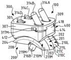
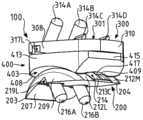
图1和图2以不同的透视图示出了根据本发明的假体的优选实施例,其中除了距骨部件之外,假体还包括胫骨部件和中间部件;Figures 1 and 2 show a preferred embodiment of a prosthesis according to the invention in different perspective views, wherein in addition to the talar component, the prosthesis also comprises a tibial component and an intermediate component;
图3至图5以内侧视图示出了图1和图2的假体根据患者的左脚和胫骨的相对取向(即,分别处于跖屈位置(图3)、所谓的中立位置(图4)和背屈位置(图5))可能采用的三种空间构造;Figures 3 to 5 show in medial views the prosthesis of Figures 1 and 2 according to the relative orientation of the patient's left foot and tibia (i.e. in the plantarflexed position (Figure 3), the so-called neutral position (Figure 4 ) and the dorsiflexion position (Fig. 5)) may adopt three spatial configurations;
图6和图7分别根据顶部和底部透视图示出了图1和图2的假体的距骨部件;Figures 6 and 7 show the talar component of the prosthesis of Figures 1 and 2 according to top and bottom perspective views, respectively;
图8和图9分别以俯视图和仰视图示出了图6和图7的距骨部件;Figures 8 and 9 show the talar component of Figures 6 and 7 in top and bottom views, respectively;
图10根据前后截面图示出了图6至图9的距骨部件;Figure 10 shows the talar component of Figures 6-9 according to anteroposterior cross-sectional views;
图11和图12分别根据顶部和底部透视图示出了图1和图2的假体的胫骨部件;Figures 11 and 12 show the tibial component of the prosthesis of Figures 1 and 2 according to top and bottom perspective views, respectively;
图13和图14分别以俯视图和仰视图示出了图11和图12的胫骨部件;Figures 13 and 14 show the tibial component of Figures 11 and 12 in top and bottom views, respectively;
图15根据前后截面图示出了图11至图14的胫骨部件;Fig. 15 shows the tibial component of Figs. 11-14 according to anterior-posterior cross-sectional views;
图16和图17分别根据顶部和底部透视图示出了图1和图2的假体的中间部件;Figures 16 and 17 show the middle part of the prosthesis of Figures 1 and 2 according to top and bottom perspective views, respectively;
图18和图19分别以俯视图和仰视图示出了图16和图17的中间部件。Figures 18 and 19 show the middle part of Figures 16 and 17 in top and bottom views, respectively.
具体实施方式Detailed ways
本发明涉及踝假体100,包括在图1和图2中示出的优选实施例。所述假体100构成在外科手术上可植入在人类或动物患者的身体中的装置,其用于替换特定的踝关节。有利地,所述假体100被设计成完全替换相关的踝关节(完全的踝假体,TAP)。因此,根据本发明的假体100设计成插入并介于患者的脚的胫骨的下端与对应的距骨之间。有利地,在将根据本发明的假体100装配在患者的身体中之前,所考虑的胫骨和距骨将会经历充分的制备,例如提取软骨元件和骨部段,以便移除待替换的踝关节的自然的关节表面的全部或一部分。The present invention relates to an
在图1至图5中示出为一示例的假体100用于被装配在患者的左脚的高度处。当然,本发明还覆盖了用于被装配在患者的右脚的高度处的假体。有利地,所述假体相对于患者的矢状面由在图中示出的假体100对称地限定。The
根据本发明,所述假体100包括距骨部件200,其包括在图6至图10中示出的优选实施例,并且有利地用于与患者的脚的距骨相关。距骨部件200包括距骨上面201,其限定假体100的第一关节表面202。如图所示,所述距骨上面201沿第一平均方向A-A’在距骨前边缘203与相对的距骨后边缘204之间延伸,并且优选地根据与所述第一平均方向A-A’正交的第二平均方向B-B’在距骨外侧边缘205与相对的距骨内侧边缘206之间延伸。有利地,所述第一平均方向A-A’可以在假体100的正常使用中对应于第一平均前后方向。所述第二平均方向B-B’则可以有利地对应于第一平均外侧-内侧方向。有利地,所述距骨外侧边缘205和所述距骨内侧边缘206是圆形的、带倒角的。According to the invention, said
这里应该指出的是,术语“后”、“前”、“内侧”和“外侧”优选地在本说明书中使用,以在假体100的正常使用中相对于患者身体的限定与它们的相应取向相关联的元件或特征。因此,术语“内侧”优选地用于指代假体100的用于在最接近患者的身体的中间矢状轴线(或中轴线)的一侧(换言之,朝向患者的脚和腿的内侧取向的一侧)上定位和取向的元件。相比之下,术语“外侧”与最远离中间矢状轴线的一侧关联使用。遵循相同的逻辑,术语“后”和“前”优选地指代相对于患者的额状面定位的后方和相应的前方。It should be noted here that the terms "posterior", "anterior", "medial" and "lateral" are preferably used in this specification to define their respective orientations relative to the patient's body in normal use of the
根据图中所示的优选实施例,距骨部件200还包括与所述距骨上面201相对的距骨下面207,并且该距骨下面207有利地在所述距骨前边缘203和距骨后边缘204的高度处连接到距骨上面201。所述距骨下面207优选地被定位成与特别预先制备的患者的距骨的区接触或被定位在特别预先制备的患者的距骨的区上。优选地,距骨下面207由第一和第二大致平坦的连续部分(图7)限定,该第一和第二大致平坦的连续部分大体上根据相应的正割平面、例如以第一平坦部分相对于第二平坦部分30°的仰角延伸。第一平坦部分优选地形成距骨下面207的前部,而在根据本发明的假体100的正常使用中根据大致水平面延伸的第二平坦部分有利地形成距骨下面207的中部和后部。圆角可以设置在所述第一平坦部分和第二平坦部分的连接处。距骨下面207的这种特别简单的设计限制了所需用于先前制备距骨的骨部段(在该情况下为两个)的数量和复杂性,并且有助于将距骨部件200装配在患者身体中。According to the preferred embodiment shown in the figures, the
如图所示,距骨部件200还可以包括距骨内侧面208和相对的距骨外侧面209,它们分别将距骨内侧边缘206和距骨外侧边缘205连接到所述距骨下面207。优选地,所述距骨内侧面208和距骨外侧面209总体上从距骨部件200向外凸出,以便在距骨部件200用于被装配的高度处最佳地遵循距骨的区的自然解剖构造。As shown, the
优选地,根据本发明的假体100包括用于与患者的胫骨的下端相关联的胫骨部件300(图11至图15)。所述胫骨部件300包括胫骨上面301和相对的胫骨下面302。如图所示,所述胫骨下面302优选地一方面优选地根据第三平均方向C-C’在胫骨前边缘303与相对的胫骨后边缘304之间延伸,并且另一方面优选地根据与所述第三平均方向C-C’正交的第四平均方向D-D’在胫骨外侧边缘305和相对的胫骨内侧边缘306之间延伸。Preferably, the
有利地,所述第三平均方向C-C’可以对应于在假体100的正常使用中的第二平均前后方向。所述第四平均方向D-D’然后可以有利地对应于第二平均外侧-内侧方向。在假体100的正常使用中,胫骨部件300的所述第二平均前后方向和第二平均外侧-内侧方向分别有利地平行于距骨部件200的所述第一平均前后方向和第一平均外侧-内侧方向。Advantageously, said third mean direction C-C' may correspond to the second mean anteroposterior direction in normal use of the
在附图所示的优选实施例中,胫骨上面301和胫骨下面302分别根据大致平行的平均延伸平面延伸,所述胫骨部件300为板的通用形式。优选地,所述胫骨上面301定位成与特别预先制备的胫骨的区接触或者定位在特别预先制备的胫骨的区上。如图所示,胫骨部件300还可以包括胫骨内侧面307和相对的胫骨外侧面308,它们分别将胫骨内侧边缘306和胫骨外侧边缘305连接到所述胫骨上面301。有利地,所述胫骨内侧边缘306大致是直线的,并且所述胫骨内侧面307大致是平坦的(图11至图14),使得外科医生可以通过使所述胫骨内侧面307沿在内踝的高度处制成的直线部段对准而将所述胫骨部件300准确地定位在患者的身体中。这有利地允许减少未覆盖的骨部段的面积,这可以促进淋巴腔或囊肿的出现。此外,胫骨部件300可以包括胫骨前面309和相对的胫骨后面310,它们继而分别将胫骨前边缘303和胫骨后边缘304连接到所述胫骨上面301。In the preferred embodiment shown in the figures, the tibial superior 301 and tibial inferior 302 respectively extend according to substantially parallel planes of mean extension, said
优选地,所述距骨部件200和/或所述胫骨部件300相应地形成由生物相容性和耐磨材料制成的一件式零件。有利地,所述距骨部件200和/或所述胫骨部件300由金属材料制成,例如由铬-钴合金CrCo、不锈钢或钛制成。根据变型,所述距骨部件200和所述胫骨部件300相应地由铸造零件构成。根据替代的变型,所述距骨部件200和所述胫骨部件300相应地由机加工零件构成。当然,可考虑其它合适的材料,比如例如陶瓷材料,以及其它制造工艺(通过注射、模制、烧结等)。Preferably, the
有利地,距骨部件200的距骨下面207和/或胫骨部件300的胫骨上面301可以设置有特定的表面涂层(例如由多孔钛或羟基磷灰石制成),或者可以经受特定的机械加工处理(研磨、开槽等),以便促进距骨部件200至距骨的骨钩接和/或胫骨部件300至对应胫骨的骨钩接。Advantageously, the
优选地,根据本发明的假体100还包括中间部件400(或衬垫或插入件)(图16至图19),其被设计成介于所述距骨部件200与所述胫骨部件300之间,如图1至图5中的示例所示。Preferably, the
所述中间部件400包括中间上面401和相对的中间下面402,中间上面401优选地用于与胫骨部件300的胫骨下面302接触,继而中间下面402优选地用于与距骨部件200的距骨上面201接触。所述中间下面402有利地限定假体100的第二关节表面403,其被设计成与由距骨部件200的距骨上面201限定的所述第一关节表面202配合。Said
优选地,所述中间上面401一方面(例如,根据第五平均方向E-E’)在第一中间前边缘404与第一相对的中间后边缘405之间延伸,并且另一方面,(例如,根据与所述第五平均方向E-E’正交的第六平均方向F-F’)在第一中间外侧边缘406与第一相对的中间内侧边缘407之间延伸。所述中间下面402继而优选地一方面根据所述第五平均方向E-E’在第二中间前边缘408与相对的第二中间后边缘409之间延伸,并且另一方面优选地根据所述第六平均方向F-F′在第二中间外侧边缘410和相对的第二中间内侧边缘411之间延伸。如图所示,所述第二中间前边缘408和所述第二中间后边缘409可有利地形成倒角,以便在假体100使用时限制对周围软组织的刺激或损伤的风险。Preferably, said intermediate
中间部件400还可以包括中间内侧面412和相对的中间外侧面413,它们分别将第一中间内侧边缘407和第一中间外侧边缘406连接到所述中间下面402。有利地,由于与上文中结合胫骨部件300的胫骨内侧面307所阐述的原因基本上相同的原因,中间内侧面412基本上是平坦的,而中间外侧面413可以总体上凸出,具有朝向所述中间内侧面412取向的凹面。此外,中间部件400可以包括中间前面414和相对的中间后面415,它们继而分别将第一中间前边缘404和第一中间后边缘405连接到所述中间下面402。The
如图3至图5中所示,中间部件400可以沿平均前后方向通过在距骨部件200上滑动接触而移位,并且具体地,沿大体后-前路径(也就是说,从后部到前部)在距骨后边缘204(跖屈,图3)与距骨前边缘203(背屈,图5)之间移位,从而根据患者的脚相对于患者的胫骨的倾斜度穿过所谓的中立中间位置(图4)。As shown in FIGS. 3 to 5 , the
优选地,所述中间部件400是由具有低摩擦系数的材料(例如,比如高密度聚乙烯(HDPE)的塑料材料)制成的一件式零件。例如,其可以由机加工或模制零件构成。Preferably, said
替代地,假体100可以不包括中间部件400,然后胫骨下面302可以设计成自行限定第二关节表面,该第二关节表面用于与由距骨部件200的距骨上面201限定的第一关节表面202直接配合。Alternatively, the
根据本发明,并且特别如图6中所示,所述第一关节表面202沿所述第一平均方向A-A’是弯曲的、凸出的。相反地,由距骨部件400的中间下面402限定的第二关节表面403优选地沿所述第五平均方向E-E’是弯曲的。所述第一关节表面202优选地大体上是凸形的(也就是说,具有朝向距骨部件200的距骨下面207取向的凹面),而第二关节表面403大体上是凹形的。根据一替代变型(未示出),在不背离本发明的范围的情况下,可以考虑一种相反的构造,即第一关节表面202大体上是凹形的,而第二关节表面403大体上是凸形的。According to the invention, and as shown in particular in Fig. 6, said first
有利地,所述第一关节表面202(并且优选地,所述第二关节表面403)具有源自虚构的锥体的(每个)大致截头圆锥形(虚构的)表面部分的大体平均形状,其表面优选地定向成使得其大的基部朝向外踝取向并且其小的基部朝向被考虑的脚的内踝取向。因此,当中间部件400通过所述第一关节表面202和第二关节表面403的配合相对于距骨部件200以摩擦接触方式移位时,中间部件400不描述严格的前后或后前轨迹,而是相反地描述或多或少的弯曲轨迹。因此,患者的脚有利地在背屈(dorsal flexion)中在外侧(内侧-外侧方向)上被引导,并且相反地在跖屈(plantar flexion)中在内侧(外侧-内侧方向)上被引导。因此,最佳地再现踝的关节的自然生理运动。Advantageously, said first articular surface 202 (and preferably said second articular surface 403) has a generally average shape derived from (each) generally frusto-conical (imaginary) surface portion of an imaginary cone , its surface is preferably oriented such that its large base is oriented towards the lateral malleolus and its small base is oriented towards the medial malleolus of the foot under consideration. Therefore, when the
替代地,所述第一关节表面202和第二关节表面403每个都可以具有圆柱形(虚构的)表面部分的平均大体形状,以便相反地限定关节运动,其中中间部件400沿大致前后或后前轨迹移位。Alternatively, the first articulating
根据本发明,所述第一关节表面202包括至少两个不同的曲面部分,即至少一个第一弯曲部分202A和一个第二弯曲部分202B,每一个沿第一平均方向A-A’延伸,并且沿所述第一平均方向A-A’彼此前后对准,沿所述第一平均方向A-A’,所述第一弯曲部分202A具有第一曲率,并且所述第二弯曲部分202B具有第二曲率。According to the invention, said first
因此,当观察沿平行于所述第一平均方向A-A’且正交于所述第二平均方向B-B’的平面中的截面时(图10),所述第一关节表面202由至少两个不同的曲线部分(在图10中分别由关于对应的第一和第二弯曲部分的相同附图标记202A和202B表示)描述,优选地,每个形成弧形,其凹面优选地指向距骨下面207,所述曲线部分具有彼此不同的(可能平均的)曲率中心。Thus, when viewing a section in a plane parallel to the first mean direction AA' and normal to the second mean direction BB' ( FIG. 10 ), the first
根据一优选变型,第一关节表面202的第一弯曲部分202A和第二弯曲部分202B分别大体上类似于第一和第二大体截头圆锥形(虚构的)表面部分,所述第一表面部分和第二表面部分优选地分别源自具有相应的第一旋转轴线和第二旋转轴线的第一虚拟虚构椎体和第二虚拟虚构锥体。有利地,所述第一虚构椎体和第二虚构锥体中的每个的顶点处的半角的值为8°。该特定构造的选择有助于最佳地再现解剖踝的自然运动。According to a preferred variant, the first
替代地,第一关节表面202的所述第一弯曲部分202a和第二弯曲部分202b可以分别大体类似于第一和第二大致圆柱形表面部分,所述第一和第二表面部分优选地分别源自具有相应的第一和第二旋转轴线的第一和第二虚构圆柱体。Alternatively, the first curved portion 202a and the second curved portion 202b of the first
换言之,如果所述第一关节表面202如前所述具有虚构的(或圆柱形)锥体的大致截头圆锥形(虚构的)表面部分的平均大体形状,则在本发明的含义内,该平均大体形状通过大致截头圆锥形(或圆柱形)表面的至少第一和第二不同部分的组合被更具体地限定。这些大致截头圆锥形表面中的每个优选地取向成使得其大的基部朝向外踝取向,并且其小的基部朝向所考虑脚的内踝取向。因此,对应于第一弯曲部分202A的第一截头圆锥形表面部分具有沿所述第二平均方向B-B’的外侧-内侧方向变化并且在大曲率半径R1与小曲率半径r1之间逐渐减少的曲率半径。对应于第二弯曲部分202B的第二截头圆锥形表面部分继而具有沿所述第二平均方向B-B’的外侧-内侧方向变化、在大曲率半径R2与小曲率半径r2之间逐渐减少的曲率半径。In other words, if said first
替代地,在所述第一弯曲部分202A和第二弯曲部分202B大体上类似于第一和第二大致圆柱形表面部分的情况下,所述第一和第二大致圆柱形表面部分可以分别具有沿所述第二平均方向B-B’为恒定的曲率半径R'1、R'2。Alternatively, where the first
根据本发明,所述第一曲率和所述第二曲率是不同的,由此使得所述第一弯曲部分202A和第二弯曲部分202B中的一个更弯曲,也就是说,比另一个更显著地弯曲。According to the invention, said first curvature and said second curvature are different such that one of said first
根据上文所考虑的优选实施例,其中第一关节表面202的第一弯曲部分202A和第二弯曲部分202B分别大体上类似于第一和第二大致截头圆锥形(虚构的)表面部分,这种曲率上的差异可能导致:第一截头圆锥形表面部分具有分别不同于相应的第二截头圆锥形表面部分的大曲率半径R2和小曲率半径r2的大曲率半径R1和小曲率半径r1(R1≠R2和r1≠r2)。根据其中所述第一弯曲部分202A和第二弯曲部分202B分别大体上类似于第一和第二大致圆柱形表面部分的替代变型,这种曲率上的差异可以导致:第一圆柱形表面部分具有与第二圆柱形表面部分的相应曲率半径R'2不同的曲率半径R'1。According to the preferred embodiment considered above, wherein the first
因此,由距骨上面201限定的第一关节表面202有利地不具有截头圆锥形(或圆柱形,如上文考虑的替代地)表面部分的精确和完美的形状,而且相反,其沿所述第一平均方向A-A’包括其平均总体曲率的特定局部变型。假体100的一般运动随后不由单个旋转限定,而是通过对应于脚相对于胫骨的至少两个空间构造、以不同半径的至少两个旋转来限定。因此,可以通过假体关节在跖屈位置与背屈位置之间的不同旋转轴线来生成复杂的关节移动,并且甚至更可靠地达到解剖踝的自然运动行为。Thus, the first
在图中所示的优选实施例中,所述第一弯曲部分202A和所述第二弯曲部分202B分别限定(或至少部分地限定)所述第一关节表面202的前部和后部。因此,所述第一弯曲部分202A优选地在距骨部件200的距骨上面201的距骨前边缘203和距骨后边缘204之间延伸,并且更优选地从所述距骨前边缘203(或至少从距骨前边缘203的紧邻区域)朝向所述距骨后边缘204延伸。所述第二弯曲部分202B然后相应地在所述第一弯曲部分202A与所述距骨后边缘204之间延伸。仍优选地,所述第二弯曲部分202B与所述第一弯曲部分202A邻接,并且使后者延伸至所述距骨后边缘204(或至少延伸至后者的紧邻区域)。第一弯曲部分202A和第二弯曲部分202B由此沿第一平均方向A-A’前后对准,第一弯曲部分202A(前部)定位在第二弯曲部分202B(后部)前方。因此,当沿平行于第一平均方向A-A’且正交于第二平均方向B-B’的平面观察截面时(图10),所述第一关节表面202由至少两个不同的、优选为对接的曲线部分表征,每个优选地形成弧形,并且优选地将距骨前边缘203连接至距骨后边缘204。In the preferred embodiment shown in the figures, the first
然后,所述第一弯曲部分202A有利地对应于第一关节表面202的一部分,其中,中间部件400的第二关节表面403在患者的脚的背屈构造中与第一关节表面202的该部分配合(图5),而所述第二弯曲部分202对应于第一关节表面202的另一部分,其中,中间部件400的所述第二关节表面403在患者的脚的跖屈构造中与第一关节表面202的该另一部分配合(图3)。Said first
有利地,所述第一曲率和第二曲率以及所述第一旋转轴线和第二旋转轴线的相对定位被选择为以确保所述第一关节表面202的所述第一弯曲部分202A和第二弯曲部分202B之间的规则的且协调的过渡。Advantageously, the relative positioning of the first and second curvatures and the first and second axes of rotation is selected to ensure that the first
优选地,所述第一大致截头圆锥形表面部分和第二大致截头圆锥形表面部分在接触平面中接合在一起,所述接触平面相对于包含所述第二旋转轴线的竖直平面朝向所述距骨前边缘203以包括在10°与30°之间的角度、优选地以大约20°的角度倾斜,所述接触平面包含所述第一旋转轴线和第二旋转轴线。实际上,已经观察到,由此获得了所施加的假体的角位移的增加和固有稳定性之间的极好折衷。Preferably, said first and second generally frustoconical surface portions are joined together in a contact plane oriented relative to a vertical plane containing said second axis of rotation. The
优选地,第一弯曲部分202A的所述第一曲率大于第二弯曲部分202B的所述第二曲率,也就是说,第一关节表面202的所述第一弯曲部分202A在第一平均方向A-A’上生成比第一关节表面202的所述第二弯曲部分202B的相应曲率更大的曲率(R1<R2和r1<r2,或R'1<R'2)。Preferably, the first curvature of the first
在所述第一弯曲部分202A和第二弯曲部分202B分别限定第一关节表面202的前部和后部的前述优选情况下,所述第一关节表面202因此有利地在其前部比在其后部具有更显著的曲率。这种构造是特别令人感兴趣的,因为它能够允许以更大的角位移来使患者进行背屈,而无需使患者的距骨在前后方向上(即,向后)偏移。通过装备根据本发明的假体100,患者因此例如在步行阶段(其中脚在跨步结束时离开地面)期间,或者当他设法攀爬楼梯的台阶时可以更容易地屈曲他的脚。In the aforementioned preferred case where the first
优选地,所述第一曲率(沿第一平均方向A-A′)是恒定的或可变的,而所述第二曲率(沿第一平均方向A-A′)是恒定的。这种第一可变曲率可以有利地对应于一特定实施例,根据所述特定实施例,第一弯曲部分202A的大体形式进而大体上由大致截头圆锥形或圆柱形(并且不仅由前述第一部分)的多个n个不同表面部分的组合限定,各部分具有不同的小的rn和大的Rn曲率半径(或半径R′n)(并且因此具有不同的第n曲率),其有利地沿所述第一平均方向A-A’逐渐减小。Preferably, said first curvature (along first mean direction A-A') is constant or variable and said second curvature (along first mean direction A-A') is constant. This first variable curvature may advantageously correspond to a specific embodiment according to which the general form of the first
在其中第一弯曲部分202A限定第一关节表面202的前部并且其中所述第n曲率朝向胫骨前边缘203逐渐变化的优选情况下,这种第一可变曲率的实施方式有利地允许进一步改善由处于背屈中的假体100提供的角位移的幅度。In the preferred case where the first
可能施加在第一关节表面202和第二关节表面403的界面处的关节内力在跖屈阶段比在背屈阶段中更显著,所述第二弯曲部分202B优选地设计和定尺寸为使得其有利地具有大于所述第一弯曲部分202A的相应表面面积的表面面积。由此确保在跖屈中更好地恢复关节内力,这允许改善假体100的稳定性以及使用寿命。Intra-articular forces that may be exerted at the interface of the first
优选地,第一关节表面202形成假体双髁表面,并且包括:Preferably, the first
-距骨外侧区210L,其沿所述第一平均方向A-A’在所述距骨前边缘203与所述距骨后边缘204之间延伸,并且沿所述第二平均方向B-B’在所述距骨外侧边缘205与所述距骨内侧边缘206之间延伸;以及- the lateral region of the
-距骨内侧区210M,其沿所述第一平均方向A-A’在所述距骨前边缘203与所述距骨后边缘204之间延伸,并且沿所述第二平均方向B-B’在所述距骨外侧区210L与所述距骨内侧边缘206之间延伸。- Talar
仍优选地,如特别在图6和图8中所示,所述距骨外侧区210L和距骨内侧区210M分别从所述距骨前边缘203(或至少从所述距骨前边缘203的紧邻区域)延伸至所述距骨后边缘204(或至少从所述距骨后边缘204的紧邻区域)。然后,所述距骨外侧区210L包括所述第一弯曲部分202A的第一外侧区域211L和所述第二弯曲部分202B的第二外侧区域212L。所述距骨内侧区210M分别包括所述第一弯曲部分202A的第一内侧区域211M和所述第二弯曲部分202B的第二内侧区域212M。如图所示,第二外侧区域212L和第二内侧区域212M然后优选地沿第一平均方向A-A’分别延伸第一外侧区域211L和第一内侧区域211L。有利地,所述距骨外侧区210L和距骨内侧区210M因此沿第一平均方向A-A’分别形成连续的外侧和内侧假体髁部。Still preferably, as shown particularly in FIGS. 6 and 8 , said
有利地,所述第一关节表面202还包括距骨中央区210C,其介于所述距骨外侧区210L与所述距骨内侧区210M之间。如图所示,所述距骨中央区210C沿所述第一平均方向A-A’从所述距骨前边缘203(或至少从所述距骨前边缘203的紧邻区域)朝向距骨后边缘204延伸,并且有利地包括所述第一弯曲部分202A的第一中央区域211C。Advantageously, the first
以特别有利的方式,所述距骨中央区211C还包括第二弯曲中央区域213C,其朝向距骨后边缘204延伸所述第一中央区域211C。然而,所述第二中央区域213C因此优选地不构成第二弯曲部分202B的中央区域。实际上,所述第二中央区域213C沿第一平均方向A-A’有利地具有第三曲率,该第三曲率不同于第二弯曲部分202B的第二曲率。所述第二弯曲部分202B然后沿第二平均方向B-B’是不连续的。在该情况下,并且特别是根据图中所示的优选实施例,其中第一弯曲部分202A的第一曲率大于第二弯曲部分202B的第二曲率,第二中央区域213C的所述第三曲率有利地大于所述第二曲率。因此,第二中央区域213C因此比周围的第二外侧区域212L和第二内侧区域212M更显著地弯曲。例如,所述第三曲率可以等同于所述第一曲率,第二中央区域213C与第一中央区域211C连续地放置。In a particularly advantageous manner, said talar
如特别在图6和图8中所示,所述第二中央区域213C然后有利地实现在所述第一关节表面202的平均包络面(envelope)中的后中央凹部214。此外,第一关节表面202的所述距骨中央区210C可以不延伸到距骨上表面201的距骨后边缘204。因此,形成在所述距骨中央区210C与所述距骨后边缘204之间的空间可以是空的,或者相反,优选地由实体的互补部分215和例如平坦的距骨上面201填充,从而避免形成未覆盖的骨部段区。As shown in particular in FIGS. 6 and 8 , said second
根据图中所示的优选实施例,由中间部件400的中间下面402限定的所述第二关节表面403有利地包括中间外侧区416L、中间内侧区416M,并且还优选地包括中间中央区416C,中间中央区416C介于两个前述区之间。According to the preferred embodiment shown in the figures, said second
所述中间外侧区416L、中间内侧区416M和中间内侧区416C每个都沿所述第五平均方向E-E’在所述第二中间前边缘408与第二中间后边缘409之间延伸,所述中间外侧区416L、中间内侧区416M和中间内侧区416C分别用于与所述第一关节表面202的所述距骨外侧区210L、距骨内侧区210M和距骨中央区210C配合。优选地,所述中间外侧区416L和中间内侧区416M沿所述第五平均方向E-E’有利地具有分别与所述第一关节表面202的第二弯曲部分202B的所述第二外侧区域212L和第二内侧区域212M的曲率匹配的曲率。所述中间中央区416C进而有利地沿所述第五平均方向E-E’具有与所述第一关节表面202的第一弯曲部分202A的所述第一中央区域211C的曲率匹配的曲率。said intermediate
优选地,并且特别如图6至图8中所示,所述距骨中央区210C沿所述第二平均方向B-B’具有凸曲率,所述距骨外侧区210L和距骨内侧区210M沿所述第二平均方向B-B’分别具有凹曲率。相反地,中间外侧区416L和中间内侧区416M沿所述第六平均方向F-F’有利地是凸起的,而中间中央区416C沿该相同方向F-F’是凹入的(图17)。Preferably, and as shown in particular in FIGS. The second mean direction BB' respectively has a concave curvature. Conversely, the intermediate
因此,在患者的脚的跖屈位置(图3)中,所述中间外侧区416L和中间内侧区416M可以有利地分别与第一关节表面202的第二弯曲部分202B的所述第二外侧区域212L和第二内侧区域212M以表面接触的方式安置。Thus, in the plantarflexed position of the patient's foot ( FIG. 3 ), the medial
在背屈位置(图5)中,所述中间中央区416C可以有利地与第一关节表面202的第一弯曲部分202A的第一中央区域211C表面接触地安置。然而,由于它们各自不同的曲率,所述中间外侧区416L和中间内侧区416M然后可以优选地不与第一关节表面202的第一弯曲部分202A的第一外侧区域211L和第一内侧区域211M以表面接触的方式安置。In the dorsiflexed position ( FIG. 5 ), the intermediate
因此,所述第一关节表面和第二关节表面的配合有利地并不是一致的。在背屈位置中,中间部件400以外侧或以内侧方式围绕平衡位置有利地保持自由地略微滑动和倾斜。在外侧倾斜的情况下,第二关节表面403的中间外侧区416L可以有利地抵靠由距骨部件200的距骨上面201限定的第一关节表面202的第一弯曲部分202A的第一外侧区域211L形成线性接触。相反地,在内侧倾斜的情况下,所述第二关节表面403的中间内侧区416M可以有利地抵靠第一关节表面202的第一弯曲部分202A的第一内侧区域211M形成线性接触。此外,在背屈位置中,中间部件400然后有利地具有围绕竖直轴线的一些有限的旋转自由度。Thus, the fit of the first articular surface and the second articular surface is advantageously not uniform. In the dorsiflexed position, the
因此,通过允许中间部件400保持沿内侧-外侧方向的平移和沿竖直轴线的旋转的轻微可动性,在假体100的正常使用中,这种构造在施加在假体100上的机械应力的作用下有利地有助于限制距骨部件200和胫骨部件300松开的风险。此外,这种构造有利地允许在一定程度上补偿距骨部件200和胫骨部件300的轻微的相对定位缺陷,这有助于促进由外科医生在患者身体中装配假体100。Thus, by allowing
由于根据前述的中间中央区416C优选地具有大于中间外侧区416L和中间内侧区416M的相应曲率的曲率,因此其然后可以在第二中间后边缘409附近限定从中间下面402的表面突出的突出部417(图17)。为了避免所述突出部417与第一关节表面202之间的任何机械相互作用,(如上所述,由距骨中央区210C的第二中央区域213C实现)所述后中央凹部214有利地是空的。因此,在跖屈位置中,所述突出部417可以有利地在所述后中央凹部214中渐隐。Since the intermediate
根据变型(图中未示出),所述胫骨部件300设计成可相对于所述中间部件400移动,所述胫骨部件300和中间部件400然后优选地不机械互连。在这种情况下,所述胫骨下面302和所述中间上面401优选地大致是平坦的和光滑的,使得胫骨部件300和中间部件400可以彼此抵靠形成平坦的表面接触。在假体100的正常使用中,胫骨部件300和中间部件400因此彼此抵靠接触,并且沿三个自由度(即,根据沿前后平均方向的平移、沿内侧-外侧平均方向的平移,以及围绕与所述胫骨下面302和中间上面401其间的接触平面正交的轴线的旋转)能够相对于彼此移动。According to a variant (not shown in the figures), said
根据图1至图5中所示的另一变型,所述胫骨部件300设计成被紧固、即被固定到所述中间部件400,以有利地抑制胫骨部件300与中间部件400之间的任何自由度。胫骨部件300的这种固定有利地允许改善假体关节的稳定性。优选地,所述胫骨部件300和中间部件400设计成使用(更优选地根据燕尾形组件的)相应的第一和第二互补固定元件彼此紧固。According to another variant shown in FIGS. 1 to 5 , said
根据图中所示的优选实施例,胫骨部件300的胫骨下面302因此有利地设置有、例如具有梯形截面的凹槽311,其有利地形成所述第一固定元件(或燕尾形凹状构件)。相反地,中间部件400的中间上面401有利地设置有柱418,柱418形成所述第二固定元件(或燕尾形凸状构件)。如图16和图18中所示,所述柱418从所述中间上面401的表面突出,并且具有与所述凹槽311的形状和尺寸互补的形状和尺寸。According to the preferred embodiment shown in the figures, the
优选地,所述凹槽311沿所述第三平均方向C-C’在其敞开的高度处从胫骨部件300的胫骨前面309朝向胫骨后面310纵向延伸,并且在至少超过分隔开所述胫骨前面309和胫骨后面310(图12和图14)的平均距离的一半上延伸。有利地,所述柱418沿所述第五平均方向E-E’从中间部件400的中间前面414朝向中间部件400的中间后面415纵向延伸。优选地,所述柱418的长度小于所述凹槽311的相应长度(图16和图18)。Preferably, said
因此,所述凹槽311被有利地设计和构造成以窄的滑动方式接收所述柱418,所述胫骨下面302和中间上面401然后被保持为彼此压靠。因此,这种相对的燕尾形组件有利地允许阻挡中间部件400相对于胫骨部件300的至少任何内侧外侧平移和任何旋转。有利地,所述柱418可以在其后端处设置有外侧斜坡419A、419B(或倒角),所述外侧斜坡419A、419B(或倒角)设计成在胫骨部件300和中间部件400的相对组装期间促进和引导柱418在凹槽311中的引入。Thus, said
当然,可以考虑相反的构造,所述胫骨下面302设置有所述柱,所述中间上面401相反地设置有凹槽。也可以实施用于相互紧固、实施不同于上文所述那些的第一和第二固定机构的任何其它合适的机构。Of course, the opposite configuration can be considered, the tibial
此外,可以有利地提供不同大小的胫骨部件300和中间部件400,所述凹槽311和所述柱418的尺寸相应的是相同的。然后,在确保对应于不同大小的假体的胫骨部件300和中间部件400之间的兼容性的同时,有利地可以向外科医生提议一种假体套件,该假体套件包括一套分别具有适于待治疗的患者的形态的不同大小的距骨部件200、胫骨部件300和中间部件400。Furthermore, different sizes of
在这种燕尾形组件的优选情况下,所述胫骨部件300和中间部件400优选地进一步包括设计为限制或阻挡中间部件400相对于胫骨部件300的前后平移(即,从前部到后部)的相应互补的第一止挡元件和第二止挡元件,所述第一和第二止挡元件有利地不同于所述第一和第二互补固定元件。换言之,前后平移的限制(并且优选地阻挡)有利地不由燕尾形组件自身确保(或至少不排他地),而是通过所述第一和第二互补止挡元件的配合来确保。因此,当使用假体100时,这有利地避免了仅通过凹槽311和柱418施加到胫骨部件300的机械作用力的恢复。In the preferred case of such a dovetail-shaped assembly, the
优选地,所述第一止挡元件和第二止挡元件分别包括至少定位在胫骨部件300的胫骨下面302的胫骨后边缘304的高度处的凸缘312,以及形成在中间部件400的中间上面401的高度处(例如,在第一中间后边缘405的高度处)且具有与所述凸缘312的轮廓互补的轮廓的间隙420。因此,所述间隙420被设计和构造成接收所述凸缘312,所述胫骨下面302和中间上面401有利地抵靠彼此平坦接触。因此,凸缘312和间隙420的配合限制了并且优选地阻挡了柱418在凹槽311中的前后行进。当然,可以实施具有不同设计的止挡元件。Preferably, said first and second stop elements respectively comprise a
根据图中所示的优选实施例,所述凸缘312定位在胫骨部件300的胫骨下面302的所述胫骨后边缘304、胫骨外侧边缘305和胫骨内侧边缘306的高度处,并且有利地沿所考虑的边缘304、305、306以基本上连续的方式延伸。所述凸缘312优选地具有矩形截面,其可以是恒定的或非恒定的。相反地,所述间隙420优选地形成在所述中间部件400的中间上面401的第一中间后边缘405、第一中间外侧边缘406和第一中间内侧边缘407的高度处,有利地沿所考虑的边缘405、406、407以基本连续的方式延伸。According to the preferred embodiment shown in the figures, said
因此,这种有利的半周边互补的凸缘312和间隙420的实施方式以及在中间部件400紧固到胫骨部件300时的它们的配合,不仅允许限制柱418在所述凹槽311中剪切的风险,而且还有利地在假体100的正常使用中通过在由胫骨部件300施加在中间部件400上的压缩力的作用下的蠕变(creeping)而使中间部件400变形的风险。因此,显著改善了中间部件400的使用寿命,这允许限制必须继续进行后续手术操作以替换中间部件400的风险。Thus, this advantageous semi-peripheral
优选地,为了同样阻挡中间部件400相对于胫骨部件300的任何后前部平移(即,从后部到前部),当二者彼此紧固时,所述胫骨部件300和中间部件400有利地分别设置有第一313A、313B和第二421A、421B互补锁定机构。Preferably, said
如图12和图14中所示,所述第一锁定机构313A、313B例如对称地位于所述胫骨部件300的胫骨外侧边缘305和胫骨内侧边缘306的高度处、例如可以是形成在胫骨下面302的凸缘312中的锯齿状槽口313A、313B的形式。相反地,所述第二锁定机构421A、421B进而可以是例如、布置在中间部件400的间隙420的高度处的突耳421A、421B的形式(图16至图18),突耳421A、421B具有与所述锯齿状槽口313A、313B互补的形状。因此,胫骨部件300和中间部件400可以通过夹持而彼此锁定,形成中间部件400的材料的局部弹性变形允许中间部件400的突耳421A、421B接合在胫骨部件300的对应的槽口313A、313B中。当然,可以考虑其它第一313A、313B和第二421A、421B合适的互补锁定机构,而不是刚刚描述的那些。As shown in FIGS. 12 and 14 , the
优选地,胫骨部件300设计成可移除地紧固到中间部件400,特别是为了在中间部件400(磨损、变形等)退化的情况下允许替换中间部件400。在这种情况下,第一313A、313B和第二421A、421B互补锁定机构被设计成允许胫骨部件300和中间部件400之间的可逆锁定。因此,中间部件400可以例如设置有在形成所述第二锁定机构421A、421B的突耳421A、421B紧邻区域中的中间上面401中形成的并且被设计为接收外部仪器(未示出,例如平头螺丝刀)的端部的凹陷422A、422B。该外部仪器的作用,例如通过杠杆效应或通过旋转,将有利地允许形成中间部件400的材料的局部弹性变形和槽口313A、313B与突耳421A、421B的分离,从而允许距骨部件300和中间部件400的脱开。Preferably, the
有利地,距骨部件200在其距骨下面207的高度处设置有至少一个距骨锚定机构216A,其设计成确保将距骨部件200锚定在相关距骨的骨块中。优选地,所述距骨锚定机构216A从距骨部件200的距骨下面207突出,在将距骨部件200装配在患者身体中期间,所述距骨锚定机构216A有利地旨在被容纳在由外科医生在距骨的骨块中预先(或者在距骨部件200的装配期间)实施的对应的壳体(或孔)中。如图7和图9中特别示出的,距骨部件200设置有两个距骨锚定机构216A、216B,这两个距骨锚定机构由例如是圆柱形的具有圆形头部的两个距骨螺柱216A、216B形成,其从距骨部件200的距骨下面207突出。优选地,所述距骨螺柱216A、216B以倾斜方式朝向距骨后边缘204延伸。当然,可以考虑其它合适类型、形状和构造的距骨锚定机构216。Advantageously, the
为了确保所述距骨锚定机构216A的优异的机械阻力(尤其是疲劳),距骨锚定机构216A优选地在其基部的高度处通过距骨圆角217A(即,通过弯曲表面,或通过一个或多个肋部)连接到距骨下面207。在图中所示的优选实施例中,距骨锚定机构216A、216B中的每个由此通过相应的距骨圆角217A、217B有利地连接到距骨下面207。然而,已经观察到,在(例如通过压紧)将距骨部件200装配到患者身体期间,这种圆角217A、217B的存在可能会产生麻烦,程度达到这种圆角217A、217B则从距骨下面207的表面突出。实际上,通常可用于在骨块中制造壳体的钻头不允许容易地制造可能接收圆角217A、217B的埋头孔。这种圆角217A、217B的实施方式在前面考虑的情况下是尤其不利的,其中距骨下面207设置有表面涂层,因为表面涂层的存在倾向于根据其厚度来增强所述圆角217A、217B的重要性,并且因此进一步阻碍所述距骨部件200的装配。In order to ensure excellent mechanical resistance (especially fatigue) of the
为了克服该缺点,所述距骨下面207有利地设置有至少一个距骨收纳池218A,通过至少一个距骨收纳池218A的底部,所述至少一个距骨锚定机构216A从所述距骨下面207突出。在图中所示的优选实施例中,所述距骨下面207有利地设置有多个距骨收纳池218A、218B,通过多个距骨收纳池218A、218B的相应底部,所述距骨螺柱216A、216B从所述胫骨上面301突出。如图中所示,所述距骨收纳池218A、218B有利地定尺寸为使得所述圆角217A、217B一体地容纳在所述距骨收纳池218A、218B中,并且因此不从距骨下面207的表面突出。In order to overcome this shortcoming, said
因此,所述距骨部件200可以以相对简单和准确的方式装配在距骨的高度处,距骨下面207能够与距骨的对应的区进行完美地表面接触,并且不需要用于钻骨块的特定工具。Thus, the
有利地,胫骨部件300在其胫骨上面301的高度处设置有至少一个胫骨锚定机构314A,其设计成确保将胫骨部件300锚定在相关胫骨的骨块中。优选地,所述胫骨锚定机构314A从胫骨部件300的胫骨上面301突出,在胫骨部件300装配在患者身体中期间,所述胫骨锚定器件314A有利地旨在被容纳在由外科医生在胫骨的骨块中预先(或在胫骨部件300的装配期间)实施的至少一壳体(或孔)中。Advantageously, the
如特别在图11至图13和图15中所示,胫骨部件300优选地设置有多个胫骨锚定机构314A、314B、314C、314D,多个胫骨锚定机构314A、314B、314C、314D例如由具有圆形头部的从胫骨前边缘303附近的所述胫骨上面301突出的两个圆柱形胫骨螺柱314A、314B以及由从胫骨后边缘304附近的所述胫骨上面301突出的两个胫骨翅片314C、314D形成。优选地,所述胫骨翅片314C、314D具有尖锐的及甚至锋利的脊部,以促进它们刺入到胫骨的骨块中。有利地,所述胫骨螺柱314A、314B和所述胫骨翅片314C、314D以倾斜的方式朝向胫骨后边缘304延伸。所述胫骨螺柱314A、314B和所述胫骨翅片314C、314D的倾斜角将有利地选择为便于将胫骨部件400引入到患者身体中,并将其装配在患者的胫骨的高度处,同时限制必要的关节牵引。当然,可以考虑其它合适类型、形状和构造的胫骨锚定机构314A、314B、314C、314D。As shown particularly in FIGS. 11-13 and 15 , the
优选地,以大致类似于上文中描述的结合距骨部件200的所述至少一个距骨锚定机构216A的方式,所述至少一个胫骨锚定机构314A优选地在其基部的高度处通过胫骨圆角315A连接到胫骨上面301。然后,所述胫骨上面301有利地设置有至少一个胫骨收纳池316A,从至少一个胫骨收纳池316A的底部,所述至少一个胫骨紧固机构314A从所述胫骨上面301突出。在图中所示的优选实施例中,胫骨螺柱314A、314B中的每个和胫骨翅片314C、314D中的每个因此有利地通过相应的胫骨圆角315A、315B、315A、315B连接到胫骨上面301。然后,所述胫骨上面301有利地设置有多个胫骨收纳池316A、316B、316A、316B,从多个胫骨收纳池316A、316B、316A、316B的相应底部,所述胫骨螺柱314A、314B和所述胫骨翅片314C、314D从所述胫骨上面301突出。Preferably, the at least one
如图7和图9中所示,距骨部件200的距骨外侧边缘205和距骨内侧边缘206优选地分别设置有距骨外侧槽口219L和距骨内侧槽口219M,距骨外侧槽口219L和距骨内侧槽口219M有利地以对称的方式定位在距骨前边缘203附近。所述距骨外侧槽口219L和所述距骨内侧槽口219M有利地设计成与外部仪器(未示出,例如平头螺丝刀)配合,以允许距骨部件200的消融,例如在不令人满意的定位的情况下,或者在医疗并发症的情况下,证明假体100的全部或部分的移除是合理的。As shown in FIGS. 7 and 9 , the
类似地,胫骨部件300的胫骨外侧边缘305和胫骨内侧边缘306可以有利地分别设置有胫骨外侧槽口317L和胫骨内侧槽口317M,胫骨外侧槽口317L和胫骨内侧槽口317M有利地对称地定位在胫骨前边缘303附近(图11、图12和图14)。Similarly,
Claims (18)
Priority Applications (1)
| Application Number | Priority Date | Filing Date | Title |
|---|---|---|---|
| CN202310775211.1ACN116999219A (en) | 2017-09-05 | 2018-09-05 | ankle prosthesis |
Applications Claiming Priority (2)
| Application Number | Priority Date | Filing Date | Title |
|---|---|---|---|
| FR1758185AFR3070593A1 (en) | 2017-09-05 | 2017-09-05 | PROSTHESIS OF IMPROVED ANKLE |
| FR1758185 | 2017-09-05 |
Related Child Applications (1)
| Application Number | Title | Priority Date | Filing Date |
|---|---|---|---|
| CN202310775211.1ADivisionCN116999219A (en) | 2017-09-05 | 2018-09-05 | ankle prosthesis |
Publications (2)
| Publication Number | Publication Date |
|---|---|
| CN109419574A CN109419574A (en) | 2019-03-05 |
| CN109419574Btrue CN109419574B (en) | 2023-07-14 |
Family
ID=60182749
Family Applications (2)
| Application Number | Title | Priority Date | Filing Date |
|---|---|---|---|
| CN202310775211.1APendingCN116999219A (en) | 2017-09-05 | 2018-09-05 | ankle prosthesis |
| CN201811030372.3AActiveCN109419574B (en) | 2017-09-05 | 2018-09-05 | Improved ankle prosthesis |
Family Applications Before (1)
| Application Number | Title | Priority Date | Filing Date |
|---|---|---|---|
| CN202310775211.1APendingCN116999219A (en) | 2017-09-05 | 2018-09-05 | ankle prosthesis |
Country Status (5)
| Country | Link |
|---|---|
| US (1) | US10952865B2 (en) |
| EP (1) | EP3449876B1 (en) |
| CN (2) | CN116999219A (en) |
| ES (1) | ES2795350T3 (en) |
| FR (2) | FR3070593A1 (en) |
Families Citing this family (19)
| Publication number | Priority date | Publication date | Assignee | Title |
|---|---|---|---|---|
| AU2016388305B2 (en)* | 2015-01-20 | 2019-06-06 | Exactech, Inc. | Talar implant for modifying joint kinematics |
| EP3435926A4 (en)* | 2016-03-28 | 2020-08-05 | Wright Medical Technology, Inc. | ANTERIOR SURFACE REPLACEMENT ALAR PLATE |
| KR102066837B1 (en)* | 2017-08-29 | 2020-01-16 | 주식회사 코렌텍 | Talar component of artificial ankle joint |
| FR3070593A1 (en)* | 2017-09-05 | 2019-03-08 | In2Bones | PROSTHESIS OF IMPROVED ANKLE |
| FR3071400B1 (en)* | 2017-09-28 | 2019-10-04 | Biotechni | ANKLE PROSTHESIS COMPRISING A TALEN IMPLANT, A TIBIAL IMPLANT AND AN INSERT, KIT INCLUDING AT LEAST ONE SUCH PROSTHESIS, AND CUTTING GUIDE FOR THE PLACEMENT OF THE TIBIAL IMPLANT |
| WO2020013901A2 (en) | 2018-04-24 | 2020-01-16 | Paragon 28, Inc. | Implants and methods of use and assembly |
| TWI786139B (en)* | 2018-06-22 | 2022-12-11 | 財團法人工業技術研究院 | Artificial joint |
| CN110013364A (en)* | 2019-04-26 | 2019-07-16 | 中国人民解放军联勤保障部队第九二〇医院 | A bionic fixation-resistant talus replacement part for the upper end of the talus with high conformability |
| CN110013360A (en)* | 2019-04-26 | 2019-07-16 | 中国人民解放军联勤保障部队第九二〇医院 | A high-conformity tibia-talus bionic cooperating joint |
| EP3975939B1 (en) | 2019-05-29 | 2024-11-13 | Wright Medical Technology, Inc. | Device for preparing a tibia for receiving tibial implant component of a replacement ankle |
| US11324601B2 (en)* | 2019-09-30 | 2022-05-10 | Paragon Advanced Technologies, Inc. | Talus implant |
| WO2021146015A1 (en) | 2020-01-17 | 2021-07-22 | Wright Medical Technology, Inc. | Guidance tools, systems, and methods |
| AU2021289599B2 (en)* | 2020-06-10 | 2025-02-20 | Paragon 28, Inc. | Implants and methods of use, assembly and fabrication |
| US12053247B1 (en) | 2020-12-04 | 2024-08-06 | Onpoint Medical, Inc. | System for multi-directional tracking of head mounted displays for real-time augmented reality guidance of surgical procedures |
| WO2022183150A1 (en)* | 2021-02-24 | 2022-09-01 | Wright Medical Technology, Inc. | Implant peg with multiple components |
| US12127946B2 (en) | 2021-04-01 | 2024-10-29 | Wright Medical Technology, Inc. | Low-profile prostheses, systems, and methods |
| CN113797000A (en)* | 2021-10-09 | 2021-12-17 | 北京大学人民医院 | A talus fusion surface type artificial ankle joint prosthesis |
| CN113827378B (en)* | 2021-11-24 | 2022-05-03 | 北京爱康宜诚医疗器材有限公司 | Ankle tibial prosthesis |
| AU2023287753A1 (en)* | 2022-06-22 | 2025-02-06 | Paragon 28, Inc. | Orthopedic implants and instruments |
Citations (1)
| Publication number | Priority date | Publication date | Assignee | Title |
|---|---|---|---|---|
| US8668743B2 (en)* | 2010-11-02 | 2014-03-11 | Adam D. Perler | Prosthetic device with multi-axis dual bearing assembly and methods for resection |
Family Cites Families (26)
| Publication number | Priority date | Publication date | Assignee | Title |
|---|---|---|---|---|
| US4069518A (en)* | 1976-08-31 | 1978-01-24 | Groth Jr Harry E | Total ankle prosthesis |
| US4470158A (en)* | 1978-03-10 | 1984-09-11 | Biomedical Engineering Corp. | Joint endoprosthesis |
| US4309778A (en)* | 1979-07-02 | 1982-01-12 | Biomedical Engineering Corp. | New Jersey meniscal bearing knee replacement |
| FR2760353B1 (en)* | 1997-03-10 | 1999-07-02 | Tornier Sa | ANKLE PROSTHESIS |
| US6039763A (en)* | 1998-10-27 | 2000-03-21 | Disc Replacement Technologies, Inc. | Articulating spinal disc prosthesis |
| IT1310371B1 (en)* | 1999-05-13 | 2002-02-13 | Ist Ortopedici Rizzoli | HUMAN ARTICULATION PROSTHESIS DEVICE, IN PARTICULAR TIBOTARSIC PARTICULATION AND RELATED METHOD OF IMPLANTATION. |
| US7615082B2 (en)* | 2002-03-22 | 2009-11-10 | Hjs Gelenk System Gmbh | Artificial joint |
| US6863691B2 (en)* | 2002-04-29 | 2005-03-08 | Timothy J. Short | Ankle implant |
| US7025790B2 (en)* | 2002-06-27 | 2006-04-11 | Concepts In Medicine Iii, L.L.C. | Ankle joint prosthesis and its method of implantation |
| WO2005037135A2 (en)* | 2003-10-14 | 2005-04-28 | The University Of Iowa Research Foundation | Ankle prosthesis and method for implanting ankle prosthesis |
| EP1809209A2 (en)* | 2004-08-19 | 2007-07-25 | Kinetikos Medical Incorporated | Modular total ankle prosthesis apparatuses, systems and methods, and systems and methods for bone resection and prosthetic implantation |
| FR2905259B1 (en)* | 2006-09-05 | 2009-07-31 | Ceram Sarl I | PROSTHESIS OF ANKLE |
| US8012217B2 (en)* | 2008-07-03 | 2011-09-06 | Fellowship of Orthopaedic Researchers, LLC | Talar implants and methods of use |
| US8690956B2 (en)* | 2010-08-23 | 2014-04-08 | Fellowship Of Orthopaedic Researchers, Inc. | Talar implants and methods of use |
| US9468532B2 (en)* | 2011-11-01 | 2016-10-18 | Adam D. Perler | Semi constrained polyaxial endoprosthetic ankle joint replacement implant |
| US8597361B2 (en)* | 2010-11-11 | 2013-12-03 | Bioshift, Llc | Joint implant fixation system |
| GB2500918A (en)* | 2012-04-05 | 2013-10-09 | Biomet Uk Healthcare Ltd | A prosthetic ankle with sliding engaging components |
| US9144500B2 (en)* | 2012-09-20 | 2015-09-29 | Michael G. Harding, Jr. | Ankle replacement devices and methods of making and using the same |
| GB201218081D0 (en)* | 2012-10-09 | 2012-11-21 | Matortho Ltd | Prosthesis |
| US9750613B2 (en)* | 2012-11-12 | 2017-09-05 | Wright Medical Technology, Inc. | Stabilized total ankle prosthesis |
| US9925054B2 (en)* | 2013-03-15 | 2018-03-27 | Drexel University | Prosthetic ankle with conic saddle shaped joint |
| EP3603579A1 (en)* | 2014-05-12 | 2020-02-05 | Integra LifeSciences Corporation | Total ankle replacement prosthesis |
| AU2016388305B2 (en)* | 2015-01-20 | 2019-06-06 | Exactech, Inc. | Talar implant for modifying joint kinematics |
| US9877839B2 (en)* | 2015-08-25 | 2018-01-30 | Wright Medical Technology, Inc. | Modular talar fixation method and system |
| WO2018053439A1 (en)* | 2016-09-16 | 2018-03-22 | Dt Medtech, Llc | Ankle prosthesis and methods of using the same |
| FR3070593A1 (en)* | 2017-09-05 | 2019-03-08 | In2Bones | PROSTHESIS OF IMPROVED ANKLE |
- 2017
- 2017-09-05FRFR1758185Apatent/FR3070593A1/ennot_activeCeased
- 2018
- 2018-09-04EPEP18192345.9Apatent/EP3449876B1/enactiveActive
- 2018-09-04ESES18192345Tpatent/ES2795350T3/enactiveActive
- 2018-09-04USUS16/120,942patent/US10952865B2/enactiveActive
- 2018-09-05CNCN202310775211.1Apatent/CN116999219A/enactivePending
- 2018-09-05CNCN201811030372.3Apatent/CN109419574B/enactiveActive
- 2023
- 2023-01-27FRFR2300764Apatent/FR3132204A1/enactivePending
Patent Citations (1)
| Publication number | Priority date | Publication date | Assignee | Title |
|---|---|---|---|---|
| US8668743B2 (en)* | 2010-11-02 | 2014-03-11 | Adam D. Perler | Prosthetic device with multi-axis dual bearing assembly and methods for resection |
Also Published As
| Publication number | Publication date |
|---|---|
| EP3449876B1 (en) | 2020-04-15 |
| US20190070012A1 (en) | 2019-03-07 |
| US10952865B2 (en) | 2021-03-23 |
| ES2795350T3 (en) | 2020-11-23 |
| EP3449876A1 (en) | 2019-03-06 |
| FR3070593A1 (en) | 2019-03-08 |
| FR3132204A1 (en) | 2023-08-04 |
| CN109419574A (en) | 2019-03-05 |
| CN116999219A (en) | 2023-11-07 |
Similar Documents
| Publication | Publication Date | Title |
|---|---|---|
| CN109419574B (en) | Improved ankle prosthesis | |
| US12285339B2 (en) | Talar implant system and method | |
| US7887591B2 (en) | Intervertebral implant comprising joint parts that are mounted to form a universal joint | |
| US8388686B2 (en) | Intervertebral implant with tiltable joint parts | |
| EP3354233B1 (en) | Total ankle replacement prosthesis | |
| US20230404768A1 (en) | Total ankle replacement with anatomically fitted talar component | |
| JP4335759B2 (en) | Modular knee joint prosthesis | |
| US8915964B2 (en) | Flexible dampening intervertebral spacer device | |
| US20050055102A1 (en) | Set of prosthetic elements for a tibial prosthetic assembly | |
| US20050154470A1 (en) | Modular phrosthesis assembly including tapered adjustments | |
| US20060122703A1 (en) | Intervertebral implant | |
| EP3784148B1 (en) | Implants | |
| WO2001019294A1 (en) | Joint prosthesis | |
| US20140039636A1 (en) | Connecting Mechanism for Medial and Lateral Polyethylene Bearing Surfaces for Knee Replacement | |
| US20210077265A1 (en) | Ankle prosthesis with anatomic range of motion | |
| CN104822345B (en) | Knee replacement system | |
| US20220241082A1 (en) | Ankle prosthesis | |
| WO2023203382A1 (en) | Ankle prosthesis | |
| US20210220143A1 (en) | Implantable component with improved anchoring means for ankle prosthesis and ankle prosthesis comprising such a component | |
| KR20250039315A (en) | Femoral element for knee joint spacer device | |
| AU777312B2 (en) | Joint prosthesis | |
| KR20060080183A (en) | Ankle Prosthesis | |
| ZA200504802B (en) | Intervertebral implant. | |
| ZA200504799B (en) | Intervertebral implant with tiltable joint parts. | |
| CZ27026U1 (en) | Knee joint endoprosthesis |
Legal Events
| Date | Code | Title | Description |
|---|---|---|---|
| PB01 | Publication | ||
| PB01 | Publication | ||
| SE01 | Entry into force of request for substantive examination | ||
| SE01 | Entry into force of request for substantive examination | ||
| GR01 | Patent grant | ||
| GR01 | Patent grant |