CN1093496A - Shielded electrical connector - Google Patents
Shielded electrical connectorDownload PDFInfo
- Publication number
- CN1093496A CN1093496ACN94100752ACN94100752ACN1093496ACN 1093496 ACN1093496 ACN 1093496ACN 94100752 ACN94100752 ACN 94100752ACN 94100752 ACN94100752 ACN 94100752ACN 1093496 ACN1093496 ACN 1093496A
- Authority
- CN
- China
- Prior art keywords
- electrical connector
- back cover
- shell
- shielded electrical
- support plate
- Prior art date
- Legal status (The legal status is an assumption and is not a legal conclusion. Google has not performed a legal analysis and makes no representation as to the accuracy of the status listed.)
- Granted
Links
- 238000007789sealingMethods0.000claims1
- 230000000694effectsEffects0.000abstractdescription4
- 238000000034methodMethods0.000abstractdescription3
- 230000002708enhancing effectEffects0.000abstract1
- 230000013011matingEffects0.000description23
- 238000006073displacement reactionMethods0.000description6
- 239000002184metalSubstances0.000description4
- 238000003780insertionMethods0.000description3
- 230000037431insertionEffects0.000description3
- 239000000470constituentSubstances0.000description2
- 230000001186cumulative effectEffects0.000description2
- 230000001627detrimental effectEffects0.000description2
- 239000012535impuritySubstances0.000description2
- 230000009286beneficial effectEffects0.000description1
- 230000006835compressionEffects0.000description1
- 238000007906compressionMethods0.000description1
- 239000003989dielectric materialSubstances0.000description1
- 239000007769metal materialSubstances0.000description1
- 238000000465mouldingMethods0.000description1
- 238000000926separation methodMethods0.000description1
Images


Classifications
- H—ELECTRICITY
- H01—ELECTRIC ELEMENTS
- H01R—ELECTRICALLY-CONDUCTIVE CONNECTIONS; STRUCTURAL ASSOCIATIONS OF A PLURALITY OF MUTUALLY-INSULATED ELECTRICAL CONNECTING ELEMENTS; COUPLING DEVICES; CURRENT COLLECTORS
- H01R13/00—Details of coupling devices of the kinds covered by groups H01R12/70 or H01R24/00 - H01R33/00
- H01R13/648—Protective earth or shield arrangements on coupling devices, e.g. anti-static shielding
- H01R13/658—High frequency shielding arrangements, e.g. against EMI [Electro-Magnetic Interference] or EMP [Electro-Magnetic Pulse]
- H01R13/6581—Shield structure
- H01R13/6582—Shield structure with resilient means for engaging mating connector
- H01R13/6583—Shield structure with resilient means for engaging mating connector with separate conductive resilient members between mating shield members
- H—ELECTRICITY
- H01—ELECTRIC ELEMENTS
- H01R—ELECTRICALLY-CONDUCTIVE CONNECTIONS; STRUCTURAL ASSOCIATIONS OF A PLURALITY OF MUTUALLY-INSULATED ELECTRICAL CONNECTING ELEMENTS; COUPLING DEVICES; CURRENT COLLECTORS
- H01R24/00—Two-part coupling devices, or either of their cooperating parts, characterised by their overall structure
- H01R24/60—Contacts spaced along planar side wall transverse to longitudinal axis of engagement
- H—ELECTRICITY
- H01—ELECTRIC ELEMENTS
- H01R—ELECTRICALLY-CONDUCTIVE CONNECTIONS; STRUCTURAL ASSOCIATIONS OF A PLURALITY OF MUTUALLY-INSULATED ELECTRICAL CONNECTING ELEMENTS; COUPLING DEVICES; CURRENT COLLECTORS
- H01R13/00—Details of coupling devices of the kinds covered by groups H01R12/70 or H01R24/00 - H01R33/00
- H01R13/46—Bases; Cases
- H01R13/502—Bases; Cases composed of different pieces
- H01R13/506—Bases; Cases composed of different pieces assembled by snap action of the parts
- H—ELECTRICITY
- H01—ELECTRIC ELEMENTS
- H01R—ELECTRICALLY-CONDUCTIVE CONNECTIONS; STRUCTURAL ASSOCIATIONS OF A PLURALITY OF MUTUALLY-INSULATED ELECTRICAL CONNECTING ELEMENTS; COUPLING DEVICES; CURRENT COLLECTORS
- H01R13/00—Details of coupling devices of the kinds covered by groups H01R12/70 or H01R24/00 - H01R33/00
- H01R13/46—Bases; Cases
- H01R13/516—Means for holding or embracing insulating body, e.g. casing, hoods
- H—ELECTRICITY
- H01—ELECTRIC ELEMENTS
- H01R—ELECTRICALLY-CONDUCTIVE CONNECTIONS; STRUCTURAL ASSOCIATIONS OF A PLURALITY OF MUTUALLY-INSULATED ELECTRICAL CONNECTING ELEMENTS; COUPLING DEVICES; CURRENT COLLECTORS
- H01R13/00—Details of coupling devices of the kinds covered by groups H01R12/70 or H01R24/00 - H01R33/00
- H01R13/58—Means for relieving strain on wire connection, e.g. cord grip, for avoiding loosening of connections between wires and terminals within a coupling device terminating a cable
- H—ELECTRICITY
- H01—ELECTRIC ELEMENTS
- H01R—ELECTRICALLY-CONDUCTIVE CONNECTIONS; STRUCTURAL ASSOCIATIONS OF A PLURALITY OF MUTUALLY-INSULATED ELECTRICAL CONNECTING ELEMENTS; COUPLING DEVICES; CURRENT COLLECTORS
- H01R2107/00—Four or more poles
- H—ELECTRICITY
- H01—ELECTRIC ELEMENTS
- H01R—ELECTRICALLY-CONDUCTIVE CONNECTIONS; STRUCTURAL ASSOCIATIONS OF A PLURALITY OF MUTUALLY-INSULATED ELECTRICAL CONNECTING ELEMENTS; COUPLING DEVICES; CURRENT COLLECTORS
- H01R4/00—Electrically-conductive connections between two or more conductive members in direct contact, i.e. touching one another; Means for effecting or maintaining such contact; Electrically-conductive connections having two or more spaced connecting locations for conductors and using contact members penetrating insulation
- H01R4/24—Connections using contact members penetrating or cutting insulation or cable strands
- H01R4/2416—Connections using contact members penetrating or cutting insulation or cable strands the contact members having insulation-cutting edges, e.g. of tuning fork type
- H01R4/242—Connections using contact members penetrating or cutting insulation or cable strands the contact members having insulation-cutting edges, e.g. of tuning fork type the contact members being plates having a single slot
Landscapes
- Details Of Connecting Devices For Male And Female Coupling (AREA)
- Connector Housings Or Holding Contact Members (AREA)
Abstract
Translated fromChinese
Description
Translated fromChinese本发明涉及一种屏蔽式电气接插件,该接插件包括:端子支撑板41;触点端子51,支撑在支撑板41上与各导线连接;后缓冲件43,桥接支撑板41并横向延伸超过各导线;和后壳12,14。将支撑板封蔽起来,该接插件有一个起屏蔽作用的外壳。The present invention relates to a shielded electrical connector, which comprises: a
美国专利5,158,481公开了一种屏蔽式接插件,该接插件包括:一个端子支撑板;一些支撑在支撑板上与各导线连接的触点端子,和接插件的屏蔽件,该屏蔽件包括:一个在包绕着端子支撑板接合件的前壳上的接合端;和一个将支撑板封蔽起来的导电后壳。U.S. Patent 5,158,481 discloses a shielded connector, which includes: a terminal support plate; some contact terminals supported on the support plate to connect with the wires, and the shield of the connector, the shield The components include: a joint end on a front shell surrounding the terminal support plate joint; and a conductive rear shell enclosing the support plate.
各后壳和前壳借助于通过前壳一些切口的钩件装配在一起。靠近各构件的压缩横杆压在前壳上,使前壳与各后壳之间在电气上不中断。The rear and front shells are assembled together by means of hooks passing through cutouts in the front shell. Compression cross bars close to each component press on the front shell so that there is no electrical interruption between the front shell and each rear shell.
各组成部分,例如端子支撑板和外壳以及前壳都是分立元件,制造成使其各尺寸在尺寸容差的容许范围内变化。各组成部分装配在一起时,这些容差累积起来就使各组成部分可以在装配好的接插件内彼此移位。各组成部分移位,在接插件与另一个配套的电气接插件接合连接时特别有害。这种在接合连接过程中产生的移位必然使端子支撑板相对于外壳和前壳的接合端向后移动。支撑在支撑板上的触点端子在接合连接过程中与支撑板一起向后移动。在接合连接过程中是不希望各触点端子向后移动的,因为触点端子向后移动必然使接插件从另一个配套的电气接插件上脱开。此外,在接合连接过程中,各触点端子经受理想的接触摩擦,将不导电的氧化物和其它能在各触点端子的表面之间产生不希望有的电压降的杂质除去。接触摩擦过程是在接插件接合连接、其各触点撞击另一个配套电气接插件的接合触点时发生的。触点端子向后移动时,撞击作用就减少了。因此,端子由于接插件的各组成部分移位而向后移动时,接触磨擦作用减少了。The constituent parts such as the terminal support plate and the housing and the front housing are discrete components manufactured so that their respective dimensions vary within the allowable range of dimensional tolerances. When the components are assembled together, these tolerances add up to allow the components to shift relative to each other within the assembled connector. Displacement of components is particularly detrimental when the connector is mated with another mating electrical connector. Such displacement during the splice connection necessarily causes the terminal support plate to move rearward with respect to the splice ends of the housing and the front shell. The contact terminals supported on the support plate move backward together with the support plate during the mating connection. Rearward movement of the contact terminals is undesirable during a mating connection since rearward movement of the contact terminals would necessarily disengage the connector from another mating electrical connector. In addition, during the splicing connection, the contact terminals are subjected to ideal contact friction to remove non-conductive oxides and other impurities that can produce an undesired voltage drop between the surfaces of the contact terminals. The contact friction process occurs when a connector engages the connection and its contacts strike the mated contacts of another mating electrical connector. As the contact terminals move back, the impact effect is reduced. Therefore, contact friction is reduced when the terminals move backward due to displacement of the components of the connector.
按照本发明的一个特点,为保证屏蔽件各组成部分之间在电气上不中断并发挥有效的电气屏蔽作用,其中一个后壳按压住另一个后壳,推动另一个后壳向前与前壳接合,保证各组成部分之间在电气上不中断。According to a feature of the present invention, in order to ensure that the components of the shield are not electrically interrupted and provide effective electrical shielding, one of the rear shells presses the other back shell to push the other back shell forward and forward. The shell joint ensures that there is no electrical interruption between the various components.
按照本发明的一个特点,电气接插件的各组成部分装配成使其在电气接插件与另一个配套的电气接插件接合连接时能阻止各组成部分移位。In accordance with a feature of the invention, the components of the electrical connector are assembled so as to resist displacement of the components when the electrical connector is engaged with another mating electrical connector.
按照本发明的另一个特点,其中一个后壳按压端子板,推动端子板向前移,从而使端子板的接合端与前壳的接合端精确就位。According to another feature of the present invention, one of the rear housings presses the terminal board and pushes the terminal board forward so that the mating end of the terminal board is precisely positioned with the mating end of the front housing.
现在参看各附图举例说明本发明的实施例,附图中:Embodiments of the invention are now illustrated with reference to the accompanying drawings, in which:
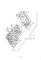
图1是屏蔽式电气接插件的透视图,接插件的各部分彼此分开着;Figure 1 is a perspective view of a shielded electrical connector with parts of the connector separated from each other;
图2是图1所示的接插件的透视图;Fig. 2 is the perspective view of connector shown in Fig. 1;
图3是图1所示的接插件其各部件部分装配后的纵向剖视图;Fig. 3 is a longitudinal sectional view of the partially assembled parts of the connector shown in Fig. 1;
图4的视图与图3类似,各部分都装配在一起;The view of Fig. 4 is similar to that of Fig. 3, and all parts are assembled together;
图5是图1所示的接插个的端子支撑板和外壳的透视图;Figure 5 is a perspective view of the terminal support plate and the housing of the connector shown in Figure 1;
图6是图1所示的接插件的局部剖视图。Fig. 6 is a partial sectional view of the connector shown in Fig. 1 .
参看图1,屏蔽插头式接插件19包括:绝缘电缆端接部分20,用以端接屏蔽多芯电缆22的绝缘导线21(图2);和绝缘插头接插部分24,接插部分24向前凸出,供与屏蔽插座式接插件(图中未示出)接合之用。插头接插部分24装有一个向前凸出的端子支撑板41支撑着多触点端子51,端子51具有导线端接部分55(图3和4),供连接到导线21之用。Referring to Fig. 1, the shielded
导电屏蔽件由单一的拉延金属前壳6和上金属后壳12以及下金属后壳14形成。前壳6中形成有空腔,这是由上壁46和下壁48以及彼此相向成一定角度的侧壁40围成的空腔。在毗邻后缘的壁46和48中配备有横向延伸的切口50,该后缘形成一个条形的支撑构件118桥接整个切口50的背面。The conductive shield is formed from a single drawn
后壳12呈单一结构,由金属板材冲压成形。后壳12由上壁52和悬垂的侧壁54组成,形成倒过来的沟槽。后壳12的后部有一个用以固定下后壳14的固定构件56从后壁58凸出来。固定构件56由上壁60和悬垂的侧壁62构成,形成一个倒过来的沟槽。上壁60中形成有凹口64,呈颇深的一个凹陷部位。板66偏离壁52的平面向前伸出。一对前伸的翼片68从板66的前沿70伸出。弯曲的旋开钩件72从两翼片68之间的前沿70伸出。The
后壳14是用金属板材料压成形的单一结构。后壳14由下壁74和直立的侧壁部分76、78组成,形成一个沟槽。横向向外转的凸缘77在侧壁部分76、78前端。板80偏离壁74的平面向前伸展。电缆应力消除构件86从后壳14的后沿84伸出,它由下壁88和直立的固定用的凸缘90构成,凸缘90的尖端即为逐渐缩小的部分92。翼片68和旋开钩件72从前缘94向前凸出,其结构与结合后壳12所介绍的类似。美国专利5,158,481介绍了后壳12和后壳14的更详细的细节。后壳14上横向伸出的凸缘114嵌入拉制的前壳6后部上横向伸出的凸缘42后面。1992年10月1日申请的美国专利955,554(15319)公开了前壳6和接插件19的更详的细节。参看图3,后壳14钩合固定到前壳6上,并将接插件41封闭起来。后壳12钩合到前壳6上,并摆向后壳14,将接插件19封闭起来。起固定作用的凸缘90后内弯,将固定构件56和电缆22(图2)包起来,解除电缆22的应力,并将后壳12和14连接起来。The
参看图1、3和4,凸出的后缓冲件43横向桥接端子支撑板41的后端,并一直延伸到该后端。缓冲件43可以例如通过模压介电材料与支撑板41构成一个整体。缓冲件43沿相对横向从延伸在缓冲件43上的导线21向外凸出。缓冲件43的后沿逐渐缩小,与接插件19端子支撑板41的中心轴线相交。Referring to Figures 1, 3 and 4, the protruding
后壳12在相应各侧壁54的前外缘上有一组推臂15。举例说,推臂15可以通过在前外缘上刻上凹槽进行加工使它们刚硬。推臂15与后外缘冲件43逐渐缩小的边缘接合,这时缓冲件43横向伸出超过导线21,推动接插件19相对于后壳12并相对于前壳6向前移。推力在轴向上通过接插件19的中间部分作用。用手使后壳12绕旋开钩件72摆动时,由于后壳12至旋开钩件72的长度是推臂15与旋开钩件72之间较短距离的倍数,因而在机械上得益。将接插件19往前推可以补偿将各装配好的部件分开、在累积性容差方面的变化,这些容差具有使接插件19相对于前壳6的接合前缘偏离所要求的位置的倾向。此外,推臂15压在缓冲件43上可以抗衡因接插件19与接合型接插件(图中未示出)接合连接所产生的插入力。The
一组后推臂16从两侧壁54横向向外凸出。推臂16是通过向外冲压侧壁54从而在侧壁54上刻上凹槽而加工出来的,形成面向前方且与后壳14的朝后外缘18接合的经剪切的前缘17。当后壳12摆向后壳14时,垂直切口23的各边缘就形成边缘18,其开口端容纳推臂16。参看图3和图4,后壳12摆动时,推臂16进入切口23中撞到边缘18上,将后壳14往前推,从而将凸缘114往前推与凸缘42的后部接合。向前推动后壳14可以补偿势必使前壳6上的凸缘42偏离后壳14上的凸缘114在累积容差上的各种变化。前壳6与后壳14、12之间的接合保证了电气上的连续性,这是使电气屏蔽起作用必不可少的条件。此外,推臂16压在连缘18上抗衡了因接插件19与接合型接插件(图中未示出)接合连接所产生的插入力。后壳12和14装配好之后,将固定凸缘90套到固定构件56上,于是凸缘90进入凹口64中,将后壳12和14固定在一起,并将电缆22夹持好,使电缆消除应力的作用。A set of push-
参看图5,端子支撑板41和各前壳6一样,是一个分立的元件,绝缘外壳61的形状则制成使其可以装入前壳6中。外壳61有一个后外腔71(图6)供容纳端子支撑板41的前端。触点端子51从端子支撑板41的前端向前凸出,支撑在外壳61的舌片75上。弹性夹持销(其中一个在44处示出)在端子支撑板41正面与端子支撑板41形成一个整体,在外壳61中钩合到从下部切开的凹口63(图中示出了其中一个)中,以防端子支撑板41与外壳61分开。Referring to FIG. 5 , the
参看图6,前壳6上的弹性销(其中一个在65处示出)斜斜地向前壳6的前接合端67伸出,并在外壳61中嵌入从下部切开的凹口(其中一个在69处示出)中,以防前壳6从外壳61脱开。前壳6的接合端67包围着外壳61的接合端73。Referring to Fig. 6, the elastic pins (one of which is shown at 65) on the
前壳6、端子支撑板41和外壳61都按容许尺寸容差范围内的尺寸制作。这些容差使各组成部分在接插件中装配或结合在一起时可以相互配合。这些容差在各组成部分结合在一起时累积起来就要以使它们在装配好的接插件中彼此相对移位。举例说,参看图6,容差使销61在凹口63中由前往后位移。容差使销65在凹口69中从前往后移位。因此,前壳6、外壳61和端子支撑板41都是会在装配好的接插件19中从各自的位置彼此相对移位的部件。The
接插件19与另一个配套的电气接插件(图中未示出)接合连接时,各部件的移位特别有害。这种在接合连接的过程中产生的位移,会使端子支撑板41相对于接合端67和外壳61及前壳6向后移动。支撑在支撑板41上的触点端子51在接合连接的过程中与支撑板41一起向后移动。在接合连接过程中是不希望触点端子向后移动的,因为触点端子51向后移动会使接插件19从另一个配套的电气接插件(图中未示出)脱开。此外,在接合连接过程中,各接触端子51接触摩擦,将触点端子51表面上不导电的氧化物及其它能在触点端子51表面之间产生不希望有的电压降的杂质除去,这是我们所希望的。接触摩擦是在触点端子51在接合连接的过程中撞击另一个配套的电气接插件时发生的。触点端子51后移动时,撞击作用就减小了。因此,触点端子51因各组成部分移位而向后移动时,接触摩擦作用减小了。按照本发明的这个特点,电气接插件19的各组成部分系装配成使其在电气接插件19与另一个配套的电气接插件(图中未示出)接合连接时阻止各组成部分的移位。Misalignment of the components is particularly detrimental when the
本发明的好处在于后壳12能在接插件19与另一个配套的接插件接合连接的过程中向前推动接插件19抗衡插入力。本发明的另一个好处在于,电气接插件19是由一些分立部件构成的,这些部件保证其接合端达到相对于接插件19的接合端预定的位置。The advantage of the present invention is that the
本发明的其它实施例、目的和优点应包括在本说明书所附权利要求书的精神实质和范围内。Other embodiments, objects and advantages of the present invention should be included within the spirit and scope of the appended claims of this specification.
Claims (9)
Applications Claiming Priority (4)
| Application Number | Priority Date | Filing Date | Title |
|---|---|---|---|
| US485993A | 1993-01-15 | 1993-01-15 | |
| US004,859 | 1993-01-15 | ||
| US007,933 | 1993-01-25 | ||
| US08/007,933US5273459A (en) | 1992-10-01 | 1993-01-25 | Connector feature for improved contact wiping |
Publications (2)
| Publication Number | Publication Date |
|---|---|
| CN1093496Atrue CN1093496A (en) | 1994-10-12 |
| CN1039563C CN1039563C (en) | 1998-08-19 |
Family
ID=26673590
Family Applications (1)
| Application Number | Title | Priority Date | Filing Date |
|---|---|---|---|
| CN94100752AExpired - LifetimeCN1039563C (en) | 1993-01-15 | 1994-01-14 | Shielded Electrical Connectors |
Country Status (5)
| Country | Link |
|---|---|
| EP (1) | EP0606739B1 (en) |
| JP (1) | JP3097891B2 (en) |
| CN (1) | CN1039563C (en) |
| BR (1) | BR9400101A (en) |
| DE (1) | DE69320019T2 (en) |
Cited By (7)
| Publication number | Priority date | Publication date | Assignee | Title |
|---|---|---|---|---|
| CN101867113A (en)* | 2009-04-16 | 2010-10-20 | 广濑电机株式会社 | electrical connector assembly |
| CN101276974B (en)* | 2007-03-30 | 2012-08-08 | 西门子公司 | Bus connector with at least two cable connections for bus lines |
| CN103918135A (en)* | 2011-10-18 | 2014-07-09 | 浩亭电子有限公司 | Plug connector |
| CN107863639A (en)* | 2017-11-09 | 2018-03-30 | 深圳市深台帏翔电子有限公司 | Electric connector |
| CN110235317A (en)* | 2017-02-03 | 2019-09-13 | 株式会社自动网络技术研究所 | Shield terminal |
| CN110235319A (en)* | 2017-02-03 | 2019-09-13 | 株式会社自动网络技术研究所 | Shield terminal |
| CN110235318A (en)* | 2017-02-03 | 2019-09-13 | 株式会社自动网络技术研究所 | Shield terminal |
Families Citing this family (7)
| Publication number | Priority date | Publication date | Assignee | Title |
|---|---|---|---|---|
| US5700164A (en)* | 1995-06-16 | 1997-12-23 | The Whitaker Corporation | Electrical connector with shield |
| GB2330022B (en)* | 1996-07-18 | 1999-08-18 | Richard Drewnicki | Electrical connectors |
| US5980325A (en)* | 1998-07-30 | 1999-11-09 | Berg Technology, Inc. | Micro miniature electrical connector and method of manufacture |
| EP1170828B1 (en)* | 2000-07-06 | 2012-01-11 | Yazaki Corporation | Protective cover |
| JP4278674B2 (en)* | 2006-10-17 | 2009-06-17 | ヒロセ電機株式会社 | Electrical connector |
| CN107546539A (en)* | 2016-06-29 | 2018-01-05 | 永泰电子(东莞)有限公司 | Shield shell combines and its wire and cable connector |
| JP7211301B2 (en)* | 2019-08-09 | 2023-01-24 | 株式会社オートネットワーク技術研究所 | connector |
Family Cites Families (4)
| Publication number | Priority date | Publication date | Assignee | Title |
|---|---|---|---|---|
| US4337989A (en)* | 1980-05-28 | 1982-07-06 | Amp Incorporated | Electromagnetic shielded connector |
| US4653836A (en)* | 1983-07-06 | 1987-03-31 | Amp Incorporated | Shielded electrical connector |
| JPH0722064Y2 (en)* | 1989-12-04 | 1995-05-17 | ホシデン株式会社 | connector |
| US5158481A (en)* | 1991-09-27 | 1992-10-27 | Amp Incorporated | Shielded electrical connector with torsioned shield interconnect |
- 1993
- 1993-12-14EPEP93310063Apatent/EP0606739B1/ennot_activeExpired - Lifetime
- 1993-12-14DEDE69320019Tpatent/DE69320019T2/ennot_activeExpired - Lifetime
- 1994
- 1994-01-13BRBR9400101Apatent/BR9400101A/ennot_activeApplication Discontinuation
- 1994-01-14CNCN94100752Apatent/CN1039563C/ennot_activeExpired - Lifetime
- 1994-01-17JPJP06017040Apatent/JP3097891B2/ennot_activeExpired - Fee Related
Cited By (11)
| Publication number | Priority date | Publication date | Assignee | Title |
|---|---|---|---|---|
| CN101276974B (en)* | 2007-03-30 | 2012-08-08 | 西门子公司 | Bus connector with at least two cable connections for bus lines |
| CN101867113A (en)* | 2009-04-16 | 2010-10-20 | 广濑电机株式会社 | electrical connector assembly |
| CN101867113B (en)* | 2009-04-16 | 2013-04-10 | 广濑电机株式会社 | Electrical connector assembly |
| CN103918135A (en)* | 2011-10-18 | 2014-07-09 | 浩亭电子有限公司 | Plug connector |
| US9466928B2 (en) | 2011-10-18 | 2016-10-11 | HARTING Electronics GmbH | Plug-in connector |
| CN110235317A (en)* | 2017-02-03 | 2019-09-13 | 株式会社自动网络技术研究所 | Shield terminal |
| CN110235319A (en)* | 2017-02-03 | 2019-09-13 | 株式会社自动网络技术研究所 | Shield terminal |
| CN110235318A (en)* | 2017-02-03 | 2019-09-13 | 株式会社自动网络技术研究所 | Shield terminal |
| CN110235319B (en)* | 2017-02-03 | 2020-11-17 | 株式会社自动网络技术研究所 | Shielding terminal |
| CN107863639A (en)* | 2017-11-09 | 2018-03-30 | 深圳市深台帏翔电子有限公司 | Electric connector |
| CN107863639B (en)* | 2017-11-09 | 2024-02-06 | 深圳市深台帏翔电子有限公司 | Electric connector |
Also Published As
| Publication number | Publication date |
|---|---|
| JPH07254454A (en) | 1995-10-03 |
| EP0606739A2 (en) | 1994-07-20 |
| EP0606739A3 (en) | 1995-11-08 |
| DE69320019D1 (en) | 1998-09-03 |
| BR9400101A (en) | 1994-08-02 |
| EP0606739B1 (en) | 1998-07-29 |
| CN1039563C (en) | 1998-08-19 |
| JP3097891B2 (en) | 2000-10-10 |
| DE69320019T2 (en) | 1998-12-17 |
Similar Documents
| Publication | Publication Date | Title |
|---|---|---|
| US5273459A (en) | Connector feature for improved contact wiping | |
| CN215299724U (en) | Shielding plate connecting conductor | |
| US6299487B1 (en) | Connector with wear-resistant engagement means | |
| EP0363170B1 (en) | Elastically supported dual cantilever beam pin-receiving electrical contact | |
| US6364706B1 (en) | Shielded electrical connector with flange support member | |
| CN1093496A (en) | Shielded electrical connector | |
| US20070178775A1 (en) | Electrical connector having an optimized conductive path | |
| CN1577991A (en) | Connector assembly | |
| CN113258355B (en) | Connector assembly | |
| CN1104380A (en) | Blind mating guides with ground contacts | |
| CN1092562A (en) | Two-piece housing for connectors | |
| US6132258A (en) | Board to board electrical connector | |
| CN1236493A (en) | Electrical plugs with reduced mating force | |
| CN1192827A (en) | Shielded electrical connectors | |
| EP0713263B1 (en) | Self-locking mating terminal structure | |
| EP3691047B1 (en) | Connector structure | |
| US6186833B1 (en) | Hybrid connector with audio jack | |
| KR100397836B1 (en) | Electric connector with spring contact terminal | |
| CN110729582A (en) | Board-to-board socket, plug and connector assembly | |
| US20040102083A1 (en) | Receptacle connector with latch arms and plug connector to be connected thereto | |
| CN211579028U (en) | Board-to-board socket, plug and connector assembly | |
| CN1618147A (en) | The structure of the connecting pins of the electrical connector | |
| JPH10284197A (en) | Electrical connector and manufacture thereof | |
| EP0185049A1 (en) | Electrical connector socket | |
| JPS61161679A (en) | Electric connector for receptacle |
Legal Events
| Date | Code | Title | Description |
|---|---|---|---|
| C06 | Publication | ||
| PB01 | Publication | ||
| C10 | Entry into substantive examination | ||
| SE01 | Entry into force of request for substantive examination | ||
| C14 | Grant of patent or utility model | ||
| GR01 | Patent grant | ||
| CX01 | Expiry of patent term | Expiration termination date:20140114 Granted publication date:19980819 | |
| CX01 | Expiry of patent term |