CN109342914B - IGBT junction temperature monitoring method, device and computer equipment - Google Patents
IGBT junction temperature monitoring method, device and computer equipmentDownload PDFInfo
- Publication number
- CN109342914B CN109342914BCN201811275513.8ACN201811275513ACN109342914BCN 109342914 BCN109342914 BCN 109342914BCN 201811275513 ACN201811275513 ACN 201811275513ACN 109342914 BCN109342914 BCN 109342914B
- Authority
- CN
- China
- Prior art keywords
- junction temperature
- current
- tested
- igbt
- igbt device
- Prior art date
- Legal status (The legal status is an assumption and is not a legal conclusion. Google has not performed a legal analysis and makes no representation as to the accuracy of the status listed.)
- Active
Links
Images


Classifications
- G—PHYSICS
- G01—MEASURING; TESTING
- G01R—MEASURING ELECTRIC VARIABLES; MEASURING MAGNETIC VARIABLES
- G01R31/00—Arrangements for testing electric properties; Arrangements for locating electric faults; Arrangements for electrical testing characterised by what is being tested not provided for elsewhere
- G01R31/26—Testing of individual semiconductor devices
- G01R31/2601—Apparatus or methods therefor
- G—PHYSICS
- G01—MEASURING; TESTING
- G01R—MEASURING ELECTRIC VARIABLES; MEASURING MAGNETIC VARIABLES
- G01R31/00—Arrangements for testing electric properties; Arrangements for locating electric faults; Arrangements for electrical testing characterised by what is being tested not provided for elsewhere
- G01R31/26—Testing of individual semiconductor devices
- G01R31/2607—Circuits therefor
- G01R31/2608—Circuits therefor for testing bipolar transistors
- G01R31/2619—Circuits therefor for testing bipolar transistors for measuring thermal properties thereof
Landscapes
- Physics & Mathematics (AREA)
- General Physics & Mathematics (AREA)
- Engineering & Computer Science (AREA)
- Microelectronics & Electronic Packaging (AREA)
- Testing Of Individual Semiconductor Devices (AREA)
Abstract
Translated fromChinese
Description
Translated fromChinese技术领域technical field
本发明涉及半导体器件测试技术领域,特别是涉及一种IGBT结温监控方法、装置及计算机设备。The invention relates to the technical field of semiconductor device testing, in particular to a method, device and computer equipment for monitoring junction temperature of an IGBT.
背景技术Background technique
半导体器件的性能和寿命受温度影响很大,尤其是对于功率器件来说。功率器件在工作过程中受大功率影响,会产生大量的热量,引起器件温度的上升。IGBT是半导体功率器件的一种,在现代电力电子技术中有广泛运用。其应用特点要求IGBT不仅要经受外界环境温度的变化,还要在生命周期内能承受多次的功率循环。IGBT在开关状态工作时,通常承受着高电压和大电流,导致器件结温上升,如果超过最高结温限制,会影响模块的电学性能和工作寿命。结温是反映IGBT模块状态的一个重要参数,实现对IGBT结温的有效监测,可以实现IGBT的过温保护,以及降低器件失效的风险等。The performance and lifetime of semiconductor devices are greatly affected by temperature, especially for power devices. Power devices are affected by high power during operation, which will generate a large amount of heat, causing the temperature of the device to rise. IGBT is a kind of semiconductor power device, which is widely used in modern power electronic technology. Its application characteristics require that IGBTs not only have to withstand changes in external ambient temperature, but also withstand multiple power cycles during their life cycle. When the IGBT is working in the on-off state, it is usually subjected to high voltage and high current, which causes the junction temperature of the device to rise. If the maximum junction temperature limit is exceeded, the electrical performance and working life of the module will be affected. The junction temperature is an important parameter reflecting the state of the IGBT module, which can effectively monitor the junction temperature of the IGBT, realize the over-temperature protection of the IGBT, and reduce the risk of device failure.
在实现过程中,发明人发现传统技术中至少存在如下问题:传统的IGBT结温监控精度低,监控可靠性低。During the implementation process, the inventor found that there are at least the following problems in the traditional technology: the traditional IGBT junction temperature monitoring accuracy is low, and the monitoring reliability is low.
发明内容SUMMARY OF THE INVENTION
基于此,有必要针对传统的IGBT结温监控精度低,监控可靠性低的问题,提供一种IGBT结温监控方法、装置及计算机设备。Based on this, it is necessary to provide an IGBT junction temperature monitoring method, device and computer equipment for the problems of low monitoring accuracy and low monitoring reliability of the traditional IGBT junction temperature.
为了实现上述目的,本发明实施例提供了一种IGBT结温监控方法,包括以下步骤:In order to achieve the above purpose, an embodiment of the present invention provides an IGBT junction temperature monitoring method, including the following steps:
获取与待测IGBT器件的集电极电流对应的饱和导通压降;集电极电流为加热大电流或恒定小电流;Obtain the saturated on-state voltage drop corresponding to the collector current of the IGBT device to be tested; the collector current is a large heating current or a small constant current;
基于结温和饱和导通压降拟合曲面,获取对应饱和导通压降的当前结温;Fit the surface based on the junction temperature and the saturated conduction voltage drop to obtain the current junction temperature corresponding to the saturated conduction voltage drop;
在当前结温小于设定结温时,增大输入待测IGBT器件的集电极加热大电流;When the current junction temperature is lower than the set junction temperature, increase the collector heating current input to the IGBT device to be tested;
在当前结温大于设定结温,且未到达预设加热工作时间时,减小输入待测IGBT器件的集电极的加热大电流;When the current junction temperature is greater than the set junction temperature and the preset heating working time is not reached, reduce the heating current input to the collector of the IGBT device to be tested;
在当前结温大于设定结温,且到达预设加热工作时间时,向待测IGBT器件的集电极输入恒定小电流,并冷却待测IGBT器件。When the current junction temperature is greater than the set junction temperature and the preset heating working time is reached, a constant small current is input to the collector of the IGBT device to be tested, and the IGBT device to be tested is cooled.
另一方面,本发明实施例还提供了一种IGBT结温监控装置,包括:On the other hand, an embodiment of the present invention also provides an IGBT junction temperature monitoring device, including:
饱和导通压降获取单元,用于获取与待测IGBT器件的集电极电流对应的饱和导通压降;集电极电流为加热大电流或恒定小电流;The saturation conduction voltage drop acquisition unit is used to obtain the saturated conduction voltage drop corresponding to the collector current of the IGBT device to be tested; the collector current is a large heating current or a small constant current;
结温获取单元,用于基于结温和饱和导通压降拟合曲面,获取对应饱和导通压降的当前结温;The junction temperature acquisition unit is used to fit the curved surface based on the junction temperature and the saturated conduction voltage drop, and obtain the current junction temperature corresponding to the saturated conduction voltage drop;
升温处理单元,用于在当前结温小于设定结温时,增大输入待测IGBT器件的集电极的加热大电流;The heating processing unit is used to increase the heating current input to the collector of the IGBT device to be tested when the current junction temperature is lower than the set junction temperature;
降温处理单元,用于在当前结温大于设定结温,且未到达预设加热工作时间时,减小输入待测IGBT器件的集电极的加热大电流;在当前结温大于设定结温,且到达预设加热工作时间时,向待测IGBT器件的集电极输入恒定小电流,并冷却待测IGBT器件。The cooling processing unit is used to reduce the large heating current input to the collector of the IGBT device to be tested when the current junction temperature is greater than the set junction temperature and does not reach the preset heating working time; when the current junction temperature is greater than the set junction temperature , and when the preset heating working time is reached, a constant small current is input to the collector of the IGBT device to be tested, and the IGBT device to be tested is cooled.
另一方面,本发明实施例还提供了一种计算机设备,包括存储器和处理器,存储器存储有计算机程序,处理器执行计算机程序时实现上述任意一项IGBT结温监控方法的步骤。On the other hand, an embodiment of the present invention also provides a computer device, including a memory and a processor, the memory stores a computer program, and the processor implements any of the steps of the above-mentioned IGBT junction temperature monitoring method when the computer program is executed.
另一方面,本发明实施例还提供了一种计算机可读存储介质,其上存储有计算机程序,计算机程序被处理器执行时实现上述任一项IGBT结温监控方法的步骤。On the other hand, an embodiment of the present invention also provides a computer-readable storage medium on which a computer program is stored, and when the computer program is executed by a processor, implements the steps of any of the foregoing IGBT junction temperature monitoring methods.
上述技术方案中的一个技术方案具有如下优点和有益效果:A technical scheme in the above-mentioned technical scheme has the following advantages and beneficial effects:
将待测IGBT器件的饱和导通压降作为温敏参数,基于结温和饱和导通压降拟合曲面,在待测IGBT器件升温阶段,获取对应饱和导通压降的当前结温,通过适当改变集电极电流来控制结温,使当前结温稳定在设定的控制值。在待测IGBT器件降温阶段,获取对应饱和导通压降的当前结温,通过向待测IGBT器件的集电极施加恒定小电流并启动冷却模式来控制结温,使当前结温稳定在设定的控制值。本发明实施例能够实现对待测IGBT器件结温的实时监控,提高了IGBT结温监控精度,以及提高了IGBT结温监控可靠性。Taking the saturated on-state voltage drop of the IGBT device to be tested as a temperature-sensitive parameter, the curved surface is fitted based on the junction temperature and the saturated on-state voltage drop. During the heating stage of the IGBT device to be tested, the current junction temperature corresponding to the saturated on-state voltage drop is obtained. Change the collector current to control the junction temperature, so that the current junction temperature is stable at the set control value. During the cooling stage of the IGBT device to be tested, the current junction temperature corresponding to the saturated on-state voltage drop is obtained, and the junction temperature is controlled by applying a constant small current to the collector of the IGBT device to be tested and starting the cooling mode, so that the current junction temperature is stabilized at the set point control value. The embodiments of the present invention can realize real-time monitoring of the junction temperature of the IGBT device to be measured, improve the monitoring accuracy of the IGBT junction temperature, and improve the reliability of the IGBT junction temperature monitoring.
附图说明Description of drawings
图1为一个实施例中IGBT结温监控方法的应用环境图;Fig. 1 is the application environment diagram of the IGBT junction temperature monitoring method in one embodiment;
图2为一个实施例中IGBT结温监控方法的第一流程示意图;2 is a first schematic flow chart of a method for monitoring junction temperature of an IGBT in one embodiment;
图3为一个实施例中IGBT结温监控方法的第二流程示意图;3 is a second schematic flowchart of a method for monitoring junction temperature of an IGBT in one embodiment;
图4为一个实施例中IGBT结温监控方法的第三流程示意图;4 is a third schematic flowchart of a method for monitoring junction temperature of an IGBT in one embodiment;
图5为一个实施例中失效循环次数处理步骤的流程示意图;FIG. 5 is a schematic flowchart of processing steps for the number of failure cycles in one embodiment;
图6为一个实施例中IGBT寿命值获取步骤的流程示意图;6 is a schematic flowchart of a step of obtaining a life value of an IGBT in one embodiment;
图7为一个实施例中结温、集电极电流和饱和导通压降的拟合曲面示意图;FIG. 7 is a schematic diagram of a fitting curved surface of junction temperature, collector current, and saturation conduction voltage drop in one embodiment;
图8为一个实施例中IGBT结温监控装置的结构示意图;8 is a schematic structural diagram of an IGBT junction temperature monitoring device in one embodiment;
图9为一个实施例中计算机设备的结构示意图;9 is a schematic structural diagram of a computer device in one embodiment;
图10为一个实施例中计算机设备的数据采集界面示意图;10 is a schematic diagram of a data acquisition interface of a computer device in one embodiment;
图11为一个实施例中计算机设备的结温监控界面示意图;11 is a schematic diagram of a junction temperature monitoring interface of a computer device in one embodiment;
图12为一个实施例中计算机设备的结温监控流程示意图。FIG. 12 is a schematic diagram of a junction temperature monitoring process flow of a computer device in one embodiment.
具体实施方式Detailed ways
为了便于理解本申请,下面将参照相关附图对本申请进行更全面的描述。附图中给出了本申请的首选实施例。但是,本申请可以以许多不同的形式来实现,并不限于本文所描述的实施例。相反地,提供这些实施例的目的是使对本申请的公开内容更加透彻全面。In order to facilitate understanding of the present application, the present application will be described more fully below with reference to the related drawings. Preferred embodiments of the present application are shown in the accompanying drawings. However, the application may be implemented in many different forms and is not limited to the embodiments described herein. Rather, these embodiments are provided so that this disclosure will be thorough and complete.
除非另有定义,本文所使用的所有的技术和科学术语与属于本申请的技术领域的技术人员通常理解的含义相同。本文中在本申请的说明书中所使用的术语只是为了描述具体的实施例的目的,不是旨在于限制本申请。本文所使用的术语“及/或”包括一个或多个相关的所列项目的任意的和所有的组合。Unless otherwise defined, all technical and scientific terms used herein have the same meaning as commonly understood by one of ordinary skill in the technical field to which this application belongs. The terms used herein in the specification of the application are for the purpose of describing specific embodiments only, and are not intended to limit the application. As used herein, the term "and/or" includes any and all combinations of one or more of the associated listed items.
传统的IGBT结温监控过程中,对IGBT结温监测方法主要有:红外热探测法、物理测量法、RC热网络法和温敏参数法。其中,红外热探测法使用红外热成像仪对芯片进行监测,可较准确地获取IGBT的温度分布,但需要开封去除芯片表面包封模块后,将红外镜头聚焦到芯片表面,因而一方面会因开封破坏原有热平衡环境而导致结温偏移,另一方面因需要红外镜头聚焦而无法做到在试验过程中进行在线监测;物理测量法是利用热敏元件(如热电阻)进行接触式测量,监测精度受到热敏元件安装和使用方法的影响,且测量响应时间长,不能实时快速捕捉开关状态结温的瞬时变化信息;RC热网络法搭建电损耗模型和热网络模型来进行模拟,其局限性在于器件工作时的瞬态热阻、热容和功率损耗不易获取,模型的搭建也依赖于一些经验参数;温敏参数法是利用IGBT的某个温敏特性参数与结温之间的关系,通过监测这些温敏参数来获得结温。但温敏参数易受干扰且较难测量,且需要在大功率试验条件和小电流测试条件之间切换,切换过程会带来结温急剧降低和电子噪声等问题,测试精度较低,且属于非在线测量。In the traditional IGBT junction temperature monitoring process, the IGBT junction temperature monitoring methods mainly include: infrared thermal detection method, physical measurement method, RC thermal network method and temperature-sensitive parameter method. Among them, the infrared thermal detection method uses an infrared thermal imager to monitor the chip, which can accurately obtain the temperature distribution of the IGBT, but it needs to open the package to remove the encapsulated module on the chip surface, and then focus the infrared lens on the chip surface. Kaifeng destroys the original thermal equilibrium environment and causes the junction temperature to shift. On the other hand, it is impossible to perform online monitoring during the test due to the need for infrared lens focusing; the physical measurement method is to use thermal elements (such as thermal resistance) for contact measurement , the monitoring accuracy is affected by the installation and use method of the thermal element, and the measurement response time is long, and the instantaneous change information of the junction temperature in the switching state cannot be quickly captured in real time; the RC thermal network method builds an electrical loss model and a thermal network model for simulation. The limitation is that the transient thermal resistance, thermal capacitance and power loss during operation of the device are not easy to obtain, and the construction of the model also depends on some empirical parameters; the temperature-sensitive parameter method uses the relationship between a certain temperature-sensitive characteristic parameter of the IGBT and the junction temperature. The junction temperature is obtained by monitoring these temperature-sensitive parameters. However, temperature-sensitive parameters are easily disturbed and difficult to measure, and they need to be switched between high-power test conditions and low-current test conditions. The switching process will bring about problems such as a sharp drop in junction temperature and electronic noise. The test accuracy is low, and it belongs to Offline measurement.
传统的IGBT结温监控过程中,对IGBT结温控制方法主要有:一种为热阻计算或壳温近似法,该方法误差较大,且无法解决试验过程中由于器件退化或者安装状态变化带来的热阻变化问题;另一种为开关式的结温测量法,该方法需要在大电流加热条件和小电流测试条件之间切换,测试延迟会使器件结温瞬间降低,影响对器件结温的正确判断,也可能会破坏试验本身需要的结温变化要求,IGBT结温监控的可靠性低。In the traditional IGBT junction temperature monitoring process, the main control methods for the IGBT junction temperature are: one is the thermal resistance calculation or the case temperature approximation method, which has a large error and cannot solve the problems caused by the degradation of the device or the change of the installation state during the test process. The other is the switch-type junction temperature measurement method, which needs to switch between high-current heating conditions and low-current testing conditions, and the test delay will reduce the junction temperature of the device instantly, which will affect the junction temperature of the device. The correct judgment of temperature may also destroy the junction temperature change requirements required by the test itself, and the reliability of IGBT junction temperature monitoring is low.
而本发明各实施例中,能够通过将待测IGBT器件的饱和导通压降作为温敏参数,基于结温和饱和导通压降拟合曲面,在待测IGBT器件升温阶段,获取对应饱和导通压降的当前结温,通过适当改变集电极电流来控制结温,使当前结温稳定在设定的控制值。在待测IGBT器件降温阶段,获取对应饱和导通压降的当前结温,通过向待测IGBT器件的集电极施加恒定小电流并启动冷却模式来控制结温,使当前结温稳定在设定的控制值。本发明实施例能够实现对待测IGBT器件结温的实时监控,提高了IGBT结温监控精度,以及提高了IGBT结温监控可靠性。However, in each embodiment of the present invention, the saturated conduction voltage drop of the IGBT device to be tested can be used as a temperature-sensitive parameter, and the curved surface can be fitted based on the junction temperature and the saturated conduction voltage drop, and the corresponding saturation conduction voltage can be obtained during the heating stage of the IGBT device to be tested. Through the current junction temperature of the voltage drop, the junction temperature is controlled by appropriately changing the collector current, so that the current junction temperature is stabilized at the set control value. During the cooling stage of the IGBT device to be tested, the current junction temperature corresponding to the saturated on-state voltage drop is obtained, and the junction temperature is controlled by applying a constant small current to the collector of the IGBT device to be tested and starting the cooling mode, so that the current junction temperature is stabilized at the set point control value. The embodiments of the present invention can realize real-time monitoring of the junction temperature of the IGBT device to be measured, improve the monitoring accuracy of the IGBT junction temperature, and improve the reliability of the IGBT junction temperature monitoring.
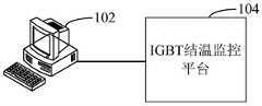
本申请提供的IGBT结温监控方法,可以应用于如图1所示的应用环境中。其中,应用环境可以是IGBT器件的功率循环可靠性试验平台,计算机设备102与用于监控待测IGBT器件的IGBT结温监控平台连接。计算机设备可获取与待测IGBT器件的集电极电流对应的饱和导通压降;基于结温和饱和导通压降拟合曲面,获取对应饱和导通压降的当前结温;在当前结温小于设定结温时,增大向待测IGBT器件的集电极输入的加热大电流;在当前结温大于设定结温,且未到达预设加热工作时间时,减小输入待测IGBT器件的集电极的加热大电流;在当前结温大于设定结温,且到达预设加热工作时间时,向待测IGBT器件的集电极输入恒定小电流,并冷却待测IGBT器件。进而实现对待测IGBT器件结温的实时监控。其中,计算机设备102可以但不限于是各种个人计算机、笔记本电脑和工控机;待测IGBT器件可装设在IGBT结温监控平台104上。The IGBT junction temperature monitoring method provided in this application can be applied to the application environment shown in FIG. 1 . The application environment may be a power cycle reliability test platform of the IGBT device, and the
在一个实施例中,如图2所示,提供了一种IGBT结温监控方法,以该方法应用于图1中的计算机设备为例进行说明,包括以下步骤:In one embodiment, as shown in FIG. 2 , a method for monitoring junction temperature of an IGBT is provided, and the method is applied to the computer equipment in FIG. 1 as an example to illustrate, including the following steps:
步骤S210,获取与待测IGBT器件的集电极电流对应的饱和导通压降;集电极电流为加热大电流或恒定小电流。In step S210, the saturated on-state voltage drop corresponding to the collector current of the IGBT device to be tested is obtained; the collector current is a large heating current or a small constant current.
其中,饱和导通压降指的是在栅极电压驱动下,IGBT工作与饱和区,IGBT集电极与发射极之间的电压差。集电极电流指的是IGBT集电极的电流。加热大电流指的是待测IGBT器件工作时的加热电流;加热大电流的取值大小可根据待测IGBT器件的特性以及实际实验过程得到,例如,加热大电流的脉宽可以是几十秒。恒定小电流指的是电流值较小的恒定电流;恒定小电流的取值大小可根据待测IGBT器件的特性以及实际实验过程得到,例如,恒定小电流的取值范围可以是10mA(毫安)至100mA。Among them, the saturated turn-on voltage drop refers to the voltage difference between the IGBT collector and the emitter under the gate voltage drive, the IGBT works and the saturation region. Collector current refers to the current of the IGBT collector. The high heating current refers to the heating current when the IGBT device to be tested is working; the value of the high heating current can be obtained according to the characteristics of the IGBT device to be tested and the actual experimental process. For example, the pulse width of the high heating current can be several tens of seconds. . The constant small current refers to a constant current with a small current value; the value of the constant small current can be obtained according to the characteristics of the IGBT device to be tested and the actual experimental process. For example, the value range of the constant small current can be 10mA (milliampere ) to 100mA.
具体地,需要对待测IGBT器件结温监控试验时,驱动待测IGBT器件的栅极,且对待测IGBT器件输入集电极电流,进而获取与待测IGBT器件的集电极电流对应的饱和导通压降。例如,对待测IGBT器件的集电极输入加热大电流时,可获取对应脉冲大电流的饱和导通压降;对待测IGBT器件的集电极输入恒定小电流时,可获取对应恒定小电流的饱和导通压降。Specifically, when the junction temperature monitoring test of the IGBT device to be tested is required, the gate of the IGBT device to be tested is driven, and the collector current of the IGBT device to be tested is input to obtain the saturated on-voltage corresponding to the collector current of the IGBT device to be tested. drop. For example, when a large current is input to the collector of the IGBT device to be tested, the saturation conduction voltage drop corresponding to the large pulse current can be obtained; when a constant small current is input to the collector of the IGBT device to be tested, the saturation conduction corresponding to the small constant current can be obtained. through pressure drop.
步骤S220,基于结温和饱和导通压降拟合曲面,获取对应饱和导通压降的当前结温。In step S220, a curved surface is fitted based on the junction temperature and the saturated conduction voltage drop, and a current junction temperature corresponding to the saturated conduction voltage drop is obtained.
其中,结温和饱和导通压降拟合曲面可通过待测IGBT器件的结温和饱和导通压降的关系得到的。当前结温指的是待测IGBT器件当前的结温。Among them, the fitting surface of the junction temperature and the saturation conduction voltage drop can be obtained from the relationship between the junction temperature and the saturation conduction voltage drop of the IGBT device to be tested. The current junction temperature refers to the current junction temperature of the IGBT device to be tested.
具体地,基于结温和饱和导通压降拟合曲面处理获取到的饱和导通压降,进而得到对应饱和导通压降的当前结温。Specifically, based on the junction temperature and the saturated on-state voltage drop, the saturated on-state voltage drop obtained by fitting the curved surface is processed, and then the current junction temperature corresponding to the saturated on-state voltage drop is obtained.
步骤S230,在当前结温小于设定结温时,增大输入待测IGBT器件的集电极的加热大电流。Step S230, when the current junction temperature is lower than the set junction temperature, increase the large heating current input to the collector of the IGBT device to be tested.
其中,设定结温指的是预设的控制结温。The set junction temperature refers to the preset control junction temperature.
具体地,根据获取到的待测IGBT器件的当前结温,判断待测IGBT器件的当前结温是否超出预设值。在当前结温小于设定结温时,可向待测IGBT器件的集电极增大输入加热大电流,使得待测IGBT器件的结温上升。Specifically, according to the obtained current junction temperature of the IGBT device to be tested, it is determined whether the current junction temperature of the IGBT device to be tested exceeds a preset value. When the current junction temperature is lower than the set junction temperature, a large heating current can be input to the collector of the IGBT device to be tested, so that the junction temperature of the IGBT device to be tested rises.
进一步的,向待测IGBT器件的集电极输入加热大电流后,若待测IGBT器件的当前结温还未到达设定结温,则可调整(增大)脉冲大电流的大小,使得待测IGBT器件的结温继续上升,直至当前结温达到设定结温,实现待测IGBT器件升温阶段的监控。Further, after a large heating current is input to the collector of the IGBT device to be tested, if the current junction temperature of the IGBT device to be tested has not reached the set junction temperature, the magnitude of the large pulse current can be adjusted (increased), so that the large current of the pulse to be tested can be adjusted (increased). The junction temperature of the IGBT device continues to rise until the current junction temperature reaches the set junction temperature, so as to monitor the heating stage of the IGBT device to be tested.
步骤S240,在当前结温大于设定结温,且未到达预设加热工作时间时,减小输入待测IGBT器件的集电极的加热大电流。Step S240 , when the current junction temperature is greater than the set junction temperature and the preset heating working time is not reached, reduce the large heating current input to the collector of the IGBT device to be tested.
具体地,根据获取到的待测IGBT器件的当前结温,判断待测IGBT器件的当前结温是否超出预设值。在当前结温大于设定结温时,可触发对应预设加热工作时间的计时器,在未到达预设加热工作时间时,减小输入待测IGBT器件的集电极的加热大电流,使得待测IGBT器件的结温下降。Specifically, according to the obtained current junction temperature of the IGBT device to be tested, it is determined whether the current junction temperature of the IGBT device to be tested exceeds a preset value. When the current junction temperature is greater than the set junction temperature, the timer corresponding to the preset heating working time can be triggered, and when the preset heating working time is not reached, the large heating current input to the collector of the IGBT device to be tested is reduced, so that the Measure the junction temperature drop of the IGBT device.
步骤S250,在当前结温大于设定结温,且到达预设加热工作时间时,向待测IGBT器件的集电极输入恒定小电流,并冷却待测IGBT器件。Step S250, when the current junction temperature is greater than the set junction temperature and reaches the preset heating working time, input a constant small current to the collector of the IGBT device to be tested, and cool the IGBT device to be tested.
具体地,根据获取到的待测IGBT器件的当前结温,判断待测IGBT器件的当前结温是否超出预设值。在当前结温大于设定结温时,且到达预设加热工作时间时,可向待测IGBT器件的集电极输入恒定小电流,并冷却待测IGBT器件,使得待测IGBT器件的结温下降。Specifically, according to the obtained current junction temperature of the IGBT device to be tested, it is determined whether the current junction temperature of the IGBT device to be tested exceeds a preset value. When the current junction temperature is greater than the set junction temperature, and when the preset heating working time is reached, a constant small current can be input to the collector of the IGBT device to be tested, and the IGBT device to be tested can be cooled, so that the junction temperature of the IGBT device to be tested drops .
进一步的,向待测IGBT器件的集电极输入恒定小电流,并冷却待测IGBT器件后,若待测IGBT器件的当前结温还未到达设定结温,则继续冷却待测IGBT器件,使得待测IGBT器件的结温继续下降,直至当前结温达到设定结温,实现待测IGBT器件降温阶段的监控。Further, input a constant small current to the collector of the IGBT device to be tested, and after cooling the IGBT device to be tested, if the current junction temperature of the IGBT device to be tested has not reached the set junction temperature, continue to cool the IGBT device to be tested, so that The junction temperature of the IGBT device to be tested continues to drop until the current junction temperature reaches the set junction temperature, so as to monitor the cooling stage of the IGBT device to be tested.
在一个具体的实施例中,步骤S220之后包括步骤:In a specific embodiment, the steps after step S220 include:
在当前结温等于预设结温时,保持输入待测IGBT器件的集电极电流,以使当前结温保持预设结温保持时间。When the current junction temperature is equal to the preset junction temperature, the collector current input to the IGBT device to be tested is maintained, so that the current junction temperature is maintained for the preset junction temperature holding time.
具体地,根据获取到的待测IGBT器件的当前结温,判断待测IGBT器件的当前结温是否等于预设值。在当前结温等于设定结温时,判断是否达到预设的结温保持时间,在未到达预设结温保持时间时,保持输入待测IGBT器件的集电极电流,以使当前结温保持预设结温保持时间。Specifically, according to the obtained current junction temperature of the IGBT device to be tested, it is determined whether the current junction temperature of the IGBT device to be tested is equal to the preset value. When the current junction temperature is equal to the set junction temperature, it is judged whether the preset junction temperature holding time is reached, and when the preset junction temperature holding time is not reached, the collector current input to the IGBT device to be tested is maintained to keep the current junction temperature Preset junction temperature hold time.
基于本实施例,将待测IGBT器件的饱和导通压降作为温敏参数,基于结温和饱和导通压降拟合曲面,在待测IGBT器件升温阶段,获取对应饱和导通压降的当前结温,通过适当改变集电极电流来控制结温,使当前结温稳定在设定的控制值。在待测IGBT器件降温阶段,获取对应饱和导通压降的当前结温,通过向待测IGBT器件的集电极施加恒定小电流并启动冷却模式来控制结温,使当前结温稳定在设定的控制值。进而能够实现对待测IGBT器件结温的实时监控,提高了IGBT结温监控精度,以及提高了IGBT结温监控可靠性。Based on this embodiment, the saturated on-state voltage drop of the IGBT device to be tested is used as a temperature-sensitive parameter, and the curved surface is fitted based on the junction temperature and the saturated on-state voltage drop. During the heating stage of the IGBT device to be tested, the current value corresponding to the saturated on-state voltage drop is obtained. The junction temperature is controlled by appropriately changing the collector current, so that the current junction temperature is stabilized at the set control value. During the cooling stage of the IGBT device to be tested, the current junction temperature corresponding to the saturated on-state voltage drop is obtained, and the junction temperature is controlled by applying a constant small current to the collector of the IGBT device to be tested and starting the cooling mode, so that the current junction temperature is stabilized at the set point control value. Furthermore, the real-time monitoring of the junction temperature of the IGBT device to be measured can be realized, the monitoring accuracy of the IGBT junction temperature is improved, and the reliability of the IGBT junction temperature monitoring is improved.
在一个实施例中,如图3所示,提供了一种IGBT结温监控方法,以该方法应用于图1中的计算机设备为例进行说明,包括以下步骤:In one embodiment, as shown in FIG. 3 , a method for monitoring junction temperature of an IGBT is provided, and the method is applied to the computer equipment in FIG. 1 as an example to illustrate, including the following steps:
步骤S310,对设定测试温度的待测IGBT器件施加恒定小电流,获取对应测试结温及恒定小电流的测试饱和导通压降。In step S310, a constant small current is applied to the IGBT device to be tested with the set test temperature, and the test saturation conduction voltage drop corresponding to the test junction temperature and the constant small current is obtained.
其中,测试温度指的是预先设定的温度,例如,将待测IGBT器件在设定的测试温度环境下保持一段时间(例如30分钟)后,可将设定的测试温度作为待测IGBT器件的结温。在设定的测试结温下,对待测IGBT器件输入恒定小电流,进而可获取到对应的测试饱和导通压降。Among them, the test temperature refers to the preset temperature. For example, after the IGBT device to be tested is kept in the set test temperature environment for a period of time (for example, 30 minutes), the set test temperature can be used as the IGBT device to be tested. junction temperature. Under the set test junction temperature, a constant small current is input to the IGBT device to be tested, and then the corresponding test saturated on-voltage drop can be obtained.
具体地,将待测IGBT器件放置在设定的测试温度环境下,对设定测试温度的待测IGBT器件施加恒定小电流,进而可获取对应测试结温及恒定小电流的测试饱和导通压降。Specifically, the IGBT device to be tested is placed in the set test temperature environment, and a constant small current is applied to the IGBT device to be tested at the set test temperature, so as to obtain the test saturated on-voltage corresponding to the test junction temperature and the constant small current. drop.
步骤S320,对测试结温、恒定小电流和测试饱和导通压降进行拟合,得到在恒定小电流下的结温和饱和导通压降拟合曲面。Step S320 , fitting the test junction temperature, the constant small current and the test saturation conduction voltage drop to obtain a fitting surface of the junction temperature and the saturation conduction voltage drop under the constant small current.
具体地,对测试结温、恒定小电流和测试饱和导通压降进行拟合处理,进而得到在恒定小电流下的结温和饱和导通压降拟合曲面。Specifically, the fitting process is performed on the test junction temperature, the constant small current and the test saturation conduction voltage drop, and then the fitting surface of the junction temperature and the saturation conduction voltage drop under the constant small current is obtained.
步骤S330,获取与待测IGBT器件的恒定小电流对应的饱和导通压降。Step S330, obtaining the saturated on-state voltage drop corresponding to the constant small current of the IGBT device to be tested.
步骤S340,基于在恒定小电流下的结温和饱和导通压降拟合曲面,获取对应饱和导通压降的当前结温。In step S340, a curved surface is fitted based on the junction temperature and the saturation conduction voltage drop under a constant small current, and the current junction temperature corresponding to the saturation conduction voltage drop is obtained.
步骤S350,在当前结温大于设定结温,且未到达预设加热工作时间时,减小输入待测IGBT器件的集电极的加热大电流;在当前结温大于设定结温,且到达预设加热工作时间时,向待测IGBT器件的集电极输入恒定小电流,并冷却待测IGBT器件。Step S350, when the current junction temperature is greater than the set junction temperature, and the preset heating working time is not reached, reduce the large heating current input to the collector of the IGBT device to be tested; when the current junction temperature is greater than the set junction temperature and reach the When the heating working time is preset, a constant small current is input to the collector of the IGBT device to be tested, and the IGBT device to be tested is cooled.
其中,上述步骤S330、步骤S340和步骤S350的具体内容过程可参考上文内容,此处不再赘述。The specific content and process of the above steps S330, S340 and S350 may refer to the above content, which will not be repeated here.
具体地,将待测IGBT器件放置在设定的测试温度环境下。驱动待测IGBT器件的栅极,例如向待测IGBT器件施加栅极电压,使得待测IGBT器件充分导通。向待测IGBT器件集电极施加恒定小电流,采集待测IGBT器件的集电极与发射极之间的测试饱和导通压降,进而获取到对应测试结温及恒定小电流的测试饱和导通压降。对测试结温、恒定小电流和测试饱和导通压降进行拟合处理,进而得到在恒定小电流下的结温和饱和导通压降拟合曲面。在需要对待测IGBT器件进行降温处理时,即可根据在恒定小电流下的结温和饱和导通压降拟合曲面,获取对应饱和导通压降的当前结温;根据当前结温对待测IGBT器件进行冷却,实现对待测IGBT器件在降温阶段的监控。Specifically, the IGBT device to be tested is placed in a set test temperature environment. The gate of the IGBT device to be tested is driven, for example, a gate voltage is applied to the IGBT device to be tested, so that the IGBT device to be tested is fully turned on. Apply a constant small current to the collector of the IGBT device to be tested, collect the test saturated on-voltage drop between the collector and the emitter of the IGBT device to be tested, and then obtain the test saturated on-voltage corresponding to the test junction temperature and constant small current drop. Fitting is performed on the test junction temperature, constant small current and test saturation conduction voltage drop, and then the fitting surface of the junction temperature and saturation conduction voltage drop under constant small current is obtained. When the IGBT device to be tested needs to be cooled down, the curved surface can be fitted according to the junction temperature and the saturation conduction voltage drop under constant small current, and the current junction temperature corresponding to the saturated conduction voltage drop can be obtained; according to the current junction temperature of the IGBT to be tested The device is cooled to realize the monitoring of the IGBT device to be tested in the cooling stage.
进一步的,可设定初始的测试温度X,在该温度稳定停留预设时间后,将待测IGBT器件的结温确认为设定的测试温度。设定输入集电极的恒定小电流,采集并记录在该测试温度时对应恒定小电流下的测试饱和导通压降。设定测试温度的间隔为Y,依次在(X+NY)(N为整数)温度下采集测试饱和导通压降。通过拟合测试结温、恒定小电流和测试饱和导通压降,进而可构建得到在恒定小电流下的结温和饱和导通压降拟合曲面。Further, an initial test temperature X can be set, and after the temperature stays stable for a preset time, the junction temperature of the IGBT device to be tested is confirmed as the set test temperature. Set the constant small current of the input collector, collect and record the test saturation conduction voltage drop corresponding to the constant small current at the test temperature. Set the test temperature interval as Y, and collect the test saturation conduction voltage drop at the temperature of (X+NY) (N is an integer) in turn. By fitting the test junction temperature, constant small current and test saturation conduction voltage drop, the fitting surface of junction temperature and saturation conduction voltage drop under constant small current can be constructed.
基于本实施例,基于结温和饱和导通压降拟合曲面,在待测IGBT器件降温阶段,获取对应饱和导通压降的当前结温,通过向待测IGBT器件的集电极施加恒定小电流并启动冷却模式来控制结温,使当前结温稳定在设定的控制值。进而能够实现对待测IGBT器件结温的实时监控,在提高IGBT结温测试效率,同时提高了IGBT结温测试精度,以及提高了IGBT结温监控可靠性。Based on this embodiment, the curved surface is fitted based on the junction temperature and the saturated conduction voltage drop. During the cooling stage of the IGBT device to be tested, the current junction temperature corresponding to the saturated conduction voltage drop is obtained, and a constant small current is applied to the collector of the IGBT device to be tested. And start the cooling mode to control the junction temperature, so that the current junction temperature is stable at the set control value. Furthermore, the real-time monitoring of the junction temperature of the IGBT device to be measured can be realized, the IGBT junction temperature test efficiency is improved, the IGBT junction temperature test accuracy is improved, and the IGBT junction temperature monitoring reliability is improved.
在一个实施例中,如图4所示,提供了一种IGBT结温监控方法,以该方法应用于图1中的计算机设备为例进行说明,包括以下步骤:In one embodiment, as shown in FIG. 4 , a method for monitoring junction temperature of an IGBT is provided, and the method is applied to the computer equipment in FIG. 1 as an example to illustrate, including the following steps:
步骤S410,对设定测试温度的待测IGBT器件施加脉冲大电流,获取对应测试结温及脉冲大电流的测试饱和导通压降;脉冲大电流为不引起待测IGBT器件自热温升的电流。Step S410, applying a large pulse current to the IGBT device to be tested with the set test temperature, and obtaining the test saturation conduction voltage drop corresponding to the test junction temperature and the high pulse current; current.
其中,脉冲大电流可用来标定拟合曲面,脉冲大电流的脉宽可以是几毫秒。在设定的测试结温下,对待测IGBT器件输入脉冲大电流,进而可获取到对应的测试饱和导通压降。Among them, the high pulse current can be used to calibrate the fitting surface, and the pulse width of the high pulse current can be several milliseconds. Under the set test junction temperature, a large pulse current is input to the IGBT device to be tested, and then the corresponding test saturation conduction voltage drop can be obtained.
具体地,将待测IGBT器件放置在设定的测试温度环境下,对设定测试温度的待测IGBT器件施加脉冲大电流,进而可获取对应测试结温及脉冲大电流的测试饱和导通压降。Specifically, the IGBT device to be tested is placed in a set test temperature environment, and a large pulse current is applied to the IGBT device to be tested at the set test temperature, so as to obtain the test saturated on-voltage corresponding to the test junction temperature and the high pulse current. drop.
步骤S420,对测试结温、脉冲大电流和测试饱和导通压降进行拟合,得到在脉冲大电流下的结温和饱和导通压降拟合曲面。Step S420: Fitting the test junction temperature, the high pulse current and the test saturation conduction voltage drop to obtain a fitting surface of the junction temperature and the saturation conduction voltage drop under the high pulse current.
具体地,对测试结温、脉冲大电流和测试饱和导通压降进行拟合处理,进而得到在脉冲大电流下的结温和饱和导通压降拟合曲面。Specifically, the fitting process is performed on the test junction temperature, the high pulse current and the test saturation conduction voltage drop, and then the fitting surface of the junction temperature and the saturation conduction voltage drop under the high pulse current is obtained.
步骤S430,获取与待测IGBT器件的加热大电流对应的饱和导通压降。In step S430, the saturated on-state voltage drop corresponding to the large heating current of the IGBT device to be tested is obtained.
步骤S440,基于在脉冲大电流下的结温和饱和导通压降拟合曲面,获取对应饱和导通压降的当前结温。In step S440, a curved surface is fitted based on the junction temperature and the saturation conduction voltage drop under the high pulse current, and the current junction temperature corresponding to the saturation conduction voltage drop is obtained.
步骤S450,在当前结温小于设定结温时,增大输入待测IGBT器件的集电极的加热大电流。In step S450, when the current junction temperature is lower than the set junction temperature, the large heating current input to the collector of the IGBT device to be tested is increased.
其中,上述步骤S430、步骤S440和步骤S450的具体内容过程可参考上文内容,此处不再赘述。The specific content and process of the above-mentioned steps S430, S440 and S450 may refer to the above-mentioned content, which will not be repeated here.
具体地,将待测IGBT器件放置在设定的测试温度环境下。驱动待测IGBT器件的栅极,例如向待测IGBT器件施加栅极电压,使得待测IGBT器件充分导通。向待测IGBT器件集电极施加脉冲大电流,采集待测IGBT器件的集电极与发射极之间的测试饱和导通压降,进而获取到对应测试结温及脉冲大电流的测试饱和导通压降。对测试结温、脉冲大电流和测试饱和导通压降进行拟合处理,进而得到在脉冲大电流下的结温和饱和导通压降拟合曲面。在需要对待测IGBT器件进行降温处理时,即可根据在脉冲大电流下的结温和饱和导通压降拟合曲面,获取对应饱和导通压降的当前结温;根据当前结温调整输入待测IGBT器件的加热大电流,使得待测IGBT器件的结温上升,实现对待测IGBT器件在升温阶段的监控。Specifically, the IGBT device to be tested is placed in a set test temperature environment. The gate of the IGBT device to be tested is driven, for example, a gate voltage is applied to the IGBT device to be tested, so that the IGBT device to be tested is fully turned on. Apply a large pulse current to the collector of the IGBT device to be tested, collect the test saturation conduction voltage drop between the collector and the emitter of the IGBT device to be tested, and then obtain the test saturation conduction voltage corresponding to the test junction temperature and the high pulse current. drop. The test junction temperature, high pulse current and test saturation conduction voltage drop are fitted, and then the fitting surface of the junction temperature and saturation conduction voltage drop under high pulse current is obtained. When the IGBT device to be tested needs to be cooled down, the curved surface can be fitted according to the junction temperature and the saturated conduction voltage drop under high pulse current, and the current junction temperature corresponding to the saturated conduction voltage drop can be obtained; The large heating current of the IGBT device under test makes the junction temperature of the IGBT device under test rise, and realizes the monitoring of the IGBT device under test in the heating stage.
进一步的,可设定初始的测试温度A,在该温度稳定停留预设时间后,将待测IGBT器件的结温确认为设定的测试温度。设定输入集电极的脉冲大电流,采集并记录在该测试温度时对应脉冲大电流下的测试饱和导通压降。设定测试温度的间隔为B,依次在(A+NB)(N为整数)温度下采集测试饱和导通压降。通过拟合测试结温、脉冲大电流和测试饱和导通压降,进而可构建得到在脉冲大电流下的结温和饱和导通压降拟合曲面。Further, an initial test temperature A can be set, and after the temperature stays stable for a preset time, the junction temperature of the IGBT device to be tested is confirmed as the set test temperature. Set the pulse high current input to the collector, collect and record the test saturation conduction voltage drop corresponding to the pulse high current at the test temperature. Set the test temperature interval as B, and collect the test saturation conduction voltage drop at the temperature of (A+NB) (N is an integer) in turn. By fitting the test junction temperature, high pulse current and test saturation conduction voltage drop, the fitting surface of the junction temperature and saturation conduction voltage drop under high pulse current can be constructed.
在一个具体的实施例中,对设定测试温度的待测IGBT器件施加脉冲大电流的步骤之前包括:In a specific embodiment, before the step of applying a large pulse current to the IGBT device to be tested with a set test temperature, the step includes:
监测待测IGBT器件在脉冲大电流的不同脉冲宽度下的器件壳温;Monitor the device case temperature of the IGBT device to be tested under different pulse widths of high pulse current;
将对应器件壳温在自热温升范围内的脉冲宽度,确认为脉冲大电流的最优脉冲宽度。The pulse width corresponding to the case temperature of the device within the range of self-heating temperature rise was confirmed as the optimal pulse width for high pulse current.
其中,脉冲宽度指的是脉冲大电流的随时间有规律变化的时间宽度。器件壳温指的是待测IGBT器件表面的温度。自热温升指的是待测IGBT器件自发热引起的温度变化。Among them, the pulse width refers to the time width of the large pulse current that changes regularly with time. The device case temperature refers to the temperature of the surface of the IGBT device to be tested. Self-heating temperature rise refers to the temperature change caused by the self-heating of the IGBT device to be tested.
具体地,为了使得输入待测IGBT器件的脉冲大电流,不引起待测IGBT器件明显的自热温升现象。通常需要对脉冲大电流的脉冲宽度进行优化,确保引起的自热温升在允许的范围。通过监测待测IGBT器件在脉冲大电流的不同脉冲宽度下的器件壳温;将对应器件壳温在自热温升范围内的脉冲宽度,确认为脉冲大电流的最优脉冲宽度,进而可得到脉冲大电流的最优脉冲宽度。Specifically, in order to make the pulse high current input to the IGBT device to be tested, not cause the obvious self-heating temperature rise phenomenon of the IGBT device to be tested. It is usually necessary to optimize the pulse width of the large pulse current to ensure that the self-heating temperature rise caused is within the allowable range. By monitoring the device case temperature of the IGBT device to be tested under different pulse widths of high pulse current; the pulse width of the corresponding device case temperature within the range of self-heating temperature rise is confirmed as the optimal pulse width of high pulse current, and then it can be obtained Optimal pulse width for high pulse current.
进一步的,确定不引起明显自热温升的脉冲大电流的脉冲宽度,该脉冲宽度极值应足够小,确保引起的自热温升在允许范围内(如自热温升小于1度);为了不带来明显电子噪声干扰,且避免因IGBT导通时间短而导致捕捉的饱和压降波形欠佳而引起测量误差,该脉冲宽度极值应足够大。向待测IGBT器件施加脉冲大电流,监测同一电流值不同脉宽下的待测IGBT器件表面自热温升情况,从而确定在允许温升范围内的最优脉冲宽度,并将该最优脉冲宽度作为获取饱和导通压降时,相应脉冲大电流的脉冲宽度。Further, determine the pulse width of a large pulse current that does not cause obvious self-heating temperature rise, and the extreme value of the pulse width should be small enough to ensure that the self-heating temperature rise caused is within the allowable range (for example, the self-heating temperature rise is less than 1 degree); In order not to bring obvious electronic noise interference, and to avoid measurement errors caused by poor saturation voltage drop waveform captured due to short IGBT turn-on time, the extreme value of the pulse width should be large enough. Apply a large pulse current to the IGBT device to be tested, and monitor the surface self-heating temperature rise of the IGBT device to be tested under the same current value and different pulse widths, so as to determine the optimal pulse width within the allowable temperature rise range, and use the optimal pulse width. The width is used as the pulse width of the corresponding high pulse current when obtaining the saturated conduction voltage drop.
基于本实施例,基于结温和饱和导通压降拟合曲面,在待测IGBT器件升温阶段,获取对应饱和导通压降的当前结温,通过向待测IGBT器件的集电极施加脉冲大电流来控制结温,使当前结温稳定在设定的控制值。进而能够实现对待测IGBT器件结温的实时监控,在提高IGBT结温测试效率,同时提高了IGBT结温测试精度,以及提高了IGBT结温监控可靠性。Based on this embodiment, the curved surface is fitted based on the junction temperature and the saturation conduction voltage drop. During the heating stage of the IGBT device under test, the current junction temperature corresponding to the saturation conduction voltage drop is obtained, and a large pulse current is applied to the collector of the IGBT device under test. To control the junction temperature, the current junction temperature is stabilized at the set control value. Furthermore, the real-time monitoring of the junction temperature of the IGBT device to be measured can be realized, the IGBT junction temperature test efficiency is improved, the IGBT junction temperature test accuracy is improved, and the IGBT junction temperature monitoring reliability is improved.
在一个实施例中,如图5所示,提供了一种IGBT结温监控方法,以该方法应用于图1中的计算机设备为例进行说明,其中,失效循环次数处理步骤包括步骤:In one embodiment, as shown in FIG. 5 , a method for monitoring junction temperature of an IGBT is provided, and the method is applied to the computer device in FIG. 1 as an example for description, wherein the step of processing the number of failure cycles includes the steps:
步骤S510,获取待测IGBT器件的器件壳温;Step S510, obtaining the device case temperature of the IGBT device to be tested;
步骤S520,基于热阻计算公式处理器件壳温、当前结温、集电极电流和饱和导通压降,得到待测IGBT器件的热阻值;Step S520, processing the device case temperature, the current junction temperature, the collector current and the saturated conduction voltage drop based on the thermal resistance calculation formula to obtain the thermal resistance value of the IGBT device to be tested;
步骤S530,基于最小二乘法对热阻值和预设的功率循环次数进行拟合,得到热阻和功率循环次数拟合曲线;Step S530, fitting the thermal resistance value and the preset number of power cycles based on the least squares method to obtain a fitting curve of the thermal resistance and the number of power cycles;
步骤S540,根据热阻和功率循环次数拟合曲线处理待测IGBT器件的失效热阻,得到待测IGBT器件的失效循环次数;失效热阻为热阻值增加预设增值得到。Step S540, processing the failure thermal resistance of the IGBT device to be tested according to the fitting curve of the thermal resistance and the power cycle number to obtain the failure cycle number of the IGBT device to be tested; the failure thermal resistance is obtained by adding a preset value to the thermal resistance value.
其中,热阻值指的是当有热量在待测IGBT器件上传输时,在待测IGBT器件两端温度差与热源的功率之间的比值。功率循环次数指的是预设的待测IGBT器件的功率循环次数。The thermal resistance value refers to the ratio between the temperature difference between the two ends of the IGBT device to be tested and the power of the heat source when heat is transmitted on the IGBT device to be tested. The number of power cycles refers to the preset number of power cycles of the IGBT device to be tested.
具体地,设定不同的功率循环次数(如1000次、2000次或3000次等),获取待测IGBT器件的器件壳温(例如通过热电偶获取器件壳温),根据热阻计算公式处理器件壳温、当前结温、集电极电流和饱和导通压降,得出不同循环次数下的待测IGBT器件的热阻值。基于最小二乘法拟合热阻值与功率循环次数之间的曲线关系,得到热阻和功率循环次数拟合曲线。拟定热阻值增加20%为失效热阻,则可根据热阻和功率循环次数拟合曲线,待测IGBT器件的失效热阻,得到待测IGBT器件的失效循环次数,提高了对待测IGBT器件进行功率循环试验的效率。Specifically, set different power cycle times (such as 1000 times, 2000 times or 3000 times, etc.), obtain the device case temperature of the IGBT device to be tested (for example, obtain the device case temperature through a thermocouple), and process the device according to the thermal resistance calculation formula The case temperature, the current junction temperature, the collector current and the saturated on-state voltage drop are used to obtain the thermal resistance value of the IGBT device under test under different cycle times. Based on the least squares method, the curve relationship between the thermal resistance value and the number of power cycles was fitted, and the fitting curve of the thermal resistance and the number of power cycles was obtained. It is proposed that a 20% increase in the thermal resistance value is the failure thermal resistance, and the curve can be fitted according to the thermal resistance and the number of power cycles, the failure thermal resistance of the IGBT device to be tested, and the number of failure cycles of the IGBT device to be tested. Efficiency of Power Cycling Tests.
在一个具体的实施例中,基于热阻计算公式处理器件壳温、当前结温、集电极电流和饱和导通压降,得到待测IGBT器件的热阻值的步骤中;In a specific embodiment, in the step of processing the device case temperature, current junction temperature, collector current and saturation conduction voltage drop based on the thermal resistance calculation formula to obtain the thermal resistance value of the IGBT device to be tested;
基于以下热阻计算公式,得到热阻值:The thermal resistance value is obtained based on the following thermal resistance calculation formula:

Rjc为热阻值,Tj为当前结温,Tc为器件壳温,Ic为集电极电流,VCEsat为饱和导通压降。Rjc is the thermal resistance value, Tj is the current junction temperature, Tc is the device case temperature, Ic is the collector current, and VCEsat is the saturated conduction voltage drop.
在一个实施例中,如图6所示,提供了一种IGBT结温监控方法,以该方法应用于图1中的计算机设备为例进行说明,其中,IGBT寿命值获取步骤包括步骤:In one embodiment, as shown in FIG. 6 , a method for monitoring junction temperature of an IGBT is provided, and the method is applied to the computer device in FIG. 1 as an example for description, wherein the step of obtaining the IGBT life value includes the steps:
步骤S610,获取多个待测IGBT器件的失效循环次数;Step S610, acquiring the number of failure cycles of a plurality of IGBT devices to be tested;
步骤S620,基于分布函数,对多个待测IGBT器件的失效循环次数分别进行分布假设校验;分布函数为威布尔分布、指数分布或对数正态分布Step S620, based on the distribution function, respectively perform distribution hypothesis verification on the number of failure cycles of the multiple IGBT devices to be tested; the distribution function is Weibull distribution, exponential distribution or log-normal distribution
步骤S630,根据校验结果,选取满足最优拟合优度的分布函数对多个待测IGBT器件的失效循环次数分别进行处理,得到寿命与可靠度分布曲线;Step S630, according to the verification result, select a distribution function that satisfies the optimal goodness of fit to process the number of failure cycles of a plurality of IGBT devices to be tested, respectively, to obtain a lifetime and reliability distribution curve;
步骤S640,根据寿命与可靠度分布曲线,得到待测IGBT器件的寿命值。Step S640, obtaining the life value of the IGBT device to be tested according to the life and reliability distribution curve.
具体地,基于多个待测IGBT器件的热阻和功率循环次数拟合曲线,进而可获取多个待测IGBT器件的失效循环次数。假设IGBT器件寿命服从威布尔、指数分布或者对数正态分布,将n个伪失效寿命数据进行分布假设检验,在完成分布假设检验的基础上,按照具有最优拟合优度的分布函数构建伪失效寿命数据的寿命分布函数,得到可靠度分布曲线。进而基于寿命与可靠度分布曲线,则可得到待测IGBT器件的寿命值,实现待测IGBT器件寿命的预测。Specifically, based on the fitting curve of the thermal resistance and the number of power cycles of the multiple IGBT devices to be tested, the number of failure cycles of the multiple IGBT devices to be tested can be obtained. Assuming that the life of IGBT devices obeys Weibull, exponential distribution or log-normal distribution, the distribution hypothesis test of n pseudo-failure life data is carried out. The life distribution function of the pseudo-failure life data is used to obtain the reliability distribution curve. Further, based on the life and reliability distribution curve, the life value of the IGBT device to be tested can be obtained, so as to realize the prediction of the life of the IGBT device to be tested.
基于本实施例,通过计算待测IGBT器件的失效循环次数,进而可在不需要长期进行试验直到失效的情况下,快速获得待测IGBT器件的间歇寿命或者稳态寿命。以试验过程中的热阻退化为失效判据,结合可靠性数学方法,实现IGBT寿命预测。热阻值计算通过在功率循环试验过程中实现,避免了器件及设备的反复拆卸,通过可靠性数学方法的处理使得的寿命预测更加接近试验样本的真实寿命分布,也避免长时间的功率循环试验,节约时间和资源成本。Based on this embodiment, by calculating the number of failure cycles of the IGBT device to be tested, the intermittent life or steady-state life of the IGBT device to be tested can be quickly obtained without long-term testing until failure. Taking the thermal resistance degradation during the test as the failure criterion, combined with the reliability mathematical method, the IGBT life prediction is realized. The thermal resistance value calculation is realized in the power cycle test process, which avoids repeated disassembly of devices and equipment. Through the processing of reliability mathematical methods, the life prediction is closer to the real life distribution of the test sample, and long-term power cycle test is avoided. , saving time and resource costs.
在一个实施例中,提供了一种IGBT结温监控方法,以该方法应用于图1中的计算机设备为例进行说明,其中,对待测IGBT器件结温的具体监控过程为:In one embodiment, a method for monitoring the junction temperature of an IGBT is provided, which is described by taking the method applied to the computer device in FIG. 1 as an example, wherein the specific monitoring process of the junction temperature of the IGBT device to be measured is:
1、确定待测IGBT器件不引起明显自热温升的脉冲大电流的最优脉冲宽度。1. Determine the optimal pulse width of the pulsed high current that does not cause obvious self-heating temperature rise of the IGBT device to be tested.
2、构建脉冲大电流下的结温和饱和导通压降拟合曲面(如图7所示)。将IGBT置于温控箱、干式恒温平台或者湿式油浴控温装置等温控设备中,设定初始的测试温度为X,在该测试温度稳定停留30分钟或以上,确认待测IGBT器件结温与温控设备设定的传测试温度一致,设定待测IGBT器件栅极的触发信号和输入集电极的脉冲大电流,采集该测试温度时对应脉冲大电流下的饱和导通压降。设定温度间隔为Y,依次在(X+NY)(N为整数)温度下采集饱和导通压降。重复上述步骤2,可构建不同脉冲大电流下的结温和饱和导通压降拟合曲面。2. Construct the fitting surface of the junction temperature and saturation conduction voltage drop under high pulse current (as shown in Figure 7). Place the IGBT in a temperature control device such as a temperature control box, a dry constant temperature platform or a wet oil bath temperature control device, set the initial test temperature as X, and stay at the test temperature for 30 minutes or more to confirm the IGBT device to be tested. The junction temperature is consistent with the transmission test temperature set by the temperature control equipment, the trigger signal of the gate of the IGBT device to be tested and the pulse high current input to the collector are set, and the saturated conduction voltage drop corresponding to the pulse high current is collected when the test temperature is collected. . Set the temperature interval as Y, and collect the saturated conduction voltage drop at (X+NY) (N is an integer) temperature in sequence. Repeating the above step 2, the fitting surface of the junction temperature and the saturation conduction voltage drop under different pulsed high currents can be constructed.
3、构建恒定小电流下的结温和饱和导通压降拟合曲面(如图7所示)。将IGBT置于温控箱、干式恒温平台或者湿式油浴控温装置等温控设备中,设定初始的测试温度为X,在该测试温度稳定停留30分钟或以上,确认待测IGBT器件结温与温控设备设定的传测试温度一致,设定待测IGBT器件栅极的触发信号和输入集电极的恒定小电流,采集该测试温度时对应恒定小电流下的饱和导通压降。设定温度间隔为Y,依次在(X+NY)(N为整数)温度下采集饱和导通压降。重复上述步骤3,可构建不同恒定小电流下的结温和饱和导通压降拟合曲面。3. Construct the fitting surface of the junction temperature and saturation conduction voltage drop under constant small current (as shown in Figure 7). Place the IGBT in a temperature control device such as a temperature control box, a dry constant temperature platform or a wet oil bath temperature control device, set the initial test temperature as X, and stay at the test temperature for 30 minutes or more to confirm the IGBT device to be tested. The junction temperature is consistent with the transmission test temperature set by the temperature control equipment, set the trigger signal of the gate of the IGBT device to be tested and the constant small current of the input collector, and collect the test temperature corresponding to the saturation conduction voltage drop under the constant small current . Set the temperature interval as Y, and collect the saturated conduction voltage drop at (X+NY) (N is an integer) temperature in sequence. Repeating step 3 above can construct the fitting surface of the junction temperature and the saturation conduction voltage drop under different constant small currents.
4、根据采集得到的测试温度、测试饱和导通压降与集电极电流(脉冲大电流和恒定小电流)的数据信息,采用Matlab程序进行数据差值和拟合,获得三者之间的函数关系曲面,从而可得到任意集电极电流下的饱和导通压降和饱和导通压降对应的结温。4. According to the collected data information of test temperature, test saturation conduction voltage drop and collector current (pulse high current and constant small current), use Matlab program to perform data difference and fitting, and obtain the function between the three The relationship surface can be obtained to obtain the saturation conduction voltage drop and the junction temperature corresponding to the saturation conduction voltage drop under any collector current.
5、待测IGBT器件升温阶段。设定结温控制值,待测IGBT器件输入集电极电流(此时为脉冲大电流),监测饱和导通压降值,调用脉冲大电流下的结温和饱和导通压降拟合曲面,获取对应的当前结温;若获取到的当前结温未达到结温控制值,则调整集电极电流的大小,直至当前结温达到结温控制值。5. The heating stage of the IGBT device to be tested. Set the junction temperature control value, input the collector current of the IGBT device to be tested (in this case, the pulse high current), monitor the saturation conduction voltage drop value, and call the junction temperature and saturation conduction voltage drop under the high pulse current to fit the surface to obtain The corresponding current junction temperature; if the obtained current junction temperature does not reach the junction temperature control value, adjust the collector current until the current junction temperature reaches the junction temperature control value.
6、待测IGBT器件降温阶段。设定结温控制值,待测IGBT器件输入集电极电流(此时为恒定小电流),并启动冷却设备降低待测IGBT器件的结温,监测饱和导通压降值,调用恒定小电流下的结温和饱和导通压降拟合曲面,获取对应的当前结温;若当获取到的前结温未达到结温控制值,调整水冷机设置,继续对待测IGBT器件降温,直至当前结温达到结温控制值。6. The cooling stage of the IGBT device to be tested. Set the junction temperature control value, input the collector current of the IGBT device to be tested (at this time, it is a constant small current), and start the cooling device to reduce the junction temperature of the IGBT device to be tested, monitor the saturation conduction voltage drop value, and call the constant small current If the obtained junction temperature does not reach the junction temperature control value, adjust the setting of the water cooler and continue to cool down the IGBT device to be tested until the current junction temperature The junction temperature control value is reached.
基于本实施例,直接采用待测IGBT器件的饱和导通压降作为温敏参数,避免了可靠性试验过程中工作大电流与测试小电流切换带来的测试延迟和电子噪声干扰等问题。同时,待测IGBT器件结温控制过程的执行可依靠程序执行,提高了结温监控效率以及结温监控精确度。在待测IGBT器件升温监控阶段,直接利用脉冲大电流下下的结温和饱和导通压降拟合曲面,实时监测待测IGBT器件的当前结温,相比传统的采用关断大电流之后通小电流测定结温的方法,获取到的当前结温可靠性更高以及更加接近真实值;在待测IGBT器件将温监控阶段,由于输入集电极的脉冲大电流关断,采用恒定小电流下的结温与饱和导通压降拟合曲面来监测降温过程中的结温,对结温测试精度不存在影响,使结温的变化更加符合功率循环试验的预期要求,有效地避免结温变化达不到预期要求(即欠试验)或者结温变化超出预期要求(即过试验)。Based on this embodiment, the saturated on-state voltage drop of the IGBT device to be tested is directly used as a temperature-sensitive parameter, which avoids problems such as test delay and electronic noise interference caused by switching between high operating current and low testing current during the reliability test. At the same time, the execution of the junction temperature control process of the IGBT device to be tested can be performed by program execution, which improves the junction temperature monitoring efficiency and the junction temperature monitoring accuracy. In the temperature monitoring stage of the IGBT device to be tested, the junction temperature under the high pulse current is directly used to fit the surface, and the current junction temperature of the IGBT device to be tested is monitored in real time. The method of measuring the junction temperature with a small current, the obtained current junction temperature is more reliable and closer to the real value; in the temperature monitoring stage of the IGBT device to be tested, due to the large pulse current of the input collector being turned off, a constant small current is used. The junction temperature and the saturation conduction voltage drop are fitted to the curved surface to monitor the junction temperature during the cooling process, which has no effect on the junction temperature test accuracy, making the junction temperature change more in line with the expected requirements of the power cycle test, and effectively avoiding the junction temperature change. The expected requirements are not met (ie, under-tested) or the junction temperature changes beyond the expected requirements (ie, over-tested).
应该理解的是,虽然图2至图6的流程图中的各个步骤按照箭头的指示依次显示,但是这些步骤并不是必然按照箭头指示的顺序依次执行。除非本文中有明确的说明,这些步骤的执行并没有严格的顺序限制,这些步骤可以以其它的顺序执行。而且,图2至图6中的至少一部分步骤可以包括多个子步骤或者多个阶段,这些子步骤或者阶段并不必然是在同一时刻执行完成,而是可以在不同的时刻执行,这些子步骤或者阶段的执行顺序也不必然是依次进行,而是可以与其它步骤或者其它步骤的子步骤或者阶段的至少一部分轮流或者交替地执行。It should be understood that although the steps in the flowcharts of FIGS. 2 to 6 are sequentially displayed according to the arrows, these steps are not necessarily executed in the order indicated by the arrows. Unless explicitly stated herein, the execution of these steps is not strictly limited to the order, and the steps may be executed in other orders. Moreover, at least a part of the steps in FIG. 2 to FIG. 6 may include multiple sub-steps or multiple stages. These sub-steps or stages are not necessarily executed and completed at the same time, but may be executed at different times. These sub-steps or stages may be executed at different times. The order of execution of the stages is also not necessarily sequential, but may be performed alternately or alternately with other steps or sub-steps of other steps or at least a portion of a stage.
在一个实施例中,如图8所示,提供一种IGBT结温监控装置,该装置包括:In one embodiment, as shown in FIG. 8, an IGBT junction temperature monitoring device is provided, and the device includes:
饱和导通压降获取单元810,用于获取与待测IGBT器件的集电极电流对应的饱和导通压降;集电极电流为加热大电流或恒定小电流;The saturation conduction voltage
结温获取单元820,用于基于结温和饱和导通压降拟合曲面,获取对应饱和导通压降的当前结温;The junction
升温处理单元830,用于在当前结温小于设定结温时,增大输入待测IGBT器件的集电极的加热大电流;The
降温处理单元840,用于在当前结温大于设定结温,且未到达预设加热工作时间时,减小输入待测IGBT器件的集电极的加热大电流;在当前结温大于设定结温,且到达预设加热工作时间时,向待测IGBT器件的集电极输入恒定小电流,并冷却待测IGBT器件。The
关于IGBT结温监控装置的具体限定可以参见上文中对于IGBT结温监控方法的限定,在此不再赘述。上述IGBT结温监控装置中的各个模块可全部或部分通过软件、硬件及其组合来实现。上述各模块可以硬件形式内嵌于或独立于计算机设备中的处理器中,也可以以软件形式存储于定位设备中的存储器中,以便于处理器调用执行以上各个模块对应的操作。For the specific limitation of the IGBT junction temperature monitoring device, reference may be made to the above limitation on the IGBT junction temperature monitoring method, which will not be repeated here. Each module in the above-mentioned IGBT junction temperature monitoring device can be implemented in whole or in part by software, hardware and combinations thereof. The above modules can be embedded in or independent of the processor in the computer device in the form of hardware, and can also be stored in the memory of the positioning device in the form of software, so that the processor can call and execute the operations corresponding to the above modules.
在一个实施例中,如图9所示,提供了一种计算机设备,包括存储器和处理器,存储器存储有计算机程序。In one embodiment, as shown in Figure 9, there is provided a computer device including a memory and a processor, the memory having a computer program stored thereon.
处理器执行计算机程序时实现以下步骤:The processor performs the following steps when executing a computer program:
获取与待测IGBT器件的集电极电流对应的饱和导通压降;集电极电流为加热大电流或恒定小电流;Obtain the saturated on-state voltage drop corresponding to the collector current of the IGBT device to be tested; the collector current is a large heating current or a small constant current;
基于结温和饱和导通压降拟合曲面,获取对应饱和导通压降的当前结温;Fit the surface based on the junction temperature and the saturated conduction voltage drop to obtain the current junction temperature corresponding to the saturated conduction voltage drop;
在当前结温小于设定结温时,增大输入待测IGBT器件的集电极的加热大电流;When the current junction temperature is lower than the set junction temperature, increase the heating current input to the collector of the IGBT device to be tested;
在当前结温大于设定结温时,在当前结温大于设定结温,且未到达预设加热工作时间时,减小输入待测IGBT器件的集电极的加热大电流;在当前结温大于设定结温,且到达预设加热工作时间时,向待测IGBT器件的集电极输入恒定小电流,并冷却待测IGBT器件。When the current junction temperature is greater than the set junction temperature, when the current junction temperature is greater than the set junction temperature and the preset heating working time is not reached, reduce the large heating current input to the collector of the IGBT device to be tested; at the current junction temperature When the temperature is greater than the set junction temperature and the preset heating working time is reached, a constant small current is input to the collector of the IGBT device to be tested, and the IGBT device to be tested is cooled.
处理器执行计算机程序时还可实现以下步骤:The processor may also implement the following steps when executing the computer program:
对设定测试温度的待测IGBT器件施加恒定小电流,获取对应测试结温及恒定小电流的测试饱和导通压降;Apply a constant small current to the IGBT device to be tested at the set test temperature, and obtain the test saturation conduction voltage drop corresponding to the test junction temperature and constant small current;
对测试结温、恒定小电流和测试饱和导通压降进行拟合,得到在恒定小电流下的结温和饱和导通压降拟合曲面。Fitting the test junction temperature, constant small current and test saturation conduction voltage drop, the fitting surface of junction temperature and saturation conduction voltage drop under constant small current is obtained.
处理器执行计算机程序时还可实现以下步骤:The processor may also implement the following steps when executing the computer program:
对设定测试温度的待测IGBT器件施加脉冲大电流,获取对应测试结温及脉冲大电流的测试饱和导通压降;Apply a large pulse current to the IGBT device to be tested at the set test temperature, and obtain the test saturation conduction voltage drop corresponding to the test junction temperature and the high pulse current;
对测试结温、脉冲大电流和测试饱和导通压降进行拟合,得到在脉冲大电流下的结温和饱和导通压降拟合曲面。Fitting the test junction temperature, high pulse current and test saturation conduction voltage drop to obtain the fitting surface of the junction temperature and saturation conduction voltage drop under high pulse current.
处理器执行计算机程序时还可实现以下步骤:The processor may also implement the following steps when executing the computer program:
获取多个待测IGBT器件的失效循环次数;Obtain the number of failure cycles of multiple IGBT devices to be tested;
基于分布函数,对多个待测IGBT器件的失效循环次数分别进行分布假设校验;分布函数为威布尔分布、指数分布或对数正态分布;Based on the distribution function, the distribution hypothesis is checked for the number of failure cycles of multiple IGBT devices to be tested; the distribution function is Weibull distribution, exponential distribution or log-normal distribution;
根据校验结果,选取满足最优拟合优度的分布函数对多个待测IGBT器件的失效循环次数分别进行处理,得到寿命与可靠度分布曲线;According to the verification results, the distribution function satisfying the optimal goodness of fit is selected to process the failure cycles of multiple IGBT devices to be tested respectively, and the life and reliability distribution curves are obtained;
根据寿命与可靠度分布曲线,得到待测IGBT器件的寿命值。According to the life and reliability distribution curve, the life value of the IGBT device to be tested is obtained.
在一个具体的实施例中,提供了一种计算机设备,其中,如图10所示,为计算机设备的数据采集界面示意图。数据采集的程序执行具体过程为:In a specific embodiment, a computer device is provided, wherein, as shown in FIG. 10 , it is a schematic diagram of a data collection interface of the computer device. The specific process of data acquisition program execution is as follows:
依次在界面选择栅极电压、集射极电压、起始电流、最大电流、电流步长、脉冲周期、脉冲宽度、延时间隔和温度(即测试温度);其中,最大电流和温度均不能超出预设中的规定值,设定温控设备的测试温度与选择的程序界面温度一致,在该温度点停留30分钟或以上。程序开始工作,计算机设备输出设定的相关信号,采集和记录不同电流下的饱和导通压降,将获取到的数据记录及实时数据绘图在程序界面中显示。若数据点异常可及时发现,此时需要排查导线连接或者器件是否正常,排除完毕之后重新开始测量;测试完成后,在程序界面选择下一个温度测试点,同时调节温控设备的温度值,进行重复测试。所有温度点测试完成之后,点击“转成Excel”,数据转成容易处理的Excel表格。Select gate voltage, collector-emitter voltage, initial current, maximum current, current step size, pulse period, pulse width, delay interval and temperature (that is, test temperature) on the interface in turn; the maximum current and temperature cannot exceed The specified value in the preset, the test temperature of the temperature control device is set to be the same as the temperature of the selected program interface, and it stays at this temperature point for 30 minutes or more. The program starts to work, the computer equipment outputs the set relevant signals, collects and records the saturated conduction voltage drop under different currents, and displays the acquired data records and real-time data plots in the program interface. If the abnormal data point can be found in time, it is necessary to check whether the wire connection or the device is normal at this time, and restart the measurement after the elimination is completed; after the test is completed, select the next temperature test point in the program interface, and adjust the temperature value of the temperature control device. Repeat the test. After all temperature point tests are completed, click "Convert to Excel" to convert the data into an easy-to-handle Excel table.
数据采集完毕后,选择Excel中的数据,在origin中进行数据绘图,观察饱和压降、集电极电流与结温之间的变化关系,绘图显示,集电极电流较小时,同一电流下饱和压降随结温升高而减小;集电极电流较大时,同一电流下饱和压降与结温的变化关系正好相反;存在一个集电极电流区间,此区间内饱和压降几乎不随结温变化而变化。根据饱和导通压降、结温和集电极电流之间的关系,拟合得到集电极电流下的结温和饱和导通压降拟合曲面。After the data collection is completed, select the data in Excel, draw the data in the origin, and observe the relationship between the saturation voltage drop, the collector current and the junction temperature. The plot shows that when the collector current is small, the saturation voltage drop at the same current. It decreases as the junction temperature increases; when the collector current is large, the relationship between the saturation voltage drop and the junction temperature under the same current is just the opposite; there is a collector current range, and the saturation voltage drop in this range hardly changes with the junction temperature change. Variety. According to the relationship between the saturated on-state voltage drop, the junction temperature and the collector current, the fitting surface of the junction temperature and the saturated on-state voltage drop under the collector current is obtained by fitting.
在一个具体的实施例中,提供了一种计算机设备,其中,如图11所示,为计算机设备的结温监控界面示意图。结温监控的程序执行具体过程为:In a specific embodiment, a computer device is provided, wherein, as shown in FIG. 11 , it is a schematic diagram of a junction temperature monitoring interface of the computer device. The specific process of program execution of junction temperature monitoring is as follows:
驱动待测IGBT器件栅极,使待测IGBT器件饱和导通;向待测IGBT器件输入集电极电流,将IGBT的集电极和发射极作为饱和导通压降采集的两个测量端;待测IGBT器件与冷却设备充分接触,用于降低待测IGBT器件的结温。Drive the gate of the IGBT device to be tested, so that the IGBT device to be tested is saturatingly turned on; input the collector current to the IGBT device to be tested, and use the collector and emitter of the IGBT as the two measurement terminals for the saturation conduction voltage drop collection; to be tested The IGBT device is in full contact with the cooling device to reduce the junction temperature of the IGBT device to be tested.
具体地,待测IGBT器件的结温控制流程如图12所示,首先输入待测IGBT器件对应的脉冲大电流下的结温和饱和导通压降拟合曲面,以及恒定小电流下的结温与饱和导通压降拟合曲面,程序调用拟合曲面可根据集电极电流和饱和导通压降,得到相应的结温;同时依次输入结温控制值(最高控制值和最低控制值)、偏置电压、脉冲大电流和恒定小电流,点击“启动”进行加电,实时显示当前结温。若未达到设置的结温控制值,实时调整集电极电流使结温稳定在设定的控制值。结温保持一段时间后,关断脉冲大电流,切换输出设定的恒定小电流,开启水冷机降温,通过调用恒定小电流下的结温与饱和导通压降拟合曲面,显示降温过程中的当前结温。改变水冷机的设置来使结温稳定在设定的结温控制值,进而实现结温的精确控制,完成待测IGBT器件结温的一次高低循环。由于待测IGBT器件会随着结温的高低循环而退化,为了提高结温监控的精度,在进行一定次数循环之后需要校正结温、饱和压降与集电极电流之间的关系,即可重新通过控制数据采集界面采集数据并拟合曲面,从而更新软件中的曲线关系。Specifically, the junction temperature control process of the IGBT device to be tested is shown in Figure 12. First, input the junction temperature and saturation conduction voltage drop fitting surface corresponding to the IGBT device to be tested under high pulse current, and the junction temperature under constant small current. Fitting the surface with the saturation conduction voltage drop, the program calls the fitting surface to obtain the corresponding junction temperature according to the collector current and the saturation conduction voltage drop; at the same time, input the junction temperature control value (the highest control value and the lowest control value), Bias voltage, pulse high current and constant small current, click "Start" to power up, and display the current junction temperature in real time. If the set junction temperature control value is not reached, the collector current is adjusted in real time to stabilize the junction temperature at the set control value. After the junction temperature is maintained for a period of time, turn off the large pulse current, switch the constant small current set by the output, turn on the water cooler to cool down, and fit the surface by calling the junction temperature and the saturated conduction voltage drop under the constant small current, showing the cooling process. the current junction temperature. Change the setting of the water cooler to stabilize the junction temperature at the set junction temperature control value, thereby realizing the precise control of the junction temperature, and completing a high-low cycle of the junction temperature of the IGBT device to be measured. Since the IGBT device to be tested will degrade with the cycle of high and low junction temperature, in order to improve the accuracy of junction temperature monitoring, it is necessary to correct the relationship between the junction temperature, the saturation voltage drop and the collector current after a certain number of cycles. Collect data and fit the surface by controlling the data acquisition interface, so as to update the curve relationship in the software.
在一个实施例中,提供了一种计算机可读存储介质,其上存储有计算机程序,计算机程序被处理器执行时实现以下步骤:In one embodiment, a computer-readable storage medium is provided on which a computer program is stored, and when the computer program is executed by a processor, the following steps are implemented:
获取与待测IGBT器件的集电极电流对应的饱和导通压降;集电极电流为加热大电流或恒定小电流;Obtain the saturated on-state voltage drop corresponding to the collector current of the IGBT device to be tested; the collector current is a large heating current or a small constant current;
基于结温和饱和导通压降拟合曲面,获取对应饱和导通压降的当前结温;Fit the surface based on the junction temperature and the saturated conduction voltage drop to obtain the current junction temperature corresponding to the saturated conduction voltage drop;
在当前结温小于设定结温时,增大输入待测IGBT器件的集电极的加热大电流;When the current junction temperature is lower than the set junction temperature, increase the heating current input to the collector of the IGBT device to be tested;
在当前结温大于设定结温时,在当前结温大于设定结温,且未到达预设加热工作时间时,减小输入待测IGBT器件的集电极的加热大电流;在当前结温大于设定结温,且到达预设加热工作时间时,向待测IGBT器件的集电极输入恒定小电流,并冷却待测IGBT器件。When the current junction temperature is greater than the set junction temperature, when the current junction temperature is greater than the set junction temperature and the preset heating working time is not reached, reduce the large heating current input to the collector of the IGBT device to be tested; at the current junction temperature When the temperature is greater than the set junction temperature and the preset heating working time is reached, a constant small current is input to the collector of the IGBT device to be tested, and the IGBT device to be tested is cooled.
本领域普通技术人员可以理解实现上述实施例方法中的全部或部分流程,是可以通过计算机程序来指令相关的硬件来完成,所述的计算机程序可存储于一非易失性计算机可读取存储介质中,该计算机程序在执行时,可包括如上述各除法运算方法的实施例的流程。其中,本申请所提供的各实施例中所使用的对存储器、存储、数据库或其它介质的任何引用,均可包括非易失性和/或易失性存储器。非易失性存储器可包括只读存储器(ROM)、可编程ROM(PROM)、电可编程ROM(EPROM)、电可擦除可编程ROM(EEPROM)或闪存。易失性存储器可包括随机存取存储器(RAM)或者外部高速缓冲存储器。作为说明而非局限,RAM以多种形式可得,诸如静态RAM(SRAM)、动态RAM(DRAM)、同步DRAM(SDRAM)、双数据率SDRAM(DDRSDRAM)、增强型SDRAM(ESDRAM)、同步链路(Synchlink)DRAM(SLDRAM)、存储器总线(Rambus)直接RAM(RDRAM)、直接存储器总线动态RAM(DRDRAM)、以及存储器总线动态RAM(RDRAM)等。Those of ordinary skill in the art can understand that all or part of the processes in the methods of the above embodiments can be implemented by instructing relevant hardware through a computer program, and the computer program can be stored in a non-volatile computer-readable storage In the medium, when the computer program is executed, it may include the processes of the above-mentioned embodiments of the division operation methods. Wherein, any reference to memory, storage, database or other medium used in the various embodiments provided in this application may include non-volatile and/or volatile memory. Nonvolatile memory may include read only memory (ROM), programmable ROM (PROM), electrically programmable ROM (EPROM), electrically erasable programmable ROM (EEPROM), or flash memory. Volatile memory may include random access memory (RAM) or external cache memory. By way of illustration and not limitation, RAM is available in various forms such as static RAM (SRAM), dynamic RAM (DRAM), synchronous DRAM (SDRAM), double data rate SDRAM (DDRSDRAM), enhanced SDRAM (ESDRAM), synchronous chain Road (Synchlink) DRAM (SLDRAM), memory bus (Rambus) direct RAM (RDRAM), direct memory bus dynamic RAM (DRDRAM), and memory bus dynamic RAM (RDRAM), etc.
以上所述实施例的各技术特征可以进行任意的组合,为使描述简洁,未对上述实施例中的各个技术特征所有可能的组合都进行描述,然而,只要这些技术特征的组合不存在矛盾,都应当认为是本说明书记载的范围。The technical features of the above-described embodiments can be combined arbitrarily. For the sake of brevity, all possible combinations of the technical features in the above-described embodiments are not described. However, as long as there is no contradiction between the combinations of these technical features, All should be regarded as the scope described in this specification.
以上所述实施例仅表达了本申请的几种实施方式,其描述较为具体和详细,但并不能因此而理解为对发明专利范围的限制。应当指出的是,对于本领域的普通技术人员来说,在不脱离本申请构思的前提下,还可以做出若干变形和改进,这些都属于本申请的保护范围。因此,本申请专利的保护范围应以所附权利要求为准。The above-mentioned embodiments only represent several embodiments of the present application, and the descriptions thereof are specific and detailed, but should not be construed as a limitation on the scope of the invention patent. It should be pointed out that for those skilled in the art, without departing from the concept of the present application, several modifications and improvements can be made, which all belong to the protection scope of the present application. Therefore, the scope of protection of the patent of the present application shall be subject to the appended claims.
Claims (10)


Priority Applications (1)
| Application Number | Priority Date | Filing Date | Title |
|---|---|---|---|
| CN201811275513.8ACN109342914B (en) | 2018-10-23 | 2018-10-23 | IGBT junction temperature monitoring method, device and computer equipment |
Applications Claiming Priority (1)
| Application Number | Priority Date | Filing Date | Title |
|---|---|---|---|
| CN201811275513.8ACN109342914B (en) | 2018-10-23 | 2018-10-23 | IGBT junction temperature monitoring method, device and computer equipment |
Publications (2)
| Publication Number | Publication Date |
|---|---|
| CN109342914A CN109342914A (en) | 2019-02-15 |
| CN109342914Btrue CN109342914B (en) | 2022-05-03 |
Family
ID=65310996
Family Applications (1)
| Application Number | Title | Priority Date | Filing Date |
|---|---|---|---|
| CN201811275513.8AActiveCN109342914B (en) | 2018-10-23 | 2018-10-23 | IGBT junction temperature monitoring method, device and computer equipment |
Country Status (1)
| Country | Link |
|---|---|
| CN (1) | CN109342914B (en) |
Families Citing this family (16)
| Publication number | Priority date | Publication date | Assignee | Title |
|---|---|---|---|---|
| CN109932629A (en)* | 2019-04-02 | 2019-06-25 | 北京工业大学 | A Method for Measuring and Controlling Junction Temperature of Power VDMOS Devices in Power Cycling Experiments |
| CN111487513B (en)* | 2020-04-16 | 2022-07-19 | 西安太乙电子有限公司 | Time control intermittent life test method corrected in real time according to junction temperature |
| CN111812479B (en)* | 2020-07-17 | 2023-03-28 | 中国科学院电工研究所 | IGBT on-state voltage drop on-line measuring circuit and junction temperature detection method |
| CN111983415A (en)* | 2020-08-20 | 2020-11-24 | 湖南大学 | Power device junction temperature on-line measuring system |
| CN112067966B (en)* | 2020-09-19 | 2022-07-05 | 哈尔滨理工大学 | A Failure Mechanism Analysis System of Simulated IGBT |
| CN112162186A (en)* | 2020-09-25 | 2021-01-01 | 华电(烟台)功率半导体技术研究院有限公司 | Self-calibration method for calibrating temperature coefficient of power electronic device |
| CN112345907A (en)* | 2020-10-26 | 2021-02-09 | 中国电子产品可靠性与环境试验研究所((工业和信息化部电子第五研究所)(中国赛宝实验室)) | Junction temperature testing device and method for GaN power devices |
| CN112731091B (en)* | 2020-12-01 | 2024-04-23 | 中国电子产品可靠性与环境试验研究所((工业和信息化部电子第五研究所)(中国赛宝实验室)) | SiC MOSFET power cycle test method |
| CN113514747A (en)* | 2021-04-15 | 2021-10-19 | 华电(烟台)功率半导体技术研究院有限公司 | Electrical method for measuring temperature distribution of power electronic device |
| CN115877883A (en)* | 2021-09-27 | 2023-03-31 | 中车株洲电力机车研究所有限公司 | Temperature control method and system |
| CN114859216B (en)* | 2022-07-07 | 2022-09-09 | 河北中电科航检测技术服务有限公司 | Intelligent working device for circuit board detection |
| CN116008785A (en)* | 2023-01-17 | 2023-04-25 | 成都海威华芯科技有限公司 | Junction temperature testing device and testing method for GaAs pHEMT chip |
| CN116643139B (en)* | 2023-07-26 | 2023-10-27 | 广东芯聚能半导体有限公司 | Bias experiment method, bias experiment device, bias experiment equipment and bias experiment medium based on current heating device |
| CN118011174B (en)* | 2024-03-08 | 2024-11-12 | 睿思微系统(烟台)有限公司 | A semiconductor device testing device |
| CN118348373B (en)* | 2024-03-28 | 2024-10-22 | 海信家电集团股份有限公司 | IGBT testing device, testing method and storage medium |
| CN119064749B (en)* | 2024-11-05 | 2025-03-11 | 中国电气装备集团科学技术研究院有限公司 | High temperature characteristics testing method, device and readable storage medium for semiconductor devices |
Citations (7)
| Publication number | Priority date | Publication date | Assignee | Title |
|---|---|---|---|---|
| EP1860446A1 (en)* | 2006-05-23 | 2007-11-28 | Converteam SAS | Method and device for measuring the temperature of a junction in an electronic component. |
| CN102436529A (en)* | 2011-11-14 | 2012-05-02 | 华东师范大学 | The Modeling Method of MOS Transistor Reliability Statistical Model Based on Weibull Distribution |
| CN104155587A (en)* | 2014-07-18 | 2014-11-19 | 浙江大学 | System and method for on-line detection of operating junction temperature of IGBT module |
| CN104848961A (en)* | 2015-05-14 | 2015-08-19 | 哈尔滨工业大学 | Saturation-conduction-voltage-drop-based temperature calibration platform for measuring IGBT junction temperature and method for realizing IGBT junction temperature measurement |
| CN106969851A (en)* | 2017-03-19 | 2017-07-21 | 北京工业大学 | The on-line measuring device of IGBT power model junction temperatures is measured based on saturation voltage drop |
| CN108072819A (en)* | 2016-11-10 | 2018-05-25 | 西门子公司 | The abatement detecting method and device of IGBT |
| CN108572306A (en)* | 2018-04-04 | 2018-09-25 | 中国电子产品可靠性与环境试验研究所((工业和信息化部电子第五研究所)(中国赛宝实验室)) | Thermal resistance test circuit and method of reverse conduction type IGBT |
- 2018
- 2018-10-23CNCN201811275513.8Apatent/CN109342914B/enactiveActive
Patent Citations (7)
| Publication number | Priority date | Publication date | Assignee | Title |
|---|---|---|---|---|
| EP1860446A1 (en)* | 2006-05-23 | 2007-11-28 | Converteam SAS | Method and device for measuring the temperature of a junction in an electronic component. |
| CN102436529A (en)* | 2011-11-14 | 2012-05-02 | 华东师范大学 | The Modeling Method of MOS Transistor Reliability Statistical Model Based on Weibull Distribution |
| CN104155587A (en)* | 2014-07-18 | 2014-11-19 | 浙江大学 | System and method for on-line detection of operating junction temperature of IGBT module |
| CN104848961A (en)* | 2015-05-14 | 2015-08-19 | 哈尔滨工业大学 | Saturation-conduction-voltage-drop-based temperature calibration platform for measuring IGBT junction temperature and method for realizing IGBT junction temperature measurement |
| CN108072819A (en)* | 2016-11-10 | 2018-05-25 | 西门子公司 | The abatement detecting method and device of IGBT |
| CN106969851A (en)* | 2017-03-19 | 2017-07-21 | 北京工业大学 | The on-line measuring device of IGBT power model junction temperatures is measured based on saturation voltage drop |
| CN108572306A (en)* | 2018-04-04 | 2018-09-25 | 中国电子产品可靠性与环境试验研究所((工业和信息化部电子第五研究所)(中国赛宝实验室)) | Thermal resistance test circuit and method of reverse conduction type IGBT |
Non-Patent Citations (4)
| Title |
|---|
| "IGBT 模块热阻测试方法及其退化估测研究";吴伟涛;《中国优秀硕士学位论文全文数据库 信息科技辑》;20180415;第I135-288页* |
| "IGBT 模块电热特性测试试验研究";邹策策;《中国优秀硕士学位论文全文数据库 信息科技辑》;20180415;第I135-289页* |
| "老化实验条件下的 IGBT 寿命预测模型";赖伟 等;《电工技术学报》;20161231;第31卷(第24期);第173-180页* |
| 邹策策."IGBT 模块电热特性测试试验研究".《中国优秀硕士学位论文全文数据库 信息科技辑》.2018,* |
Also Published As
| Publication number | Publication date |
|---|---|
| CN109342914A (en) | 2019-02-15 |
Similar Documents
| Publication | Publication Date | Title |
|---|---|---|
| CN109342914B (en) | IGBT junction temperature monitoring method, device and computer equipment | |
| CN108802590B (en) | A power cycle test method and test system for a semiconductor device | |
| US11215657B2 (en) | Real-time online prediction method for dynamic junction temperature of semiconductor power device | |
| CN107192934B (en) | Method for measuring incrustation transient thermal impedance of high-power IGBT | |
| CN110456264A (en) | High-power device power cycle test junction temperature monitoring method, device and system | |
| US20220334170A1 (en) | Method and system for characterizing igbt module aging based on miner theory | |
| CN114895166B (en) | Dynamic stress aging test method and system for GaN power devices | |
| CN115015723A (en) | State monitoring method and device of GaN power device, computer equipment and medium | |
| CN112420806B (en) | GaN power device structure, junction temperature testing device and method | |
| Yu et al. | Degradation analysis of planar, symmetrical and asymmetrical trench SiC MOSFETs under repetitive short circuit impulses | |
| CN110412447A (en) | A method for non-destructively measuring the highest chip temperature and the lowest chip temperature in IGBT module parallel chips | |
| CN111505475B (en) | Method and device for calibrating parameters of electric heating model of power semiconductor module | |
| CN105811944A (en) | Driving device and method for IGBT (Insulated Gate Bipolar Transistor) junction temperature estimation | |
| CN116879702B (en) | Online diagnosis method, system and device for power cycle degradation mechanism of SiC MOSFET | |
| CN110471012B (en) | Method and device for predicting temperature of power switching device, storage medium and medical equipment | |
| CN112327125B (en) | Method, equipment and storage medium for monitoring thermal resistance state of power semiconductor device crust | |
| CN104502827B (en) | Determination of intermittent life test conditions and test methods for time-controlled power devices | |
| CN111142002B (en) | Parallel chip temperature uniformity detection method and device | |
| JP2007093335A (en) | Method and device for measuring temperature of semiconductor device | |
| CN112986784A (en) | Abnormity identification method and device for high-power welding type IGBT module | |
| CN119780646A (en) | A method and device for testing thermal resistance of power semiconductor | |
| KR101684129B1 (en) | Method for controlling electric water pump | |
| Dusmez et al. | A robust remaining useful lifetime estimation method for discrete power MOSFETs | |
| CN113765058B (en) | Chopper circuit protection method and system | |
| Xu et al. | Investigation of performance degradation in thermally aged cascode GaN power devices |
Legal Events
| Date | Code | Title | Description |
|---|---|---|---|
| PB01 | Publication | ||
| PB01 | Publication | ||
| SE01 | Entry into force of request for substantive examination | ||
| SE01 | Entry into force of request for substantive examination | ||
| CB02 | Change of applicant information | Address after:511300 No.78, west of Zhucun Avenue, Zhucun street, Zengcheng District, Guangzhou City, Guangdong Province Applicant after:CHINA ELECTRONIC PRODUCT RELIABILITY AND ENVIRONMENTAL TESTING RESEARCH INSTITUTE ((THE FIFTH ELECTRONIC RESEARCH INSTITUTE OF MIIT)(CEPREI LABORATORY)) Address before:510610 No. 110 Zhuang Road, Tianhe District, Guangdong, Guangzhou, Dongguan Applicant before:CHINA ELECTRONIC PRODUCT RELIABILITY AND ENVIRONMENTAL TESTING RESEARCH INSTITUTE ((THE FIFTH ELECTRONIC RESEARCH INSTITUTE OF MIIT)(CEPREI LABORATORY)) | |
| CB02 | Change of applicant information | ||
| GR01 | Patent grant | ||
| GR01 | Patent grant |