CN109312902B - Dyeing light illuminating device with special effect function - Google Patents
Dyeing light illuminating device with special effect functionDownload PDFInfo
- Publication number
- CN109312902B CN109312902BCN201780034567.2ACN201780034567ACN109312902BCN 109312902 BCN109312902 BCN 109312902BCN 201780034567 ACN201780034567 ACN 201780034567ACN 109312902 BCN109312902 BCN 109312902B
- Authority
- CN
- China
- Prior art keywords
- light
- optical engine
- light guide
- lens
- lighting device
- Prior art date
- Legal status (The legal status is an assumption and is not a legal conclusion. Google has not performed a legal analysis and makes no representation as to the accuracy of the status listed.)
- Active
Links
Images


Classifications
- F—MECHANICAL ENGINEERING; LIGHTING; HEATING; WEAPONS; BLASTING
- F21—LIGHTING
- F21V—FUNCTIONAL FEATURES OR DETAILS OF LIGHTING DEVICES OR SYSTEMS THEREOF; STRUCTURAL COMBINATIONS OF LIGHTING DEVICES WITH OTHER ARTICLES, NOT OTHERWISE PROVIDED FOR
- F21V14/00—Controlling the distribution of the light emitted by adjustment of elements
- F21V14/06—Controlling the distribution of the light emitted by adjustment of elements by movement of refractors
- F—MECHANICAL ENGINEERING; LIGHTING; HEATING; WEAPONS; BLASTING
- F21—LIGHTING
- F21S—NON-PORTABLE LIGHTING DEVICES; SYSTEMS THEREOF; VEHICLE LIGHTING DEVICES SPECIALLY ADAPTED FOR VEHICLE EXTERIORS
- F21S10/00—Lighting devices or systems producing a varying lighting effect
- F21S10/005—Lighting devices or systems producing a varying lighting effect using light guides
- F—MECHANICAL ENGINEERING; LIGHTING; HEATING; WEAPONS; BLASTING
- F21—LIGHTING
- F21V—FUNCTIONAL FEATURES OR DETAILS OF LIGHTING DEVICES OR SYSTEMS THEREOF; STRUCTURAL COMBINATIONS OF LIGHTING DEVICES WITH OTHER ARTICLES, NOT OTHERWISE PROVIDED FOR
- F21V13/00—Producing particular characteristics or distribution of the light emitted by means of a combination of elements specified in two or more of main groups F21V1/00 - F21V11/00
- F21V13/02—Combinations of only two kinds of elements
- F—MECHANICAL ENGINEERING; LIGHTING; HEATING; WEAPONS; BLASTING
- F21—LIGHTING
- F21V—FUNCTIONAL FEATURES OR DETAILS OF LIGHTING DEVICES OR SYSTEMS THEREOF; STRUCTURAL COMBINATIONS OF LIGHTING DEVICES WITH OTHER ARTICLES, NOT OTHERWISE PROVIDED FOR
- F21V7/00—Reflectors for light sources
- F21V7/0091—Reflectors for light sources using total internal reflection
- F—MECHANICAL ENGINEERING; LIGHTING; HEATING; WEAPONS; BLASTING
- F21—LIGHTING
- F21W—INDEXING SCHEME ASSOCIATED WITH SUBCLASSES F21K, F21L, F21S and F21V, RELATING TO USES OR APPLICATIONS OF LIGHTING DEVICES OR SYSTEMS
- F21W2131/00—Use or application of lighting devices or systems not provided for in codes F21W2102/00-F21W2121/00
- F21W2131/40—Lighting for industrial, commercial, recreational or military use
- F21W2131/406—Lighting for industrial, commercial, recreational or military use for theatres, stages or film studios
- F—MECHANICAL ENGINEERING; LIGHTING; HEATING; WEAPONS; BLASTING
- F21—LIGHTING
- F21Y—INDEXING SCHEME ASSOCIATED WITH SUBCLASSES F21K, F21L, F21S and F21V, RELATING TO THE FORM OR THE KIND OF THE LIGHT SOURCES OR OF THE COLOUR OF THE LIGHT EMITTED
- F21Y2115/00—Light-generating elements of semiconductor light sources
- F21Y2115/10—Light-emitting diodes [LED]
Landscapes
- Engineering & Computer Science (AREA)
- General Engineering & Computer Science (AREA)
- Non-Portable Lighting Devices Or Systems Thereof (AREA)
Abstract
Description
Translated fromChinese技术领域technical field
本公开一般涉及一种用于提供染色光(wash light)照明装置的方法,尤其涉及提供来自染色光照明装置的单个或多个光束的光学系统和方法。The present disclosure generally relates to a method for providing a wash light illumination device, and more particularly, to an optical system and method for providing single or multiple light beams from a wash light illumination device.
背景技术Background technique
具有自动和远程可控功能的照明装置在娱乐和建筑照明市场中是公知的。这类产品通常用于剧院、电视演播室、音乐会、主题公园、夜总会,和其他场所。典型的产品将控制照明装置的功能,允许操作员控制来自照明装置的光束的强度和颜色,该光束在舞台上或演播厅中照射。许多产品还提供对其他参数的控制,例如位置、焦点、光束尺寸、光束形状,和光束图案。在包含发光二极管(LED)以产生光输出的这种产品中,通常使用多于一种颜色的LED并且能够分别调节每种颜色的强度,使得可以调节输出的颜色,所述输出包括所有LED的混合输出的组合。例如,这样的产品可以使用红色、绿色、蓝色和白色LED,并且对于四种类型的LED中的每一种都具有单独的强度控制。这允许用户混合几乎无限的组合并产生他们想要的几乎任何颜色。Lighting fixtures with automatic and remotely controllable functions are well known in the entertainment and architectural lighting markets. Such products are commonly used in theaters, television studios, concerts, theme parks, nightclubs, and other venues. A typical product will control the function of the lighting fixture, allowing the operator to control the intensity and color of the light beam from the lighting fixture that shines on the stage or in the studio. Many products also provide control over other parameters such as position, focus, beam size, beam shape, and beam pattern. In such products that contain light emitting diodes (LEDs) to generate light output, more than one color of LEDs are typically used and the intensity of each color can be adjusted individually, so that the color of the output, which includes all of the LED's, can be adjusted. A combination of mixed outputs. For example, such a product could use red, green, blue, and white LEDs and have individual intensity controls for each of the four types of LEDs. This allows users to mix almost unlimited combinations and produce almost any color they want.
图1示出了典型的多参数自动照明装置系统10。这些系统通常包括多个多参数自动照明装置12,其通常每个包括机载光源(未示出)、光调制装置、联接到机械驱动系统的电机,和控制电子设备(未示出)。除了直接或通过配电系统(未示出)连接到主电源之外,每个自动照明装置12与数据链路14串联或并联,连接到一个或多个控制台15。照明装置系统10通常由操作员通过控制台15控制。FIG. 1 shows a typical multi-parameter automatic
使用设计来产生单个窄光束或多个这种光束的非LED光源提供了照明装置。这种照明装置可以使用低光学扩展量、具有小弧隙的高强度气体放电(HID:High IntensityDischarge)光源,以便于产生紧密的、几乎平行的光束。美国专利申请No.14/042,758和14/042,759提供这种系统的例子。使用复杂的准直系统也已经生产出具有窄光束能力的单色和多色LED光源照明装置,例如美国专利申请No.14/405,355中公开的。然而,与HID相比,LED是高光学扩展量光源,并且难以使用LED光源产生多个光束系统。Illumination devices are provided using non-LED light sources designed to produce a single narrow beam or multiple such beams. This lighting device can use a low etendue, high intensity gas discharge (HID: High Intensity Discharge) light source with a small arc gap in order to generate a tight, almost parallel light beam. Examples of such systems are provided in U.S. Patent Application Nos. 14/042,758 and 14/042,759. Monochromatic and polychromatic LED light source lighting devices with narrow beam capabilities have also been produced using complex collimation systems, such as disclosed in US Patent Application No. 14/405,355. However, compared to HIDs, LEDs are high etendue light sources, and it is difficult to generate multiple beam systems using LED light sources.
当希望产生具有能够在单元之间混合以提供无缝覆盖的光输出的均质化图像时,利用多个LED发射器的现有技术光学系统可能是不可取的。这种操作模式通常称为染色灯,因为它用光将舞台染色。现有技术系统通常将使用多个LED光源并试图将它们混合成均质化的整体。这种方法通常是不成功的,因为当观察光时各个不同颜色的LED发光体仍然可见,产生多色效果而不是单一颜色的所需外观。其他现有技术系统使用辅助透镜,但是其缺点是输出透镜可能不会被完全填充,并且所有光看起来都是从输出透镜中心的部分发射的。这降低了作为染色灯的照明装置的性能,因为染色照明装置的重要特征是有效光源尽可能大以便软化和减少阴影。Prior art optical systems utilizing multiple LED emitters may not be desirable when it is desired to produce a homogenized image with light output that can be mixed between cells to provide seamless coverage. This mode of operation is often referred to as a dye light because it dyes the stage with light. Prior art systems will typically use multiple LED light sources and attempt to mix them into a homogeneous whole. This approach is often unsuccessful because the individual differently colored LED illuminators are still visible when viewing the light, producing a multi-color effect rather than the desired appearance of a single color. Other prior art systems use auxiliary lenses, but have the disadvantage that the output lens may not be completely filled, and all light appears to be emitted from the central portion of the output lens. This reduces the performance of the lighting device as a dye lamp, since an important feature of a dye lighting device is that the effective light source is as large as possible in order to soften and reduce shadows.
需要一种用于生产和控制来自LED源染色光照明装置的光束或多个光束的方法,以从具有大的有效光源和真正的混合输出分布的染色光分布的照明装置产生可控的光照效果。What is needed is a method for producing and controlling a beam or beams of light from an LED source dye light luminaire to produce controllable lighting effects from a luminaire having a large effective light source and a dye light distribution with a true mixed output distribution .
发明内容SUMMARY OF THE INVENTION
本发明公开了一种自动照明装置,包括:The invention discloses an automatic lighting device, comprising:
第一光学引擎模块,其包括:A first optical engine module, which includes:
第一发光二极管(LED)阵列源,其被配置为发射第一多个彩色光束;a first light emitting diode (LED) array source configured to emit a first plurality of colored light beams;
第一光导,其光学地联接到所述第一LED阵列源并且被配置为接收由所述第一LED阵列源发射的第一多个彩色光束并发射第一均质化光束,所述第一均质化光束包含所接收的第一多个彩色光束中的至少一些的可见分离;以及a first light guide optically coupled to the first LED array source and configured to receive a first plurality of colored light beams emitted by the first LED array source and to emit a first homogenized light beam, the first The homogenized light beam includes visible separation of at least some of the received first plurality of colored light beams; and
第一透镜,其光学联接到所述第一光导并且被配置为接收所述第一均质化光束并沿着所述第一光导的光轴移动,所述第一透镜被配置为在所述第一均质化光束中投射可见分离的彩色光束的图案,当所述第一透镜沿所述第一光导的所述光轴移动时,所述图案改变尺寸;以及a first lens optically coupled to the first light guide and configured to receive the first homogenized light beam and move along an optical axis of the first light guide, the first lens configured to a first homogenized light beam projecting a pattern of visible separated colored light beams, the pattern changing size when the first lens is moved along the optical axis of the first light guide; and
多个第二光学引擎模块,每个第二光学引擎模块包括:a plurality of second optical engine modules, each second optical engine module comprising:
第二LED阵列源,其被配置为发射第二多个彩色光束;a second LED array source configured to emit a second plurality of colored light beams;
第二光导,其光学地联接至所述第二LED阵列源并且被配置为接收由所述第二LED阵列源发射的所述第二多个彩色光束并发射第二均质化光束,其中所述第二均质化光束包含所接收的第二多个彩色光束的、与所述第一均质化光束的可见分离相比更少的可见分离;以及A second light guide optically coupled to the second LED array source and configured to receive the second plurality of colored light beams emitted by the second LED array source and to emit a second homogenized light beam, wherein the the second homogenized light beam comprises less visible separation of the received second plurality of colored light beams than the visible separation of the first homogenized light beam; and
第二透镜,其光学地联接至所述第二光导并且配置为接收所述第二均质化光束并沿着所述第二光导的光轴移动,其中所述第二透镜投射具有由所述第二透镜到所述第二光导的距离确定的光束角的光束。A second lens optically coupled to the second light guide and configured to receive the second homogenized light beam and move along an optical axis of the second light guide, wherein the second lens projects a The distance of the second lens to the second light guide determines the beam angle of the beam.
在一个实施例中,自动照明装置的第一光导被配置为绕所述光束轴旋转。In one embodiment, the first light guide of the automatic lighting device is configured to rotate about the beam axis.
在一个实施例中,自动照明装置的多个第二光学引擎模块和所述第一光学引擎模块中的至少一个光学引擎模块包括图像倍增光调制器,所述图像倍增光调制器被配置为移动到由所述至少一个光学引擎模块的所述光导发射的光束中。In one embodiment, at least one of the plurality of second optical engine modules and the first optical engine module of the automatic lighting device includes an image multiplying light modulator configured to move into the light beam emitted by the light guide of the at least one optical engine module.
在一个实施例中,自动照明装置的至少一个光学引擎模块包含所述第一光学引擎模块,并且所述至少一个图像倍增光调制器被配置为围绕所述第一光导的所述光轴旋转。In one embodiment, at least one optical engine module of an automatic lighting device includes the first optical engine module, and the at least one image multiplying light modulator is configured to rotate about the optical axis of the first light guide.
在一个实施例中,自动照明装置的多个第二光学引擎模块和所述第一光学引擎模块中的至少一个光学引擎模块包括漫射器,所述漫射器被配置为移动到由所述至少一个光学引擎模块的所述光导发射的光束中。In one embodiment, at least one optical engine module of the plurality of second optical engine modules and the first optical engine module of the automatic lighting device includes a diffuser configured to move to a position by the in the light beam emitted by the light guide of at least one optical engine module.
在一个实施例中,自动照明装置的多个第二光学引擎模块的所述第二透镜和所述第一透镜的至少一个透镜包括包含多个凹陷的表面。In one embodiment, the second lens and at least one lens of the first lens of the plurality of second optical engine modules of the automatic lighting device include a surface that includes a plurality of recesses.
在一个实施例中,自动照明装置的第一光学引擎模块和所述多个第二光学引擎模块包括阵列,其中所述第一光学引擎模块位于所述阵列的中心。In one embodiment, the first optical engine module and the plurality of second optical engine modules of the automatic lighting device comprise an array, wherein the first optical engine module is located in the center of the array.
在一个实施例中,自动照明装置的多个第二光学引擎模块的所述第二透镜机械地联接并且相对于其关联的第二光导一起移动。In one embodiment, the second lenses of the plurality of second optical engine modules of the automatic lighting device are mechanically coupled and move together relative to their associated second light guides.
在一个实施例中,自动照明装置的第一光学引擎模块是多个第一光学引擎模块之一。In one embodiment, the first optical engine module of the automatic lighting device is one of a plurality of first optical engine modules.
在一个实施例中,自动照明装置还包括控制器,所述控制器联接到所述第一光学引擎模块和所述多个第二光学引擎模块,并被配置为控制所述第一光学引擎模块和所述多个第二光学引擎模块。In one embodiment, the automatic lighting device further includes a controller coupled to the first optical engine module and the plurality of second optical engine modules and configured to control the first optical engine modules and the plurality of second optical engine modules.
在一个实施例中,自动照明装置的控制器被配置为单独控制所述第一LED阵列源中的一个或多个LED的亮度并且单独控制在每个所述第二LED阵列光源中的一个或多个LED的亮度。In one embodiment, the controller of the automatic lighting device is configured to individually control the brightness of one or more LEDs in the first LED array light source and individually control one or more of the second LED array light sources in each of the second LED array light sources. Brightness of multiple LEDs.
附图说明Description of drawings
为了更完整地理解本公开及其优点,现在参考结合附图的以下描述,其中相同的附图标记表示相同的特征,并且其中;For a more complete understanding of the present disclosure and its advantages, reference is now made to the following description taken in conjunction with the accompanying drawings, wherein like reference numerals refer to like features, and wherein;
图1示出了多参数自动照明装置照明系统;Figure 1 shows a multi-parameter automatic lighting device lighting system;
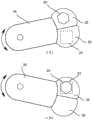
图2示出了产生花效果的照明装置的光学引擎的主要部件的实施例的布局;Figure 2 shows the layout of an embodiment of the main components of an optical engine of a lighting device producing a flower effect;
图3示出了图2中示出的光学引擎的主要部件和布局的一些所述实施例的更多细节;Figure 3 shows further details of some of the described embodiments of the main components and layout of the optical engine shown in Figure 2;
图4示出了用于光导组件的附加支承结构的实施例;Figure 4 shows an embodiment of an additional support structure for the light guide assembly;
图5示出了没有任何支承结构的光导的实施例;Figure 5 shows an embodiment of a light guide without any support structure;
图6示出了光学软化漫射器臂的实施例的细节;Figure 6 shows details of an embodiment of an optical softening diffuser arm;
图7示出了包括光导的实施例的照明装置;Figure 7 shows a lighting device comprising an embodiment of a light guide;
图8示出了具有输出透镜就位的图7;Figure 8 shows Figure 7 with the output lens in place;
图9示出了具有处于广角位置的透镜的光学系统的实施例的细节;Figure 9 shows details of an embodiment of an optical system with a lens in a wide angle position;
图10示出了具有处于窄角位置的透镜的光学系统的实施例的细节;Figure 10 shows details of an embodiment of an optical system with lenses in narrow angle positions;
图11示出了在图1中所示的照明系统中使用的完整的照明装置;以及Figure 11 shows a complete lighting device used in the lighting system shown in Figure 1; and
图12示出了光学系统的透镜的细节。Figure 12 shows details of the lenses of the optical system.
具体实施方式Detailed ways
附图中示出了本公开的优选实施例,相同的附图标记用于表示各个附图中的相同和相应的部分。Preferred embodiments of the present disclosure are illustrated in the accompanying drawings, wherein like reference numerals are used to refer to like and corresponding parts throughout the various views.
本公开一般涉及一种在染色光照明装置中提供特殊效果的方法,具体来说,涉及从具有大的有效光源和真实混合输出分布的染色光分布的照明装置提供可控照明效果的方法。The present disclosure generally relates to a method of providing special effects in a dye light lighting device, and in particular, to a method of providing controllable lighting effects from a lighting device having a large effective light source and a dye light distribution with a true mixed output distribution.
图2示出了产生花效果的照明装置的一个光学引擎120的主要部件的实施例的布局。发光模块20包括单个LED或LED阵列,其可以包括主光学器件(未示出)。发光模块20可以包含单色LED或可以包含多个管芯,每个管芯可以是相同或不同的颜色。例如,在一个实施例中,发光模块20可以包括红色、绿色、蓝色和白色LED中的每一个。在其他实施例中,发光模块20可以包括单个LED芯片或封装,而在又一些实施例中,发光模块20可以或是在单个主光学器件中或是在其主光学器件的每个封装中包括多个LED芯片或封装。在一些实施例中,这些LED管芯可以与光学透镜元件配对,作为LED发光模块的一部分。在另一实施例中,发光模块20可以包括多于四种颜色的LED。例如,可以使用七种颜色,红色、绿色、蓝色、白色、琥珀色、青色和深蓝色/紫外线LED模具各一个。Figure 2 shows the layout of an embodiment of the main components of an
来自发光模块20中的LED的光输出进入包含在保护套管24内的光导光学器件22。光导光学器件(light guide optic)22可以是利用内部反射的装置,以便收集、均质化并约束光并将光传导至出口23。光导光学器件22可以是具有反射内表面的中空管,使得照射进入口的光可以在离开出口23之前沿着管多次反射。光导光学器件22可以是方管、六角形管、七边形管、八边形管、圆形管或任何其他横截面的管。在另一个实施例中,光导光学器件22可以是由玻璃、透明塑料或其他光学透明材料构成的实心杆,其中入射光束在杆内的反射是由于杆的材料与周围空气之间的界面的“全内反射”(TIR:total internal reflection)造成的。整合杆可以是方杆、六角杆、七角杆、八角杆、圆杆或任何其他横截面的杆。光导光学器件22,无论是实心的还是中空的,并且具有任何数量的侧面,可以具有横截面形状不同的入口21和出口23。例如,方形出口21和八边形出口23。另外,光导光学器件22可以具有渐缩的侧面,使得入口孔小于出口孔。这样的结构的优点是在出口23处离开光导光学器件22的光的发散角将小于进入光导光学器件22的光的发散角。较小的发散角与较大的孔径的组合用于保存系统的光学扩展量。因此,锥形的光导光学器件22可以提供与聚光光学系统类似的功能。在本公开的优选的实施例中,光导光学器件22具有方形入口21和方形出口23。对于期望的联想到花的效果,有利的是使用具有相对侧的形状并且沿光导光学器件22的长度具有相同形状的横截面。The light output from the LEDs in
光导光学器件22可以具有纵横比,其长度远大于其直径。长度与直径之间的比率越大,所得混合和均质化越好。光导光学器件22可以封闭在管或保护套管24中,该管和保护套管24提供机械保护以防止损坏、刮擦和灰尘。在优选实施例中,光导光学器件22具有这样的长度,以便准直和引导但有意地提供来自发光模块20上的各个LED的光的不完全均质化。这种不完全均质化可以有利地用于光学系统的其余部分。类似的,光导22的出口被抛光,而不是被漫射或纹理化,以保持输入光束的不完全均质化。在一个实施例中,光束被小于50%地均质化,使得来自单独LED的各个光束或颜色仍然清晰可见。The
光导光学器件22在其保护套筒24内被安装成使得它可以沿其长的光轴通过由轴承66支承的电动机(未示出)和齿轮32自由旋转。旋转的光导22将使来自出口23的发射光束也围绕系统的光轴旋转。事实上,由于光导光学器件22的输入端口穿过固定发光模块20中的LED阵列的旋转和旋转光导内的全内反射的作用,光束的移动和旋转将是复杂的。因此,离开光导光学器件22的光束将呈现复杂且动态的移动光束图案。光导光学器件22可以在操作者的控制下沿任一方向和以任何速度旋转。The
在本公开的基本形式中,来自光导光学器件22的出口23的光将被引向并穿过透镜40,用于进一步控制发射光束的角度。透镜40可以沿着由线41所示系统的光轴的方向43朝向/远离光导光学器件22移动。在透镜40在其与光导光学器件22的出口23最远间隔的位置,发射的光束将具有窄的光束角。在透镜40在其与光导光学器件22的出口23最近间隔的位置,发射的光束将具有宽的光束角。透镜40相对于光导光学器件22的出口23的中间位置将提供中间光束角。透镜40可以有利地配置为消色差透镜,以最小化发射的光束的色差。这里示出的系统利用单个透镜元件作为透镜40来提供输出光束控制。然而,本公开不限于此,并且其他实施例可以包含不同数量和类型的透镜或本领域公知的其他光学系统。特别地,其他实施例可以利用透镜40包括多个元件的系统。在另外的实施例中,透镜40可以包括多个光学透镜元件,这些光学透镜元件彼此的关系不固定,并且可以改变。透镜40的元件可以是弯月形透镜、平凸透镜、双凸透镜、全息透镜、非球面透镜或本领域公知的其他透镜。透镜40的元件可以由玻璃、透明塑料或本领域已知的其他光学透明材料构成。In the basic form of the disclosure, light from the
在一个优选实施例中,透镜40包括通过使用非球面或其他方式构造的单个元件,以呈现消色差特性,使得光束中的颜色保持均质化并且不会对光束产生令人讨厌的彩色边纹。In a preferred embodiment, the
利用所描述的布局,来自照明装置的效果将是由光导光学器件22内的发光模块20中的来自LED的各个光束的反射所产生的多个光束的复杂图案的效果。由于没有提供漫射或其他均质化,这些光束将通过包括透镜40的投影透镜系统保持不同的颜色和图案。当光导光学器件22旋转时,并且透镜40朝向/远离光导光学器件22的出口23移动时,效果将是随着透镜移动而展开/关闭的花朵或光束的铺展图案。With the described layout, the effect from the lighting device will be the effect of a complex pattern of multiple light beams created by reflection of individual light beams from the LEDs in the
为了将照明装置改变为染色光模式而不是光束效果,漫射器臂26可以在靠近光导光学器件22的出口23的光束上摆动。漫射器臂26可以包含多个漫射器,每个漫射器可以具有不同的漫射特性。在所示实施例中,漫射器臂26装配有第一漫射器28和第二漫射器30,然而,其他实施例可具有不同数量的漫射器。在操作中,漫射器臂26旋转,使得漫射器28或30中的一个定位在光导光学器件22的出口23附近,用于在从出口23发射的光束进入光学系统的其余部分之前使从出口23发射的光束漫射和均质化。漫射器用于将光束合并成单个均质化光束并增加光束的漫射。漫射器28或30的不同强度或特性可以提供窄的或宽的均质化的光束而没有花效果,或者对于较低功率的漫射器,可以提供花效果的软化。在这种操作模式中,透镜40将继续控制均质化光束的整体尺寸。In order to change the lighting arrangement to a dye light mode rather than a beam effect, the
图3示出了图2中所示的光学引擎120的主要组件和布局的一些实施例的更多细节。更具体地,在图3中,可以更清楚地看到光导光学器件22的出口23和用于使漫射器28和30移动穿过该出口的装置。子图3a示出了光束花效果模式中的系统,其中漫射器臂26旋转使得漫射器28和漫射器30都不跨越出口23定位。在这个位置,未漫射的光束呈现花效果。FIG. 3 shows more details of some embodiments of the main components and layout of the
电动机33提供用于使光导光学器件22旋转通过齿轮32的运动,并且电动机35为漫射器臂26提供运动。本领域公知的类似电动机和驱动系统为透镜40提供沿着照明装置光轴的运动。电动机33和35可以是步进电动机、伺服电动机、线性致动器、螺线管、DC电动机或本领域公知的其他机构。在所示的实施例中,电动机33和35通过齿轮系统操作。例如,电动机33驱动齿轮32。还可以想到用于致动所需运动的如本领域所公知的其他机构。
子图3b示出了处于染色光模式的系统,其中漫射器臂26旋转使得第二漫射器30横跨出口23定位。在该位置,光束被第二漫射器30漫射并呈现均质化的光束而没有花效果。Sub-figure 3b shows the system in dyed light mode, where the
图4示出了包括其支承结构的光导组件。子图4a、图4b、图4c和图4d示出了从完全分解(4a)到完全组装(4d)的组件以帮助理解结构。具有出口23的光导光学器件22插入保护套筒24中。保护套筒24具有轴承支承表面64和68作为其结构的一部分。轴承支承表面64和68分别与轴承66和70接合。这允许保护套筒24(并且因此光导光学器件22)在轴承66和70内旋转。齿轮62也连接至保护套筒24,齿轮62与图3中所示的齿轮32啮合,齿轮32由电动机33驱动。由保护套筒24、光导光学器件22、轴承66和70以及齿轮62形成的组件被支承在支架72内,使得(如图4d所示)光导光学器件22从支架72的基部突出并与发光模块20对准。该组件还用于保持光导光学器件22的入口21与发光模块20之间的小间隔,使得来自发光模块20和光导光学器件22的光传输最大化但两个表面不接触。Figure 4 shows the light guide assembly including its support structure. Sub-figures 4a, 4b, 4c and 4d show the assembly from fully disassembled (4a) to fully assembled (4d) to help understand the structure. The
可以设想,如图4所示的光导组件可以在单个照明装置内多个或成阵列使用。例如,可以使用旋转光导组件阵列,其中每个光导定位在其自身的发光模块上方。在这些实施例中,单个电动机可以驱动多个光驱动组件的旋转。It is contemplated that the light guide assemblies shown in Figure 4 may be used in multiples or arrays within a single lighting device. For example, an array of rotating light guide assemblies can be used, where each light guide is positioned over its own light emitting module. In these embodiments, a single motor can drive the rotation of multiple light drive assemblies.
图5示出了没有其支承结构的光导光学器件22的实施例。光导光学器件22包含入口21和出口23。在所示的实施例中,光导光学器件22是锥形的并且具有方形入口21和方形出口23。Figure 5 shows an embodiment of the
图6示出了光学软化漫射器臂26的实施例的细节。漫射器臂26在图6中示出为处于两个位置。在位置A,漫射器臂26被定位成使得第二漫射器30横跨出口23(在漫射器下方以虚线示出)。还示出了漫射器臂26的可选特征。第一漫射器28包括掩模29,其用于将光约束成掩模形状。掩模29是具有中心开口的不透明掩模,在这种情况下,该开口具有六边形形状。掩模29有助于将投射光束约束成更圆的非方形形状。掩模29可以是任何形状,而不仅仅是本文所示的六边形,包括但不限于圆形、六边形或八边形。FIG. 6 shows details of an embodiment of an optical
在位置B,漫射器臂26定位成使得包括掩模29的第一漫射器28横跨出口23(在漫射器下方以虚线示出)。漫射器28和30可以提供不同量或类型的漫射,从而在输出中产生不同的光束漫射。漫射器28和30可以是图案化的或模制的玻璃或塑料,或者可以是全息漫射器或本领域公知的其他漫射器类型。尽管这里示出了两个不同的漫射器28和30,但是本公开并不局限于此,并且可以固定和选择任何数量的漫射器或均化器作为漫射器臂26的一部分。In position B, the
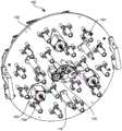
图7示出了具有特殊效果照明装置的染色光的替代实施例的光学支承板100的布局,该照明装置采用光学引擎模块阵列。光学支承板100包括安装板102,多个LED光源安装在安装板102上,每个LED光源具有它们自己相关的光导104。在所示实施例中,使用了19个LED光源,布置成单个中央LED光源以及围绕其的6个和12个LED光源的两个同心环,但是实际上可以设想使用任何数量的LED光源。例如,可以省略外环,提供具有7个LED光源的系统,或者可以添加额外的一个环或多个环,从而提供更多数量的LED光源。在此,19个LED光源和光导104被布置在同心环中,但也可以以其他配置布置。一些百分比的LED光源和光导104可以配备光学软化漫射器臂26系统,以提供如图2至图6所示的模块。在所示的实施例中,单个中央LED光源与系统一起配备为光学软化漫射器系统(光学引擎)120。在实践中,任何数量的光导104可以配备有光学软化漫射器系统120。然而,在优选的实施例中,使用由具有“完全均质化”或至少更均质化的光导104的LED光源包围的单个中心安装光学引擎120提供了效果和标准染色光运用的良好组合。没有配备光学软化漫射器系统120的光导104可以具有图案化、纹理化或漫射的出口,或者可以具有类似于漫射器28和30的漫射滤光器,其永久地连接或构造为光导出口的一部分或者光导可以另外设计成“完全均质化”光,使得这些光导总是产生平滑、均质的光输出。相反,可以远程控制装配有光学软化漫射器系统120的光导104,以通过在光束上插入或移除漫射器28和30而产生所需的光滑均质输出或边缘更硬的花效果。Figure 7 shows the layout of an
图8示出了具有光学支承板100的图7中所示的系统,此时装配有输出透镜模块130。输出透镜模块130包含透镜阵列,其数量与图7中所示的LED光源和相关光导相同。透镜可以具有不同的轮廓形状,以便装配成美学上令人愉悦的设计,并且还最小化透镜之间浪费的任何空间。透镜之间的这种间隙可能降低系统的输出,和在观察照明装置时在光输出中产生不希望的可见间隙。在此介绍的设计类似于蜘蛛网的设计,提供功能目的和美学吸引力。尽管具有不同形状,但透镜可具有基本相同的光学特性。例如,中心透镜132可以与边缘透镜134具有相同的光学强度并提供相同的光学效果。在其他实施例中,与装配有光学软化漫射器系统120的LED光源相关联的透镜(例如与图7中的所述中央LED光源相关联的中心透镜132),可以具有与和标准光导104相关联的边缘透镜134相同或不同的光学性质。FIG. 8 shows the system shown in FIG. 7 with the
图9和图10示出了如图8所示的系统的侧视图。在图9中,包含透镜阵列134和132的输出透镜模块130靠近中心光学引擎模块上的光导104和光学软化漫射器系统120定位。在示出的实施例中,仅中心光学引擎模块(光学引擎120)在中心位置具有减小的均质化类型。在其他实施例中,这种类型的模块可以放置在非中心位置。在另一实施例中,可以存在多于一种类型的光学引擎120。虽然减小的均质化模块可以包括可选择的漫射模块,使得其光可以包括在完全染色光模式中,在另一些实施例中,完全染色光模式可以通过减少的均质化光模块来实现,而不需要漫射器,而是需要在完全染色光模式期间调暗以使这些光模块变暗的系统。当用户选择完全染色模式时,该调光可以在操作中自动连接,或者在其他实施例中,可以是手动的。在另一实施例中,所有模块都具有减小的均质化类型,并且它们都具有可选择的漫射模块。在一些实施例中,各个光学引擎模块是单独控制的,而在其他实施例中,模块是成组控制的。这些组可以在阵列中具有相似或类似的几何位置,例如外圈,内圈,等等。如果这样配备,则这些控件可以包括颜色强度漫射标志,图像倍增器,并且如果机械配置为可独立控制,则这些控制可以包括变焦透镜(未在图中示出)。9 and 10 show side views of the system shown in FIG. 8 . In Figure 9,
在图9中透镜134和132的输出位置,光输出将处于更宽的角度。在图10中,输出透镜模块130已经沿方向136远离光导104和光学软化漫射器系统120移动。在该位置,透镜134和132的输出将是窄角。透镜模块130在图9和图10中所示的那些位置中间的位置将产生中间光束角。当透镜模块移动时,将存在从光导104发射的光束的连续可变光束角度或变焦。At the output positions of
如果光学漫射器28和30没有定位穿过在光学引擎120中的光束,则当透镜处于其远处的窄角度位置时,透镜可以聚焦在LED上,并且光导中的多个内部反射光学地倍增芯片形状,从而产生鲜明的花效果。如果透镜移动到近处的广角位置,即使没有漫射器28和30就位,光学引擎120也将产生更平滑的染色型光束,具有不太明显的花效果。在任一种情况下,在漫射器28或30就位的情况下,光学引擎120中的系统将产生平滑的均质化效果,而没有花效果。If the
在所示的实施例中,输出透镜模块130的运动由作用在导螺杆108上的电动机106产生。尽管这里示出了导螺杆系统,但是本公开不限于此,并且可以设想移动透镜的其他方法,例如带系统、线性致动器、齿条和小齿轮,以及本领域公知的其他方法。输出透镜模块130由引导件110支承,使得运动被约束为沿着照明装置的光轴来回。In the embodiment shown, the motion of the
在所示的实施例中,整个透镜阵列134和132作为单个模块一起移动。然而,在另一实施例中,各个透镜或透镜组可以具有它们自己的电动机驱动系统并且能够沿光轴独立移动。特别地,与配备有光学软化漫射器系统120(例如图7中的中央光学引擎模块)的LED光源相关联的任何透镜都可以与输出透镜模块130一起移动,可以配备独立于输出透镜模块130的独立电动机控制器,或者可以静态具有固定的光束角度。In the embodiment shown, the
输出透镜模块130中的透镜132和134的设计使得当从光导104发射的来自每个光束的各个均质化光束离开输出透镜模块130后被约束以进一步重叠并混合,提供具有染色光分布的平滑连续光束,其具有大的有效光源(包括总输出透镜模块130)和真实的混合输出分布。
图11示出了可以在诸如图1中所示的照明系统中使用的完整自动照明装置150。透镜阵列130在自动照明装置150的外表面上可见。FIG. 11 shows a complete
图12示出了可以在所述系统中使用的输出透镜134或132的另一实施例。如前所述,这种透镜的优点是在其行为中是消色的。换句话说,它们应该尽可能少地在不同颜色的光线上产生光学效果,以避免在光束边缘产生令人讨厌的彩色边缘。在优选的实施例中,边缘透镜134包括通过使用非球面或其他方式构造的单个元件,以呈现消色差特性。在图12所示的实施例中,边缘透镜134不具有光滑表面,而是在透镜的一个或多个表面上存在微结构。一个或多个透镜表面覆盖有类似于高尔夫球上的小型工程凹陷。为了便于说明,这里示出的凹陷140比实际上更大。在一个实施例中,凹陷140的直径可以是0.3毫米(mm)-0.4毫米,深度仅为0.0001毫米。这些凹陷140,以及非球面透镜表面的使用可以用在边缘透镜134的一侧或两侧上,以便提供透镜的消色差操作。Figure 12 shows another embodiment of an
在照明装置的操作中,馈送光导104和光软化漫射系统120的LED光源可以单独地或共同地控制颜色和强度,以根据需要提供协调的染色光或效果单元。尤其是,可以控制配备有光学软化漫射器系统120的任何LED光源,使得它们或者产生上述动态花效果,或者产生平滑的染色光束以匹配标准光导104。操作者可以选择组合或混合这些效果以获得期望的结果。In operation of the lighting device, the LED light sources feeding the
虽然已经关于有限数量的实施例描述了本公开,但是受益于本公开的本领域技术人员将理解,可以设计出不脱离本文公开的本公开的范围的其他实施例。已经详细描述了本公开,应当理解,在不脱离本公开的精神和范围的情况下,可以对其进行各种改变,替换和更改。While the present disclosure has been described with respect to a limited number of embodiments, those skilled in the art having the benefit of this disclosure will appreciate that other embodiments can be devised without departing from the scope of the disclosure disclosed herein. The present disclosure has been described in detail, it should be understood that various changes, substitutions and alterations can be made hereto without departing from the spirit and scope of the disclosure.
Claims (11)
Translated fromChineseApplications Claiming Priority (3)
| Application Number | Priority Date | Filing Date | Title |
|---|---|---|---|
| US15/089,116 | 2016-04-01 | ||
| US15/089,116US10132992B2 (en) | 2016-03-20 | 2016-04-01 | Special flower effects beam and washlight luminaire |
| PCT/US2017/025658WO2017173429A1 (en) | 2016-04-01 | 2017-04-01 | A special flower effects beam and washlight luminaire |
Publications (2)
| Publication Number | Publication Date |
|---|---|
| CN109312902A CN109312902A (en) | 2019-02-05 |
| CN109312902Btrue CN109312902B (en) | 2020-10-20 |
Family
ID=59227804
Family Applications (1)
| Application Number | Title | Priority Date | Filing Date |
|---|---|---|---|
| CN201780034567.2AActiveCN109312902B (en) | 2016-04-01 | 2017-04-01 | Dyeing light illuminating device with special effect function |
Country Status (3)
| Country | Link |
|---|---|
| EP (1) | EP3436740B1 (en) |
| CN (1) | CN109312902B (en) |
| WO (1) | WO2017173429A1 (en) |
Families Citing this family (2)
| Publication number | Priority date | Publication date | Assignee | Title |
|---|---|---|---|---|
| DE102020134279A1 (en)* | 2020-12-18 | 2022-06-23 | Bartenbach Holding Gmbh | zoom illuminator |
| CN217109290U (en)* | 2022-03-31 | 2022-08-02 | 广州市浩洋电子股份有限公司 | Stage lamp with defogging device |
Citations (8)
| Publication number | Priority date | Publication date | Assignee | Title |
|---|---|---|---|---|
| JP2004297058A (en)* | 2003-03-11 | 2004-10-21 | Semiconductor Energy Lab Co Ltd | Beam homogenizer, laser irradiating device, and method of manufacturing semiconductor device |
| EP2177816A2 (en)* | 2008-10-20 | 2010-04-21 | ROBE lighting s.r.o. | A ligth collection system for an led luminaire |
| WO2010113100A1 (en)* | 2009-03-31 | 2010-10-07 | Koninklijke Philips Electronics N.V. | Led collimation optics module and luminaire using same |
| CN102095086A (en)* | 2009-12-11 | 2011-06-15 | 李金宗 | Light homogenizer and application of optical fiber panel |
| CN102859269A (en)* | 2010-04-23 | 2013-01-02 | 马丁专业公司 | Background light effects led light fixture with light guided second light sources |
| WO2014031641A2 (en)* | 2012-08-20 | 2014-02-27 | Robe Lighting, Inc. | Luminaire with articulated elongated light beam homogenizer |
| WO2015051034A3 (en)* | 2013-10-01 | 2015-06-25 | Robe Lighting, Inc. | Multiple color homogenization system for an led luminaire |
| WO2015138483A2 (en)* | 2014-03-10 | 2015-09-17 | Robe Lighting, Inc. | Optical system for an led luminaire |
Family Cites Families (2)
| Publication number | Priority date | Publication date | Assignee | Title |
|---|---|---|---|---|
| CA2487853A1 (en)* | 2002-10-09 | 2004-04-22 | Matsushita Electric Industrial Co., Ltd. | Illuminator and projection image display employing it |
| ITMI20131385A1 (en)* | 2013-08-12 | 2015-02-13 | Clay Paky Spa | SPOTLIGHT HEADLAMP, IN PARTICULAR SPOTLIGHT WITH MULTISORGENT STAGE |
- 2017
- 2017-04-01CNCN201780034567.2Apatent/CN109312902B/enactiveActive
- 2017-04-01EPEP17733564.3Apatent/EP3436740B1/enactiveActive
- 2017-04-01WOPCT/US2017/025658patent/WO2017173429A1/ennot_activeCeased
Patent Citations (8)
| Publication number | Priority date | Publication date | Assignee | Title |
|---|---|---|---|---|
| JP2004297058A (en)* | 2003-03-11 | 2004-10-21 | Semiconductor Energy Lab Co Ltd | Beam homogenizer, laser irradiating device, and method of manufacturing semiconductor device |
| EP2177816A2 (en)* | 2008-10-20 | 2010-04-21 | ROBE lighting s.r.o. | A ligth collection system for an led luminaire |
| WO2010113100A1 (en)* | 2009-03-31 | 2010-10-07 | Koninklijke Philips Electronics N.V. | Led collimation optics module and luminaire using same |
| CN102095086A (en)* | 2009-12-11 | 2011-06-15 | 李金宗 | Light homogenizer and application of optical fiber panel |
| CN102859269A (en)* | 2010-04-23 | 2013-01-02 | 马丁专业公司 | Background light effects led light fixture with light guided second light sources |
| WO2014031641A2 (en)* | 2012-08-20 | 2014-02-27 | Robe Lighting, Inc. | Luminaire with articulated elongated light beam homogenizer |
| WO2015051034A3 (en)* | 2013-10-01 | 2015-06-25 | Robe Lighting, Inc. | Multiple color homogenization system for an led luminaire |
| WO2015138483A2 (en)* | 2014-03-10 | 2015-09-17 | Robe Lighting, Inc. | Optical system for an led luminaire |
Also Published As
| Publication number | Publication date |
|---|---|
| WO2017173429A1 (en) | 2017-10-05 |
| EP3436740B1 (en) | 2025-05-28 |
| EP3436740A1 (en) | 2019-02-06 |
| CN109312902A (en) | 2019-02-05 |
Similar Documents
| Publication | Publication Date | Title |
|---|---|---|
| US10690842B2 (en) | Wash light luminaire with special effects capabilities | |
| EP3433534B1 (en) | A special flower effects beam and washlight luminaire | |
| EP2177816B1 (en) | A ligth collection system for an led luminaire | |
| US9995463B2 (en) | Illumination device with spinning zoom lens | |
| EP4092316A1 (en) | Led light engine with integrated color system | |
| EP3052982B1 (en) | Collimation and homogenization system for an led luminaire | |
| US20170074497A1 (en) | Luminaire with articulated leds | |
| WO2015138483A2 (en) | Optical system for an led luminaire | |
| US10408402B2 (en) | Optical system for a LED luminaire | |
| WO2015077384A1 (en) | Luminaire with articulated leds | |
| US20160298829A1 (en) | System and method for controlling light output in a led luminaire | |
| WO2015051034A2 (en) | Multiple color homogenization system for an led luminaire | |
| US20170074489A1 (en) | System and method for controlling light output in a led luminaire | |
| CN109312902B (en) | Dyeing light illuminating device with special effect function | |
| US20180313521A1 (en) | System and method for controlling output in a led luminaire | |
| EP3433535B1 (en) | System and method for controlling light output in a led luminaire | |
| WO2017165685A1 (en) | Optical system for an led luminaire | |
| WO2017165686A1 (en) | Luminaire with articulated leds |
Legal Events
| Date | Code | Title | Description |
|---|---|---|---|
| PB01 | Publication | ||
| PB01 | Publication | ||
| SE01 | Entry into force of request for substantive examination | ||
| SE01 | Entry into force of request for substantive examination | ||
| GR01 | Patent grant | ||
| GR01 | Patent grant |