CN109286977B - Anchor-free localization method based on distance information - Google Patents
Anchor-free localization method based on distance informationDownload PDFInfo
- Publication number
- CN109286977B CN109286977BCN201811181393.5ACN201811181393ACN109286977BCN 109286977 BCN109286977 BCN 109286977BCN 201811181393 ACN201811181393 ACN 201811181393ACN 109286977 BCN109286977 BCN 109286977B
- Authority
- CN
- China
- Prior art keywords
- positioning
- positioning target
- targets
- target
- distance
- Prior art date
- Legal status (The legal status is an assumption and is not a legal conclusion. Google has not performed a legal analysis and makes no representation as to the accuracy of the status listed.)
- Active
Links
Images


Classifications
- H—ELECTRICITY
- H04—ELECTRIC COMMUNICATION TECHNIQUE
- H04W—WIRELESS COMMUNICATION NETWORKS
- H04W64/00—Locating users or terminals or network equipment for network management purposes, e.g. mobility management
- H04W64/006—Locating users or terminals or network equipment for network management purposes, e.g. mobility management with additional information processing, e.g. for direction or speed determination
- G—PHYSICS
- G01—MEASURING; TESTING
- G01C—MEASURING DISTANCES, LEVELS OR BEARINGS; SURVEYING; NAVIGATION; GYROSCOPIC INSTRUMENTS; PHOTOGRAMMETRY OR VIDEOGRAMMETRY
- G01C21/00—Navigation; Navigational instruments not provided for in groups G01C1/00 - G01C19/00
- G01C21/10—Navigation; Navigational instruments not provided for in groups G01C1/00 - G01C19/00 by using measurements of speed or acceleration
- G01C21/12—Navigation; Navigational instruments not provided for in groups G01C1/00 - G01C19/00 by using measurements of speed or acceleration executed aboard the object being navigated; Dead reckoning
- G01C21/16—Navigation; Navigational instruments not provided for in groups G01C1/00 - G01C19/00 by using measurements of speed or acceleration executed aboard the object being navigated; Dead reckoning by integrating acceleration or speed, i.e. inertial navigation
- G01C21/165—Navigation; Navigational instruments not provided for in groups G01C1/00 - G01C19/00 by using measurements of speed or acceleration executed aboard the object being navigated; Dead reckoning by integrating acceleration or speed, i.e. inertial navigation combined with non-inertial navigation instruments
Landscapes
- Engineering & Computer Science (AREA)
- Radar, Positioning & Navigation (AREA)
- Remote Sensing (AREA)
- Computer Networks & Wireless Communication (AREA)
- Signal Processing (AREA)
- Automation & Control Theory (AREA)
- Physics & Mathematics (AREA)
- General Physics & Mathematics (AREA)
- Position Fixing By Use Of Radio Waves (AREA)
Abstract
Translated fromChinese
Description
Translated fromChinese技术领域technical field
本发明属于通信技术领域,特别涉及一种无锚点定位方法,可用于室内和室外在无锚点情况下的相对位置确定。The invention belongs to the technical field of communication, and in particular relates to an anchor-free positioning method, which can be used for relative position determination indoor and outdoor without anchor points.
背景技术Background technique
现有的定位技术主要有蓝牙定位技术、红外线定位技术、地磁场定位技术、Wi-Fi定位技术、超宽带UWB定位技术和惯性传感器定位技术等,其中:The existing positioning technologies mainly include Bluetooth positioning technology, infrared positioning technology, geomagnetic field positioning technology, Wi-Fi positioning technology, ultra-wideband UWB positioning technology and inertial sensor positioning technology, among which:
蓝牙定位技术,使用智能手机的蓝牙模块,需要在定位环境中部署蓝牙基站,其定位精度最高可以达到亚米级,但是这种定位方法成本高,在复杂的环境中,稳定性欠妥、受噪声干扰明显。Bluetooth positioning technology, using the Bluetooth module of the smartphone, needs to deploy a Bluetooth base station in the positioning environment, and its positioning accuracy can reach the sub-meter level, but this positioning method is expensive, in a complex environment, the stability is not good, and the Noise interference is obvious.
Wi-Fi定位技术,是利用访问接入点AP组成的WLAN网,可以完成复杂环境中的定位任务,它以节点的位置数据为依据和前提,其最高精度在1米至20米之间,由于AP通常的覆盖半径在百米以内,容易被其他信号影响,降低其定位精度,且定位功耗也较高。Wi-Fi positioning technology is a WLAN network composed of access points APs, which can complete positioning tasks in complex environments. Since the coverage radius of an AP is usually within 100 meters, it is easily affected by other signals, reducing its positioning accuracy and positioning power consumption.
红外线定位技术,是利用波长在微波和可见光之间的电磁波进行定位的技术。红外室内定位系统中的光谱中心波长范围固定,一般在830~950nm之间。其定位精度高,反应敏捷,价格低廉,但是作为室内定位它的缺点很明显,首先是光线直线传播特性,使其作用范围局限于视距范围内的定位;其次红外线光传播过程中衰减严重,这限制了其应用范围。另外其他光源产生的光线也会对红外线的正常传播产生影响。Infrared positioning technology is a technology that uses electromagnetic waves with wavelengths between microwaves and visible light for positioning. The spectral center wavelength range in the infrared indoor positioning system is fixed, generally between 830 and 950 nm. Its positioning accuracy is high, the response is quick, and the price is low, but its shortcomings as an indoor positioning are obvious. First, the linear propagation characteristics of light make its scope of action limited to positioning within the range of sight; second, the attenuation of infrared light is serious during the propagation process. This limits its scope of application. In addition, the light generated by other light sources will also affect the normal propagation of infrared rays.
地磁场定位技术,是利用室内地磁场不同的分布状态来实现室内定位。每一个室内环境都有自己独特的环境磁场,若磁场的信息足够丰富,在这样的环境磁场中移动,不同的运动路径就会得到不同的磁场观测结果,通过预先建立用于室内定位的地磁指纹库,通过地磁匹配算法解决定位问题。但这种方法对地磁场差异性要求较高,采集地磁场指纹库工作量大,在复杂的室内环境中定位精度不高。The geomagnetic field positioning technology uses the different distribution states of the indoor geomagnetic field to achieve indoor positioning. Each indoor environment has its own unique environmental magnetic field. If the information of the magnetic field is rich enough, moving in such an environmental magnetic field will result in different magnetic field observation results for different moving paths. By pre-establishing a geomagnetic fingerprint database for indoor positioning , and solve the positioning problem through the geomagnetic matching algorithm. However, this method has high requirements on the difference of the geomagnetic field, the workload of collecting the geomagnetic field fingerprint database is large, and the positioning accuracy is not high in the complex indoor environment.
基于惯性传感器的定位技术,主要分为两种:一种是传统惯性传感器定位方法,另一种是行人航迹推算方法。这两种方法均应用于智能手机,即利用智能手机携带的传感器设备,先采集运动数据,然后通过计算获取手机的位置信息。The positioning technology based on inertial sensors is mainly divided into two types: one is the traditional inertial sensor positioning method, and the other is the pedestrian track reckoning method. Both of these methods are applied to smart phones, that is, the sensor equipment carried by the smart phone is used to first collect motion data, and then obtain the location information of the mobile phone through calculation.
超宽带UWB定位技术,不依赖传统通信所必须的载波信号,使用极窄的脉冲信号,其在无遮挡的室内环境下可以达到厘米级的定位精度。超宽带实现定位系统有很多优势:1)能耗低,超宽带使用的脉冲时间很短,故它的信号功率谱的密度非常低。2)对信道的衰落不敏感。3)抗干扰性能很强,同时它也不会对同一所处环境下的其他信号产生影响。4)穿透能力强,这使得它更加适用于室内环境。5)当发射机和接收机的时钟同步匹配时,定位精度很高,可将误差控制在10cm以内。但超宽带定位技术对硬件实现性能要求较高,从而导致硬件实现的成本较高。The ultra-wideband UWB positioning technology does not rely on the carrier signal necessary for traditional communication, and uses an extremely narrow pulse signal, which can achieve centimeter-level positioning accuracy in an unobstructed indoor environment. There are many advantages to realize the positioning system of UWB: 1) Low energy consumption, and the pulse time used by UWB is very short, so its signal power spectrum density is very low. 2) Insensitive to channel fading. 3) The anti-interference performance is very strong, and it will not affect other signals in the same environment. 4) Strong penetrating ability, which makes it more suitable for indoor environment. 5) When the clocks of the transmitter and the receiver are synchronously matched, the positioning accuracy is very high, and the error can be controlled within 10cm. However, the ultra-wideband positioning technology has high requirements on the performance of hardware implementation, which leads to high cost of hardware implementation.
此外,上述现有技术多是为单个定位目标提供绝对的位置信息且定位精度较差,而没有同时能为多个定位目标提供高精度相对位置信息的定位技术。In addition, most of the above-mentioned existing technologies provide absolute position information for a single positioning target with poor positioning accuracy, but there is no positioning technology that can simultaneously provide high-precision relative position information for multiple positioning targets.
发明内容SUMMARY OF THE INVENTION
本发明的目的在于针对上述现有技术存在的不足,提出一种基于距离信息的无锚点定位方法,旨在无锚点环境下,实现对多个定位目标的高精度相对定位。The purpose of the present invention is to propose an anchor-free positioning method based on distance information, aiming at realizing the high-precision relative positioning of multiple positioning targets in an anchor-free environment.
为实现上述目的,本发明的技术方案包括如下:To achieve the above object, the technical scheme of the present invention includes the following:
1)测得各定位目标之间的距离d;1) Measure the distance d between each positioning target;
2)利用加速度传感器获得某个定位目标的行走加速度,得到此定位目标的估计行走步长l;2) Obtain the walking acceleration of a certain positioning target by using the acceleration sensor, and obtain the estimated walking step length l of this positioning target;
3)利用惯性传感器获得此定位目标此次行走相对于地理正北方向的角度α;3) Use the inertial sensor to obtain the angle α of the positioning target this time walking relative to the geographic north direction;
4)根据1)所测得各定位目标之间的距离d选取包括此定位目标在内的三个基准定位目标,确定这三个基准定位目标的相对位置,在确定这三个基准定位目标相对位置的过程中若出现此定位目标相位角方向无法确定,则利用这三个基准定位目标的坐标、行走步长l和3)中得到的相对于正北方向的角度α求得移动后的三角形面积变化关系确定此定位目标的相位角,若此次行走不能确定这个相位角,则返回2);4) According to 1) the measured distance d between each positioning target, select three reference positioning targets including this positioning target, determine the relative positions of these three reference positioning targets, and determine the relative position of these three reference positioning targets. If the phase angle direction of the positioning target cannot be determined in the process of positioning, use the coordinates of the three reference positioning targets, and the angle α relative to the true north direction obtained from the coordinates of the three reference positioning targets and the walking step lengths 1 and 3) to obtain the moved triangle. The area change relationship determines the phase angle of the positioning target. If the phase angle cannot be determined this time, return to 2);
5)任意选取某一个剩余定位目标,利用4)中确定的三个基准定位目标,根据1)得到的距离d进行三点画圆确定其相对位置;5) arbitrarily select a certain remaining positioning target, utilize the three reference positioning targets determined in 4), carry out three circles according to the distance d obtained in 1) to determine its relative position;
6)重复5)直至确定所有定位目标的相对位置。6) Repeat 5) until the relative positions of all positioning targets are determined.
本发明与现有技术相比,具有以下优点:Compared with the prior art, the present invention has the following advantages:
1、本发明由于在对定位目标的定位过程中,利用的是测距信息与传感器信息,不需要外界环境的配置,使用的均是设备自带硬件装置,实现了无锚点的相对定位,降低了环境配置问题对定位精度的影响;1. The present invention utilizes ranging information and sensor information in the positioning process of the positioning target, does not require the configuration of the external environment, and uses the hardware devices that come with the equipment, thereby realizing the relative positioning without anchor points, Reduced the impact of environmental configuration problems on positioning accuracy;
2、本发明由于提出了一种新的定位算法,融合测距信息与传感器信息,解决了在无锚点定位中的相位角无法确定的问题,可提供高精度的相对位置信息,同时适用于室内和室外场景,适用范围广泛。2. Because the present invention proposes a new positioning algorithm, which integrates ranging information and sensor information, it solves the problem that the phase angle cannot be determined in anchor-free positioning, can provide high-precision relative position information, and is suitable for Indoor and outdoor scenes, suitable for a wide range.
附图说明Description of drawings
图1是本发明的实现流程图;Fig. 1 is the realization flow chart of the present invention;
图2是本发明的测距原理图;Fig. 2 is the principle diagram of ranging of the present invention;
图3是本发明中确定三个基准定位目标相对位置的原理图;3 is a schematic diagram of determining the relative positions of three reference positioning targets in the present invention;
图4是本发明中的目标定位原理图。FIG. 4 is a schematic diagram of target positioning in the present invention.
具体实施方式Detailed ways
以下结合附图和具体实施例,对本发明作进一步详细说明。The present invention will be further described in detail below with reference to the accompanying drawings and specific embodiments.
参照图1,本发明包括以下步骤:1, the present invention includes the following steps:
步骤1,测得各定位目标之间的距离d。Step 1: Measure the distance d between each positioning target.
如图2,利用第一测距设备M与第二测距设备N进行测距的实现如下:As shown in FIG. 2 , the implementation of ranging by the first ranging device M and the second ranging device N is as follows:
1a)记录两台测距设备的消息包交互时间:1a) Record the message packet interaction time of the two ranging devices:
1a1)设定两台测距设备M和N,定义Tr1为第一测距设备M首次接收消息包到发送出Final包的间隔时间,Tr2为第二测距设备N首次接收消息包到发送出Response包的间隔时间;1a1) Set two ranging devices M and N, define Tr1 as the interval time from when the first ranging device M receives a message packet for the first time to sending the Final packet, and Tr2 is when the second ranging device N receives a message packet for the first time. The interval for sending out Response packets;
1a2)第一测距设备M发送消息包,并记录发送时间T1;1a2) the first ranging device M sends a message packet, and records the sending time T1;
1a3)第二测距设备N提前打开接收端口,接收到消息包后记录时间T2;1a3) The second ranging device N opens the receiving port in advance, and records the time T2 after receiving the message packet;
1a4)第二测距设备N在T3=T2+Tr2时刻发送Response包,发送完成后记录时间T3;1a4) The second ranging device N sends a Response packet at the moment of T3=T2+Tr2 , and records the time T3 after the sending is completed;
1a5)第一测距设备M接收Response包后记录时间T4;1a5) the first ranging device M records the time T4 after receiving the Response packet;
1a6)第一测距设备M在T5=T4+Tr1时刻发送Final包,发送完成后记录时间T5;1a6) The first ranging device M sends the Final packet at the moment of T5=T4+Tr1 , and records the time T5 after the sending is completed;
1a7)第二测距设备N收到Final包后记录时间T6;1a7) The second ranging device N records the time T6 after receiving the Final packet;
1b)根据1a)得到的时间记录计算第一测距设备M与第二测距设备N间的距离:1b) Calculate the distance between the first ranging device M and the second ranging device N according to the time record obtained in 1a):
1b1)定义第一测距设备M开始发送数据包到接收完成所用时间为TM,第二测距设备N开始发送数据包到接收完成所用时间为TN,TP为测距信号在第一测距设备M和N间传输一次所需的时间,则有:1b1) Define the time taken by the first ranging device M to start sending data packets to the completion of reception as TM , the time taken by the second ranging device N to start sending data packets to the completion of reception is TN , and TP is the ranging signal at the first The time required for one transmission between the ranging devices M and N is:
TM=T4-T1=Tr2+2TP <1>TM =T4-T1=Tr2 +2TP <1>
TN=T6-T3=Tr1+2TP <2>TN =T6-T3=Tr1 +2TP <2>
1b2)由1a4)和1a6可得,Tr1和Tr2的表达式如下:1b2) can be obtained from 1a4) and 1a6, and the expressions of Tr1 and Tr2 are as follows:
Tr1=T5-T4,Tr1 =T5-T4,
Tr2=T3-T2,Tr2 =T3-T2,
1b3)由式<1>和式<2>可解得TP,1b3) TP can be solved by formula <1> and formula <2>,

得到第一测距设备M与第二测距设备N间的距离为:The distance between the first ranging device M and the second ranging device N is obtained as:
d=TP·c, 其中c为光速。d=TP ·c, where c is the speed of light.
1b4)重复1a)和1b)得到所有定位目标之间的相距距离。1b4) Repeat 1a) and 1b) to get the distances between all positioning targets.
步骤2,获取定位目标的估计行走步长l,相对于地理正北方向的角度α。Step 2: Obtain the estimated walking step length l of the positioning target, and the angle α relative to the geographic north direction.
选取一个定位目标,利用加速度传感器获得此定位目标的加速度信息,并根据加速度信息进行步长估计,得到行走步长l,通过如下公式实现:Select a positioning target, use the acceleration sensor to obtain the acceleration information of the positioning target, and estimate the step length according to the acceleration information to obtain the walking step length l, which is realized by the following formula:
l=ka+b,l=ka+b,
其中,k为设定好的线性增长率,a为加速度传感器得到的行走加速度,b为调整步长的固定数值。Among them, k is the set linear growth rate, a is the walking acceleration obtained by the acceleration sensor, and b is a fixed value for adjusting the step size.
利用惯性传感器获得此定位目标此次行走相对于地理正北方向的角度α。The inertial sensor is used to obtain the angle α of the positioning target's current walking relative to the geographic north direction.
步骤3,确定三个基准定位目标的相对位置。Step 3: Determine the relative positions of the three reference positioning targets.
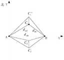
如图3,确定三个基准定位目标相对位置的实现如下:As shown in Figure 3, the implementation of determining the relative positions of the three reference positioning targets is as follows:
3a)在所有定位目标中选取包括步骤2中选定定位目标在内的三个不在同一直线上的基准定位目标,命名为第一定位目标A、第二定位目标B、第三定位目标C,其中第三定位目标C为步骤2中选定的定位目标;3a) in all positioning targets, select three reference positioning targets that are not on the same straight line including selected positioning targets in step 2, named as the first positioning target A, the second positioning target B, the third positioning target C, Wherein the third positioning target C is the positioning target selected in step 2;
测得第一定位目标A与第二定位目标B之间的距离dAB,第二定位目标B与第三定位目标C之间的距离dBC,第一定位目标A与第三定位目标C之间的距离dAC;The distance dAB between the first positioning target A and the second positioning target B, the distance dBC between the second positioning target B and the third positioning target C, and the distance between the first positioning target A and the third positioning target C are measured. distance dAC ;
取第一定位目标A为定位原点(0,0),AB射线方向为定位坐标系x轴,设定y正轴方向为正北方向,则第二定位目标B的坐标为(dAB,0);Take the first positioning target A as the positioning origin (0,0), the AB ray direction is the x-axis of the positioning coordinate system, and set the positive y-axis direction as the true north direction, then the coordinates of the second positioning target B are (dAB ,0 );
3b)计算第三定位目标C相对于第一定位目标A、第二定位目标B的方向信息为射线AB与射线AC的夹角∠A,具体求解公式如下:3b) Calculate the direction information of the third positioning target C relative to the first positioning target A and the second positioning target B as the angle ∠A between the ray AB and the ray AC, and the specific solution formula is as follows:

3c)仅利用3b)中得到的方向信息无法判断第三定位目标C与AB连线的位置关系,故此时会存在第三定位目标C相位角无法确定的问题,在此种情况下结合距离信息求出的定位目标C的相对位置坐标有两个,即第三定位目标C在AB连线正y轴方向的坐标C1,第三定位目标C在AB连线负y轴方向的坐标C2,具体的坐标求解如下:3c) The positional relationship between the third positioning target C and the line AB cannot be judged by only using the direction information obtained in 3b), so there is a problem that the phase angle of the third positioning target C cannot be determined at this time. In this case, the distance information is combined There are two relative position coordinates of the obtained positioning target C, namely the coordinate C1 of the third positioning target C in the positive y-axis direction of the AB connection line, and the coordinate C2 of the third positioning target C in the negative y-axis direction of the AB connection line. , the specific coordinates are as follows:
C1(dAC cos∠A,dAC sin∠A),C1 (dAC cos∠A,dAC sin∠A),
C2(dAC cos∠A,-dAC sin∠A);C2 (dAC cos∠A,-dAC sin∠A);
3d)利用步骤2中得到的行走步长l和第三定位目标C此次行走相对于地理正北方向的角度α,求得行走后的第三定位目标C的相对位置坐标有两个,即第三定位目标C行走步长l后在AB连线正y轴方向的坐标C'1,第三定位目标C行走步长l后在AB连线负y轴方向的坐标C'2;3d) Utilize the walking step length 1 obtained in step 2 and the angle α of the third positioning target C to walk this time with respect to the geographic north direction, to obtain two relative position coordinates of the third positioning target C after walking, that is, The third positioning target C is the coordinate C'1 in the positive y-axis direction of the AB connection line after the step length 1, and the third positioning target C is the coordinate C'2 in the negative y-axis direction of the AB connection line after the step length 1;
3e)分别比较三角形ABC1与三角形ABC'1的面积和三角形ABC2与三角形ABC'2的面积,确定第三定位目标C的相位角:3e) Compare the area of triangle ABC1 and triangle ABC'1 and the area of triangle ABC2 and triangle ABC'2 respectively, and determine the phase angle of the third positioning target C:
若三角形ABC'1的面积大于三角形ABC1的面积,且三角形ABC'2的面积小于三角形ABC2的面积,则第三定位目标C的坐标为C1;If the area of the triangle ABC'1 is greater than the area of the triangle ABC1 , and the area of the triangle ABC'2 is smaller than the area of the triangle ABC2 , the coordinate of the third positioning target C is C1 ;
若三角形ABC'1的面积小于三角形ABC1的面积,且三角形ABC'2的面积大于三角形ABC2的面积,则第三定位目标C的坐标为C2;If the area of the triangle ABC'1 is less than the area of the triangle ABC1 , and the area of the triangle ABC'2 is greater than the area of the triangle ABC2 , the coordinate of the third positioning target C is C2 ;
否则,重复步骤2至3,直至求出C点坐标。Otherwise, repeat steps 2 to 3 until the coordinates of point C are obtained.
步骤4,确定剩余定位目标的相对位置。Step 4: Determine the relative positions of the remaining positioning targets.
4a)选取除步骤3中的三个基准定位目标A、B、C之外的某个剩余定位目标命名为普通定位目标D,4a) select some remaining positioning targets except the three benchmark positioning targets A, B, C in step 3 and name them as common positioning targets D,
按照步骤1的测距方法得到普通定位目标D到步骤3中三个基准定位目标A、B、C的距离为dAD、dBD、dCD;According to the ranging method in step 1, the distances from the ordinary positioning target D to the three reference positioning targets A, B, and C in step 3 are dAD , dBD , and dCD ;
4b)如图4,由步骤3得到第一基准定位目标A坐标(0,0)、第二基准定位目标B坐标(dAB,0)和第三基准定位目标C坐标(xC,yC),以第一基准定位目标A为圆心,以第一基准定位目标A到普通定位目标D的相距距离dAD画圆;以第二基准定位目标B为圆心,以第二基准定位目标B到普通定位目标D的相距距离dBD画圆;以第三基准定位目标C为圆心,以第三基准定位目标C到普通定位目标D的相距距离dCD画圆;由于D点同时在这三个圆上,因此D点为这三个圆的交点,且满足以下方程组:4b) As shown in Figure 4, the first reference positioning target A coordinates (0,0), the second reference positioning target B coordinates (dAB , 0) and the third reference positioning target C coordinates (xC , yC ) are obtained from step 3 ), take the first reference positioning target A as the center of the circle, and draw a circle with the distance dAD from the first reference positioning target A to the common positioning target D; Draw a circle with the distance dBD of the common positioning target D; take the third reference positioning target C as the center of the circle, and draw a circle with the distance dCD from the third reference positioning target C to the common positioning target D; on the circle, so point D is the intersection of these three circles and satisfies the following equations:

4c)求解4b)中的方程组得到D点坐标;4c) Solving the equations in 4b) to obtain the coordinates of point D;
4d)重复4a)至4c)直至确定出所有定位目标的相对位置。4d) Repeat 4a) to 4c) until the relative positions of all positioning targets are determined.
以上描述仅是本发明的一个具体实例,并未构成对本发明的任何限制,显然对于本领域的专业人员来说,在了解了本发明内容和原理后,都可能在不背离本发明原理、结构的情况下,进行形式和细节上的各种修改和改变,但是这些基于本发明思想的修正和改变仍在本发明的权利要求保护范围之内。The above description is only a specific example of the present invention, and does not constitute any limitation to the present invention. Obviously, for those skilled in the art, after understanding the content and principles of the present invention, they may not deviate from the principles and structures of the present invention. Under the circumstance of the present invention, various modifications and changes in form and details are made, but these modifications and changes based on the idea of the present invention are still within the scope of protection of the claims of the present invention.
Claims (5)


Priority Applications (1)
| Application Number | Priority Date | Filing Date | Title |
|---|---|---|---|
| CN201811181393.5ACN109286977B (en) | 2018-10-11 | 2018-10-11 | Anchor-free localization method based on distance information |
Applications Claiming Priority (1)
| Application Number | Priority Date | Filing Date | Title |
|---|---|---|---|
| CN201811181393.5ACN109286977B (en) | 2018-10-11 | 2018-10-11 | Anchor-free localization method based on distance information |
Publications (2)
| Publication Number | Publication Date |
|---|---|
| CN109286977A CN109286977A (en) | 2019-01-29 |
| CN109286977Btrue CN109286977B (en) | 2020-11-06 |
Family
ID=65176775
Family Applications (1)
| Application Number | Title | Priority Date | Filing Date |
|---|---|---|---|
| CN201811181393.5AActiveCN109286977B (en) | 2018-10-11 | 2018-10-11 | Anchor-free localization method based on distance information |
Country Status (1)
| Country | Link |
|---|---|
| CN (1) | CN109286977B (en) |
Families Citing this family (2)
| Publication number | Priority date | Publication date | Assignee | Title |
|---|---|---|---|---|
| CN112098933A (en)* | 2020-09-30 | 2020-12-18 | 张来奇 | Positioning method, device and system |
| CN112637760B (en)* | 2020-12-07 | 2022-03-11 | 西安电子科技大学 | A fast indoor non-line-of-sight positioning method based on UWB |
Citations (6)
| Publication number | Priority date | Publication date | Assignee | Title |
|---|---|---|---|---|
| CN101493517A (en)* | 2009-02-23 | 2009-07-29 | 东南大学 | Method for positioning node independent of geographic position information in sensor network |
| CN103809157A (en)* | 2014-02-26 | 2014-05-21 | 上海交通大学 | Dynamic Indoor Visible Light Two-Dimensional Positioning System and Method Based on Receiver Direction |
| CN105323794A (en)* | 2014-06-30 | 2016-02-10 | 中国移动通信集团公司 | Method and device for determining position of access point |
| CN107135483A (en)* | 2016-02-26 | 2017-09-05 | 日本电气株式会社 | Determine method, indoor orientation method and its device of relative distance variation tendency |
| TW201807430A (en)* | 2016-08-17 | 2018-03-01 | 阿里巴巴集團服務有限公司 | Method for determining change in distance, location prompting method and apparatus and system thereof |
| CN108520640A (en)* | 2018-03-23 | 2018-09-11 | 清研讯科(北京)科技有限公司 | Unmanned aerial vehicle navigation method, navigation equipment, and unmanned aerial vehicle based on ultra-wideband |
- 2018
- 2018-10-11CNCN201811181393.5Apatent/CN109286977B/enactiveActive
Patent Citations (6)
| Publication number | Priority date | Publication date | Assignee | Title |
|---|---|---|---|---|
| CN101493517A (en)* | 2009-02-23 | 2009-07-29 | 东南大学 | Method for positioning node independent of geographic position information in sensor network |
| CN103809157A (en)* | 2014-02-26 | 2014-05-21 | 上海交通大学 | Dynamic Indoor Visible Light Two-Dimensional Positioning System and Method Based on Receiver Direction |
| CN105323794A (en)* | 2014-06-30 | 2016-02-10 | 中国移动通信集团公司 | Method and device for determining position of access point |
| CN107135483A (en)* | 2016-02-26 | 2017-09-05 | 日本电气株式会社 | Determine method, indoor orientation method and its device of relative distance variation tendency |
| TW201807430A (en)* | 2016-08-17 | 2018-03-01 | 阿里巴巴集團服務有限公司 | Method for determining change in distance, location prompting method and apparatus and system thereof |
| CN108520640A (en)* | 2018-03-23 | 2018-09-11 | 清研讯科(北京)科技有限公司 | Unmanned aerial vehicle navigation method, navigation equipment, and unmanned aerial vehicle based on ultra-wideband |
Also Published As
| Publication number | Publication date |
|---|---|
| CN109286977A (en) | 2019-01-29 |
Similar Documents
| Publication | Publication Date | Title |
|---|---|---|
| Yang et al. | A novel NLOS error compensation method based IMU for UWB indoor positioning system | |
| CN104849740B (en) | Integrated satellite navigation and the indoor and outdoor seamless positioning system and method for Bluetooth technology | |
| CN109195099B (en) | An indoor positioning method based on the fusion of iBeacon and PDR | |
| CN107094319B (en) | High-precision indoor and outdoor fusion positioning system and method | |
| CN104655137B (en) | The Wi Fi received signals fingerprint location algorithms of pedestrian's flying track conjecture auxiliary | |
| CN105928518B (en) | Using the indoor pedestrian UWB/INS tight integrations navigation system and method for pseudorange and location information | |
| Xu et al. | Bluetooth, floor-plan, and microelectromechanical systems-assisted wide-area audio indoor localization system: Apply to smartphones | |
| Chen et al. | Smartphone-based indoor positioning technologies | |
| Zwirello et al. | Sensor data fusion in UWB-supported inertial navigation systems for indoor navigation | |
| CN102216734A (en) | Wireless-based positioning adjustments using a motion sensor | |
| CN106680765A (en) | INS/UWB pedestrian navigation system and method based on distributed combined filter | |
| CN103644905A (en) | Situation-related indoor positioning method and system | |
| CN104197930A (en) | Indoor positioning device and method based on inertial guidance and radio frequency identification | |
| Long et al. | Single UWB anchor aided PDR heading and step length correcting indoor localization system | |
| CN114216457A (en) | Multi-source data fusion positioning method and system based on ultra-wideband signals | |
| Si et al. | An adaptive weighted Wi-Fi FTM-based positioning method in an NLOS environment | |
| CN109286977B (en) | Anchor-free localization method based on distance information | |
| CN112261573B (en) | Relative positioning method, device and system between intelligent devices | |
| CN113884096A (en) | A system and method for indoor navigation | |
| Liu et al. | Performance comparison of uwb ieee 802.15. 4z and ieee 802.15. 4 in ranging, energy efficiency, and positioning | |
| CN203416427U (en) | Ad hoc network positioning system based on ZigBee technology | |
| CN101561487B (en) | A Method for Indoor Spatial Positioning | |
| Cao et al. | Doppler shift mitigation in acoustic positioning based on relative speed of base station for smartphones | |
| Hirotsu et al. | Lora-based localization for drones: Methodological enhancements explored through simulations and real-world experiments | |
| CN114545327A (en) | A motion state information and UWB fusion positioning method and positioning system |
Legal Events
| Date | Code | Title | Description |
|---|---|---|---|
| PB01 | Publication | ||
| PB01 | Publication | ||
| SE01 | Entry into force of request for substantive examination | ||
| SE01 | Entry into force of request for substantive examination | ||
| GR01 | Patent grant | ||
| GR01 | Patent grant |