CN109263038B - Spread powder formula 3D printer - Google Patents
Spread powder formula 3D printerDownload PDFInfo
- Publication number
- CN109263038B CN109263038BCN201810782473.XACN201810782473ACN109263038BCN 109263038 BCN109263038 BCN 109263038BCN 201810782473 ACN201810782473 ACN 201810782473ACN 109263038 BCN109263038 BCN 109263038B
- Authority
- CN
- China
- Prior art keywords
- fluid
- powder
- transmission belt
- direction transmission
- printer
- Prior art date
- Legal status (The legal status is an assumption and is not a legal conclusion. Google has not performed a legal analysis and makes no representation as to the accuracy of the status listed.)
- Active
Links
- 235000020610powder formulaNutrition0.000titleclaims2
- 239000012530fluidSubstances0.000claimsabstractdescription322
- 239000000843powderSubstances0.000claimsabstractdescription145
- 230000007480spreadingEffects0.000claimsabstractdescription91
- 239000007921spraySubstances0.000claimsabstractdescription74
- 230000000903blocking effectEffects0.000claimsabstractdescription46
- 238000007639printingMethods0.000claimsabstractdescription34
- 239000007788liquidSubstances0.000claimsabstractdescription29
- 238000005507sprayingMethods0.000claimsabstractdescription13
- 230000005540biological transmissionEffects0.000claimsdescription141
- 238000011084recoveryMethods0.000claimsdescription22
- 238000000465mouldingMethods0.000claimsdescription21
- 238000005192partitionMethods0.000claimsdescription12
- 230000000149penetrating effectEffects0.000claims1
- 238000000034methodMethods0.000abstractdescription7
- 230000008569processEffects0.000abstractdescription6
- 239000000463materialSubstances0.000description27
- 238000010586diagramMethods0.000description12
- 230000033001locomotionEffects0.000description9
- XLYOFNOQVPJJNP-UHFFFAOYSA-NwaterSubstancesOXLYOFNOQVPJJNP-UHFFFAOYSA-N0.000description5
- 238000004064recyclingMethods0.000description4
- 238000007789sealingMethods0.000description4
- 238000010168coupling processMethods0.000description3
- 238000005859coupling reactionMethods0.000description3
- 239000003292glueSubstances0.000description3
- 239000010959steelSubstances0.000description3
- 2380000101463D printingMethods0.000description2
- 229910000838Al alloyInorganic materials0.000description2
- 229910000851Alloy steelInorganic materials0.000description2
- 230000009471actionEffects0.000description2
- 230000008878couplingEffects0.000description2
- 238000012986modificationMethods0.000description2
- 230000004048modificationEffects0.000description2
- 230000003014reinforcing effectEffects0.000description2
- QNRATNLHPGXHMA-XZHTYLCXSA-N(r)-(6-ethoxyquinolin-4-yl)-[(2s,4s,5r)-5-ethyl-1-azabicyclo[2.2.2]octan-2-yl]methanol;hydrochlorideChemical compoundCl.C([C@H]([C@H](C1)CC)C2)CN1[C@@H]2[C@H](O)C1=CC=NC2=CC=C(OCC)C=C21QNRATNLHPGXHMA-XZHTYLCXSA-N0.000description1
- VYPSYNLAJGMNEJ-UHFFFAOYSA-NSilicium dioxideChemical compoundO=[Si]=OVYPSYNLAJGMNEJ-UHFFFAOYSA-N0.000description1
- 229910000831SteelInorganic materials0.000description1
- 239000011248coating agentSubstances0.000description1
- 238000000576coating methodMethods0.000description1
- 238000011161developmentMethods0.000description1
- 230000005611electricityEffects0.000description1
- 238000005516engineering processMethods0.000description1
- 238000004880explosionMethods0.000description1
- 239000007769metal materialSubstances0.000description1
- 239000004033plasticSubstances0.000description1
- 238000012545processingMethods0.000description1
- 238000005086pumpingMethods0.000description1
- 239000011435rockSubstances0.000description1
- 230000035945sensitivityEffects0.000description1
- 239000000741silica gelSubstances0.000description1
- 229910002027silica gelInorganic materials0.000description1
- 238000004088simulationMethods0.000description1
- 239000007787solidSubstances0.000description1
- 230000003068static effectEffects0.000description1
- 238000003466weldingMethods0.000description1
Images


Classifications
- B—PERFORMING OPERATIONS; TRANSPORTING
- B29—WORKING OF PLASTICS; WORKING OF SUBSTANCES IN A PLASTIC STATE IN GENERAL
- B29C—SHAPING OR JOINING OF PLASTICS; SHAPING OF MATERIAL IN A PLASTIC STATE, NOT OTHERWISE PROVIDED FOR; AFTER-TREATMENT OF THE SHAPED PRODUCTS, e.g. REPAIRING
- B29C64/00—Additive manufacturing, i.e. manufacturing of three-dimensional [3D] objects by additive deposition, additive agglomeration or additive layering, e.g. by 3D printing, stereolithography or selective laser sintering
- B29C64/10—Processes of additive manufacturing
- B29C64/165—Processes of additive manufacturing using a combination of solid and fluid materials, e.g. a powder selectively bound by a liquid binder, catalyst, inhibitor or energy absorber
- B—PERFORMING OPERATIONS; TRANSPORTING
- B29—WORKING OF PLASTICS; WORKING OF SUBSTANCES IN A PLASTIC STATE IN GENERAL
- B29C—SHAPING OR JOINING OF PLASTICS; SHAPING OF MATERIAL IN A PLASTIC STATE, NOT OTHERWISE PROVIDED FOR; AFTER-TREATMENT OF THE SHAPED PRODUCTS, e.g. REPAIRING
- B29C64/00—Additive manufacturing, i.e. manufacturing of three-dimensional [3D] objects by additive deposition, additive agglomeration or additive layering, e.g. by 3D printing, stereolithography or selective laser sintering
- B29C64/20—Apparatus for additive manufacturing; Details thereof or accessories therefor
- B29C64/205—Means for applying layers
- B29C64/214—Doctor blades
- B—PERFORMING OPERATIONS; TRANSPORTING
- B33—ADDITIVE MANUFACTURING TECHNOLOGY
- B33Y—ADDITIVE MANUFACTURING, i.e. MANUFACTURING OF THREE-DIMENSIONAL [3-D] OBJECTS BY ADDITIVE DEPOSITION, ADDITIVE AGGLOMERATION OR ADDITIVE LAYERING, e.g. BY 3-D PRINTING, STEREOLITHOGRAPHY OR SELECTIVE LASER SINTERING
- B33Y30/00—Apparatus for additive manufacturing; Details thereof or accessories therefor
Landscapes
- Chemical & Material Sciences (AREA)
- Engineering & Computer Science (AREA)
- Materials Engineering (AREA)
- Manufacturing & Machinery (AREA)
- Physics & Mathematics (AREA)
- Mechanical Engineering (AREA)
- Optics & Photonics (AREA)
Abstract
Translated fromChinese
Description
Translated fromChinese技术领域technical field
本发明涉及3D打印技术领域,尤其涉及一种铺粉式3D打印机。The invention relates to the technical field of 3D printing, in particular to a powder-spreading 3D printer.
背景技术Background technique
随着3D打印技术的快速发展,3D打印机已经可以打印如类岩石材料等多种打印材料,以满足不同领域的应用。目前,可以使用铺粉式3D打印机打印类岩石材料,以对所打印出的3D模型进行模拟实验研究。铺粉式3D打印机中喷液装置的喷液精度对所打印出的3D模型的精度具有很大影响,因此,现有技术中通常对喷液装置进行改进,以提高铺粉式3D打印机的打印精度。With the rapid development of 3D printing technology, 3D printers have been able to print a variety of printing materials such as rock-like materials to meet applications in different fields. At present, rock-like materials can be printed by powder-spreading 3D printers to conduct simulation experiments on the printed 3D models. The spraying accuracy of the liquid spraying device in the powder-spreading 3D printer has a great influence on the accuracy of the printed 3D model. Therefore, the liquid spraying device is usually improved in the prior art to improve the printing of the powder-spreading 3D printer. precision.
现有技术中,铺粉式3D打印机的喷液装置包括喷头、流体输送管、泵和流体桶,喷头中形成有过流通道,过流通道具有入口和出口;泵的入口端与流体桶相连,泵的出口端与流体输送管的第一端相连,流体输送管的第二端与入口相连。当喷液装置进行喷液时,泵将流体桶中的流体泵入流体输送管的第一端,然后经流体输送管的第二端流入入口后进入过流通道,最后经出口喷出流体,流体被喷至待打印材料上,以实现3D打印产品中相邻打印层之间的紧密粘接;当不需要泵入流体时,关闭泵,停止向流体输送管中泵入流体。In the prior art, the liquid spray device of the powder-spreading 3D printer includes a spray head, a fluid delivery pipe, a pump and a fluid bucket. An overflow channel is formed in the spray head, and the overflow channel has an inlet and an outlet; the inlet end of the pump is connected to the fluid bucket. , the outlet end of the pump is connected with the first end of the fluid delivery pipe, and the second end of the fluid delivery pipe is connected with the inlet. When the liquid spraying device sprays liquid, the pump pumps the fluid in the fluid barrel into the first end of the fluid delivery pipe, then flows into the inlet through the second end of the fluid delivery pipe, and then enters the overflow channel, and finally ejects the fluid through the outlet. The fluid is sprayed onto the material to be printed to achieve tight bonding between adjacent printed layers in the 3D printed product; when the fluid does not need to be pumped, turn off the pump and stop pumping fluid into the fluid delivery pipe.
现有喷液装置中,当关闭泵后,泵不再向流体输送管中泵入流体,但是,流体输送管和喷头内还遗留有流体,流体输送管中的流体会由于惯性的作用进入喷头的入口,使得过流通道中因积聚大量的流体而从喷头喷出至待打印材料上,导致所打印出的3D模型的精度较低。In the existing liquid spray device, when the pump is turned off, the pump no longer pumps fluid into the fluid delivery pipe, but there is still fluid left in the fluid delivery pipe and the nozzle, and the fluid in the fluid delivery pipe will enter the nozzle due to inertia. , so that a large amount of fluid is accumulated in the overflow channel and ejected from the nozzle to the material to be printed, resulting in a low precision of the printed 3D model.
发明内容SUMMARY OF THE INVENTION
本申请提供一种铺粉式3D打印机,以解决现有技术中铺粉式3D打印机打印类岩石等材料时精度较低的问题。The present application provides a powder-spreading 3D printer to solve the problem of low precision in the prior art when the powder-spreading 3D printer prints materials such as rocks.
一种铺粉式3D打印机,包括:打印机主体及喷液装置,所述喷液装置包括流体桶、喷头架和喷头,所述喷头架滑动安装在所述打印机主体上,所述喷头安装在所述喷头架上,所述喷头中形成有过流通道,所述过流通道具有入口和出口,所述入口与所述流体桶连接,所述出口处安装有喷嘴;所述过流通道中活动设置有阻挡件,所述阻挡件相对于所述过流通道运动至第一目标位置时将所述入口与出口导通,所述阻挡件相对于所述过流通道运动至第二目标位置时将所述入口与出口断开;所述阻挡件背离所述入口的一侧设置有弹性件,所述弹性件用于抵推所述阻挡件,以使所述阻挡件由第一目标位置运动至第二目标位置。A powder-spreading 3D printer includes: a printer main body and a liquid spray device, the liquid spray device includes a fluid bucket, a nozzle frame and a nozzle, the nozzle frame is slidably installed on the printer main body, and the nozzle is installed on the On the sprinkler head frame, an overflow channel is formed in the sprinkler head, the overflow channel has an inlet and an outlet, the inlet is connected with the fluid bucket, and a nozzle is installed at the outlet; the overflow channel is movably arranged There is a blocking member, which conducts the inlet and the outlet when the blocking member moves to the first target position relative to the flow passage, and connects the blocking member to the second target position when the blocking member moves relative to the flow passage to the second target position. The inlet is disconnected from the outlet; an elastic member is provided on the side of the blocking member away from the inlet, and the elastic member is used to push the blocking member, so as to make the blocking member move from the first target position to second target location.
进一步地,所述喷液装置还包括:第一流体输送管、第二流体输送管及第三流体输送管,所述第一流体输送管与所述喷头连接,所述第三流体输送管与所述流体桶连接,所述第二流体输送管的两端分别与所述第一流体输送管、第三流体输送管铰接且连通,以使所述喷头能够在所述打印机主体上滑动。Further, the liquid spraying device further includes: a first fluid conveying pipe, a second fluid conveying pipe and a third fluid conveying pipe, the first fluid conveying pipe is connected to the spray head, and the third fluid conveying pipe is connected to the spray head. The fluid bucket is connected, and both ends of the second fluid conveying pipe are hinged and communicated with the first fluid conveying pipe and the third fluid conveying pipe respectively, so that the spray head can slide on the printer body.
进一步地,所述第二流体输送管通过旋转接头与所述第一流体输送管铰接;所述旋转接头包括固定轴,所述固定轴的内部设有内部空腔,所述固定轴上均匀设置有多个与所述内部空腔连通的导流孔;所述固定轴上可转动地套设有两个滑套,其中一个滑套与所述第二流体输送管连通,另一个滑套与所述第一流体输送管连通;所述滑套上开设有滑套孔,所述第一流体输送管、第二流体输送管中的一个安装在所述滑套孔中,且在所述滑套转动至所述滑套孔与固定轴上的至少一个导流孔连通时,所述滑套与所述固定轴连通。Further, the second fluid delivery pipe is hinged with the first fluid delivery pipe through a rotary joint; the rotary joint includes a fixed shaft, the interior of the fixed shaft is provided with an internal cavity, and the fixed shaft is evenly arranged There are a plurality of guide holes communicating with the inner cavity; two sliding sleeves are rotatably sleeved on the fixed shaft, one of the sliding sleeves is communicated with the second fluid conveying pipe, and the other sliding sleeve is connected to the second fluid conveying pipe. The first fluid conveying pipe is connected; the sliding sleeve is provided with a sliding sleeve hole, and one of the first fluid conveying pipe and the second fluid conveying pipe is installed in the sliding sleeve hole, and is in the sliding sleeve. When the sleeve is rotated until the sliding sleeve hole communicates with at least one guide hole on the fixed shaft, the sliding sleeve communicates with the fixed shaft.
进一步地,所述第三流体输送管与所述流体桶之间有泵,以为所述流体桶中的流体向所述第三流体输送管流动提供动力;所述第三流体输送管中设置有换向阀,所述换向阀连接有安全阀,所述安全阀与所述流体桶连接,所述安全阀用于将所述第三流体输送管中的回流流体引入所述流体桶。Further, there is a pump between the third fluid conveying pipe and the fluid bucket to provide power for the fluid in the fluid bucket to flow to the third fluid conveying pipe; the third fluid conveying pipe is provided with a pump. A reversing valve, the reversing valve is connected with a safety valve, the safety valve is connected with the fluid bucket, and the safety valve is used for introducing the return fluid in the third fluid conveying pipe into the fluid bucket.
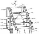
进一步地,所述打印机主体包括:支架和动力组件,所述动力组件包括第一Y方向传动带、第二Y方向传动带、X方向传动带、第一驱动件和第二驱动件;所述第一Y方向传动带和所述第二Y方向传动带平行安装在所述支架上;所述第一Y方向传动带包括相对的第一端和第二端,所述第二Y方向传动带包括相对的第三端和第四端;所述第一端与所述第三端之间通过第一旋转轴连接,且所述第一旋转轴与所述第一驱动件连接,所述第二端与所述第四端之间通过第二旋转轴连接;所述X方向传动带的两端分别安装在所述第一Y方向传动带和第二Y方向传动带上,所述喷头架搭设在所述X方向传动带上,以使所述X方向传动带能够带动所述喷头架在Y方向移动;所述第二驱动件驱动所述X方向传动带运动,以使所述X方向传动带在X方向运动。Further, the printer body includes: a bracket and a power assembly, the power assembly includes a first Y-direction transmission belt, a second Y-direction transmission belt, an X-direction transmission belt, a first driving member and a second driving member; the first Y direction transmission belt The direction transmission belt and the second Y-direction transmission belt are mounted on the bracket in parallel; the first Y-direction transmission belt includes opposite first and second ends, and the second Y-direction transmission belt includes opposite third ends and the fourth end; the first end and the third end are connected by a first rotating shaft, and the first rotating shaft is connected with the first driving member, and the second end is connected with the fourth The ends are connected by a second rotating shaft; the two ends of the X-direction transmission belt are respectively installed on the first Y-direction transmission belt and the second Y-direction transmission belt, and the nozzle frame is erected on the X-direction transmission belt to The X-direction transmission belt can drive the nozzle frame to move in the Y-direction; the second driving member drives the X-direction transmission belt to move, so that the X-direction transmission belt moves in the X-direction.
进一步地,所述支架包括四个支撑杆,四个所述支撑杆的上端都具有可伸缩的气缸,其两个气缸与所述第一旋转轴连接,另外两个气缸与所述第二旋转轴相连,以通过所述气缸带动所述第一Y方向传动带和第二Y方向传动带上下运动。Further, the bracket includes four support rods, and the upper ends of the four support rods have retractable cylinders, two cylinders are connected with the first rotating shaft, and the other two cylinders are connected with the second rotating shaft. The shafts are connected to drive the first Y-direction transmission belt and the second Y-direction transmission belt to move up and down through the cylinder.
进一步地,还包括打印成型部,所述打印成型部包括外壳,所述外壳固定在所述支架上;所述外壳具有内部空间,所述内部空间中设有分隔壁,所述分隔壁将所述外壳的内部空间分割成成型腔、储粉腔,所述成型腔、储粉腔均具有下端开口;所述成型腔、储粉腔的下方分别设置有电动推杆,所述电动推杆的输出端分别穿设在相应的下端开口中,且所述电动推杆的输出端均连接有活塞板,所述活塞板分别位于所述成型腔和所述储粉腔中,以通过所述电动推杆带动所述活塞板上下运动。Further, it also includes a printing and forming part, the printing and forming part includes a casing, and the casing is fixed on the bracket; the casing has an inner space, and a partition wall is arranged in the inner space, and the partition wall separates the The inner space of the shell is divided into a forming cavity and a powder storage cavity, and the forming cavity and the powder storage cavity both have lower end openings; the lower parts of the forming cavity and the powder storage cavity are respectively provided with an electric push rod, and the electric push rod The output ends are respectively penetrated in the corresponding lower end openings, and the output ends of the electric push rods are all connected with piston plates, and the piston plates are respectively located in the molding cavity and the powder storage cavity, so as to pass the electric push rod. The push rod drives the piston plate to move up and down.
进一步地,所述外壳包括相对设置的侧壁和连接所述侧壁的端壁,所述侧壁的两端伸出所述端壁;所述打印成型部还包括回收本体,所述回收本体与伸出所述端壁的侧壁、端壁围设成上端开口的回收腔;所述回收本体可滑动地设置在所述侧壁上。Further, the housing includes oppositely arranged side walls and an end wall connecting the side walls, two ends of the side walls protrude from the end walls; the printing and forming part further includes a recovery body, and the recovery body A recovery cavity with an open upper end is enclosed with the side wall protruding from the end wall and the end wall; the recovery body is slidably arranged on the side wall.
进一步地,还包括铺粉装置,所述铺粉装置安装在所述第一Y方向传动带和第二Y方向传动带上;所述铺粉装置包括铺粉辊和刮板,所述刮板位于铺粉辊朝向所述成型腔一侧;所述刮板设有与所述铺粉辊配合的弧面,所述刮板通过所述弧面与所述铺粉辊转动配合。Further, it also includes a powder spreading device, which is installed on the first Y-direction drive belt and the second Y-direction drive belt; the powder spreading device includes a powder spreading roller and a scraper, and the scraper is located in the shop. The powder roller faces one side of the molding cavity; the scraper is provided with an arc surface that cooperates with the powder spreading roller, and the scraper is rotatably matched with the powder spreading roller through the arc surface.
进一步地,所述铺粉装置还包括固定架,所述固定架安装在所述第一Y方向传动带和第二Y方向传动带上,所述铺粉辊可转动地安装在所述固定架上,所述刮板与所述固定架固定连接;和/或,所述刮板包括沿所述铺粉辊的轴向延伸的第一固定板,所述第一固定板朝向所述铺粉辊的一侧设有第一翻折边,所述第一翻折边朝向所述铺粉辊一侧具有所述弧面,以与所述铺粉辊配合;所述第一固定板沿所述铺粉辊轴向延伸的两端固定有侧板,所述侧板向背离所述铺粉辊的一侧延伸,且所述侧板的下端面高于所述弧面。Further, the powder spreading device further includes a fixing frame, the fixing frame is installed on the first Y-direction transmission belt and the second Y-direction transmission belt, and the powder spreading roller is rotatably installed on the fixing frame, The scraper is fixedly connected with the fixing frame; and/or, the scraper includes a first fixing plate extending along the axial direction of the powder spreading roller, and the first fixing plate faces the edge of the powder spreading roller. One side is provided with a first folded edge, and the first folded edge has the arc surface on the side facing the powder spreading roller to cooperate with the powder spreading roller; the first fixing plate is along the powder spreading roller. The two axially extending ends of the powder roller are fixed with side plates, the side plates extend to the side away from the powder spreading roller, and the lower end surface of the side plates is higher than the arc surface.
本发明提供的一种铺粉式3D打印机,通过设置包括流体桶、喷头架和喷头的喷液装置,通过将喷头架滑动安装在打印机主体上,将喷头安装在喷头架上,可以实现喷头在不同位置进行喷液;通过在喷头中形成过流通道,在过流通道中设置阻挡件,以使阻挡件能够相对于过流通道运动至第一目标位置,并将入口与出口导通,同时,过流通道中安装弹性件,弹性将能够将阻挡件由第一目标位置抵推至第二目标位置,并将入口与出口断开。采用本发明铺粉式3D打印机,能够精确控制流体的流出量,实现了铺粉过程中喷液的精确性,进而提高了打印机的打印精度;同时,本发明装置在阻挡件及弹性件的作用下能够阻挡流体的流入,便于流体在过流通道的稳定输送。The present invention provides a powder-spreading 3D printer. By arranging a liquid spray device including a fluid bucket, a spray head frame and a spray head, by slidingly installing the spray head frame on the main body of the printer, and installing the spray head on the spray head frame, the spray head can be installed on the spray head frame. Spray liquid at different positions; by forming an overflow channel in the nozzle, a blocking member is arranged in the overflow channel, so that the blocking member can move to the first target position relative to the overflow channel, and the inlet and outlet are connected, and at the same time, An elastic piece is installed in the flow passage, and the elasticity can push the blocking piece from the first target position to the second target position, and disconnect the inlet and the outlet. By using the powder-spreading 3D printer of the present invention, the outflow of the fluid can be precisely controlled, the accuracy of liquid spraying during the powder-spreading process is realized, and the printing accuracy of the printer is further improved; at the same time, the device of the present invention plays the role of the blocking member and the elastic member The lower part can block the inflow of the fluid, which is convenient for the stable delivery of the fluid in the overflow channel.
附图说明Description of drawings
此处的附图被并入说明书中并构成本说明书的一部分,示出了符合本申请的实施例,并与说明书一起用于解释本申请的原理。The accompanying drawings, which are incorporated in and constitute a part of this specification, illustrate embodiments consistent with the application and together with the description serve to explain the principles of the application.
图1为本发明一实施例中铺粉式3D打印机的主视图;1 is a front view of a powder-spreading 3D printer in an embodiment of the present invention;
图2为本发明一实施例中铺粉式3D打印机的左视图;2 is a left side view of a powder-spreading 3D printer in an embodiment of the present invention;
图3为本发明一实施例中铺粉式3D打印机的俯视图;3 is a top view of a powder-spreading 3D printer according to an embodiment of the present invention;
图4为本发明一实施例中喷头架的结构示意图;4 is a schematic structural diagram of a nozzle frame in an embodiment of the present invention;
图5为本发明一实施例中喷头内部结构示意图;5 is a schematic diagram of the internal structure of a nozzle in an embodiment of the present invention;
图6为本发明一实施例中旋转接头结构示意图;6 is a schematic structural diagram of a rotary joint in an embodiment of the present invention;
图7为本发明一实施例中一旋转接头的剖视图;7 is a cross-sectional view of a rotary joint in an embodiment of the present invention;
图8为本发明一实施例中的又一旋转接头的剖视图;8 is a cross-sectional view of yet another rotary joint in an embodiment of the present invention;
图9为本发明一实施例中的再一旋转接头的剖视图;9 is a cross-sectional view of yet another rotary joint in an embodiment of the present invention;
图10为本发明一实施例中换向阀与安全阀连接示意图;10 is a schematic diagram of the connection between the reversing valve and the safety valve in an embodiment of the present invention;
图11为本发明一实施例中动力组件的结构示意图;11 is a schematic structural diagram of a power assembly in an embodiment of the present invention;
图12为本发明一实施例中打印成型部结构示意图一;FIG. 12 is a schematic diagram 1 of the structure of the printing and forming part in an embodiment of the present invention;
图13为本发明一实施例中打印成型部结构示意图二;FIG. 13 is a second structural schematic diagram of the printing and forming part in an embodiment of the present invention;
图14为本发明一实施例中电动推杆与活塞板连接示意图;14 is a schematic diagram of the connection between an electric push rod and a piston plate in an embodiment of the present invention;
图15为本发明一实施例中电动推杆的结构示意图;15 is a schematic structural diagram of an electric push rod in an embodiment of the present invention;
图16为本发明一实施例中铺粉装置与动力组件的连接示意图;16 is a schematic diagram of the connection between the powder spreading device and the power assembly in an embodiment of the present invention;
图17为本发明一实施例中铺粉装置的结构示意图;17 is a schematic structural diagram of a powder spreading device in an embodiment of the present invention;
图18为本发明一实施例中铺粉辊的结构示意图;18 is a schematic structural diagram of a powder spreading roller in an embodiment of the present invention;
图19为本发明一实施例中刮板的主视图;19 is a front view of a scraper in an embodiment of the present invention;
图20为本发明一实施例中刮板的左视图;20 is a left side view of a scraper in an embodiment of the present invention;
图21为本发明一实施例中刮板的俯视图。21 is a top view of a scraper in an embodiment of the present invention.
附图标记:Reference number:
1-铺粉式3D打印机;1- Powder 3D printer;
100-流体桶;100 - fluid bucket;
200-喷头架;210-第一安装板;220-第二安装板;221-安装板通孔;230-第三安装板;200-sprinkler frame; 210-first mounting plate; 220-second mounting plate; 221-mounting plate through hole; 230-third mounting plate;
300-喷头;310-喷嘴;320-阻挡件;330-弹性件;300-spray head; 310-nozzle; 320-blocker; 330-elastic part;
410-第一液体输送管;411-第一刚性管;412-第二刚性管;420-第二液体输送管;430-第三液体输送管;431-第三刚性管;432-第四刚性管;410-first liquid delivery pipe; 411-first rigid pipe; 412-second rigid pipe; 420-second liquid delivery pipe; 430-third liquid delivery pipe; 431-third rigid pipe; 432-fourth rigid Tube;
500-旋转接头;510-固定轴;511-导流孔;512-第一凸起;513-第一通孔;514-第二通孔;515-第二凸起;520-滑套;521-滑套孔;500 - rotary joint; 510 - fixed shaft; 511 - guide hole; 512 - first protrusion; 513 - first through hole; 514 - second through hole; 515 - second protrusion; 520 - sliding sleeve; 521 - sliding sleeve holes;
610-泵;620-换向阀;630-安全阀;621-第一口;622-第二口;623-第三口;624-第四口;640-三通;610-pump; 620-reversing valve; 630-safety valve; 621-first port; 622-second port; 623-third port; 624-fourth port; 640-tee;
710-第一Y方向传动带;720-第二Y方向传动带;730-X方向传动带;740-第一驱动件;750-第二驱动件;760-第一旋转轴;770-第二旋转轴;780-安装架;710-first Y-direction transmission belt; 720-second Y-direction transmission belt; 730-X-direction transmission belt; 740-first driving member; 750-second driving member; 760-first rotating shaft; 770-second rotating shaft; 780 - mounting bracket;
810-支撑杆;820-气缸;830-分割壁;831-侧壁;832-端壁;840-电动推杆;850-活塞板;860-联轴器;810-support rod; 820-cylinder; 830-split wall; 831-side wall; 832-end wall; 840-electric push rod; 850-piston plate; 860-coupling;
910-铺粉辊;911-转轴;920-刮板;921-第一固定板;922-第一翻折边;923-凸起;924-侧板;930-固定架;931-轴承;932-步进电机。910-powder roller; 911-rotating shaft; 920-scraper; 921-first fixing plate; 922-first turning edge; 923-protrusion; 924-side plate; 930-fixing frame; 931-bearing; 932 - Stepper motor.
通过上述附图,已示出本申请明确的实施例,后文中将有更详细的描述。这些附图和文字描述并不是为了通过任何方式限制本申请构思的范围,而是通过参考特定实施例为本领域技术人员说明本公开的概念。Specific embodiments of the present application have been shown by the above-mentioned drawings, and will be described in more detail hereinafter. These drawings and written descriptions are not intended to limit the scope of the concepts of the present application in any way, but to illustrate the concepts of the present disclosure to those skilled in the art by referring to specific embodiments.
具体实施方式Detailed ways
这里将详细地对示例性实施例进行说明,其示例表示在附图中。下面的描述涉及附图时,除非另有表示,不同附图中的相同数字表示相同或相似的要素。Exemplary embodiments will be described in detail herein, examples of which are illustrated in the accompanying drawings. Where the following description refers to the drawings, the same numerals in different drawings refer to the same or similar elements unless otherwise indicated.
下面参考图1-图5描述根据本申请一种铺粉式3D打印机。如图1-图5所示,一种铺粉式3D打印机1,包括:打印机主体及喷液装置,喷液装置包括流体桶100、喷头架200和喷头300,喷头架200滑动安装在打印机主体上,喷头300安装在喷头架200上,喷头300中形成有过流通道,过流通道具有入口和出口,入口与流体桶100连接,出口处安装有喷嘴310;过流通道中活动设置有阻挡件320,阻挡件320相对于过流通道运动至第一目标位置时将入口与出口导通,阻挡件320相对于过流通道运动至第二目标位置时将入口与出口断开;阻挡件320背离入口的一侧设置有弹性件330,弹性件330用于抵推阻挡件320,以使阻挡件320由第一目标位置运动至第二目标位置。The following describes a powder coating type 3D printer according to the present application with reference to FIGS. 1 to 5 . As shown in FIG. 1-FIG. 5, a powder-spreading
具体地,流体桶100可以选择带有内部空腔的柱体,比如横截面为圆形或矩形等,在此并不做具体限定,只要能够满足流体的盛放即可,此处的流体可以是胶液,也可以是水,具体根据实际需要进行设定。Specifically, the
喷头架200可以包括第一安装板210、第二安装板220和第三安装板230,其中,第二安装板220和第三安装板230相对设置在第一安装板210的两端,且第二安装板220和第三安装板230均向第一安装板210的下端延伸,以便于第一安装板210滑动安装在打印机主体上。其中,第一安装板210、第二安装板220及第三安装板230均可以选择矩形板。可选的,第一安装板210、第二安装板220和第三安装板230可以为一体成型,也可以是通过焊接方式进行固定连接。可选的,喷头架200可以选择45号钢,既降低了成本,又能够保证加工所需的强度、刚度要求。The showerhead frame 200 may include a first mounting plate 210, a second mounting plate 220 and a third mounting plate 230, wherein the second mounting plate 220 and the third mounting plate 230 are oppositely disposed at two ends of the first mounting plate 210, and the third mounting plate 220 and the third mounting plate 230 Both the second mounting plate 220 and the third mounting plate 230 extend toward the lower end of the first mounting plate 210, so that the first mounting plate 210 is slidably mounted on the printer body. The first mounting plate 210 , the second mounting plate 220 and the third mounting plate 230 can all be rectangular plates. Optionally, the first mounting plate 210 , the second mounting plate 220 and the third mounting plate 230 may be integrally formed, or may be fixedly connected by welding. Optionally, the nozzle frame 200 can be made of 45-gauge steel, which not only reduces the cost, but also ensures the required strength and rigidity for processing.
喷头300可以为柱体,比如横截面为矩形或圆形等。本实施例及以下实施例均以喷头300为矩形柱为例进行描述。喷头300的内部形成有过流通道,过流通道具有入口和出口,入口可以设置在喷头300的第一侧壁上,出口可以设置在与第一侧壁相连的第二侧壁上,且第二侧壁与第一安装板210平行设置。可选的,过流通道可以是L型结构,可以理解的,过流通道包括横向流道和纵向流道,横向流道的第一端为过流通道的入口,横向流道的第二端和纵向流道的第一端相连,纵向流道的第二端为过流通道的出口。其中,过流通道的横向流道和纵向流道的截面可以是圆形。可选的,过流通道的入口可以通过软管或硬管与流体桶100相连。The shower head 300 may be a cylinder, such as a rectangular or circular cross-section. This embodiment and the following embodiments are described by taking the example that the nozzle 300 is a rectangular column. The inside of the shower head 300 is formed with a flow passage, the flow passage has an inlet and an outlet, the inlet can be arranged on the first side wall of the shower head 300, the outlet can be arranged on the second side wall connected to the first side wall, and the first side wall is connected to the first side wall. The two side walls are arranged in parallel with the first mounting plate 210 . Optionally, the flow channel can be an L-shaped structure. It can be understood that the flow channel includes a lateral flow channel and a longitudinal flow channel. The first end of the lateral flow channel is the inlet of the flow channel, and the second end of the lateral flow channel It is connected with the first end of the longitudinal flow channel, and the second end of the longitudinal flow channel is the outlet of the overflow channel. Wherein, the cross-sections of the transverse flow channel and the longitudinal flow channel of the flow channel may be circular. Optionally, the inlet of the overflow channel can be connected to the
过流通道中活动设置有阻挡件320,可选的,阻挡件320可以是圆形板,且阻挡件320的外圆周与过流通道的内圆周相适配,以便于阻挡由过流通道的入口流入的流体。阻挡件320背离入口的一侧设置有弹性件330,弹性件330的一端可以固定在与入口相对的横向流道的第二端的端壁上,弹性件330的另一端与阻挡件320固定连接。其中,弹性件330可以为伸缩弹簧。A blocking member 320 is movably arranged in the flow passage. Optionally, the blocking member 320 can be a circular plate, and the outer circumference of the blocking member 320 is adapted to the inner circumference of the flow passage, so as to block the inlet of the flow passage. inflowing fluid. An elastic member 330 is provided on the side of the blocking member 320 away from the inlet. One end of the elastic member 330 can be fixed on the end wall of the second end of the transverse flow channel opposite to the inlet. The elastic member 330 may be a telescopic spring.
可选的,过流通道中横向流道的第二端与纵向流道的第一端相连处可以设有带有多个通孔的流体隔板340,流体隔板340可以为圆形板,以与纵向流道的管径相适配,本实施例中设置流体隔板340,能够避免阻挡件320因流体的压力作用而产生一定程度倾斜,使得阻挡件320能够在弹性件330的回弹力作用下抵推至第二目标位置。Optionally, a fluid partition 340 with a plurality of through holes may be provided at the connection between the second end of the transverse flow channel and the first end of the longitudinal flow channel in the flow passage, and the fluid partition 340 may be a circular plate to In accordance with the pipe diameter of the longitudinal flow channel, the fluid baffle 340 is provided in this embodiment, which can prevent the blocking member 320 from being inclined to a certain extent due to the pressure of the fluid, so that the blocking member 320 can act on the resilience of the elastic member 330 Push down to the second target position.
当流体进入过流通道的入口时,流体的压力推动阻挡件320向背离入口的一侧运动至第一目标位置,弹性件330处于收缩状态,入口与出口导通,此处的第一目标位置指的是阻挡件320被推至横向流道的第二端的流体隔板340上,且流体能够由横向流道经流体隔板340上的通孔流入纵向流道;当停止输送流体时,横向流道中的流体的压力不足以抵挡弹性件31的回弹力,弹性件330通过其回弹力将阻挡件320抵推至第二目标位置,入口与出口断开,此处的第二目标位置指的是阻挡件320被弹性件330抵推至横向流道中,且流体不能由横向流道流入纵向流道。When the fluid enters the inlet of the flow passage, the pressure of the fluid pushes the blocking member 320 to move to the side away from the inlet to the first target position, the elastic member 330 is in a contracted state, the inlet and outlet are connected, and the first target position here is It means that the blocking member 320 is pushed to the fluid baffle 340 at the second end of the lateral flow channel, and the fluid can flow from the lateral flow channel into the longitudinal flow channel through the through holes on the fluid baffle 340; The pressure of the fluid in the flow channel is not enough to resist the resilience of the elastic member 31. The elastic member 330 pushes the blocking member 320 to the second target position through its resilience, and the inlet and outlet are disconnected. The second target position here refers to It is because the blocking member 320 is pushed into the lateral flow channel by the elastic member 330, and the fluid cannot flow into the longitudinal flow channel from the lateral flow channel.
喷头300安装在喷头架200上,可选的,喷头300可以通过螺栓螺母方式与喷头架200紧固连接,比如,喷头300的第一侧壁及与第一侧壁相对设置的侧壁分别与喷头架200的第二安装板220和第三安装板230相贴合,在第二安装板220和第三安装板230上分别开有第一通孔和第二通孔,在喷头300的相应位置设有第三通孔,螺栓依次穿过第一通孔、第三通孔、第二通孔后与螺母紧固连接,以使喷头300固定在喷头架200上。其中,喷头架200的第二安装板220上设有安装板通孔221,安装板通孔221与喷头300的第一侧壁上的入口相连通,以便于流体桶100中的流体流入喷头300的过流通道中。The sprinkler head 300 is installed on the sprinkler head frame 200. Optionally, the sprinkler head 300 can be fastened to the sprinkler head frame 200 by means of bolts and nuts. The second mounting plate 220 and the third mounting plate 230 of the sprinkler frame 200 are fitted together, and the second mounting plate 220 and the third mounting plate 230 are respectively provided with a first through hole and a second through hole. A third through hole is provided at the position, and the bolt passes through the first through hole, the third through hole, and the second through hole in sequence and is then fastened to the nut, so that the spray head 300 is fixed on the spray head frame 200 . Wherein, the second mounting plate 220 of the spray head frame 200 is provided with a mounting plate through hole 221, and the mounting plate through hole 221 communicates with the inlet on the first side wall of the spray head 300, so that the fluid in the
喷嘴310可以是形成有通孔的锥体,以便于流体在喷嘴310中喷出。喷嘴310可以为金属材质,也可以是具有耐热性能的塑料材质。其中,喷嘴310安装在喷头300的出口处,可选的,喷嘴310可以与喷头300通过螺纹连接方式进行连接,比如,喷嘴310的入口端设有外螺纹,喷头300的出口处设有内螺纹,喷嘴310的入口端与喷头300的出口相配合,以实现喷嘴310与喷头300的连接,同时,便于流体在喷嘴310中喷出。The nozzle 310 may be a cone formed with a through hole to facilitate the ejection of the fluid in the nozzle 310 . The nozzle 310 can be made of metal material, or can be made of plastic material with heat resistance. The nozzle 310 is installed at the outlet of the spray head 300. Optionally, the nozzle 310 can be connected with the spray head 300 by means of threaded connection. For example, the inlet end of the nozzle 310 is provided with an external thread, and the outlet of the spray head 300 is provided with an internal thread , the inlet end of the nozzle 310 is matched with the outlet of the nozzle 300 to realize the connection between the nozzle 310 and the nozzle 300 , and at the same time, it is convenient for the fluid to be ejected in the nozzle 310 .
采用本实施例提供的一种铺粉式3D打印机,当需要进行喷液时,动力元件如泵将流体由流体桶100泵入喷头300的入口后进入流体通道,流体以一定的压力从流体通道的入口向出口流动,具有一定压力的流体推动阻挡件320挤压弹性件330向背离入口的一侧运动,当阻挡件320运动至第一目标位置时,入口和出口导通,流体经出口进入喷嘴310中,喷嘴310将流体喷出;当停止向入口中供应流体,即流体不再被给予压力,遗留在流体通道中的流体不足以抵挡弹性件330的回弹力,弹性件330在回弹力的作用下将阻挡件320由第一目标位置抵推至第二目标位置,入口与出口断开,喷嘴310中不再进行喷流。Using a powder-spreading 3D printer provided in this embodiment, when liquid spraying is required, a power element such as a pump pumps the fluid from the
本实施例提供的一种铺粉式3D打印机,通过设置包括流体桶1、喷头架2和喷头3的喷液装置,通过将喷头架2滑动安装在打印机主体上,将喷头安装在喷头架2上,可以实现喷头3在不同位置的喷液;通过在喷头中形成过流通道,在多流通道中设置阻挡件31,以使阻挡件31能够相对于过流通道运动至第一目标位置,并将入口与出口导通,同时,过流通道中安装弹性件32,弹性件32能够将阻挡件31由第一目标位置抵推至第二目标位置,并将入口与出口断开。采用本实施例铺粉式3D打印机,能够精确控制流体的流出量,实现了铺粉过程中喷液的精确性,进而提高了打印机的打印精度;同时,本申请装置在阻挡件31及弹性件32的作用下能够阻挡流体的流入,便于流体在过流通道的稳定输送。In a powder-spreading 3D printer provided in this embodiment, a liquid spray device including a
进一步地,喷液装置还包括:第一流体输送管410、第二流体输送管420及第三流体输送管430,第一流体输送管410与喷头300连接,第三流体输送管430与流体桶100连接,第二流体输送管420的两端分别与第一流体输送管410、第三流体输送管430铰接且连通,以使所述喷头能够在所述打印机主体上滑动。Further, the liquid spraying device further includes: a first
具体地,喷液装置还包括多个流体输送管,可选的,多个流体输送管均为刚性管,且多个流体输送管的其中两个流体输送管之间为可转动连接,以便于喷头架200在打印机主体上运动时,流体输送管能够通过调整传输路径为喷头300输送流体。Specifically, the liquid spraying device further includes a plurality of fluid conveying pipes. Optionally, the plurality of fluid conveying pipes are all rigid pipes, and two fluid conveying pipes of the plurality of fluid conveying pipes are rotatably connected, so as to facilitate the When the nozzle frame 200 moves on the main body of the printer, the fluid delivery pipe can deliver fluid to the nozzle 300 by adjusting the transmission path.
其中,第一流体输送管410包括第一刚性管411和第二刚性管412,第一刚性管411的第二端与第二刚性管412的第一端铰接,第一刚性管411的第一端与喷头300的入口相连,第二刚性管412的第二端与第二流体输送管420铰接;可选的,第一刚性管411的第二端与第二刚性管412的第一端在同一方向上运动,可以理解的,喷头300带动第一刚性管411的第一端沿X方向运动,第一刚性管411在沿X方向运动的同时进行转动,以带动第二刚性管412进行转动,从而实现第一刚性管411及第二刚性管412在X方向上的随动传输。可选的,第一刚性管411的第一端可以与另外一个刚性管的第二端铰接,另外一个刚性管的第一端与喷头300的入口相连,其中,另外一个刚性管的第二端可以通过如图8或图9所示的旋转接头与第一刚性管411的第一端相连,且二者之间的旋转接头固定在喷头架上。The first
第三流体输送管430包括第三刚性管431和第四刚性管432,第三刚性管431的第一端与第二流体输送管420铰接,第三刚性管431的第二端与第四刚性管的第一端铰接,第四刚性管432的第二端与流体桶相连;可选的,第三刚性管431和第四刚性管432能够在同一方向上运动,可以理解的,X方向传动带带动第三刚性管431沿Y方向运动,第三刚性管431在沿Y方向运动的同时进行转动,以带动第四刚性管432进行转动,从而实现第三刚性管431和第四刚性管432在Y方向上的随动传输。可选的,第四刚性管的第二端可以与另外一个刚性管的第二端铰接,另外一个刚性管的第一端与流体桶相连。可选的,第一流体输送管410能够在X方向运动,以便于与喷头在X方向运动相配合,第二流体输送管420的轴线平行于X方向,且第二流体输送管420可以固定在X方向传动带的一侧;第三流体输送管410能够在Y方向运动,以便于与喷头在Y方向运动相配合。The third
第一流体输送管410、第二流体输送管420及第三流体输送管430可以选择刚性管,以便于加强输胶的稳定性;可选的,第一流体输送管410、第二流体输送管420及第三流体输送管430的外径可以根据实际需要设置,比如第一流体输送管410、第二流体输送管420及第三流体输送管430的外径均可以为5mm,但并不仅限于此,具体可以根据实际需要进行设定外径的尺寸。The first
可选的,当第一流体输送管410与喷头300连接时,第一流体输送管410的一端可以与喷头300的入口相连,比如,第一流体输送管410的一端设有外螺纹,喷头300的入口设有内螺纹,第一流体输送管410与喷头300之间通过如图8所示的旋转接头相连,以使第一流体输送管410的一端与喷头300的入口配合,且在第一流体输送管410的一端与喷头300的入口处放置O型橡胶圈,以利于实现二者之间的密封配合,避免流体的泄漏。Optionally, when the first
可选的,当第三流体输送管430与流体桶100连接时,第三流体输送管430的一端可以与流体桶100相连,比如,流体桶100的下端设有带有内螺纹的第一螺纹孔,第三流体输送管430的一端设有外螺纹,第三流体输送管430与流体桶100之间通过如图9所示的旋转接头相连,以使第三流体输送管430的一端与流体桶100配合,且在第三流体输送管430的一端与流体桶100的第一螺纹孔之间放置O型橡胶圈,以利于实现二者之间的密封配合,避免流体的泄漏。Optionally, when the third
第二流体输送管420的两端分别与第一流体输送管410、第三流体输送管430铰接且连通,以使第一流体输送管410的第一刚性管411能够相对于第二流体输送管420在X方向运动,同时,第一流体输送管410能够与第二流体输送管420共同在Y方向运动,同时保证流体依次经第三流体输送管430、第二流体输送管420及第一流体输送管410流入喷头300中。Both ends of the second
采用本实施例提供的一种铺粉式3D打印机,当流体从流体桶100中流入第三流体输送管430后,流体依次流入第二流体输送管420、第一流体输送管410后流入喷头300的入口,实现流体桶100至喷头300的入口的导通。Using the powder spreading type 3D printer provided in this embodiment, after the fluid flows into the third
本实施例提供的一种铺粉式3D打印机,通过在流体桶100与喷头300的入口之间设置第一流体输送管410、第二流体输送管420及第三流体输送管430,通过将第二流体输送管420的两端设置为分别与第一流体输送管410、第三流体输送管430铰接且连通,便于实现流体的稳定传输,同时实现了流体的连续传输。In the powder spreading type 3D printer provided in this embodiment, the first
进一步地,第二流体输送管420通过旋转接头500与第一流体输送管410、铰接;旋转接头500包括固定轴510,固定轴510的内部设有内部空腔,固定轴510上均匀设置有多个与内部空腔连通的导流孔511;固定轴510上可转动地套设有两个滑套520,其中一个滑套520与第二流体输送管420连通,另一个滑套520与第一流体输送管410连通;滑套520上开设有滑套孔521,第一流体输送管410、第二流体输送管420中的一个安装在滑套孔521中,且在滑套520转动至滑套孔521与固定轴510上的至少一个导流孔511连通时,滑套520与固定轴510连通。Further, the second
具体地,如图6、7所示,固定轴510可以为圆柱,圆柱的内部设有内部空腔,内部空腔用于使流体通过,以便于流体在流体桶100与喷头300之间的稳定传输。可选的,固定轴510可以选择45号钢材质,也可以选择铝合金材质,在此并不做具体限定。在固定轴510上均匀设置多个导流孔511,导流孔511可以均匀开设在固定轴510的外圆周上,且导流孔511与内部空腔连通。Specifically, as shown in FIGS. 6 and 7 , the fixed
滑套520为环形管状结构,可选的,滑套520的一端可以设有向滑套520的轴向方向延伸的定位轴肩,滑套520的另一端有堵头,以限制滑套520在固定轴510轴向的运动,使得滑套520在固定轴510上只能进行旋转,不能沿固定轴510的轴向运动;可选的,在固定轴510与滑套转动配合处安装有密封圈,实现了滑套在旋转过程中的密封性。其中,滑套520的外圆周上开设有滑套孔521,滑套孔521贯穿形成滑套520的外圆周的侧壁。The sliding
固定轴510上套设两个滑套520,可选的,两个滑套520可转动地套设在固定轴510的外圆周上,且固定轴510的导流孔511分别位于两个滑套520与固定轴510的外圆周的配合处,以便于滑套520的滑套孔521与导流孔511导通。可选的,滑套520的两端与固定轴510为密封连接,以避免流体流出。Two sliding
两个滑套520中的其中一个滑套520通过滑套孔521与第二流体输送管420相连,另外一个滑套520可以通过滑套孔521与第一流体输送管410连通,可以理解的,第一流体输送管410的第二刚性管412与第二流体输送管420之间通过旋转接头相连,以便于通过喷头架200在打印机主体上的滑动调整流体传输线路。可选的,当第二刚性管412与第二流体输送管420通过旋转接头相连时,与第二刚性管412相连的滑套可以相对于固定轴旋转,与第二流体输送管相连的另一个滑套固定在安装架上,因此,与第二流体输送管相连的另一个滑套不能旋转,旋转接头可以是图7或图9所示的结构。其中,第一流体输送管410的第一刚性管和第二刚性管通过旋转接头如图7所示的旋转接头相连,第三流体输送管430的第三刚性管和第四刚性管通过如图7所示的旋转接头相连。One of the two sliding
可选的,第三流体输送管430的第三刚性管与第二流体输送管可以通过如图8所示的第一旋转接头相连,第一旋转接头包括固定轴510、一个滑套520,滑套520可转动地套设在固定轴510的外圆周上,且固定轴510的导流孔511位于滑套520与固定轴510的外圆周的配合处,以便于滑套520的滑套孔521与导流孔511导通。固定轴510背离滑套的一端设有第一凸起512,第一凸起512上设有第一通孔513,固定轴510的第一凸起512插设在第二流体输送管的第二端,套设在固定轴510上的滑套520的滑套孔与第三流体输送管相连,以使第二流体输送管与第三流体输送管430连通,以便于第三流体输送管在Y方向上的随动传输。Optionally, the third rigid tube of the third
可选的,第一流体输送管410与第二流体输送管可以通过如图9所示的第二旋转接头相连,第二旋转接头包括固定轴510、一个滑套520,固定轴上设有第二通孔514的第二凸起515,第二通孔514的轴线与固定轴的轴线垂直,以使第二凸起与第二流体输送管朝向第一流体输送管410的一侧相连,滑套520的结构与上述旋转接头的结构相同,在此不再赘述,其中,滑套520的滑套孔与第一流体输送管410相连通,以便于第一流体输送管在X方向上的随动传输。Optionally, the first
采用本实施例提供的一种铺粉式3D打印机,当流体由第三流体输送管430经滑套孔521流入滑套520经导流孔511进入固定轴510的内部空腔中,内部空腔中的流体经导流孔511流出至第一凸起512中,最后经第一凸起512中的第一通孔513流入第二流体输送管420中,然后流体继续流动,由第二流体输送管420流入旋转接头500后流至第一流体输送管410中。Using the powder spreading type 3D printer provided in this embodiment, when the fluid flows from the third
本实施例提供的一种铺粉式3D打印机,通过在第一流体输送管410与第二流体输送管420之间、第二流体输送管420与第三流体输送管430之间设置旋转接头500,通过设置包括固定轴510与滑套520的旋转接头500,通过在固定轴510上设置导流孔511,通过在滑套520上设置滑套孔521,实现流体由流体桶100向喷头300的稳定传输和连续传输;同时,第一流体输送管410、第二流体输送管420及第三流体输送管430能够通过旋转接头500的作用,便于通过喷头架200在打印机主体上的滑动调整输送流体的线路。In a powder-spreading 3D printer provided in this embodiment, a rotary joint 500 is provided between the first
进一步地,第三流体输送管430与流体桶100之间有泵610,以为流体桶100中的流体向第三流体输送管430流动提供动力;第三流体输送管430中设置有换向阀620,换向阀620连接有安全阀630,安全阀630与流体桶100连接,安全阀620用于将第三流体输送管430中的回流流体引入流体桶100。其中,回流流体指的是流回流体桶100中的流体。Further, there is a
具体地,如图10所示,第三流体输送管430与流体桶100之间设置有泵610,以便于将流体桶100中的流体泵入第三流体输送管430中。其中,泵610的入口端与流体桶100相连,泵610的出口端与第三流体输送管430相连,以便于将流体桶100中的流体泵入第三流体输送管430中,实现流体的传输。Specifically, as shown in FIG. 10 , a
换向阀620可以包括相对设置的第一口621和第二口622及相对设置的第三口623和第四口624,其中,第一口621与第三口623位于换向阀620朝向泵610的一端;泵610的出口端与换向阀620的第一口621通过流体管相连,换向阀620的第二口622与第三流体输送管430相连,当流体由流体桶100向喷头300时,流体经泵610的出口端、换向阀的第一口621、第三口623流入第三流体输送管430中,然后由第三流体输送管430传输至喷头300中。其中,第一口621和第三口623之间设有流道,只有当安全阀630的压力达到设定值时,安全阀630的阀门打开,流体才能够经第一口621、第三口623之间的流道流入安全阀;而当安全阀630的压力小于设定值时,安全阀630的阀门关闭,流体无法经第一口621、第三口623之间的流道进入安全阀。The reversing
安全阀630的一端与换向阀620的第三口623相连,安全阀630的另一端经过三通640与流体桶100连接;换向阀620的第四口624经三通640与流入桶100相连。在换向阀620的第三口623安装安全阀630,当泵610与喷头300之间的流体输送管中发生堵塞时,流体输送管中压力上升并达到安全阀630的设定值时,流体输送管中的流体能够经安全阀630流入流体桶100中,以便于避免因流体输送管中堵塞所带来的危险。One end of the
其中,换向阀620中设置有阀芯,阀芯能够由第二口622至第四口624之间往复运动,以使阀芯将泵与第二口622的通道断开,或者阀芯将泵与第四口624的通道断开。可选的,在打印过程中,泵610可以一直处于工作状态,因此,可以通过控制阀芯在换向阀620中的往复运动来控制泵610与喷头300之间的通断。比如,当需要向喷头300中提供流体时,阀芯移动至第四口624处,并将泵610与第四口624之间的通道断开,泵610余第二口622之间的通道导通,以使泵610泵入的流体经第二口622流入喷头300中;当不需要向喷头300中提供流体时,通过控制换向阀620的阀芯移动至第二口622处,并将泵610与第二口622之间的通道断开,以使泵610泵入的流体经第四口624、三通640进入流体桶100中。本实施例打印机在打印过程中将泵设置为一直处于工作状态,而是通过控制换向阀的阀芯在第二口622、第四口624之间的往复运动来改变泵610与喷头300之间的导通与断开,能够进一步提高控制精度,同时节省了泵开启所需的时间。The reversing
采用本实施例提供的一种铺粉式3D打印机,当需要向喷头300中输送流体时,泵610先将流体桶100中的流体泵入后输送至换向阀620中,流体经换向阀620的第一口621、第二口622流入第三流体输送管430,流体经第二流体输送管420、第一流体输送管410后进入喷头300;当停止输送流体后,泵610不再泵入流体,第三流体输送管430中的流体可以经喷头300排出;当流体桶100中盛放水时,先将喷头100沿X方向移动至回收腔的上方,将安装在回收腔上的回收本体滑动至背离端壁832的一侧,以使喷头300的下方可以放置容器,以便于收集喷头300喷出的水;当流体桶100中盛放胶液时,喷头300的操作方式同上,向流体桶100中添加水以清洗流体桶100和输送管,流体桶中的水经输送管、喷头流出至回收腔下端的容器中。Using the powder spreading type 3D printer provided in this embodiment, when the fluid needs to be delivered to the nozzle 300, the
本实施例提供的一种铺粉式3D打印机,通过在第三流体输送管430与流体桶100之间设置泵610,便于为流体桶100中的流体向第三流体输送管430中的流动提供动力;通过在第三流体输送管430中设置有换向阀620,同时换向阀620连接有安全阀630,不仅可以实现对流体流向的控制,也能够有效避免因管道堵塞所带来的爆炸危险。In the powder spreading type 3D printer provided in this embodiment, the
进一步地,打印机主体包括:支架和动力组件,动力组件包括第一Y方向传动带710、第二Y方向传动带720、X方向传动带730、第一驱动件740和第二驱动件750;第一Y方向传动带710和第二Y方向传动带720平行安装在支架上;第一Y方向传动带710包括相对的第一端和第二端,第二Y方向传动带720包括相对的第三端和第四端;第一端与所述第三端之间通过第一旋转轴760连接,且第一旋转轴760与第一驱动件740连接,第二端与第四端之间通过第二旋转轴770连接;X方向传动带730的两端分别安装在第一Y方向传动带710和第二Y方向传动带720上,喷头架200搭设在X方向传动带730上,以使X方向传动带730能够带动喷头架200在Y方向移动;第二驱动件750驱动X方向传动带730运动,以使X方向传动带730在X方向运动。Further, the main body of the printer includes: a bracket and a power assembly, the power assembly includes a first Y-direction transmission belt 710, a second Y-direction transmission belt 720, an X-direction transmission belt 730, a first driving member 740 and a second driving member 750; the first Y-direction transmission belt 750; The transmission belt 710 and the second Y-direction transmission belt 720 are mounted on the bracket in parallel; the first Y-direction transmission belt 710 includes opposite first and second ends, and the second Y-direction transmission belt 720 includes opposite third and fourth ends; One end and the third end are connected by a first rotating shaft 760, and the first rotating shaft 760 is connected with the first driving member 740, and the second end and the fourth end are connected by a second rotating shaft 770; X The two ends of the direction transmission belt 730 are respectively installed on the first Y direction transmission belt 710 and the second Y direction transmission belt 720, and the sprinkler rack 200 is erected on the X direction transmission belt 730, so that the X direction transmission belt 730 can drive the sprinkler rack 200 to move in the Y direction ; The second driving member 750 drives the X-direction transmission belt 730 to move, so that the X-direction transmission belt 730 moves in the X-direction.
具体地,如图11所示,支架可以包括多个支撑杆810,多个支撑杆810的其中4个可以是上下方向布置,另外的支撑杆810可以垂直于上述四个支撑杆810横向支撑,以便于实现上述4个支撑杆810的稳定支撑,同时,便于其他部件的固定。可选的,支架的其中4个支撑杆810可以围成截面为长方形的结构。其中,支撑杆810可以是实心杆。Specifically, as shown in FIG. 11 , the bracket may include a plurality of
第一Y方向传动带710为环形带状结构,包括相对设置的第一端和第二端,第一端和第二端用于分别与旋转轴相连,以实现Y方向的运动。第二Y方向传动带720为环形带状结构,包括相对设置的第三端和第四端,第三端和第四端用于分别与旋转轴相连,以实现第Y方向的运动。The first Y-
第一Y方向传动带710和第二Y方向传动带720平行安装在支架上,可以理解的,第一Y方向传动带710和第二Y方向传动带720可以通过推杆固定在支撑杆810的上端,第一Y方向传动带710和第二Y方向传动带720可以设置在4个支撑杆810所围成的截面为长方形的两个长边上。The first Y-
其中,第一端和第三端之间通过第一旋转轴760连接,且第一旋转轴760与第一驱动件740的输出端相连,以使第一驱动件740驱动第一旋转轴760旋转并带动第一Y方向传动带710和第二Y方向传动带720绕第一旋转轴740转动。第二端与第四端之间通过第二旋转轴750连接,且第二旋转轴750作为从动件,以便于实现第一Y方向传动带710和第二Y方向传动带720的转动。The first end and the third end are connected by a first
可选的,第一驱动件740可以为步进电机,且第一驱动件740可滑动安装在支撑杆810上,第一驱动件740的输出端垂直于支撑杆810的侧壁向外延伸,且第一驱动件740的输出端与第一旋转轴760之间可以设有传动带,以通过第一驱动件740驱动输出端转动,进而使得第一旋转轴760旋转。可选的,第一驱动件740朝向支撑杆810的外壳上可以设有导向块,支撑杆810的相应位置可以设有与导向块相适配的导向槽,导向块插设在导向槽中,使用导向固定板将导向块限定在导向槽中,且导向块能够沿导向槽上下移动,以使得第一驱动件740能够相对于支撑杆810上下移动,便于气缸820抬起第一Y方向传动带710和第二Y方向传动带720。Optionally, the first driving
X方向传动带730为环形带状结构,包括相对设置的第五端和第六端,在第五端安装有第三旋转轴,第六端安装有第四旋转轴,第二驱动件750驱动第三旋转轴转动,以使X方向传动带730在X方向运行。可选的,第二驱动件750可以是步进电机。The
其中,X方向传动带730的两端分别安装在第一Y方向传动带710和第二Y方向传动带720上,可选的,X方向传动带730的两端分别通过安装架780安装在第一Y方向传动带710和第二Y方向传动带720上。安装架780可以包括第一安装板、第二安装板和第三安装板,第二安装板和第三安装板分别设置在第一安装板的两端,且第二安装板和第三安装板朝向第一安装板的下端延伸,以使第一安装板搭设在第一Y方向传动带710或第二Y方向传动带720上;在第二安装板上设有与第三旋转轴配合的安装板通孔,第三旋转轴可转动地安装在第二安装板上,在第三安装板上设有与第四旋转轴配合的安装板通孔,第四旋转轴可转动地安装在第三安装板上,以便于实现第三旋转轴和第四旋转轴的转动和固定。The two ends of the
喷头架200搭设在X方向传动带730上,可选的,喷头架200的第一安装板210搭设在X方向传动带730上,以使X方向传动带730能够带动喷头架200在X方向和Y方向移动。The sprinkler rack 200 is erected on the
采用本实施例提供的一种铺粉式3D打印机,当需要带动喷头300在X方向和Y方向运动时,开启第一驱动件740和第二驱动件750,第一驱动件740驱动第一旋转轴760旋转,第一Y方向传动带710和第二Y方向传动带720转动,进而带动两端搭设在第一Y方向传动带710和第二Y方向传动带720上的X方向传动带730在Y方向移动,搭设在X方向传动带730上的喷头300沿Y方向移动;第二驱动件750驱动第三旋转轴旋转,X方向传动带730转动,带动搭设在X方向传动带730上的喷头300沿X方向移动。Using the powder spreading type 3D printer provided in this embodiment, when it is necessary to drive the nozzle 300 to move in the X direction and the Y direction, the first driving
本实施例提供的一种铺粉式3D打印机,通过设置包括第一Y方向传动带710、第二Y方向传动带720、X方向传动带730、第一驱动件740和第二驱动件750的动力组件,将第一Y方向传动带710、第二Y方向传动带720搭设在支架上,通过将X方向传动带730的两端搭设在第一Y方向传动带710和第二Y方向传动带720上,使喷头300可以实现Y方向和X方向的移动;同时,使用第一驱动件和第二驱动就作为动力组件,能够提高X方向和Y方向的运动精准性。A powder-spreading 3D printer provided in this embodiment is provided by setting a power assembly including a first Y-
进一步地,支架包括四个支撑杆810,四个支撑杆810的上端都具有可伸缩的气缸820,其两个气缸820与第一旋转轴760连接,另外两个气缸820与第二旋转轴770相连,以通过气缸820带动第一Y方向传动带710和第二Y方向传动带720上下运动。Further, the bracket includes four
具体地,如图11所示,支撑杆810可以选择横截面为圆形、矩形或菱形的杆体,其中,支撑杆810可以选择45号钢或铝合金材质。Specifically, as shown in FIG. 11 , the
四个支撑杆810的上端都设有可伸缩气缸820,其中,气缸820主要包括底座、缸筒、活塞和活塞杆,缸筒安装在底座的上端,活塞杆的一端与活塞的端面相连,且活塞设置在缸筒内,活塞杆的另一端伸出缸筒,且活塞杆能够在缸筒中上下移动。气缸820的底座与支撑杆810的上端相连,可选的,气缸820的底座可以与支撑杆810的上端通过螺纹进行连接,比如,底座上开有螺纹孔,支撑杆810的上端的相应位置设有螺纹孔,通过将螺钉经底座的螺纹孔插设到支撑杆810的螺纹孔中,实现气缸820与支撑杆810之间的紧固连接。The upper ends of the four
活塞杆的上端可以开有安装通孔,第一旋转轴760和第二旋转轴770分别穿过安装通孔与活塞杆可转动连接。其中,四个气缸820中的两个气缸与第一旋转轴760可转动连接,另外两个气缸820与第二旋转轴770可转动连接,以通过气缸820带动第一Y方向传动带710和第二Y方向传动带720上下运动。可选的,也可以使用电动推杆替代气缸820固定在支撑杆810的上端。The upper end of the piston rod may have a mounting through hole, and the first
采用本实施例提供的一种铺粉式3D打印机,当需要将喷头移动至某一位置时,开启第一驱动件740和第二驱动件750,第一驱动件740驱动第一Y方向传动带710和第二Y方向传动带720在Y方向移动,第二驱动件750驱动X方向传动带在X方向移动,进而带动喷头300在初始位置分别向Y方向和X方向运动,直至喷头300在二维平面上运动至目标位置,喷头300通过喷嘴310喷出流体至打印层;当需要将喷头300移动至初始位置时,气缸820中的活塞杆向上运动,使得第一Y方向传动带710和第二Y方向传动带720向上运动,同时,第一驱动件740和第二驱动件750中的电机反转,使得第一Y方向传动带710和第二Y方向传动带720反向旋转,使得喷头300运动至初始位置,气缸820带动第一Y方向传动带710和第二Y方向传动带720向下运动,驱动组件及喷头300完成复位。Using the powder spreading type 3D printer provided in this embodiment, when the nozzle needs to be moved to a certain position, the first driving
本实施例提供的一种铺粉式3D打印机,通过在四个支撑杆101上分别设置可伸缩气缸820,通过将气缸820与第一旋转轴760、第二旋转轴770设置为可转动连接,便于实现驱动组件上下运动后完成复位。In the powder-spreading 3D printer provided in this embodiment, the
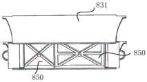
进一步地,还包括打印成型部,打印成型部包括外壳,外壳固定在支架上;外壳具有内部空间,内部空间中设有分隔壁830,分隔壁830将外壳的内部空间分割成成型腔、储粉腔,成型腔、储粉腔均具有下端开口;成型腔、储粉腔的下方分别设置有电动推杆840,电动推杆840的输出端分别穿设在相应的下端开口中,且电动推杆840的输出端均连接有活塞板850,活塞板850分别位于成型腔和储粉腔中,以通过电动推杆840带动活塞板850上下运动。Further, it also includes a printing and forming part, the printing and forming part includes a casing, and the casing is fixed on the bracket; the casing has an inner space, and a partition wall 830 is arranged in the inner space, and the partition wall 830 divides the inner space of the casing into a forming cavity, a powder storage Cavity, forming cavity and powder storage cavity all have lower end openings;
具体地,如图12-15所示,外壳可以包括相对设置的侧壁831和连接两侧壁的端壁832,其中,侧壁831可以是矩形板,端壁832可以是矩形板。侧壁831和端壁832之间形成有内部空间,在内部空间中设有分隔壁830,分隔壁830将外壳的内部空间分割成成型腔和储粉腔,可以理解的,分隔壁830的一侧是成型腔,分隔壁830的另一侧是储粉腔。Specifically, as shown in FIGS. 12-15 , the housing may include
外壳固定在支架上,可选的,外壳可以与支撑杆810固定相连,比如,外壳的相对设置的侧壁831可以分别与支撑杆810的侧壁通过螺纹连接,侧壁831上开有螺纹孔,支撑杆810的侧壁的相应位置开有螺纹孔,螺钉依次插设在侧壁831的螺纹孔、支撑杆810的螺纹孔中,以使外壳固定在支架上。其中,外壳的上端和下端均具有开口,外壳的上端面可以与支撑杆810的上端面平齐。The casing is fixed on the bracket. Optionally, the casing can be fixedly connected to the
成型腔是打印发生的场所,成型腔的下端具有下端开口,成型腔的下方设置有电动推杆840,电动推杆840的输出端穿设在成型腔的下端开口中。电动推杆840的输出端通过联轴器860与活塞板850相连,以使电动推杆推动活塞板850在成型腔中上下运动。The molding cavity is the place where printing occurs. The lower end of the molding cavity has a lower end opening, and an
其中,活塞板850为与成型腔的横截面配合的板状结构,且活塞板850的下端设有加强筋,以提高活塞板的强度。可选的,活塞板850可以与成型腔的内部腔体之间密封配合,以防止活塞板上的材料泄漏。The
储粉腔用于储存待打印的粉末材料,储粉腔的下端具有下端开口,成储粉腔的下方设置有电动推杆840,电动推杆840的输出端穿设在储粉腔的下端开口中。电动推杆840的输出端通过联轴器860与活塞板850相连,以使电动推杆推动活塞板850在储粉腔中上下运动。The powder storage cavity is used to store the powder material to be printed. The lower end of the powder storage cavity has a lower end opening, and an
其中,活塞板850为与储粉腔的横截面配合的板状结构,且活塞板850的下端设有加强筋,以提高活塞板的强度。可选的,活塞板850可以与储粉腔的内部腔体之间密封配合,以防止活塞板上的材料泄漏。Wherein, the
本实施例提供的一种铺粉式3D打印机,通过分隔壁830将外壳的内部空间分割成成型腔和储粉腔,通过在成型腔和储粉腔的下方分别设置电动推杆840,通过在电动推杆840的输出端连接活塞板303,便于实现电动推杆840带动活塞板850上下移动,同时,由于电动推杆的灵敏度比较高,使得电动推杆推动活塞板850上下移动时的精确性较高,提高了每一个打印层的精确性,进而提高了打印机的整体打印精度。In a powder-spreading 3D printer provided in this embodiment, the inner space of the casing is divided into a molding cavity and a powder storage cavity by a partition wall 830 , and
进一步地,外壳包括相对设置的侧壁831和连接侧壁的端壁832,侧壁831的两端伸出端壁832;打印成型部还包括回收本体,回收本体与伸出端壁832的侧壁831、端壁832围设成上端开口的回收腔;回收本体可滑动地设置在侧壁831上。Further, the housing includes
具体地,回收本体可以包括横向板和纵向板,横向板的下端与纵向板的一端相连,且横向板可以垂直于纵向板设置。其中,横向板安装两个侧壁831上,且横向板与两个侧壁831为滑动连接,比如,两个侧壁831上分别设有滑轨,且滑轨的延伸方向平行于横向板的延伸方向,横向板的朝向侧壁831的两侧相对应位置设有与滑轨配合的导向槽,以便于实现二者之间的相对滑动。Specifically, the recovery body may include a transverse plate and a longitudinal plate, the lower end of the transverse plate is connected with one end of the longitudinal plate, and the transverse plate may be arranged perpendicular to the longitudinal plate. The transverse plate is installed on the two
回收本体与伸出端壁的侧壁831、端壁832围设成上端开口的回收腔,以便于回收打印材料。可选的,本实施例中可以形成两个回收腔,可以理解的,相对设置的两个端壁832、两端均伸出端壁的侧壁831、回收本体围设成两个回收腔,进一步提高打印材料的回收率,以节约成本。The recovery body, the
可选的,纵向板背离端壁832的一侧可以设有拉手,以便于拉动回收本体相对于端壁832滑动。拉手可以为类似于U形的结构,拉手可以通过螺纹连接的方式与纵向板连接,比如,拉手上设有紧固孔,纵向板上设有螺纹孔,通过将螺纹经紧固孔插设到螺纹孔中,实现拉手与紧固孔的固定连接。Optionally, a pull handle may be provided on the side of the longitudinal plate away from the end wall 832 to facilitate pulling the recovery body to slide relative to the end wall 832 . The handle can be similar to a U-shaped structure, and the handle can be connected to the longitudinal plate by means of screw connection. For example, the handle is provided with a fastening hole, and the longitudinal plate is provided with a threaded hole. In the threaded hole, the fixed connection between the handle and the fastening hole is realized.
本实施例提供的一种铺粉式3D打印机,通过将回收本体与伸出端壁的侧壁831、端壁832围设成上端开口的回收腔,利于打印材料的回收,节约打印成本。In the powder-spreading 3D printer provided in this embodiment, the recycling body, the
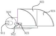
进一步地,还包括铺粉装置,铺粉装置安装在第一Y方向传动带710和第二Y方向传动带720上;铺粉装置包括铺粉辊910和刮板920,刮板920位于铺粉辊910朝向成型腔一侧;刮板920设有与铺粉辊910配合的弧面,刮板920通过弧面与铺粉辊910转动配合。Further, it also includes a powder spreading device, and the powder spreading device is installed on the first Y-
具体地,如图17-18所示,铺粉辊910可以为圆柱,可选的,铺粉辊910的两端均设有转轴911。其中,铺粉辊910的圆柱度可以是0.01mm,以便于铺粉,但是,铺粉辊910的圆柱度并不仅限于此,此处只是举例说明。Specifically, as shown in FIGS. 17-18 , the
铺粉辊910安装在第一Y方向传动带710和第二Y方向传动带720上,可选的,铺粉辊910可以通过转轴911安装在第一Y方向传动带710和第二Y方向传动带720上。The
刮板920包括沿铺粉辊的轴向延伸的第一固定板921,第一固定板921朝向刮板920的一端设有第一翻折边922,第一翻折边922沿铺粉辊910的轴向延伸,且第一翻折边922上设有与铺粉辊配合的弧面。铺粉辊910与刮板920之间相接触的弧面上设置有硅胶或者毛刷等材料,防止由于铺粉辊910上的静电而沾结粉末材料。其中,第一固定板921的两端均设有凸起923,凸起923可以为柱状,比如圆柱或棱柱,凸起923可以为板状,比如矩形板。The
刮板920安装在第一Y方向传动带710和第二Y方向传动带720上,可选的,刮板920可以通过凸起923安装在第一Y方向传动带710和第二Y方向传动带720上。The
刮板920位于铺粉辊910朝向成型腔一侧,以便于在进行铺粉时先刮后铺,实现相邻打印层之间的紧密连接。The
本实施例提供的一种铺粉式3D打印机,通过在第一Y方向传动带710和第二Y方向传动带720上安装铺粉装置,通过设置包括铺粉辊910和刮板920的铺粉装置,通过在刮板920上设置与铺粉辊910相配合的弧面,能够将铺粉辊上的粉末材料刮除。In the powder spreading type 3D printer provided in this embodiment, by installing a powder spreading device on the first Y-
可选的,铺粉装置还包括固定架930,固定架930安装在第一Y方向传动带710和第二Y方向传动带720上,铺粉辊910可转动地安装在固定架930上,刮板920与固定架930固定连接。Optionally, the powder spreading device further includes a fixing
具体地,固定架930有两个,固定架930可以包括第一连接板,第一连接板的两端分别向下翻折形成第二连接板和第三连接板。固定架930上安装有轴承931,第二连接板上设有第一通孔,第三连接板的相应位置设有第二通孔,将轴承931穿过第一通孔和第二通孔后固定在第一连接板和第二连接板上。Specifically, there are two fixing
两个固定架930中的一个通过第一连接板搭设在第一Y方向传动带710,另一个固定架930通过第一连接板搭设在第二Y方向传动带720上。铺粉辊910的其中一个转轴911插设在其中一个固定架的轴承中,铺粉辊910的另一个转轴911插设在另一个固定架的轴承中,步进电机932的输出端与其中一个转轴911相连,以驱动铺粉辊910旋转。One of the two fixing
刮板920的其中一个凸起923与其中一个固定架的第二连接板通过螺纹相连,刮板920的另一个凸起923与另一个固定架的第二连接板通过螺纹相连,以实现刮板的固定。可选的,凸起可以是板体或柱体,在凸起上设有凸起通孔,在第二连接板的侧壁上设有侧壁通孔,通过将螺钉通过凸起通孔后插设在侧壁通孔中,实现刮板920与固定架930的紧固连接。One of the
本实施例提供的一种铺粉式3D打印机,通过在第一Y方向传动带710和第二Y方向传动带720上安装固定架930,通过将铺粉辊910可转动地安装在固定架930上,通过将刮板920与固定架930固定连接,便于实现铺粉辊910与刮板920的固定。In the powder spreading type 3D printer provided in this embodiment, the fixing
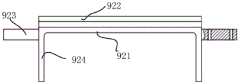
可选的,如图19-21所示,刮板包括沿铺粉辊910的轴向延伸的第一固定板921,第一固定板921朝向铺粉辊910的一侧设有第一翻折边922,第一翻折边922朝向铺粉辊910的一侧具有弧面,以与铺粉辊9100配合;第一固定板921沿铺粉辊910的轴向延伸的两端固定有侧板924,侧板924向背离铺粉辊910的一侧延伸,且侧板924的下端面高于弧面。具体地,如图17-19所示,第一固定板921为板状,且第一固定板921沿铺粉辊910的轴向延伸,可选的,第一固定板921的延伸方向的长度可以与铺粉辊910的轴向相同。第一固定板921朝向铺粉辊910的一侧设有第一翻折边922,第一翻折边922上设有与铺粉辊910相配合的弧面。Optionally, as shown in FIGS. 19-21 , the scraper includes a
侧板924可以是圆心角为90度的弧形板,弧形板包括两个侧壁和外圆周侧壁,两个侧壁中的一个与第一固定板921的一端固定连接,两个侧壁中的另一个侧壁垂直于第一固定板921。其中,第一固定板921上固定有两个侧板924,两个侧板924分别位于第一固定板921的两端,且侧板924朝向背离铺粉辊910的一侧延伸。侧板924主要是为了防止铺粉时,刮板前方堆积的粉末材料从侧面漏出。The
侧板924的另一个侧壁的高度高于第一翻折边922,以使大部分的粉末材料聚集在第一固定板921背离铺粉辊910的一侧,小部分的粉末材料聚集在刮板下面,实现打印层的正常打印。同时,由于侧壁831的上端面高于第一固定板921的下端面,侧壁831能够防止粉末材料的泄露。The height of the other side wall of the
采用本实施例提供的一种铺粉式3D打印机,在进行打印前,铺粉辊、刮板及X方向传动带730位于初始位置,此时,铺粉辊和刮板位于储粉腔的上端,X方向传动带730位于铺粉辊背离成型腔的一侧。当需要进行打印时,第一Y方向传动带710和第二Y方向传动带720转动,并带动安装在其上的铺粉辊、刮板及X方向传动带730向成型腔一侧运动,储粉腔中的电动推杆840推动活塞板850向上运动,成型腔中的电动推杆840推动活塞板850向上运动,刮板将储粉腔中的粉末材料刮至成型腔的上端,铺粉辊将刮板刮至成型腔上端的粉末材料进行铺实,搭设在X方向传动带730上的喷头将流体喷至铺粉辊铺实的打印层,待喷液完毕后,第一个打印层打印完毕;支撑杆810上的气缸推动第一旋转轴和第二旋转轴向上运动,第一驱动件和第二驱动件反转使得第一Y方向传动带710和第二Y方向传动带720反向转动至初始位置,成型腔下的电动推杆840下降一个打印层距离,储粉腔下的电动推杆840上移一个打印层距离,气缸下移,进行下一个打印层的打印。Using the powder spreading type 3D printer provided in this embodiment, before printing, the powder spreading roller, the scraper and the
本实施例提供的一种铺粉式3D打印机,通过将铺粉辊与刮板配合使用,能够防止刮板刮至其背离铺粉辊一侧非粉末溅出并散落在已经铺实的打印层上,同时,刮板上与铺粉辊配合的弧面上设置的材料可以刮除铺粉辊上的粉末材料。In a powder spreading 3D printer provided in this embodiment, by using the powder spreading roller and the scraper in combination, the scraper can prevent the scraper from being scraped to the side away from the powder spreading roller, and the non-powder splashes and scatters on the already laid printing layer. At the same time, the material arranged on the arc surface of the scraper plate matched with the powder spreading roller can scrape the powder material on the powder spreading roller.
在本说明书的描述中,参考术语“一个实施例”、“一些实施例”、“示意性实施例”、“示例”、“具体示例”、或“一些示例”等的描述意指结合该实施例或示例描述的具体特征、结构、材料或者特点包含于本公开的至少一个实施例或示例中。在本说明书中,对上述术语的示意性表述不一定指的是相同的实施例或示例。而且,描述的具体特征、结构、材料或者特点可以在任何的一个或多个实施例或示例中以合适的方式结合。In the description of this specification, reference to the terms "one embodiment," "some embodiments," "exemplary embodiment," "example," "specific example," or "some examples", etc., is meant to incorporate the embodiments A particular feature, structure, material, or characteristic described by an example or example is included in at least one embodiment or example of the present disclosure. In this specification, schematic representations of the above terms do not necessarily refer to the same embodiment or example. Furthermore, the particular features, structures, materials or characteristics described may be combined in any suitable manner in any one or more embodiments or examples.
应当理解的是,尽管本公开已经示出了一些实施例,但是本领域的普通技术人员可以理解,在不脱离本发明的原理和宗旨的情况下可以对这些实施例进行多种变化、修改、替换和变型,本公开的范围由权利要求及其等同物限定。It should be understood that although the present disclosure has shown some embodiments, those of ordinary skill in the art will appreciate that various changes, modifications, Alternatives and modifications, the scope of the present disclosure is defined by the claims and their equivalents.
Claims (9)
Priority Applications (1)
| Application Number | Priority Date | Filing Date | Title |
|---|---|---|---|
| CN201810782473.XACN109263038B (en) | 2018-07-17 | 2018-07-17 | Spread powder formula 3D printer |
Applications Claiming Priority (1)
| Application Number | Priority Date | Filing Date | Title |
|---|---|---|---|
| CN201810782473.XACN109263038B (en) | 2018-07-17 | 2018-07-17 | Spread powder formula 3D printer |
Publications (2)
| Publication Number | Publication Date |
|---|---|
| CN109263038A CN109263038A (en) | 2019-01-25 |
| CN109263038Btrue CN109263038B (en) | 2020-01-17 |
Family
ID=65152882
Family Applications (1)
| Application Number | Title | Priority Date | Filing Date |
|---|---|---|---|
| CN201810782473.XAActiveCN109263038B (en) | 2018-07-17 | 2018-07-17 | Spread powder formula 3D printer |
Country Status (1)
| Country | Link |
|---|---|
| CN (1) | CN109263038B (en) |
Families Citing this family (1)
| Publication number | Priority date | Publication date | Assignee | Title |
|---|---|---|---|---|
| CN109808176B (en)* | 2019-03-18 | 2021-03-16 | 北京工业大学 | Powder type 3D printer powder paving mechanism based on isolation bowl |
Citations (2)
| Publication number | Priority date | Publication date | Assignee | Title |
|---|---|---|---|---|
| WO2017218645A1 (en)* | 2016-06-14 | 2017-12-21 | Nike Innovate C.V. | Spring-loaded nozzle assemblies |
| CN108177335A (en)* | 2018-03-15 | 2018-06-19 | 北京化工大学 | Melt solid two-phase 3D printer |
Family Cites Families (10)
| Publication number | Priority date | Publication date | Assignee | Title |
|---|---|---|---|---|
| CN201108875Y (en)* | 2007-09-11 | 2008-09-03 | 比亚迪股份有限公司 | a nozzle |
| US10562227B2 (en)* | 2015-12-01 | 2020-02-18 | Massachusetts Institute Of Technology | Systems, devices, and methods for high-throughput three-dimensional printing |
| CN105729127B (en)* | 2016-05-05 | 2019-04-02 | 安徽中科镭泰激光科技有限公司 | A laser manufacturing teaching machine |
| US20170326773A1 (en)* | 2016-05-16 | 2017-11-16 | Ord Solutions Inc. | Fused filament fabrication color extruder for three dimensional printing |
| CN205915701U (en)* | 2016-08-08 | 2017-02-01 | 王成岩 | Portable 3D printer |
| US10953598B2 (en)* | 2016-11-04 | 2021-03-23 | Continuous Composites Inc. | Additive manufacturing system having vibrating nozzle |
| CN106578317A (en)* | 2016-11-24 | 2017-04-26 | 张云玖 | 3D (Three-Dimensional) ice cream printer, 3D ice cream printing method and product thereof |
| CN106583714A (en)* | 2016-12-22 | 2017-04-26 | 中山市新泰兴粉末冶金有限公司 | 3d printer |
| CN107263866A (en)* | 2017-05-25 | 2017-10-20 | 安徽恒利增材制造科技有限公司 | A kind of double feeding cylinder 3d printer |
| CN107984755B (en)* | 2017-11-30 | 2019-09-10 | 南京师范大学 | A kind of 3D printer and its forming method of the double molding modes of high-precision |
- 2018
- 2018-07-17CNCN201810782473.XApatent/CN109263038B/enactiveActive
Patent Citations (2)
| Publication number | Priority date | Publication date | Assignee | Title |
|---|---|---|---|---|
| WO2017218645A1 (en)* | 2016-06-14 | 2017-12-21 | Nike Innovate C.V. | Spring-loaded nozzle assemblies |
| CN108177335A (en)* | 2018-03-15 | 2018-06-19 | 北京化工大学 | Melt solid two-phase 3D printer |
Also Published As
| Publication number | Publication date |
|---|---|
| CN109263038A (en) | 2019-01-25 |
Similar Documents
| Publication | Publication Date | Title |
|---|---|---|
| CN109263038B (en) | Spread powder formula 3D printer | |
| CN215541888U (en) | Spray nozzle of spraying machine | |
| CN109403595A (en) | a paint roller | |
| CN118083205B (en) | Paste material constant temperature filling equipment | |
| CN213855175U (en) | A portable dirt equipment that presses down for building engineering | |
| CN217137936U (en) | Cleaning assembly and cleaning robot | |
| JP2013068046A (en) | Road printer | |
| JP6057419B2 (en) | High viscosity fluid applicator | |
| CN109898804A (en) | A kind of building coating spraying equipment | |
| KR102100414B1 (en) | Fluid delivery system | |
| CN220405440U (en) | Graphene modified solvent-free flexible polysiloxane coating stirring pile | |
| CN223237211U (en) | Code spraying device | |
| CN220310856U (en) | Automatic gluing machine | |
| CN222502789U (en) | Reversing ball valve and intelligent color mixing machine | |
| JP4629515B2 (en) | Piston pump | |
| CN209308362U (en) | A kind of true stone spraying roller of hand-held | |
| CN219920074U (en) | Corn planting pesticide spraying machine | |
| CN117920484B (en) | Casting surface paint spraying device | |
| CN217550128U (en) | Spraying device for wooden furniture | |
| CN223300344U (en) | Portable paint brushing device | |
| CN112316819B (en) | Pneumatic high-efficiency water-based paint dispersing process system | |
| CN221500657U (en) | Microbial inoculum medicament scattering equipment for river course treatment | |
| CN223360274U (en) | Anticorrosive paint smearing device for flue gas pipeline | |
| CN111701525A (en) | injection components | |
| CN221016702U (en) | Spraying coater for road construction |
Legal Events
| Date | Code | Title | Description |
|---|---|---|---|
| PB01 | Publication | ||
| PB01 | Publication | ||
| SE01 | Entry into force of request for substantive examination | ||
| SE01 | Entry into force of request for substantive examination | ||
| GR01 | Patent grant | ||
| GR01 | Patent grant |