CN109212877B - Optical unit and projector including the same - Google Patents
Optical unit and projector including the sameDownload PDFInfo
- Publication number
- CN109212877B CN109212877BCN201810716321.XACN201810716321ACN109212877BCN 109212877 BCN109212877 BCN 109212877BCN 201810716321 ACN201810716321 ACN 201810716321ACN 109212877 BCN109212877 BCN 109212877B
- Authority
- CN
- China
- Prior art keywords
- light
- prism
- projection
- incident
- illumination light
- Prior art date
- Legal status (The legal status is an assumption and is not a legal conclusion. Google has not performed a legal analysis and makes no representation as to the accuracy of the status listed.)
- Active
Links
Images


Classifications
- G—PHYSICS
- G03—PHOTOGRAPHY; CINEMATOGRAPHY; ANALOGOUS TECHNIQUES USING WAVES OTHER THAN OPTICAL WAVES; ELECTROGRAPHY; HOLOGRAPHY
- G03B—APPARATUS OR ARRANGEMENTS FOR TAKING PHOTOGRAPHS OR FOR PROJECTING OR VIEWING THEM; APPARATUS OR ARRANGEMENTS EMPLOYING ANALOGOUS TECHNIQUES USING WAVES OTHER THAN OPTICAL WAVES; ACCESSORIES THEREFOR
- G03B21/00—Projectors or projection-type viewers; Accessories therefor
- G03B21/005—Projectors using an electronic spatial light modulator but not peculiar thereto
- G03B21/008—Projectors using an electronic spatial light modulator but not peculiar thereto using micromirror devices
- G—PHYSICS
- G02—OPTICS
- G02B—OPTICAL ELEMENTS, SYSTEMS OR APPARATUS
- G02B26/00—Optical devices or arrangements for the control of light using movable or deformable optical elements
- G02B26/08—Optical devices or arrangements for the control of light using movable or deformable optical elements for controlling the direction of light
- G02B26/0816—Optical devices or arrangements for the control of light using movable or deformable optical elements for controlling the direction of light by means of one or more reflecting elements
- G02B26/0833—Optical devices or arrangements for the control of light using movable or deformable optical elements for controlling the direction of light by means of one or more reflecting elements the reflecting element being a micromechanical device, e.g. a MEMS mirror, DMD
- G—PHYSICS
- G02—OPTICS
- G02B—OPTICAL ELEMENTS, SYSTEMS OR APPARATUS
- G02B27/00—Optical systems or apparatus not provided for by any of the groups G02B1/00 - G02B26/00, G02B30/00
- G02B27/09—Beam shaping, e.g. changing the cross-sectional area, not otherwise provided for
- G02B27/0938—Using specific optical elements
- G02B27/095—Refractive optical elements
- G02B27/0955—Lenses
- G—PHYSICS
- G02—OPTICS
- G02B—OPTICAL ELEMENTS, SYSTEMS OR APPARATUS
- G02B27/00—Optical systems or apparatus not provided for by any of the groups G02B1/00 - G02B26/00, G02B30/00
- G02B27/09—Beam shaping, e.g. changing the cross-sectional area, not otherwise provided for
- G02B27/0938—Using specific optical elements
- G02B27/095—Refractive optical elements
- G02B27/0972—Prisms
- G—PHYSICS
- G02—OPTICS
- G02B—OPTICAL ELEMENTS, SYSTEMS OR APPARATUS
- G02B27/00—Optical systems or apparatus not provided for by any of the groups G02B1/00 - G02B26/00, G02B30/00
- G02B27/10—Beam splitting or combining systems
- G02B27/1006—Beam splitting or combining systems for splitting or combining different wavelengths
- G—PHYSICS
- G02—OPTICS
- G02B—OPTICAL ELEMENTS, SYSTEMS OR APPARATUS
- G02B27/00—Optical systems or apparatus not provided for by any of the groups G02B1/00 - G02B26/00, G02B30/00
- G02B27/10—Beam splitting or combining systems
- G02B27/12—Beam splitting or combining systems operating by refraction only
- G02B27/126—The splitting element being a prism or prismatic array, including systems based on total internal reflection
- G—PHYSICS
- G03—PHOTOGRAPHY; CINEMATOGRAPHY; ANALOGOUS TECHNIQUES USING WAVES OTHER THAN OPTICAL WAVES; ELECTROGRAPHY; HOLOGRAPHY
- G03B—APPARATUS OR ARRANGEMENTS FOR TAKING PHOTOGRAPHS OR FOR PROJECTING OR VIEWING THEM; APPARATUS OR ARRANGEMENTS EMPLOYING ANALOGOUS TECHNIQUES USING WAVES OTHER THAN OPTICAL WAVES; ACCESSORIES THEREFOR
- G03B21/00—Projectors or projection-type viewers; Accessories therefor
- G03B21/14—Details
- G03B21/20—Lamp housings
- G03B21/206—Control of light source other than position or intensity
- G—PHYSICS
- G03—PHOTOGRAPHY; CINEMATOGRAPHY; ANALOGOUS TECHNIQUES USING WAVES OTHER THAN OPTICAL WAVES; ELECTROGRAPHY; HOLOGRAPHY
- G03B—APPARATUS OR ARRANGEMENTS FOR TAKING PHOTOGRAPHS OR FOR PROJECTING OR VIEWING THEM; APPARATUS OR ARRANGEMENTS EMPLOYING ANALOGOUS TECHNIQUES USING WAVES OTHER THAN OPTICAL WAVES; ACCESSORIES THEREFOR
- G03B21/00—Projectors or projection-type viewers; Accessories therefor
- G03B21/14—Details
- G03B21/20—Lamp housings
- G03B21/2066—Reflectors in illumination beam
- G—PHYSICS
- G03—PHOTOGRAPHY; CINEMATOGRAPHY; ANALOGOUS TECHNIQUES USING WAVES OTHER THAN OPTICAL WAVES; ELECTROGRAPHY; HOLOGRAPHY
- G03B—APPARATUS OR ARRANGEMENTS FOR TAKING PHOTOGRAPHS OR FOR PROJECTING OR VIEWING THEM; APPARATUS OR ARRANGEMENTS EMPLOYING ANALOGOUS TECHNIQUES USING WAVES OTHER THAN OPTICAL WAVES; ACCESSORIES THEREFOR
- G03B21/00—Projectors or projection-type viewers; Accessories therefor
- G03B21/14—Details
- G03B21/28—Reflectors in projection beam
Landscapes
- Physics & Mathematics (AREA)
- General Physics & Mathematics (AREA)
- Optics & Photonics (AREA)
- Projection Apparatus (AREA)
- Optical Elements Other Than Lenses (AREA)
- Optical Filters (AREA)
Abstract
Translated fromChinese
Description
Translated fromChinese技术领域technical field
本发明涉及入射照明光并射出由数字微镜器件反射的投影光的光学单元以及具备该光学单元的投影仪。The present invention relates to an optical unit that enters illumination light and emits projection light reflected by a digital micromirror device, and a projector equipped with the optical unit.
背景技术Background technique
专利文献1公开了搭载有以往的光学单元的投影仪。该投影仪具备光源、光学单元、多个数字微镜器件(Digital Micromirror Device)以及投影透镜。光学单元具有全反射型光分离棱镜以及十字分色棱镜。从投影侧(射出侧)朝向数字微镜器件依次配置有全反射型光分离棱镜以及十字分色棱镜。Patent Document 1 discloses a projector equipped with a conventional optical unit. The projector includes a light source, an optical unit, a plurality of Digital Micromirror Devices, and a projection lens. The optical unit has a total reflection type light separation prism and a cross dichroic prism. A total reflection type light separation prism and a cross dichroic prism are arranged in this order from the projection side (exit side) toward the digital micromirror device.
数字微镜器件是俯视时为矩形的反射型图像显示元件,具有由多个微小的微镜构成的图像显示面。数字微镜器件通过对各微镜的面的倾斜进行ON/OFF控制而对照明光进行强度调制,来生成投影光并形成图像。各微镜以数字微镜器件的一个转动轴为中心转动,ON状态的微镜的倾斜角度与OFF状态的微镜的倾斜角度不同。The digital micromirror device is a reflective image display element that is rectangular in plan view, and has an image display surface composed of a plurality of tiny micromirrors. In the digital micromirror device, the intensity of illumination light is modulated by ON/OFF control of the inclination of the surface of each micromirror, thereby generating projection light and forming an image. Each micromirror rotates around a rotation axis of the digital micromirror device, and the inclination angle of the micromirror in the ON state is different from the inclination angle of the micromirror in the OFF state.
全反射型光分离棱镜由2个棱镜构成,一个棱镜具有射出面,另一个棱镜具有入射面及全反射面,并且具有相对于射出面向射出方向突出的突出部。全反射面的一部分设置于突出部,将从入射面入射到全反射型光分离棱镜的白色的照明光朝向十字分色棱镜全反射。射出面与投影透镜对置地配置,将由数字微镜器件生成的投影光朝向投影透镜射出。The total reflection type light separation prism is composed of two prisms, one prism has an exit surface, the other prism has an entrance surface and a total reflection surface, and has a protrusion protruding in the exit direction with respect to the exit surface. A part of the total reflection surface is provided in the protruding portion, and the white illumination light incident on the total reflection type light separation prism from the incident surface is totally reflected toward the cross dichroic prism. The emitting surface is arranged opposite to the projection lens, and emits the projection light generated by the digital micromirror device toward the projection lens.
十字分色棱镜具有正交的2个二向色涂层面,将被全反射型光分离棱镜的全反射面全反射的白色的照明光分解成红色成分、绿色成分以及蓝色成分并分别向各数字微镜器件引导。另外,十字分色棱镜对由各数字微镜器件的ON状态的微镜反射的红色、绿色以及蓝色的ON光(投影光)进行颜色合成,并将颜色合成后的ON光朝向全反射型光分离棱镜射出。十字分色棱镜的最靠射出面侧的面与射出面平行,与颜色合成后的ON光的光轴垂直。The cross dichroic prism has two orthogonal dichroic coating surfaces, and decomposes the white illumination light that is totally reflected by the total reflection surface of the total reflection type light separation prism into red, green, and blue components and sends them to each of them. Each digital micromirror device guides. In addition, the cross dichroic prism performs color synthesis on red, green, and blue ON light (projection light) reflected by the ON-state micromirror of each digital micromirror device, and the ON light after color synthesis is directed toward the total reflection type The light splitting prism exits. The surface of the cross dichroic prism closest to the output surface is parallel to the output surface and perpendicular to the optical axis of the ON light after color synthesis.
在上述结构的投影仪中,从光源出射并入射到全反射型光分离棱镜的白色的照明光在由全反射型光分离棱镜的全反射面全反射后从全反射型光分离棱镜出射并入射到十字分色棱镜。入射到十字分色棱镜的照明光被颜色分解,照明光的红色成分、绿色成分以及蓝色成分朝向相互不同的数字微镜器件出射。In the projector of the above configuration, the white illumination light emitted from the light source and incident on the total reflection type light separation prism is totally reflected by the total reflection surface of the total reflection type light separation prism and then exits from the total reflection type light separation prism and enters to a cross dichroic prism. The illumination light incident on the cross dichroic prism is decomposed by color, and the red component, the green component, and the blue component of the illumination light are emitted toward mutually different digital micromirror devices.
而且,由各数字微镜器件的ON状态的微镜反射的红色、绿色以及蓝色的ON光被入射到十字分色棱镜并进行颜色合成,之后朝向全反射型光分离棱镜出射。颜色合成后的ON光在透过全反射型光分离棱镜的全反射面后从射出面射出,透过投影透镜。由此,投影出彩色图像。The red, green, and blue ON light reflected by the ON-state micromirror of each digital micromirror device is incident on the cross dichroic prism, undergoes color synthesis, and then exits toward the total reflection type light separation prism. The color-combined ON light passes through the total reflection surface of the total reflection type light separation prism, then exits from the output surface and passes through the projection lens. Thereby, a color image is projected.
专利文献1:日本特开2007-25287号公报(第5页、第6页、第1图、第3图)Patent Document 1: Japanese Patent Laid-Open No. 2007-25287 (pages 5, 6, Fig. 1, Fig. 3)
一般来说,在投影仪中,使投影透镜向上下方向或左右方向移动来变更投影图像的投影位置。即,在投影仪中进行投影透镜的上下移位、左右移位。然而,根据上述以往的光学单元,全反射型光分离棱镜具有向射出方向突出的突出部,投影透镜被配置在突出部的侧方附近。因此,限制了投影透镜的左右方向的移动而投影透镜的左右移位量(能够向左右方向移动的距离)变小。另外,在全反射型光分离棱镜的突出部被配置在投影透镜的下方附近的情况下,限制了投影透镜的上下方向的移动而投影透镜的上下移位量(能够向上下方向移动的距离)变小。因此,存在光学单元以及投影仪的使用性降低的问题。Generally, in a projector, the projection position of the projected image is changed by moving the projection lens in the up-down direction or in the left-right direction. That is, in the projector, the vertical displacement and the horizontal displacement of the projection lens are performed. However, according to the above-described conventional optical unit, the total reflection type light splitting prism has the protruding portion that protrudes in the emission direction, and the projection lens is arranged in the vicinity of the side of the protruding portion. Therefore, the movement in the left-right direction of the projection lens is restricted, and the left-right displacement amount (distance that can be moved in the left-right direction) of the projection lens becomes small. In addition, when the protruding portion of the total reflection type light splitting prism is arranged near the lower part of the projection lens, the vertical movement of the projection lens is restricted and the vertical displacement amount of the projection lens (distance that can be moved in the vertical direction) is restricted. become smaller. Therefore, there is a problem that the usability of the optical unit and the projector is lowered.
另一方面,若使全反射型光分离棱镜的突出部(全反射面)沿着十字分色棱镜的最靠射出侧的面向远离投影透镜的方向移动,则能够增大投影透镜的左右移位量、上下移位量。然而,在该情况下,有朝向全反射型光分离棱镜的照明光的光束中的十字分色棱镜侧的光线不入射到入射面的情况。此时,若为了使十字分色棱镜侧的照明光的光线入射到入射面而变更照明光向入射面的入射角度,则一部分的照明光不被全反射面全反射而透过。由此,存在因被全反射型光分离棱镜的全反射面全反射的照明光的光量减少而入射到数字微镜器件的照明光的光量减少,从而投影光的光量减少的问题。On the other hand, if the protrusion (total reflection surface) of the total reflection type light splitting prism is moved in the direction away from the projection lens on the most output side surface of the cross dichroic prism, the lateral displacement of the projection lens can be increased. amount, up and down displacement. However, in this case, the light beam on the side of the cross dichroic prism among the luminous fluxes of the illumination light directed toward the total reflection type light splitting prism may not enter the incident surface. At this time, if the incident angle of the illumination light to the incident surface is changed so that the light of the illumination light on the cross dichroic prism side is incident on the incident surface, a part of the illumination light is transmitted without being totally reflected by the total reflection surface. Therefore, there is a problem that the amount of illumination light incident on the digital micromirror device is decreased due to the decrease in the amount of illumination light that is totally reflected by the total reflection surface of the total reflection type light splitting prism, thereby reducing the amount of projection light.
发明内容SUMMARY OF THE INVENTION
本发明的目的在于提供能够防止投影光的光量的减少并且能够提高使用性的光学单元以及具备该光学单元的投影仪。An object of the present invention is to provide an optical unit capable of preventing a decrease in the amount of projection light and improving usability, and a projector including the optical unit.
为了实现上述目的,本发明的光学单元的特征在于,朝向多个数字微镜器件出射照明光并且使由多个上述数字微镜器件生成的投影光透过并射出,上述数字微镜器件根据图像信号在图像显示面对照明光进行调制来生成投影光,在该光学单元中,具备:In order to achieve the above object, the optical unit of the present invention is characterized in that it emits illumination light toward a plurality of digital micromirror devices and transmits and emits the projection light generated by the plurality of digital micromirror devices, the digital micromirror devices according to the image The signal modulates the illumination light on the image display surface to generate projection light, and the optical unit has:
反射部件,具有反射照明光的照明光反射面;以及a reflecting member having an illumination light reflecting surface that reflects the illumination light; and
棱镜单元,由多个第一棱镜形成,将由上述照明光反射面反射的照明光从形成于最靠射出侧的上述第一棱镜的第一面入射并且将投影光从上述第一面出射,The prism unit is formed of a plurality of first prisms, enters the illumination light reflected by the illumination light reflection surface from the first surface of the first prism formed on the most output side, and emits the projection light from the first surface,
上述反射部件接近上述第一面并且比上述第一面向投影光的出射方向突出地配置,The reflecting member is disposed close to the first surface and protruding from the first surface in the outgoing direction of the projection light,
入射到上述照明光反射面的照明光的入射光的光轴和投影光的上述第一面上的光轴被配置在作为同一平面的光轴平面上,The optical axis of the incident light of the illumination light incident on the illumination light reflecting surface and the optical axis of the projection light on the first surface are arranged on the same plane as the optical axis plane,
第一分量矢量朝向随着远离上述第一面而远离从上述第一面出射的投影光的光轴的方向,其中,以在将上述第一面的向外的第一法向矢量投影到上述光轴平面时上述第一分量矢量相对于投影光的光轴配置在与上述入射光的光轴相同侧的方式来将上述第一法向矢量投影到上述光轴平面。The first component vector is oriented in a direction away from the optical axis of the projection light emitted from the first surface as it moves away from the first surface, wherein a first normal vector outwardly projected from the first surface to the first surface On the optical axis plane, the first normal vector is projected onto the optical axis plane so that the first component vector is arranged on the same side as the optical axis of the incident light with respect to the optical axis of the projection light.
另外,本发明的投影仪的特征在于,具备:上述结构的光学单元、光源、朝向上述光学单元的上述反射部件出射照明光的照明光学系统、以及将显示在安装于上述安装部的上述数字微镜器件的图像放大投影到屏幕的投影光学系统。In addition, the projector of the present invention is characterized by comprising: an optical unit having the above-mentioned configuration, a light source, an illumination optical system for emitting illumination light toward the reflecting member of the optical unit, and the digital microcomputer to be displayed on the mounting portion. The projection optical system in which the image of the mirror device is enlarged and projected onto the screen.
根据本发明的光学单元,入射到照明光反射面的照明光的入射光的光轴和投影光的第一面上的光轴被配置在作为同一平面的光轴平面上,第一分量矢量朝向随着远离第一面而远离从第一面出射的投影光的光轴的方向,其中,以在将第一面的向外的第一法向矢量投影到光轴平面时第一分量矢量相对于投影光的光轴配置在与照明光的入射光的光轴相同侧的方式来将第一法向矢量投影到光轴平面。由此,能够防止由照明光反射面全反射的照明光的光量的减少,并且能够增大从第一面出射的第一面附近的投影光的光轴与反射部件之间的在与该投影光的光轴垂直的方向上的距离。因此,在与光学单元的第一面对置地配置投影光学系统的情况下,能够增大投影光学系统的朝向反射部件的方向的移位量。因此,能够防止投影光的光量的减少,并且能够提高光学单元以及投影仪的使用性。According to the optical unit of the present invention, the optical axis of the incident light of the illumination light incident on the illumination light reflection surface and the optical axis of the first surface of the projection light are arranged on the same plane as the optical axis plane, and the first component vector is directed toward The direction away from the optical axis of the projected light emerging from the first face as it moves away from the first face, wherein the first component vector is relative to the The first normal vector is projected onto the optical axis plane so that the optical axis of the projection light is arranged on the same side as the optical axis of the incident light of the illumination light. Accordingly, it is possible to prevent a decrease in the light quantity of the illumination light totally reflected by the illumination light reflection surface, and to increase the distance between the optical axis of the projection light near the first surface emitted from the first surface and the reflection member and the projection The distance in the direction perpendicular to the optical axis of light. Therefore, when the projection optical system is arranged so as to face the first surface of the optical unit, the displacement amount of the projection optical system in the direction toward the reflection member can be increased. Therefore, it is possible to prevent the reduction of the light quantity of the projection light, and to improve the usability of the optical unit and the projector.
附图说明Description of drawings
图1是表示具备本发明的第一实施方式的光学单元的投影仪的概略结构图。FIG. 1 is a schematic configuration diagram showing a projector including an optical unit according to a first embodiment of the present invention.
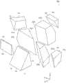
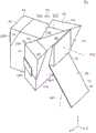
图2是表示本发明的第一实施方式的光学单元的立体图。2 is a perspective view showing an optical unit according to the first embodiment of the present invention.
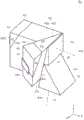
图3是表示本发明的第一实施方式的光学单元的分解立体图。3 is an exploded perspective view showing the optical unit according to the first embodiment of the present invention.
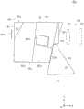
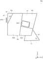
图4是表示本发明的第一实施方式的光学单元的顶视图。4 is a top view showing the optical unit according to the first embodiment of the present invention.
图5是表示本发明的第一实施方式的光学单元的侧视图。5 is a side view showing the optical unit according to the first embodiment of the present invention.
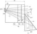
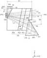
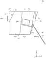
图6是表示本发明的第一实施方式的光学单元的侧剖视图。6 is a side cross-sectional view showing an optical unit according to the first embodiment of the present invention.
图7是表示本发明的第一实施方式的光学单元的数字微镜器件的微镜的基准状态、ON状态以及OFF状态的立体图。7 is a perspective view showing a reference state, an ON state, and an OFF state of a micromirror of the digital micromirror device of the optical unit according to the first embodiment of the present invention.
图8是用于对本发明的第一实施方式的光学单元的数字微镜器件的动作进行说明的立体图。8 is a perspective view for explaining the operation of the digital micromirror device of the optical unit according to the first embodiment of the present invention.
图9是表示针对本发明的第一实施方式的光学单元的数字微镜器件的微镜的照明光、被ON状态的微镜反射的ON光以及被OFF状态的微镜反射的OFF光的示意图。9 is a schematic diagram showing the illumination light of the micromirror of the digital micromirror device of the optical unit of the first embodiment of the present invention, the ON light reflected by the micromirror in the ON state, and the OFF light reflected by the micromirror in the OFF state .
图10是表示比较例的光学单元的侧剖视图。10 is a side cross-sectional view showing an optical unit of a comparative example.
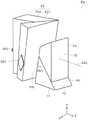
图11是表示本发明的第二实施方式的光学单元的立体图。11 is a perspective view showing an optical unit according to a second embodiment of the present invention.
图12是表示本发明的第二实施方式的光学单元的顶视图。12 is a top view showing an optical unit according to a second embodiment of the present invention.
图13是表示本发明的第二实施方式的光学单元的侧视图。13 is a side view showing an optical unit according to a second embodiment of the present invention.
图14是表示本发明的第二实施方式的光学单元的侧剖视图。14 is a side cross-sectional view showing an optical unit according to a second embodiment of the present invention.
图15是表示本发明的第三实施方式的光学单元的立体图。15 is a perspective view showing an optical unit according to a third embodiment of the present invention.
图16是表示本发明的第三实施方式的光学单元的顶视图。16 is a top view showing an optical unit according to a third embodiment of the present invention.
图17是表示本发明的第三实施方式的光学单元的侧视图。17 is a side view showing an optical unit according to a third embodiment of the present invention.
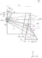
图18是表示本发明的第三实施方式的光学单元的侧剖视图。18 is a side cross-sectional view showing an optical unit according to a third embodiment of the present invention.
图19是表示本发明的第四实施方式的光学单元的立体图。19 is a perspective view showing an optical unit according to a fourth embodiment of the present invention.
图20是表示本发明的第四实施方式的光学单元的侧视图。20 is a side view showing an optical unit according to a fourth embodiment of the present invention.
图21是表示本发明的第四实施方式的光学单元的侧剖视图。21 is a side cross-sectional view showing an optical unit according to a fourth embodiment of the present invention.
图22是表示本发明的第五实施方式的光学单元的立体图。22 is a perspective view showing an optical unit according to a fifth embodiment of the present invention.
图23是表示本发明的第五实施方式的光学单元的顶视图。23 is a top view showing an optical unit according to a fifth embodiment of the present invention.
图24是表示本发明的第五实施方式的光学单元的侧视图。24 is a side view showing an optical unit according to a fifth embodiment of the present invention.
图25是表示本发明的第五实施方式的光学单元的侧剖视图。25 is a side cross-sectional view showing an optical unit according to a fifth embodiment of the present invention.
图26是用于对本发明的第五实施方式的光学单元的数字微镜器件的动作进行说明的立体图。26 is a perspective view for explaining the operation of the digital micromirror device of the optical unit according to the fifth embodiment of the present invention.
图27是表示本发明的第六实施方式的光学单元的立体图。27 is a perspective view showing an optical unit according to a sixth embodiment of the present invention.
图28是表示本发明的第六实施方式的光学单元的顶视图。28 is a top view showing an optical unit according to a sixth embodiment of the present invention.
图29是表示本发明的第六实施方式的光学单元的侧剖视图。29 is a side cross-sectional view showing an optical unit according to a sixth embodiment of the present invention.
附图标记说明:PJ...投影仪;LN...投影光学系统;PU...光学单元;PM...光吸收部件;DP、DP1、DP2、DP3...数字微镜器件;DS...图像显示面;MR...微镜;MS...像素反射面;CG...盖玻璃;P1...内部全反射棱镜(反射部件);P2...颜色分解合成棱镜单元(棱镜单元);P21~P23...棱镜(第一棱镜);P3...投影侧棱镜(第二棱镜);P4...OFF光分离棱镜(第三棱镜);L1...照明光;L2...ON光(投影光);L3...OFF光(无效光);AX...光轴;AX1...照明光的光轴;AX2...投影光(ON光)的光轴;AX3...OFF光的光轴;MS2...ON反射面;MS3...OFF反射面;SC...屏幕;DR、DB...二向色涂层面;1...光源;2...照明光学系统;3...控制部;4...促动器;11...入射面;12...照明光反射面;13...出射面;21a、22a、23a...入射出射面;21b...入射出射面(第一面);21t、23t...全反射面;31...入射面;32...出射面(第二面);51、52...投影透镜。DESCRIPTION OF REFERENCE NUMERALS: PJ...projector; LN...projection optical system; PU...optical unit; PM...light absorbing component; DP, DP1, DP2, DP3...digital micromirror device; DS...image display surface; MR...micromirror; MS...pixel reflection surface; CG...cover glass; P1...internal total reflection prism (reflection part); P2...color decomposition and synthesis Prism unit (prism unit); P21~P23...prism (first prism); P3...projection side prism (second prism); P4...OFF light separation prism (third prism); L1... Illumination light; L2...ON light (projection light); L3...OFF light (inactive light); AX...optical axis; AX1...optical axis of illumination light; AX2...projection light (ON optical axis of light); AX3...OFF optical axis of light; MS2...ON reflecting surface; MS3...OFF reflecting surface; SC...screen; DR, DB...dichroic coating surface ;1...light source; 2...illumination optical system; 3...control unit; 4...actuator; 11...incidence surface; 12...illumination light reflection surface; 13... Exit surface; 21a, 22a, 23a...incident and exit surface; 21b...incident exit surface (first surface); 21t, 23t...total reflection surface; 31...incidence surface; 32...exit face (second face); 51, 52...projection lens.
具体实施方式Detailed ways
<第一实施方式><First Embodiment>
以下参照附图对本发明的实施方式进行说明。图1示出具备第一实施方式的光学单元的投影仪的概略结构图。3芯片类型(三板式)的投影仪PJ具备光源1、照明光学系统2、光学单元PU、数字微镜器件DP1、DP2、DP3(也参照图4)、投影光学系统LN、促动器4以及控制部3。Embodiments of the present invention will be described below with reference to the accompanying drawings. FIG. 1 is a schematic configuration diagram of a projector including an optical unit according to the first embodiment. The 3-chip type (three-plate type) projector PJ includes a light source 1, an illumination
光源1例如由LED构成,出射白光。照明光学系统2具有积分器、中继透镜组以及反射镜等(均未图示)。照明光学系统2对光源1的出射光进行聚光并作为照明光L1朝向光学单元PU出射。The light source 1 is composed of, for example, an LED, and emits white light. The illumination
图2示出光学单元PU的立体图。在图2中,X方向表示颜色分解合成棱镜单元P2的厚度方向。Z方向表示由数字微镜器件DP2反射的投影光的光轴AX2方向。Y方向表示与X方向以及Z方向垂直的方向。光学单元PU具有一个内部全反射棱镜P1(反射部件)、一个颜色分解合成棱镜单元P2(棱镜单元)、一个投影侧棱镜P3(第二棱镜)以及三个OFF光分离棱镜P4(第三棱镜)。颜色分解合成棱镜P2具有棱镜P21(第一棱镜)、棱镜P22(第一棱镜)以及棱镜P23(第一棱镜)。FIG. 2 shows a perspective view of the optical unit PU. In FIG. 2, the X direction represents the thickness direction of the color separation synthesis prism unit P2. The Z direction represents the direction of the optical axis AX2 of the projection light reflected by the digital micromirror device DP2. The Y direction represents a direction perpendicular to the X direction and the Z direction. The optical unit PU has one internal total reflection prism P1 (reflection member), one color separation synthesis prism unit P2 (prism unit), one projection side prism P3 (second prism), and three OFF light separation prisms P4 (third prism). The color separation and synthesis prism P2 has a prism P21 (first prism), a prism P22 (first prism), and a prism P23 (first prism).
作为内部全反射棱镜P1、颜色分解合成棱镜单元P2的棱镜P21~P23、投影侧棱镜P3以及OFF光分离棱镜P4的材质,例如能够使用玻璃。在本实施方式中,内部全反射棱镜P1、棱镜P21、P22、P23、投影侧棱镜P3以及OFF光分离棱镜P4由折射率相同的玻璃形成。As the material of the total internal reflection prism P1, the prisms P21 to P23 of the color separation and synthesis prism unit P2, the projection side prism P3, and the OFF light separation prism P4, for example, glass can be used. In the present embodiment, the total internal reflection prism P1, the prisms P21, P22, and P23, the projection-side prism P3, and the OFF light separation prism P4 are formed of glass having the same refractive index.
光学单元PU在投影仪PJ内被支承部件(未图示)支承。支承部件与光学单元PU的图2中的上下表面接触地配置,夹持光学单元PU。另外,光学单元PU具有三个用于安装俯视时为大致矩形的数字微镜器件DP1、DP2、DP3的安装部(未图示)。安装部例如由金属制的框部件构成,与棱镜P21、P22、P23对应地设置。The optical unit PU is supported by a support member (not shown) in the projector PJ. The support member is arranged in contact with the upper and lower surfaces of the optical unit PU in FIG. 2 and sandwiches the optical unit PU. In addition, the optical unit PU has three mounting portions (not shown) for mounting the digital micromirror devices DP1 , DP2 , and DP3 that are substantially rectangular in plan view. The attachment portion is formed of, for example, a metal frame member, and is provided corresponding to the prisms P21, P22, and P23.
如后述那样,光学单元PU使照明光L1从内部全反射棱镜P1入射,并将由数字微镜器件DP1、DP2、DP3反射的投影光(后述的ON光L2)朝向投影光学系统LN射出。在以下的说明中,有将数字微镜器件DP1~DP3统称为“数字微镜器件DP”的情况。此外,将在后面详细描述光学单元PU以及数字微镜器件DP。As will be described later, the optical unit PU enters the illumination light L1 from the total internal reflection prism P1, and emits projection light (ON light L2 described later) reflected by the digital micromirror devices DP1, DP2, and DP3 toward the projection optical system LN. In the following description, the digital micromirror devices DP1 to DP3 are collectively referred to as "digital micromirror devices DP". In addition, the optical unit PU and the digital micromirror device DP will be described in detail later.
投影光学系统LN具有透镜51、52(参照图5)等,将在数字微镜器件DP上显示的图像放大投影到屏幕SC。促动器4使透镜51、52沿着光轴AX移动,例如进行缩放或聚焦。另外,促动器4使透镜51、52在图1以及图5中沿上下方向移动,从而能够在上下方向上变更投影图像的位置(投影位置)。即,通过促动器4以及投影光学系统LN进行投影图像的上下移位。控制部3具有CPU,进行投影仪PJ整体的控制。The projection optical system LN has
图3~图6分别示出光学单元PU的分解立体图、顶视图、侧视图以及侧剖视图。此外,图6示出包括穿过数字微镜器件DP2并且由数字微镜器件DP2反射的ON光L2(投影光)的光轴AX2的剖视图。此外,由数字微镜器件DP2反射的ON光L2的光轴AX2与穿过数字微镜器件DP2的中心的法线一致。另外,照明光L1的光轴AX1与入射到数字微镜器件DP的中心的照明光L1的光线的光路一致。3 to 6 show an exploded perspective view, a top view, a side view, and a side sectional view of the optical unit PU, respectively. Furthermore, FIG. 6 shows a cross-sectional view including the optical axis AX2 of the ON light L2 (projection light) passing through the digital micromirror device DP2 and reflected by the digital micromirror device DP2. In addition, the optical axis AX2 of the ON light L2 reflected by the digital micromirror device DP2 coincides with the normal line passing through the center of the digital micromirror device DP2. In addition, the optical axis AX1 of the illumination light L1 coincides with the optical path of the light ray of the illumination light L1 incident on the center of the digital micromirror device DP.
颜色分解合成棱镜单元P2配置于数字微镜器件DP2与内部全反射棱镜P1之间。在颜色分解合成棱镜单元P2的投影侧(射出侧)配置有楔形的投影侧棱镜P3。The color decomposition and synthesis prism unit P2 is disposed between the digital micromirror device DP2 and the total internal reflection prism P1. A wedge-shaped projection-side prism P3 is arranged on the projection side (exit side) of the color separation and synthesis prism unit P2.
另外,在数字微镜器件DP1与颜色分解合成棱镜单元P2之间、数字微镜器件DP2与颜色分解合成棱镜单元P2之间以及数字微镜器件DP3与颜色分解合成棱镜单元P2之间分别配置有OFF光分离棱镜P4。即,OFF光分离棱镜P4与各数字微镜器件DP对应地设置。In addition, between the digital micromirror device DP1 and the color decomposition synthesis prism unit P2, between the digital micromirror device DP2 and the color decomposition synthesis prism unit P2, and between the digital micromirror device DP3 and the color decomposition synthesis prism unit P2, there are respectively arranged OFF light splitting prism P4. That is, the OFF light separation prism P4 is provided corresponding to each digital micromirror device DP.
另外,在数字微镜器件DP与OFF光分离棱镜P4之间设置有盖玻璃CG(参照图6)。此外,在图2~图5中省略盖玻璃CG的图示。In addition, a cover glass CG (refer to FIG. 6 ) is provided between the digital micromirror device DP and the OFF light separation prism P4. In addition, illustration of the cover glass CG is abbreviate|omitted in FIGS. 2-5.
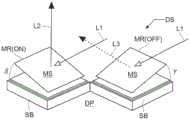
图7是表示数字微镜器件DP的微镜MR的基准状态、ON状态以及OFF状态的立体图。图8是用于对数字微镜器件DP的动作进行说明的立体图。数字微镜器件DP具有配置成矩阵状的俯视时为大致正方形的多个微小的微镜MR。微镜MR安装在基板SB上,基板SB被收纳于大致矩形的壳体(未图示)。7 is a perspective view showing a reference state, an ON state, and an OFF state of the micromirror MR of the digital micromirror device DP. FIG. 8 is a perspective view for explaining the operation of the digital micromirror device DP. The digital micromirror device DP has a plurality of micromirrors MR which are arranged in a matrix and are substantially square in plan view. The micromirror MR is mounted on the substrate SB, and the substrate SB is accommodated in a substantially rectangular case (not shown).
由基准平面MS1示出微镜MR的基准状态,由反射面MS2示出微镜MR的ON状态,由反射面MS3示出微镜MR的OFF状态。微镜MR能够在从基准状态相对于第一轴ax1倾斜后相对于与第一轴ax1正交的第二轴ax2转动。由此,数字微镜器件DP在由多个像素反射面MS构成的图像显示面DS中,对各像素反射面MS进行ON/OFF控制,从而微镜MR取得图像显示状态(ON状态)和图像非显示状态(OFF状态)这2个角度状态。即,数字微镜器件DP对于正交的2轴进行微镜MR的驱动,微镜MR能够取得基准状态、ON状态以及OFF状态。由此,数字微镜器件DP构成对照明光L1进行强度调制来生成所希望的图像的反射型图像显示元件。即,数字微镜器件DP对照明光L1进行强度调制来生成投影光。The reference state of the micromirror MR is shown by the reference plane MS1, the ON state of the micromirror MR is shown by the reflection surface MS2, and the OFF state of the micromirror MR is shown by the reflection surface MS3. The micromirror MR can be rotated with respect to the second axis ax2 orthogonal to the first axis ax1 after being inclined with respect to the first axis ax1 from the reference state. As a result, the digital micromirror device DP performs ON/OFF control on each pixel reflection surface MS in the image display surface DS composed of a plurality of pixel reflection surfaces MS, so that the micromirror MR obtains the image display state (ON state) and the image display state (ON state) The two angle states are the non-display state (OFF state). That is, the digital micromirror device DP drives the micromirror MR with respect to two orthogonal axes, and the micromirror MR can acquire a reference state, an ON state, and an OFF state. Thereby, the digital micromirror device DP constitutes a reflective image display element that generates a desired image by modulating the intensity of the illumination light L1. That is, the digital micromirror device DP generates projection light by intensity-modulating the illumination light L1.
由于各微镜MR的驱动对于正交的2轴(第一轴ax1、第二轴ax2)进行,所以微镜MR的像素反射面MS在不同的面内倾斜。在本实施方式的数字微镜器件DP2中,在YZ平面内倾斜的状态为ON状态,在XZ平面内倾斜的状态为OFF状态。在通常假定的ON/OFF控制中,在像素反射面MS为ON状态时,入射到微镜MR的照明光L1被向图像显示面DS的法线(数字微镜器件DP的法线)方向反射而成为ON光L2(投影光)。另外,在像素反射面MS为OFF状态时,入射到微镜MR的照明光L1被与图像显示面DS的法线方向成较大的角度地反射,成为OFF光L3(无效光)。Since the driving of each micromirror MR is performed on two orthogonal axes (the first axis ax1 and the second axis ax2 ), the pixel reflection surfaces MS of the micromirrors MR are inclined in different planes. In the digital micromirror device DP2 of the present embodiment, the state inclined in the YZ plane is the ON state, and the state inclined in the XZ plane is the OFF state. In the normally assumed ON/OFF control, when the pixel reflection surface MS is in the ON state, the illumination light L1 incident on the micromirror MR is reflected in the direction of the normal line of the image display surface DS (the normal line of the digital micromirror device DP) Instead, it becomes ON light L2 (projection light). In addition, when the pixel reflection surface MS is in the OFF state, the illumination light L1 incident on the micromirror MR is reflected at a large angle to the normal direction of the image display surface DS, and becomes OFF light L3 (ineffective light).
因此,如图9所示,在数字微镜器件DP2的附近,各微镜MR将OFF光L3向OFF光L3的光轴AX3远离包括ON光L2的光轴AX2和照明光L1的光轴AX1的光轴平面AP的方向反射。另外,图像显示面DS的法线(数字微镜器件DP的法线)与数字微镜器件DP2的附近的ON光L2(投影光)的光轴AX2平行。此外,在数字微镜器件DP1、DP3的附近也与数字微镜器件DP2相同地,各微镜MR将OFF光L3向远离包括光轴AX1、AX2的平面(未图示)的方向反射。Therefore, as shown in FIG. 9 , in the vicinity of the digital micromirror device DP2, each micromirror MR moves the OFF light L3 to the optical axis AX3 of the OFF light L3 away from the optical axis AX2 including the optical axis AX2 of the ON light L2 and the optical axis AX1 of the illumination light L1 is reflected in the direction of the optical axis plane AP. In addition, the normal line of the image display surface DS (the normal line of the digital micromirror device DP) is parallel to the optical axis AX2 of the ON light L2 (projection light) in the vicinity of the digital micromirror device DP2. Also in the vicinity of the digital micromirror devices DP1 and DP3 , like the digital micromirror device DP2 , each micromirror MR reflects the OFF light L3 in a direction away from a plane (not shown) including the optical axes AX1 and AX2 .
在本实施方式中,ON状态的微镜MR的法线与数字微镜器件DP的法线所成的角度β为17°,OFF状态的微镜MR的法线与数字微镜器件DP的法线所成的角度γ为17°。因此,数字微镜器件DP的入射光(照明光L1)的光轴AX1与数字微镜器件DP的法线所成的角度为34°。In this embodiment, the angle β formed by the normal line of the micromirror MR in the ON state and the normal line of the digital micromirror device DP is 17°, and the normal line of the micromirror MR in the OFF state and the normal line of the digital micromirror device DP are 17°. The angle γ formed by the lines is 17°. Therefore, the angle formed by the optical axis AX1 of the incident light (illumination light L1 ) of the digital micromirror device DP and the normal line of the digital micromirror device DP is 34°.
如以上所述,在数字微镜器件DP的图像显示面DS中,通过照明光L1的强度调制来形成二维图像。数字微镜器件DP通过如上述那样对于正交的2轴进行微镜MR的驱动来表现ON/OFF。As described above, in the image display surface DS of the digital micromirror device DP, a two-dimensional image is formed by the intensity modulation of the illumination light L1. The digital micromirror device DP expresses ON/OFF by driving the micromirrors MR with respect to the two orthogonal axes as described above.
返回图2~图6,对内部全反射棱镜P1、颜色分解合成棱镜单元P2、投影侧棱镜P3以及OFF光分离棱镜P4进行说明。内部全反射棱镜P1具有入射面11、照明光反射面12以及出射面13(参照图3)。入射面11向随着朝向屏幕SC而接近投影光学系统LN的方向倾斜,入射从照明光学系统2出射的照明光L1。Returning to FIGS. 2 to 6 , the total internal reflection prism P1 , the color separation and synthesis prism unit P2 , the projection side prism P3 , and the OFF light separation prism P4 will be described. The total internal reflection prism P1 has an
照明光反射面12由形成于内部全反射棱镜P1的全反射面构成,向随着远离入射面11而接近颜色分解合成棱镜单元P2的方向倾斜。照明光反射面12将从入射面11入射的照明光L1朝向颜色分解合成棱镜单元P2全反射。The illumination
出射面13与颜色分解合成棱镜单元P2对置地配置,向随着朝向入射面11而远离投影光学系统LN的方向倾斜。出射面13将由照明光反射面12全反射的照明光L1朝向颜色分解合成棱镜单元P2射出。The
具有棱镜P21、P22、P23的颜色分解合成棱镜单元P2是所谓的菲利普斯型(philips型)的二向色棱镜单元,从内部全反射棱镜P1朝向数字微镜器件DP2依次配置棱镜P21、P23、P22。The color decomposition and synthesis prism unit P2 having the prisms P21, P22, and P23 is a so-called philips type dichroic prism unit, and the prisms P21, P23, P22.
棱镜P21、P22、P23分别具有入射出射面21a、22a、23a。入射出射面21a、22a、23a分别与OFF光分离棱镜P4接近并对置。入射出射面21a、22a、23a分别向随着朝向后述的OFF光出射面43而分别远离数字微镜器件DP1、DP2、DP3的方向倾斜。The prisms P21, P22, and P23 have incident and
另外,在颜色分解合成棱镜单元P2中,配置于最靠射出侧(最靠投影光学系统LN侧)的棱镜P21的射出侧的入射出射面21b(第一面)向随着朝向内部全反射棱镜P1的入射面11侧而远离投影光学系统LN的方向倾斜。在本实施方式中,入射出射面21b相对于XY平面倾斜约11°。In addition, in the color separation and synthesis prism unit P2, the incident and
入射到照明光反射面12的照明光L1的入射光L11的光轴AX1和ON光L2(投影光)的入射出射面21b上的光轴AX2被配置在作为同一平面的光轴平面AP(参照图9)上。光轴平面AP与图6的纸面为同一平面。将入射出射面21b的向外的第一法向矢量NV1(参照图2)投影到光轴平面AP而相对于ON光L2的光轴AX2配置在与入射光L11的光轴AX1相同侧的第一分量矢量CV1朝向随着远离入射出射面21b而远离从入射出射面21b射出的ON光L2的光轴AX2的方向。The optical axis AX1 of the incident light L11 of the illumination light L1 incident on the illumination
另外,棱镜P21、P23分别在内部具有全反射面21t、23t,并且分别在内部具有二向色涂层面DR以及二向色涂层面DB。全反射面21t由入射出射面21b的内侧的面构成。二向色涂层面DR与全反射面21t对置地配置,全反射面23t与二向色涂层面DR接近地对置配置。二向色涂层面DB与棱镜P22接近地对置配置。In addition, the prisms P21 and P23 have total reflection surfaces 21t and 23t inside, respectively, and have a dichroic coating surface DR and a dichroic coating surface DB respectively inside. 21 t of total reflection surfaces are comprised by the surface inside the incident-
如图4所示,二向色涂层面DR以及全反射面23t从Y方向来看向随着远离数字微镜器件DP1而接近投影光学系统LN的方向倾斜。二向色涂层面DB从Y方向来看向随着远离数字微镜器件DP3而接近投影光学系统LN的方向倾斜。入射出射面21b以及全反射面21t从Y方向来看与数字微镜器件DP2的法线垂直。即,入射出射面21b以及全反射面21t从Y方向来看与由数字微镜器件DP2反射的ON光L2的光轴AX2垂直。As shown in FIG. 4 , the dichroic coating surface DR and the
另外,将与入射出射面21b对置的二向色涂层面DR(对置面)的向内的第二法向矢量NV2(参照图4)投影到光轴平面AP而相对于ON光L2的光轴AX2配置在与入射光L11的光轴AX1相同侧的第二分量矢量CV2(参照图6)朝向随着远离二向色涂层面DR而远离从入射出射面21b出射的ON光L2的光轴AX2的方向。In addition, the inward second normal vector NV2 (refer to FIG. 4 ) of the dichroic coating surface DR (opposing surface) facing the incident and
另外,将二向色涂层面DB的向内的第三法向矢量NV3(参照图4)投影到光轴平面AP而相对于ON光L2的光轴AX2配置在与入射光L11的光轴AX1相同侧的第三分量矢量CV3(参照图6)朝向随着远离二向色涂层面DB而远离从入射出射面21b出射的ON光L2的光轴AX2的方向。In addition, the inward third normal vector NV3 (refer to FIG. 4 ) of the dichroic coating surface DB is projected on the optical axis plane AP and arranged on the optical axis of the incident light L11 with respect to the optical axis AX2 of the ON light L2 The third component vector CV3 (refer to FIG. 6 ) on the same side as AX1 is oriented in a direction away from the optical axis AX2 of the ON light L2 emitted from the incident and
二向色涂层面DR反射照明光L1的红色成分,并且使照明光L1的绿色成分以及蓝色成分透过。二向色涂层面DB反射照明光L1的蓝色成分并且使照明光L1的绿色成分透过。即,二向色涂层面DR以及二向色涂层面DB反射规定波长的照明光L1的成分并透过该规定波长以外的照明光L1的成分。由此,颜色分解合成棱镜单元P2对从内部全反射棱镜P1出射的照明光L1进行颜色分解并分别向数字微镜器件DP侧出射。The dichroic coating surface DR reflects the red component of the illumination light L1, and transmits the green component and the blue component of the illumination light L1. The dichroic coating surface DB reflects the blue component of the illumination light L1 and transmits the green component of the illumination light L1. That is, the dichroic coating surface DR and the dichroic coating surface DB reflect the components of the illumination light L1 of predetermined wavelengths, and transmit the components of the illumination light L1 other than the predetermined wavelengths. As a result, the color separation and synthesis prism unit P2 performs color separation on the illumination light L1 emitted from the total internal reflection prism P1 and emits it to the side of the digital micromirror device DP, respectively.
另外,二向色涂层面DR反射红色的ON光L2,并且使绿色以及蓝色的ON光L2透过。二向色涂层面DB反射蓝色的ON光L2并且使绿色的ON光L2透过。即,二向色涂层面DR以及二向色涂层面DB反射规定波长的ON光L2并透过该规定波长以外的ON光L2。由此,颜色分解合成棱镜单元P2对从数字微镜器件DP1、DP2、DP3分别出射的红色、绿色以及蓝色的ON光L2进行颜色合成并经由入射出射面21b向射出侧出射。In addition, the dichroic coating surface DR reflects red ON light L2 and transmits green and blue ON light L2. The dichroic coating surface DB reflects blue ON light L2 and transmits green ON light L2. That is, the dichroic coating surface DR and the dichroic coating surface DB reflect ON light L2 of a predetermined wavelength and transmit ON light L2 other than the predetermined wavelength. Thus, the color decomposition and synthesis prism unit P2 performs color synthesis on the red, green and blue ON lights L2 emitted from the digital micromirror devices DP1, DP2 and DP3, respectively, and emits them to the output side through the incidence and
此外,也可以替换配置棱镜P21和棱镜P23。即,也可以将棱镜P23配置在比棱镜P21靠射出侧。另外,也可以代替所谓的菲利普斯型的二向色棱镜单元,而通过十字分色棱镜单元来形成颜色分解合成棱镜单元P2。In addition, the prism P21 and the prism P23 may be alternately arranged. That is, the prism P23 may be arranged on the emission side rather than the prism P21. In addition, instead of the so-called Phillips-type dichroic prism unit, the color separation and synthesis prism unit P2 may be formed by a cross dichroic prism unit.
投影侧棱镜P3(射出侧光学部件)被配置在颜色分解合成棱镜单元P2的棱镜P21的出射侧(射出侧)且内部全反射棱镜P1的入射面11的相反侧(在图2中为上方),具有入射面31以及出射面32(第二面、射出面)。此外,“射出面”是指ON光L2朝向投影光学系统LN从光学单元PU射出的面。入射面31从X方向来看向随着远离内部全反射棱镜P1而接近投影光学系统LN的方向倾斜。入射面31被入射从入射出射面21b出射的ON光L2(颜色合成后的投影光)。The projection-side prism P3 (exit-side optical component) is arranged on the exit side (exit side) of the prism P21 of the color separation and synthesis prism unit P2 and on the opposite side (upper side in FIG. 2 ) of the
出射面32与投影光学系统LN对置地配置,以使ON光L2的光轴AX2与出射面32的法线方向一致的方式射出ON光L2。能够减少通过投影侧棱镜P3投影到屏幕SC的图像的失真。另外,内部全反射棱镜P1的投影光学系统LN侧的端部相对于投影侧棱镜P3的出射面32向射出方向(Z方向)突出。The
各OFF光分离棱镜P4分别与入射出射面21a、22a、23a接近地对置配置。各OFF光分离棱镜P4具有入射出射面41、OFF光反射面42以及OFF光出射面43。各入射出射面41分别与数字微镜器件DP1、DP2、DP3接近地对置配置,数字微镜器件DP1、DP2、DP3的附近的ON光L2的光轴AX2分别与入射出射面41的法线方向一致。Each of the OFF light separation prisms P4 is arranged so as to be close to the incident and
OFF光出射面43由相对于ON光L2的光轴AX2与内部全反射棱镜P1的入射面11相反侧的端面(Y方向的端面,图2中为上表面)构成。配置在数字微镜器件DP1、DP2、DP3的各个的附近的各OFF光反射面42倾斜为越朝向OFF光出射面43,越分别远离数字微镜器件DP1、DP2、DP3。OFF光反射面42将由OFF状态的微镜MR反射的OFF光L3全反射并且使由ON状态的微镜MR反射的ON光L2透过。OFF光出射面43将由OFF光反射面42全反射的OFF光L3朝向光学单元PU的外部出射。The OFF
另外,与各OFF光出射面43分离并对置地设置有光吸收部件PM。光吸收部件PM例如由进行黑色处理后的金属板形成,吸收从OFF光出射面43出射的OFF光L3。由此,能够防止由从光学单元PU出射的OFF光L3引起的投影仪PJ内的其他部件等的热变形。Moreover, the light absorption member PM is provided so that it may be spaced apart from each OFF
另外,在内部全反射棱镜P1与颜色分解合成棱镜单元P2之间、颜色分解合成棱镜单元P2与投影侧棱镜P3之间、颜色分解合成棱镜单元P2与OFF光分离棱镜P4之间设置有空气层(空气间隙,未图示)。另外,在颜色分解合成棱镜单元P2中,在棱镜P21与棱镜23之间、棱镜P23与棱镜22之间也设置有空气层。In addition, an air layer is provided between the total internal reflection prism P1 and the color separation and synthesis prism unit P2, between the color separation and synthesis prism unit P2 and the projection side prism P3, and between the color separation and synthesis prism unit P2 and the OFF light separation prism P4 (air gap, not shown). In addition, in the color separation and synthesis prism unit P2 , an air layer is also provided between the prism P21 and the
在上述结构的投影仪PJ中,若从光源1(参照图1)出射白光,则由照明光学系统2(参照图1)聚光并将白色的照明光L1朝向光学单元PU出射。In the projector PJ having the above-described configuration, when white light is emitted from the light source 1 (see FIG. 1 ), the illumination optical system 2 (see FIG. 1 ) condenses and emits the white illumination light L1 toward the optical unit PU.
白色的照明光L1在入射到内部全反射棱镜P1的入射面11后由照明光反射面12全反射。由照明光反射面12全反射的白色的照明光L1从出射面13出射后,入射到颜色分解合成棱镜单元P2的棱镜21的入射出射面21b。The white illumination light L1 is incident on the
入射到颜色分解合成棱镜单元P2的棱镜P21的白色的照明光L1入射至二向色涂层面DR,照明光L1的红色成分被反射并且绿色成分以及蓝色成分透过。透过了二向色涂层面DR的照明光L1的绿色成分以及蓝色成分入射至棱镜P23,蓝色成分被二向色涂层面DB反射并且绿色成分透过二向色涂层面DB后入射至棱镜P22。The white illumination light L1 incident on the prism P21 of the color separation and synthesis prism unit P2 is incident on the dichroic coating surface DR, the red component of the illumination light L1 is reflected, and the green component and the blue component are transmitted. The green component and the blue component of the illumination light L1 transmitted through the dichroic coating surface DR are incident on the prism P23, the blue component is reflected by the dichroic coating surface DB, and the green component is transmitted through the dichroic coating surface DB It is then incident on the prism P22.
由二向色涂层面DR反射的照明光L1的红色成分、由二向色涂层面DB反射的照明光L1的蓝色成分以及透过了二向色涂层面DR、DB的照明光L1的绿色成分分别从入射出射面21a、23a、22a出射,分别入射到OFF光分离棱镜P4。透过了各OFF光分离棱镜P4的照明光L1的红色成分、绿色成分以及蓝色成分从入射出射面41出射,并分别透过盖玻璃CG而入射到数字微镜器件DP1、DP3、DP2。由此,颜色分解合成棱镜单元P2对由照明光反射面12全反射后的照明光L1进行颜色分解并分别向数字微镜器件DP1、DP2、DP3侧出射。The red component of the illumination light L1 reflected by the dichroic coating surface DR, the blue component of the illumination light L1 reflected by the dichroic coating surface DB, and the illumination light transmitted through the dichroic coating surfaces DR, DB The green components of L1 are emitted from the incident and emitting
由数字微镜器件DP1~DP3的ON状态的微镜MR分别反射的红色、绿色以及蓝色的ON光L2分别从入射出射面41入射到OFF光分离棱镜P4,透过OFF光反射面42分别从入射出射面21a、22a、23a入射到颜色分解合成棱镜单元P2的棱镜P21、P22、P23。The red, green, and blue ON lights L2 reflected by the ON-state micromirrors MR of the digital micromirror devices DP1 to DP3 respectively enter the OFF light separation prism P4 from the incident and exit surfaces 41, and pass through the OFF
红色的ON光L2在由棱镜P21的全反射面21t全反射后由二向色涂层面DR反射而朝向入射出射面21b。绿色的ON光L2透过棱镜P22后依次透过二向色涂层面DB、DR而朝向入射出射面21b。蓝色的ON光L2在由棱镜P23的全反射面23t全反射后由二向色涂层面DB反射,透过二向色涂层面DR而朝向入射出射面21b。此时,红色、绿色以及蓝色的ON光L2在透过颜色分解合成棱镜单元P2的期间进行颜色合成,颜色合成后的ON光L2从入射出射面21b向射出侧出射。The red ON light L2 is totally reflected by the
从入射出射面21b出射的ON光L2(颜色合成后的投影光)经由入射面31入射到投影侧棱镜P3。入射到投影侧棱镜P3的ON光L2透过投影侧棱镜P3从出射面32朝向投影光学系统LN射出。The ON light L2 (projection light after color synthesis) emitted from the incidence and
此时,如图6所示,照明光反射面12配置在ON光L2的光束的外侧。即,ON光L2不入射到照明光反射面12。由此,能够在与数字微镜器件DP2对应的OFF光分离棱镜P4的入射出射面41与出射面32之间的Z方向的距离D1(在本实施方式中约为85mm)内将照明光L1的光束和ON光L2的光束分离。At this time, as shown in FIG. 6, the illumination
另外,照明光反射面12上的照明光L1的光束的颜色分解合成棱镜单元P2侧的端部相对于出射面32配置在与颜色分解合成棱镜单元P2相同侧。即,照明光反射面12上的照明光L1的光束投影于光轴平面AP的区域的颜色分解合成棱镜单元P2侧的端部LE(参照图6)相对于出射面32配置在与颜色分解合成棱镜单元P2相同侧。另外,照明光反射面12与出射面32的交线NL配置在比出射面32上的ON光L2的光束靠外侧。由此,出射面32上的ON光L2的光束和照明光反射面12上的照明光L1的光束不重叠。此外,“照明光反射面12与出射面32的交线NL”表示包括出射面32且与出射面32平行的面与照明光反射面12的交线。In addition, the end of the light beam of the illumination light L1 on the illumination
另外,包括从入射出射面21b出射的ON光L2的光轴AX2并且穿过数字微镜器件DP2的长边方向中央并与其短边方向平行的平面(在本实施方式中,与光轴平面AP相同的平面)与照明光反射面12正交。In addition, a plane including the optical axis AX2 of the ON light L2 emitted from the incident and
入射到投影光学系统LN的ON光L2被投射到屏幕SC(参照图1)。由此,显示于数字微镜器件DP的彩色图像被投影到屏幕SC。此时,通过促动器4进行缩放或聚焦。另外,投影侧棱镜P3以光轴AX2与出射面32的法线方向一致的方式将ON光L2从出射面32射出。由此,能够减少放大投影到屏幕SC的图像的失真。The ON light L2 incident on the projection optical system LN is projected on the screen SC (see FIG. 1 ). Thereby, the color image displayed on the digital micromirror device DP is projected on the screen SC. At this time, zooming or focusing is performed by the actuator 4 . In addition, the projection-side prism P3 emits the ON light L2 from the
另外,通过促动器4使投影光学系统LN的投影透镜51、52在Y方向上移动,能够在Y方向上变更投影图像的投影位置。例如,在投影仪PJ安装于起居室(未图示)内的天花板表面的情况下,使投影透镜51、52向内部全反射棱镜P1侧(在图5中为下方)移动。由此,投影仪PJ能够将图像投影到在屏幕SC上远离天花板的位置。In addition, by moving the
此时,第一分量矢量CV1朝向随着远离入射出射面21b而远离从入射出射面21b出射的ON光L2的光轴AX2的方向。由此,即使增大ON光L2的出射面32上的光轴AX2与交线NL之间的距离D2,也能够使朝向内部全反射棱镜P1的照明光L1的光束中的颜色分解合成棱镜单元P2侧的照明光L1的光线也入射到入射面11,能够由照明光反射面12全反射。At this time, the first component vector CV1 is oriented in a direction away from the optical axis AX2 of the ON light L2 emitted from the incidence and
另一方面,由数字微镜器件DP1、DP2、DP3的OFF状态的微镜MR反射的OFF光L3在从入射出射面41入射到OFF光分离棱镜P4之后由OFF光反射面42全反射,并从OFF光出射面43向光学单元PU的外部排出。而且,从光学单元PU排出的OFF光L3被光吸收部件PM吸收。由此,能够防止OFF光L3向投影光学系统LN的入射。因此,能够防止投影图像的对比度的降低。On the other hand, the OFF light L3 reflected by the micromirrors MR in the OFF states of the digital micromirror devices DP1, DP2 and DP3 is totally reflected by the OFF
此时,光吸收部件PM与OFF光出射面43分离设置。由此,能够减少吸收了OFF光L3后的光吸收部件PM的热向光学单元PU的导热。因此,能够抑制光学单元PU的温度上升,防止光学单元PU的热变形等。其结果是,能够实现光学单元PU以及投影仪PJ的长寿命化。At this time, the light absorbing member PM is provided separately from the OFF
此外,由正在从ON状态以及OFF状态中的一方向另一方转移的微镜MR反射的照明光L1(平光)相对于微镜MR的法线方向向与照明光L1的入射光相反方向反射。平光或盖玻璃CG处的照明光L1的反射光也在入射到OFF光分离棱镜P4之后从OFF光出射面43出射。由此,能够防止平光或盖玻璃CG处的照明光L1的反射光向投影光学系统LN的入射。因此,能够进一步防止投影图像的对比度的降低。In addition, the illumination light L1 (flat light) reflected by the micromirror MR that is transitioning from one of the ON state and the OFF state to the other is reflected in a direction opposite to the incident light of the illumination light L1 with respect to the normal direction of the micromirror MR. The flat light or the reflected light of the illumination light L1 at the cover glass CG is also emitted from the OFF
这里,若在各OFF光分离棱镜P4中,向OFF光反射面42的入射角度最大的ON光L2的光线的向OFF光反射面42的入射角度θON和向OFF光反射面42的入射角度最小的OFF光L3的光线的向OFF光反射面42的入射角度θOFF满足以下的条件式(1),则因OFF光反射面42能够使ON光L2透过并将OFF光L3几乎全反射而优选。Here, in each OFF light splitting prism P4, the incident angle θON of the ON light L2 having the largest incident angle to the OFF
θOFF>sin-1(1/n)>θON···(1)θOFF > sin-1 (1/n) > θON ...(1)
其中,in,
θON:向OFF光反射面42的入射角度最大的ON光L2的光线的向OFF光反射面42的入射角度,θON : the incident angle to the OFF
θOFF:向OFF光反射面42的入射角度最小的OFF光L2的光线的向OFF光反射面42的入射角度,θOFF : the incident angle to the OFF
n:OFF光分离棱镜P4的折射率。n: Refractive index of the OFF light splitting prism P4.
例如,在将OFF光分离棱镜P4的折射率n设为1.5168的情况下,若使入射角度θON为36.5°并且使入射角度θOFF为43.7°,则满足条件式(1),OFF光反射面42能够使ON光L2透过并将OFF光L3几乎全反射。For example, when the refractive index n of the OFF light splitting prism P4 is set to 1.5168, if the incident angle θON is set to 36.5° and the incident angle θOFF is set to 43.7°, the conditional expression (1) is satisfied and the OFF light is reflected. The
对于使用了本实施方式的光学单元PU的投影仪PJ以及使用了比较例的光学单元的投影仪,比较了投影光学系统LN的上下移位量(Y方向的移位量)。The vertical displacement amount (the displacement amount in the Y direction) of the projection optical system LN was compared between the projector PJ using the optical unit PU of the present embodiment and the projector using the optical unit of the comparative example.
图10示出比较例的光学单元的侧剖视图。为了方便说明,对与本实施方式的光学单元PU相同的部分标注相同的附图标记。在比较例中,颜色分解合成棱镜单元P2的棱镜P21的入射出射面21b与颜色合成后的ON光L2的光轴AX2垂直。另外,在比较例中省略投影侧棱镜P3。因此,本实施方式的射出面与投影侧棱镜P3的出射面32一致,比较例的射出面与棱镜P21的入射出射面21b一致。比较例的其他的构成与本实施方式的光学单元PU相同。另外,上下移位量设为射出面上的ON光L2的光轴AX2与交线NL之间的距离D2(参照图6、图10)。此外,与数字微镜器件DP2对置的入射出射面41与出射面32之间的Z方向的距离D1在本实施方式以及比较例中为85mm。另外,本实施方式以及比较例的照明光反射面12相对于XZ平面的倾斜角度相同。FIG. 10 shows a side cross-sectional view of an optical unit of a comparative example. For convenience of description, the same reference numerals are assigned to the same parts as those of the optical unit PU of the present embodiment. In the comparative example, the incident and
相对于本实施方式的投影仪PJ的投影光学系统LN的上下移位量是26.6mm,而比较例的投影仪的投影光学系统的上下移位量是19.0mm。因此,使用了本实施方式的光学单元PU的情况下的上下移位量比比较例长7.6mm。因此,能够使具备本实施方式的光学单元PU的投影仪PJ的投影光学系统LN的上下移位量比比较例的情况长。此外,在本实施方式以及比较例中,照明光L1的F数大致相同,投影图像的亮度也大致相同。The vertical displacement amount with respect to the projection optical system LN of the projector PJ of the present embodiment is 26.6 mm, and the vertical displacement amount of the projection optical system of the projector of the comparative example is 19.0 mm. Therefore, the vertical displacement amount in the case of using the optical unit PU of the present embodiment is 7.6 mm longer than that of the comparative example. Therefore, the vertical displacement amount of the projection optical system LN of the projector PJ including the optical unit PU of the present embodiment can be made longer than that in the case of the comparative example. In addition, in the present embodiment and the comparative example, the F-number of the illumination light L1 is substantially the same, and the brightness of the projected image is also substantially the same.
根据本实施方式,第一分量矢量CV1朝向随着远离入射出射面21b而远离从入射出射面21b出射的ON光L2的光轴AX2的方向,其中,以在将入射出射面21b的向外的第一法向矢量NV1投影到光轴平面AP时第一分量矢量CV1相对于ON光L2的光轴AX2配置在与入射光L11的光轴AX1相同侧的方式将第一法向矢量NV1投影到光轴平面AP。由此,即使增大ON光L2的出射面32(射出面)上的光轴AX2与交线NL之间的距离D2,也能够使朝向内部全反射棱镜P1的照明光L1的光束中的颜色分解合成棱镜单元P2侧的照明光L1的光线也入射到入射面11并由照明光反射面12全反射。因此,在配置投影光学系统LN时,能够防止射出的ON光L2(投影光)的光量的减少,并且增大投影光学系统LN的Y方向的移位量来提高光学单元PU的使用性。According to the present embodiment, the first component vector CV1 is oriented in a direction away from the optical axis AX2 of the ON light L2 exiting from the incident and
另外,棱镜P21(第一棱镜)以及棱镜P23(第一棱镜)分别具有二向色涂层面DR、DB,颜色分解合成棱镜单元P2(棱镜单元)进行照明光L1的颜色分解和ON光L2(投影光)的颜色合成。由此,能够容易地对白色的照明光进行颜色分解,并且能够容易地进行各种颜色的投影光的颜色合成。In addition, the prism P21 (first prism) and the prism P23 (first prism) have dichroic coating surfaces DR and DB, respectively, and the color decomposition and synthesis prism unit P2 (prism unit) performs color decomposition of the illumination light L1 and ON light L2 (projected light) color composition. Thereby, the color decomposition of the white illumination light can be easily performed, and the color combination of the projection lights of various colors can be easily performed.
另外,第二分量矢量CV2朝向随着远离二向色涂层面DR而远离从入射出射面21b出射的ON光L2的光轴AX2的方向,以在将具有入射出射面21b的棱镜P21(第一棱镜)的与入射出射面21b对置的二向色涂层面DR(对置面)的向内的第二法向矢量NV2投影到光轴平面AP时第二分量矢量CV2相对于光轴AX2配置在与入射光L11的光轴AX1相同侧的方式将第二法向矢量NV2投影到光轴平面AP。由此,能够使入射出射面21b倾斜并且充分确保棱镜P21的Z方向的长度,能够进一步防止引导至数字微镜器件DP的照明光L1的光量的减少。In addition, the second component vector CV2 is oriented in a direction away from the optical axis AX2 of the ON light L2 emitted from the incident and
另外,照明光反射面12被配置在ON光L2的光束的外侧。由此,能够通过与数字微镜器件DP2对置的入射出射面41与出射面32之间的Z方向的距离D1来将照明光L1的光束和ON光L2的光束分离。因此,ON光L2不透过照明光反射面12,所以与将投影侧棱镜P3与照明光反射面12接近地对置配置的构成相比较,ON光L2通过的空气层(空气间隙)的数量减少。因此,能够提高光学单元PU中的ON光L2的透过率,能够提高投影图像的画质。In addition, the illumination
另外,照明光反射面12由内部全反射棱镜P1(反射部件)的全反射面形成。由此,照明光反射面12上的照明光L1的光束的剖面小于入射到入射面11之前的照明光L1的光束的剖面,所以能够抑制照明光反射面12的大型化并且能够进一步防止ON光L2的光量的减少。另外,能够提高照明光L1在照明光反射面12处的反射效率,能够进一步防止ON光L2的光量的减少。In addition, the illumination
另外,具备投影侧棱镜P3(射出侧光学部件),该投影侧棱镜P3(射出侧光学部件)具有在法线方向配置有ON光L2(投影光)的光轴AX2并且射出ON光L2的出射面32(第二面),并且配置在入射出射面21b的ON光L2的出射方向侧。由此,能够减少投影图像的失真。而且,照明光反射面12上的照明光L1的光束的颜色分解合成棱镜单元P2(棱镜单元)侧的端部相对于出射面32配置在与颜色分解合成棱镜单元P2相同侧,照明光反射面12与出射面32的交线NL配置在比出射面32上的ON光L2的光束靠外侧。由此,能够更可靠地确保投影光学系统LN的Y方向的移位量。In addition, a projection-side prism P3 (exit-side optical member) is provided which has an optical axis AX2 on which the ON light L2 (projection light) is arranged in the normal direction, and which emits the output of the ON light L2 The surface 32 (second surface) is disposed on the exit direction side of the ON light L2 incident on the
另外,具备多个用于安装数字微镜器件DP的安装部,将各安装部分别与棱镜P21、P22、P23对应地配置。数字微镜器件DP通过对以转动轴为中心转动的多个微镜MR的各面的倾斜进行ON/OFF控制而对照明光L1进行强度调制,来形成图像。由此,能够容易地将数字微镜器件DP安装于光学单元PU,能够容易地实现能够射出由数字微镜器件DP生成的投影光的光学单元PU。In addition, a plurality of mounting portions for mounting the digital micromirror device DP are provided, and the respective mounting portions are arranged corresponding to the prisms P21, P22, and P23, respectively. The digital micromirror device DP forms an image by performing intensity modulation on the illumination light L1 by ON/OFF control of the inclination of each surface of the plurality of micromirrors MR that rotate around the rotation axis. Thereby, the digital micromirror device DP can be easily attached to the optical unit PU, and the optical unit PU capable of emitting the projection light generated by the digital micromirror device DP can be easily realized.
各微镜MR具有两根相互正交的转动轴,各微镜MR的驱动对于两根转动轴进行。由此,能够提高投影图像的亮度。而且,包括从入射出射面21b出射的ON光L2的光轴AX2并且穿过数字微镜器件DP2(一个数字微镜器件DP)的长边方向中央并与其短边方向平行的平面与照明光反射面12正交。由此,能够减小照明光L1的光束的剖面,所以能够更可靠地将照明光L1的光束引导至照明光反射面12。Each micromirror MR has two mutually orthogonal rotation axes, and each micromirror MR is driven with respect to the two rotation axes. Thereby, the brightness of the projected image can be improved. Also, a plane including the optical axis AX2 of the ON light L2 emitted from the incident and
另外,在数字微镜器件DP1、DP2、DP3与棱镜P21、P22、P23之间分别配置有OFF光分离棱镜P4(第三棱镜)。OFF光分离棱镜P4具有OFF光反射面42,该OFF光反射面42使由数字微镜器件DP的ON状态的微镜MR反射的ON光L2(投影光)透过,并且反射由数字微镜器件DP的OFF状态的微镜MR反射的OFF光L3(无效光)。由此,能够不使OFF光L3入射至颜色分解合成棱镜单元P2而排出到光学单元PU的外部。因此,能够防止OFF光L3向投影光学系统LN的投影透镜51、52的入射。其结果是,能够防止产生杂光,能够提高投影图像的对比度。In addition, an OFF light separation prism P4 (third prism) is arranged between the digital micromirror devices DP1, DP2, and DP3 and the prisms P21, P22, and P23, respectively. The OFF light splitting prism P4 has an OFF
另外,若满足条件式(1),则OFF光反射面42能够使ON光L2透过并将OFF光L3几乎全反射。In addition, if the conditional expression (1) is satisfied, the OFF
另外,投影仪PJ具备光学单元PU、光源1、将照明光L1朝向内部全反射棱镜P1(反射部件)出射的照明光学系统2、以及将显示在安装于安装部的数字微镜器件DP的图像放大投影到屏幕SC的投影光学系统LN。由此,能够容易地实现具备光学单元PU的投影仪PJ。In addition, the projector PJ includes an optical unit PU, a light source 1, an illumination
另外,投影光学系统LN与光学单元PU的入射出射面21b对置地配置,并且内部全反射棱镜P1配置在比从入射出射面21b出射的ON光L2的光轴AX2靠下方。而且,投影光学系统LN能够沿上下方向移动。由此,能够容易地实现能够上下移位的投影仪PJ。In addition, the projection optical system LN is arranged to face the entrance/
<第二实施方式><Second Embodiment>
接下来,对本发明的第二实施方式进行说明。图11~图14分别示出第二实施方式的光学单元PU的立体图、顶视图、侧视图以及侧剖视图。为了方便说明,对与图1~图9所示的第一实施方式相同的部分标注同一附图标记。在本实施方式中,颜色分解合成棱镜单元P2的入射出射面21b(第一面)的构成与第一实施方式不同。其他的部分与第一实施方式相同。Next, a second embodiment of the present invention will be described. 11 to 14 show a perspective view, a top view, a side view, and a side sectional view of the optical unit PU according to the second embodiment, respectively. For convenience of description, the same reference numerals are assigned to the same parts as those of the first embodiment shown in FIGS. 1 to 9 . In the present embodiment, the configuration of the incident and exit surfaces 21b (first surfaces) of the color separation and synthesis prism unit P2 is different from that of the first embodiment. Other parts are the same as in the first embodiment.
本实施方式的颜色分解合成棱镜单元P2的棱镜P21的入射出射面21b从Y方向来看,向随着远离数字微镜器件DP1而远离投影光学系统LN的方向倾斜。另外,投影侧棱镜P3从Y方向来看成为三角形形状。The incident and
此外,具备上述构成的光学单元PU的投影仪PJ的动作与第一实施方式相同。In addition, the operation of the projector PJ provided with the optical unit PU of the above-described configuration is the same as that of the first embodiment.
对于使用了本实施方式的光学单元PU的投影仪PJ以及使用了比较例的光学单元的投影仪,比较了投影光学系统LN的上下移位量(Y方向的移位量)。在比较例中,与图10相同地,第一分量矢量CV1与从入射出射面21b出射的ON光L2的光轴AX2平行。另外,本实施方式以及比较例的射出面与投影侧棱镜P3的出射面32一致。比较例的其他的构成与本实施方式的光学单元PU相同。另外,上下移位量的测量与第一实施方式的情况相同。此外,与数字微镜器件DP2对置的入射出射面41与出射面32之间的Z方向的距离D1在本实施方式以及比较例中为85mm。另外,本实施方式以及比较例的照明光反射面12的相对于XZ平面的倾斜角度相同。The vertical displacement amount (the displacement amount in the Y direction) of the projection optical system LN was compared between the projector PJ using the optical unit PU of the present embodiment and the projector using the optical unit of the comparative example. In the comparative example, as in FIG. 10 , the first component vector CV1 is parallel to the optical axis AX2 of the ON light L2 emitted from the incidence and
相对于使用了本实施方式的光学单元PU的投影仪PJ的投影光学系统LN的上下移位量是31.5mm,使用了比较例的光学单元的投影仪的投影光学系统的上下移位量是27.6mm。因此,使用了本实施方式的光学单元PU的情况下的上下移位量比比较例长3.9mm。因此,能够使具备本实施方式的光学单元PU的投影仪PJ的投影光学系统LN的上下移位量比比较例的情况长。此外,在本实施方式以及比较例中,照明光L1的F数大致相同,投影图像的亮度也大致相同。The vertical displacement amount of the projection optical system LN of the projector PJ using the optical unit PU of the present embodiment is 31.5 mm, and the vertical displacement amount of the projection optical system of the projector using the optical unit of the comparative example is 27.6 mm. mm. Therefore, the vertical displacement amount in the case of using the optical unit PU of the present embodiment is 3.9 mm longer than that of the comparative example. Therefore, the vertical displacement amount of the projection optical system LN of the projector PJ including the optical unit PU of the present embodiment can be made longer than that in the case of the comparative example. In addition, in the present embodiment and the comparative example, the F-number of the illumination light L1 is substantially the same, and the brightness of the projected image is also substantially the same.
在本实施方式中,也能够得到与第一实施方式相同的效果。Also in this embodiment, the same effects as those of the first embodiment can be obtained.
<第三实施方式><Third Embodiment>
接下来,对本发明的第三实施方式进行说明。图15~图18分别示出第三实施方式的光学单元PU的立体图、顶视图、侧视图以及侧剖视图。为了方便说明,对与图1~图9所示的第一实施方式相同的部分标注同一附图标记。在本实施方式中颜色分解合成棱镜单元P2的构成与第一实施方式不同。其他的部分与第一实施方式相同。Next, a third embodiment of the present invention will be described. 15 to 18 show a perspective view, a top view, a side view, and a side sectional view of the optical unit PU according to the third embodiment, respectively. For convenience of description, the same reference numerals are assigned to the same parts as those of the first embodiment shown in FIGS. 1 to 9 . The configuration of the color separation and synthesis prism unit P2 in this embodiment is different from that of the first embodiment. Other parts are the same as in the first embodiment.
本实施方式的颜色分解合成棱镜单元P2由棱镜P21、P22构成,相对于第一实施方式的颜色分解合成棱镜单元P2省略了棱镜P23。另外,也省略了与棱镜P23对应的数字微镜器件DP3。光源1由UHP灯构成,在光源1与照明光学系统2之间配置有色轮(未图示)。The color separation and synthesis prism unit P2 of the present embodiment is composed of prisms P21 and P22, and the prism P23 is omitted from the color separation and synthesis prism unit P2 of the first embodiment. In addition, the digital micromirror device DP3 corresponding to the prism P23 is also omitted. The light source 1 is composed of a UHP lamp, and a color wheel (not shown) is arranged between the light source 1 and the illumination
具备上述构成的光学单元PU的投影仪PJ的动作在照明光L1入射到入射面11后与第一实施方式相同。此外,在本实施方式中,向数字微镜器件DP1入射有照明光L1的红色成分,向数字微镜器件DP2交替地入射有通过了色轮后的照明光L1的绿色成分和蓝色成分。The operation of the projector PJ including the optical unit PU having the above-described configuration is the same as that of the first embodiment after the illumination light L1 is incident on the
对于使用了本实施方式的光学单元PU的投影仪PJ以及使用了比较例的光学单元的投影仪,比较了投影光学系统LN的上下移位量(Y方向的移位量)。在比较例中,与图10所示的构成相同地,颜色分解合成棱镜单元P2的棱镜P21的入射出射面21b与颜色合成后的ON光L2的光轴AX2垂直。另外,在比较例中省略投影侧棱镜P3。因此,本实施方式的射出面与投影侧棱镜P3的出射面32一致,比较例的射出面与棱镜P21的入射出射面21b一致。比较例的其他的构成与本实施方式的光学单元PU相同。另外,上下移位量的测量与第一实施方式的情况相同。此外,与数字微镜器件DP2对置的入射出射面41与出射面32之间的Z方向的距离D1在本实施方式以及比较例中为85mm。另外,本实施方式以及比较例的照明光反射面12的相对于XZ平面的倾斜角度相同。The vertical displacement amount (the displacement amount in the Y direction) of the projection optical system LN was compared between the projector PJ using the optical unit PU of the present embodiment and the projector using the optical unit of the comparative example. In the comparative example, as in the configuration shown in FIG. 10 , the incident and exit surfaces 21 b of the prisms P21 of the color separation and synthesis prism unit P2 are perpendicular to the optical axis AX2 of the color-combined ON light L2 . In addition, in the comparative example, the projection-side prism P3 is omitted. Therefore, the exit surface of the present embodiment corresponds to the
相对于使用了本实施方式的光学单元PU的投影仪PJ的投影光学系统LN的上下移位量是30.5mm,使用了比较例的光学单元的投影仪的投影光学系统的上下移位量是19.0mm。因此,使用了本实施方式的光学单元PU的情况下的上下移位量比比较例长11.5mm。因此,能够使具备本实施方式的光学单元PU的投影仪PJ的投影光学系统LN的上下移位量比比较例的情况长。此外,在本实施方式以及比较例中照明光L1的F数大致相同,投影图像的亮度也大致相同。The vertical displacement amount of the projection optical system LN of the projector PJ using the optical unit PU of the present embodiment is 30.5 mm, and the vertical displacement amount of the projection optical system of the projector using the optical unit of the comparative example is 19.0 mm. mm. Therefore, the vertical displacement amount in the case of using the optical unit PU of the present embodiment is 11.5 mm longer than that of the comparative example. Therefore, the vertical displacement amount of the projection optical system LN of the projector PJ including the optical unit PU of the present embodiment can be made longer than that in the case of the comparative example. In addition, in the present embodiment and the comparative example, the F-number of the illumination light L1 is substantially the same, and the brightness of the projected image is also substantially the same.
在本实施方式中,也能够得到与第一实施方式相同的效果。另外,能够与第一实施方式相比减少昂贵的数字微镜器件DP的数量。Also in this embodiment, the same effects as those of the first embodiment can be obtained. In addition, the number of expensive digital micromirror devices DP can be reduced as compared with the first embodiment.
<第四实施方式><Fourth Embodiment>
接下来对本发明的第四实施方式进行说明。图19~图21示出第四实施方式的光学单元PU的立体图、侧视图以及侧剖视图。为了方便说明,对与图1~图9所示的第一实施方式相同的部分标注同一附图标记。在本实施方式中,照明光反射面12的构成与第一实施方式不同。其他的部分与第一实施方式相同。Next, a fourth embodiment of the present invention will be described. 19 to 21 show a perspective view, a side view, and a side sectional view of the optical unit PU according to the fourth embodiment. For convenience of description, the same reference numerals are assigned to the same parts as those of the first embodiment shown in FIGS. 1 to 9 . In the present embodiment, the configuration of the illumination
本实施方式的光学单元PU代替内部全反射棱镜P1而具备在玻璃基板81上形成有镜面80a的镜部件80(反射部件)。照明光反射面12由镜面80a形成。镜面80a通过利用真空蒸镀装置在高精度地研磨成的玻璃基板81上涂覆金属(例如铝、银等)或者电介质多层膜而形成。The optical unit PU of this embodiment is provided with the mirror member 80 (reflection member) in which the
在具备上述构成的光学单元PU的投影仪PJ中,从照明光学系统2出射的白色的照明光L1入射到镜部件80的镜面80a。入射到镜面80a的照明光L1在由镜面80a反射后从入射出射面21b入射到颜色分解合成棱镜单元P2。此外,本实施方式的投影仪PJ的之后的动作与第一实施方式相同。In the projector PJ including the optical unit PU having the above-described configuration, the white illumination light L1 emitted from the illumination
在使用了本实施方式的光学单元PU的投影仪PJ以及使用了比较例的光学单元的投影仪中,比较了投影光学系统LN的上下移位量(Y方向的移位量)。在比较例中与图10所示的构成相同地,颜色分解合成棱镜单元P2的棱镜P21的入射出射面21b与颜色合成后的ON光L2的光轴AX2垂直。另外,在比较例中省略了投影侧棱镜P3。因此,本实施方式的射出面与投影侧棱镜P3的出射面32一致,比较例的射出面与棱镜P21的入射出射面21b一致。比较例的其他的构成与本实施方式的光学单元PU相同。另外,上下移位量的测量与第一实施方式的情况相同。此外,与数字微镜器件DP2对置的入射出射面41与出射面32之间的Z方向的距离D1在本实施方式以及比较例中为85mm。另外,本实施方式以及比较例的照明光反射面12的相对于XZ平面的倾斜角度相同。In the projector PJ using the optical unit PU of the present embodiment and the projector using the optical unit of the comparative example, the vertical displacement amount (the displacement amount in the Y direction) of the projection optical system LN was compared. In the comparative example, as in the configuration shown in FIG. 10 , the incident and exit surfaces 21 b of the prisms P21 of the color separation and synthesis prism unit P2 are perpendicular to the optical axis AX2 of the color-combined ON light L2 . In addition, in the comparative example, the projection-side prism P3 is omitted. Therefore, the exit surface of the present embodiment corresponds to the
相对于使用了本实施方式的光学单元PU的投影仪PJ的投影光学系统LN的上下移位量是30.4mm,使用了比较例的光学单元的投影仪的投影光学系统的上下移位量是18.0mm。因此,使用了本实施方式的光学单元PU的情况下的上下移位量比比较例长12.4mm。因此,能够使具备本实施方式的光学单元PU的投影仪PJ的投影光学系统LN的上下移位量比比较例的情况长。此外,在本实施方式以及比较例中,照明光L1的F数大致相同,投影图像的亮度也大致相同。The vertical displacement amount of the projection optical system LN of the projector PJ using the optical unit PU of the present embodiment is 30.4 mm, and the vertical displacement amount of the projection optical system of the projector using the optical unit of the comparative example is 18.0 mm. mm. Therefore, the vertical displacement amount in the case of using the optical unit PU of the present embodiment is 12.4 mm longer than that of the comparative example. Therefore, the vertical displacement amount of the projection optical system LN of the projector PJ including the optical unit PU of the present embodiment can be made longer than that in the case of the comparative example. In addition, in the present embodiment and the comparative example, the F-number of the illumination light L1 is substantially the same, and the brightness of the projected image is also substantially the same.
即使如本实施方式那样,由镜部件80的镜面80a形成照明光反射面12,也能够得到与第一实施方式相同的效果。Even if the illumination
<第五实施方式><Fifth Embodiment>
接下来对本发明的第五实施方式进行说明。图22~图25分别示出第五实施方式的光学单元PU的立体图、顶视图、侧视图以及侧剖视图。为了方便说明,对与图1~图9所示的第一实施方式相同的部分标注同一附图标记。在本实施方式中,数字微镜器件DP的构成与第一实施方式不同。其他的部分与第一实施方式相同。Next, a fifth embodiment of the present invention will be described. 22 to 25 show a perspective view, a top view, a side view, and a side sectional view of the optical unit PU according to the fifth embodiment, respectively. For convenience of description, the same reference numerals are assigned to the same parts as those of the first embodiment shown in FIGS. 1 to 9 . In this embodiment, the configuration of the digital micromirror device DP is different from that of the first embodiment. Other parts are the same as in the first embodiment.
本实施方式的投影侧棱镜P3的入射面31由与入射出射面21b接近地对置的面31a和与照明光反射面12接近地对置的面31b构成。面31a、31b在Y方向上相邻。另外,出射面21的内部全反射棱镜P1侧的端部与照明光反射面12接近。The
图26示出本实施方式的数字微镜器件DP的ON状态以及OFF状态的微镜MR的立体图。本实施方式的数字微镜器件DP在微镜MR相对于一个转动轴RA转动的点上与微镜MR相对于正交的2轴转动的第一实施方式的数字微镜器件DP不同。其他与第一实施方式的数字微镜器件DP相同。FIG. 26 shows perspective views of the micromirror MR in the ON state and the OFF state of the digital micromirror device DP of the present embodiment. The digital micromirror device DP of this embodiment differs from the digital micromirror device DP of the first embodiment in which the micromirror MR rotates with respect to one rotation axis RA from the digital micromirror device DP of the first embodiment in which the micromirror MR rotates with respect to two orthogonal axes. Others are the same as the digital micromirror device DP of the first embodiment.
角度β以及角度γ分别为12°。由此,微镜MR从基准状态(微镜MR的法线方向与Z方向一致的状态)以转动轴RA为中心转动-12°成为ON状态,转动+12°成为OFF状态。由此,数字微镜器件DP通过对于一轴的转动轴RA进行微镜MR的驱动来表现ON/OFF。另外,在数字微镜器件DP的附近,照明光L1的光轴AX1、ON光L2的光轴AX2以及OFF光L3的光轴AX3配置在同一平面上。The angle β and the angle γ are each 12°. As a result, the micromirror MR is turned from the reference state (the state in which the normal direction of the micromirror MR is consistent with the Z direction) around the rotation axis RA by -12° to be the ON state, and rotated by +12° to be the OFF state. Thus, the digital micromirror device DP expresses ON/OFF by driving the micromirror MR with respect to the one-axis rotation axis RA. In addition, in the vicinity of the digital micromirror device DP, the optical axis AX1 of the illumination light L1, the optical axis AX2 of the ON light L2, and the optical axis AX3 of the OFF light L3 are arranged on the same plane.
在具备上述构成的光学单元PU的投影仪PJ中,若白色的照明光L1从照明光学系统2出射,则与第一实施方式相同地ON光L2(投影光)从光学单元PU射出。由此,在屏幕SC上投影投影图像。In the projector PJ including the optical unit PU having the above-described configuration, when the white illumination light L1 is emitted from the illumination
此时,从棱镜P21的入射出射面21b出射的ON光L2的一部分从出射面13入射到内部全反射棱镜P1,透过照明光反射面12之后入射到投影侧棱镜P3。然后,ON光L2从投影侧棱镜P3的出射面32射出。At this time, a part of the ON light L2 emitted from the incidence and
在第一实施方式以及第五实施方式中,数字微镜器件DP的入射光的光轴AX1与由ON状态的微镜MR反射的ON光L2(反射光)的光轴AX2所成的角度θ(未图示)分别为34°、24°。即,第五实施方式的角度θ小于第一实施方式的角度θ。因此,在与第一实施方式相同的距离D1内,不能完全分离ON光L2和照明光L1,与第一实施方式不同,ON光L2透过照明光反射面12。In the first and fifth embodiments, the angle θ formed by the optical axis AX1 of the incident light of the digital micromirror device DP and the optical axis AX2 of the ON light L2 (reflected light) reflected by the micromirror MR in the ON state (not shown) are 34° and 24°, respectively. That is, the angle θ of the fifth embodiment is smaller than the angle θ of the first embodiment. Therefore, the ON light L2 and the illumination light L1 cannot be completely separated within the same distance D1 as in the first embodiment, and the ON light L2 passes through the illumination
另一方面,由数字微镜器件DP1、DP2、DP3的OFF状态的微镜MR反射的OFF光L3(无效光)分别从棱镜P21、P22、P23的上表面(在Y方向上与入射面11相反侧的端面)以及入射出射面21b的上部排出到光学单元PU的外部。On the other hand, the OFF light L3 (invalid light) reflected by the micromirrors MR in the OFF states of the digital micromirror devices DP1, DP2, and DP3 is reflected from the upper surfaces of the prisms P21, P22, and P23 (with respect to the
对于使用了本实施方式的光学单元PU的投影仪PJ以及使用了比较例的光学单元的投影仪,比较了投影光学系统LN的上下移位量(Y方向的移位量)。在比较例中,与图10所示的构成相同地,颜色分解合成棱镜单元P2的棱镜P21的入射出射面21b与颜色合成后的ON光L2的光轴AX2垂直。本实施方式以及比较例的射出面与投影侧棱镜P3的出射面32一致。比较例的其他的构成与本实施方式的光学单元PU相同。另外,上下移位量的测量与第一实施方式的情况相同。此外,与数字微镜器件DP2对置的入射出射面41与出射面32之间的Z方向的距离D1在本实施方式以及比较例中为86mm。另外,本实施方式以及比较例的照明光反射面12的相对于XZ平面的倾斜角度相同。The vertical displacement amount (the displacement amount in the Y direction) of the projection optical system LN was compared between the projector PJ using the optical unit PU of the present embodiment and the projector using the optical unit of the comparative example. In the comparative example, as in the configuration shown in FIG. 10 , the incident and exit surfaces 21 b of the prisms P21 of the color separation and synthesis prism unit P2 are perpendicular to the optical axis AX2 of the color-combined ON light L2 . The exit surfaces of the present embodiment and the comparative example correspond to the exit surfaces 32 of the projection-side prism P3. The other configuration of the comparative example is the same as that of the optical unit PU of the present embodiment. In addition, the measurement of the vertical displacement amount is the same as that in the case of the first embodiment. In addition, the distance D1 in the Z direction between the incident and exit surfaces 41 facing the digital micromirror device DP2 and the
相对于本实施方式的投影仪PJ的投影光学系统LN的上下移位量是38.2mm,使用了比较例的光学单元的投影仪的投影光学系统的上下移位量是25.1mm。因此,使用了本实施方式的光学单元PU的情况下的上下移位量比比较例长13.1mm。因此,能够使具备本实施方式的光学单元PU的投影仪PJ的投影光学系统LN的上下移位量比比较例的情况长。此外,在本实施方式以及比较例中,照明光L1的F数大致相同,投影图像的亮度也大致相同。The vertical displacement amount of the projection optical system LN of the projector PJ of the present embodiment is 38.2 mm, and the vertical displacement amount of the projection optical system of the projector using the optical unit of the comparative example is 25.1 mm. Therefore, the vertical displacement amount in the case of using the optical unit PU of the present embodiment is 13.1 mm longer than that of the comparative example. Therefore, the vertical displacement amount of the projection optical system LN of the projector PJ including the optical unit PU of the present embodiment can be made longer than that in the case of the comparative example. In addition, in the present embodiment and the comparative example, the F-number of the illumination light L1 is substantially the same, and the brightness of the projected image is also substantially the same.
在本实施方式中,也能够得到与第一实施方式相同的效果。Also in this embodiment, the same effects as those of the first embodiment can be obtained.
<第六实施方式><Sixth Embodiment>
接下来对本发明的第六实施方式进行说明。图27~图29分别示出第六实施方式的光学单元PU的立体图、顶视图以及侧剖视图。为了方便说明,对与图22~图26所示的第五实施方式相同的部分标注相同的附图标记。在本实施方式中,颜色分解合成棱镜单元P2的构成与第五实施方式不同。其他的部分与第五实施方式相同。Next, a sixth embodiment of the present invention will be described. 27 to 29 show a perspective view, a top view, and a side sectional view of the optical unit PU according to the sixth embodiment, respectively. For convenience of description, the same reference numerals are assigned to the same parts as those of the fifth embodiment shown in FIGS. 22 to 26 . In the present embodiment, the configuration of the color separation and synthesis prism unit P2 is different from that of the fifth embodiment. The other parts are the same as those of the fifth embodiment.
本实施方式的颜色分解合成棱镜单元P2由棱镜P21、P22构成,相对于第五实施方式的颜色分解合成棱镜单元P2省略了棱镜P23。与第三实施方式相同地,颜色分解后的照明光L1被引导至数字微镜器件DP1、DP2,颜色合成后的ON光L2从出射面32射出。另外,在本实施方式中也与第五实施方式相同地,ON光L2透过照明光反射面12。The color separation and synthesis prism unit P2 of the present embodiment is composed of prisms P21 and P22, and the prism P23 is omitted from the color separation and synthesis prism unit P2 of the fifth embodiment. As in the third embodiment, the color-decomposed illumination light L1 is guided to the digital micromirror devices DP1 and DP2 , and the color-combined ON light L2 is emitted from the
对于使用了本实施方式的光学单元PU的投影仪PJ以及使用了比较例的光学单元的投影仪,比较了投影光学系统LN的上下移位量(Y方向的移位量)。在比较例中,与图10所示的构成相同地,颜色分解合成棱镜单元P2的棱镜P21的入射出射面21b与颜色合成后的ON光L2的光轴AX2垂直。本实施方式以及比较例的射出面与投影侧棱镜P3的出射面32一致。比较例的其他的构成与本实施方式的光学单元PU相同。另外,上下移位量的测量与第一实施方式的情况相同。此外,与数字微镜器件DP2对置的入射出射面41与出射面32之间的Z方向的距离D1在本实施方式以及比较例中为86mm。另外,本实施方式以及比较例的照明光反射面12的相对于XZ平面的倾斜角度相同。The vertical displacement amount (the displacement amount in the Y direction) of the projection optical system LN was compared between the projector PJ using the optical unit PU of the present embodiment and the projector using the optical unit of the comparative example. In the comparative example, as in the configuration shown in FIG. 10 , the incident and exit surfaces 21 b of the prisms P21 of the color separation and synthesis prism unit P2 are perpendicular to the optical axis AX2 of the color-combined ON light L2 . The exit surfaces of the present embodiment and the comparative example correspond to the exit surfaces 32 of the projection-side prism P3. The other configuration of the comparative example is the same as that of the optical unit PU of the present embodiment. In addition, the measurement of the vertical displacement amount is the same as that in the case of the first embodiment. In addition, the distance D1 in the Z direction between the incident and exit surfaces 41 facing the digital micromirror device DP2 and the
相对于使用了本实施方式的光学单元PU的投影仪PJ的投影光学系统LN的上下移位量是38.2mm,使用了比较例的光学单元的投影仪的投影光学系统的上下移位量是25.1mm。因此,使用了本实施方式的光学单元PU的情况下的上下移位量比比较例长13.1mm。因此,能够使具备本实施方式的光学单元PU的投影仪PJ的投影光学系统LN的上下移位量比比较例的情况长。此外,在本实施方式以及比较例中,照明光L1的F数大致相同,投影图像的亮度也大致相同。The vertical displacement amount of the projection optical system LN of the projector PJ using the optical unit PU of the present embodiment is 38.2 mm, and the vertical displacement amount of the projection optical system of the projector using the optical unit of the comparative example is 25.1 mm mm. Therefore, the vertical displacement amount in the case of using the optical unit PU of the present embodiment is 13.1 mm longer than that of the comparative example. Therefore, the vertical displacement amount of the projection optical system LN of the projector PJ including the optical unit PU of the present embodiment can be made longer than that in the case of the comparative example. In addition, in the present embodiment and the comparative example, the F-number of the illumination light L1 is substantially the same, and the brightness of the projected image is also substantially the same.
在本实施方式中,也能够得到与第一实施方式相同的效果。Also in this embodiment, the same effects as those of the first embodiment can be obtained.
根据以上的说明可知,上述的实施方式包含有以下的特征构成(#1)~(#14)等。As can be seen from the above description, the above-described embodiment includes the following characteristic configurations (#1) to (#14) and the like.
(#1):一种光学单元,朝向多个数字微镜器件出射照明光并且使由多个上述数字微镜器件生成的投影光透过并射出,上述数字微镜器件根据图像信号在图像显示面对照明光进行调制来生成投影光,在该光学单元中,具备:(#1): an optical unit that emits illumination light toward a plurality of digital micromirror devices and transmits and emits projection light generated by a plurality of the above-mentioned digital micromirror devices, which are displayed in an image according to an image signal The illumination light is modulated to generate projection light, and the optical unit has:
反射部件,具有反射照明光的照明光反射面;以及a reflecting member having an illumination light reflecting surface that reflects the illumination light; and
棱镜单元,由多个第一棱镜形成,将由上述照明光反射面反射的照明光从形成于最靠射出侧的上述第一棱镜的第一面入射并且将投影光从上述第一面出射,The prism unit is formed of a plurality of first prisms, enters the illumination light reflected by the illumination light reflection surface from the first surface of the first prism formed on the most output side, and emits the projection light from the first surface,
上述反射部件与上述第一面接近并且比上述第一面向投影光的出射方向突出地配置,The reflecting member is arranged to be close to the first surface and protrude from the first surface in a direction in which projection light is emitted,
入射到上述照明光反射面的照明光的入射光的光轴与投影光的上述第一面上的光轴被配置在作为同一平面的光轴平面上,The optical axis of the incident light of the illumination light incident on the illumination light reflecting surface and the optical axis of the projection light on the first surface are arranged on the same plane as the optical axis plane,
第一分量矢量朝向随着远离上述第一面而远离从上述第一面射出的投影光的光轴的方向,其中,以在将上述第一面的向外的第一法向矢量投影到上述光轴平面时上述第一分量矢量相对于投影光的光轴配置在与上述入射光的光轴相同侧的方式来将上述第一法向矢量投影到上述光轴平面。The first component vector is oriented in a direction away from the optical axis of the projection light emitted from the first surface as it moves away from the first surface, wherein a first normal vector outwardly projected from the first surface to the first surface On the optical axis plane, the first normal vector is projected onto the optical axis plane so that the first component vector is arranged on the same side as the optical axis of the incident light with respect to the optical axis of the projection light.
(#2):根据(#1)所述的光学单元,其特征在于,至少一个上述第一棱镜具有二向色涂层面,上述棱镜单元进行照明光的颜色分解和投影光的颜色合成。(#2): The optical unit according to (#1), wherein at least one of the first prisms has a dichroic coating surface, and the prism unit performs color decomposition of illumination light and color synthesis of projection light.
(#3):根据(#1)或者(#2)所述的光学单元,其特征在于,第二分量矢量朝向随着远离具有上述第一面的上述第一棱镜的与上述第一面对置的对置面而远离从上述第一面出射的投影光的光轴的方向,其中,以在将上述对置面的向内的第二法向矢量投影到上述光轴平面时上述第二分量矢量相对于投影光的光轴配置在与上述入射光的光轴相同侧的方式来将上述第二法向矢量投影到上述光轴平面。(#3): The optical unit according to (#1) or (#2), wherein the second component vector is oriented toward the first face with the first face of the first prism having the first face The opposite surface facing away from the direction of the optical axis of the projection light emitted from the first surface, wherein the second normal vector of the opposite surface is projected to the optical axis plane when the second normal vector is projected to the optical axis plane. The second normal vector is projected onto the optical axis plane so that the component vector is arranged on the same side as the optical axis of the incident light with respect to the optical axis of the projection light.
(#4):根据(#1)~(#3)中的任一项所述的光学单元,其特征在于,上述照明光反射面被配置在投影光的光束的外侧。(#4): The optical unit according to any one of (#1) to (#3), wherein the illumination light reflecting surface is disposed outside the light flux of the projection light.
(#5):根据(#1)~(#4)中的任一项所述的光学单元,其特征在于,上述反射部件由内部全反射棱镜构成,上述照明光反射面由上述内部全反射棱镜的全反射面形成。(#5): The optical unit according to any one of (#1) to (#4), wherein the reflection member is formed of a total internal reflection prism, and the illumination light reflection surface is formed of the total internal reflection The total reflection surface of the prism is formed.
(#6):根据(#1)~(#4)中的任一项所述的光学单元,其特征在于,上述反射部件由镜部件构成,上述照明光反射面由上述镜部件的镜面形成。(#6): The optical unit according to any one of (#1) to (#4), wherein the reflection member is formed of a mirror member, and the illumination light reflection surface is formed of a mirror surface of the mirror member .
(#7):根据(#1)~(#6)中的任一项所述的光学单元,其特征在于,具备射出侧光学部件,该射出侧光学部件具有在法线方向配置投影光的光轴并且射出投影光的第二面,配置在上述第一面的投影光的出射方向侧,(#7): The optical unit according to any one of (#1) to (#6), further comprising an output-side optical member having a projection light arranged in a normal direction. the optical axis and the second surface from which the projection light is emitted is arranged on the side of the projection light outgoing direction of the first surface,
上述照明光反射面上的照明光的光束的上述棱镜单元侧的端部相对于上述第二面配置在与上述棱镜单元相同侧,The end of the light flux of the illumination light on the illumination light reflection surface on the prism unit side is arranged on the same side as the prism unit with respect to the second surface,
上述照明光反射面与上述第二面的交线配置在比上述第二面上的投影光的光束靠外侧。The intersection line of the said illumination light reflection surface and the said 2nd surface is arrange|positioned outside the light flux of the projection light on the said 2nd surface.
(#8):根据(#7)所述的光学单元,其特征在于,上述射出侧光学部件是从与上述第一面对置的入射面入射投影光并从上述第二面射出投影光的第二棱镜。(#8): The optical unit according to (#7), wherein the output-side optical member enters projection light from an incident surface facing the first surface and emits projection light from the second surface second prism.
(#9):根据(#1)~(#8)中的任一项所述的光学单元,其特征在于,具备多个用于安装上述数字微镜器件的安装部,(#9): The optical unit according to any one of (#1) to (#8), characterized in that it has a plurality of mounting parts for mounting the above-mentioned digital micromirror device,
将各上述安装部分别与各上述第一棱镜对应地配置,Each of the above-mentioned mounting parts is arranged corresponding to each of the above-mentioned first prisms, respectively,
上述数字微镜器件通过对以转动轴为中心转动的多个微镜的各面的倾斜进行ON/OFF控制而对照明光进行强度调制来形成图像。The above-mentioned digital micromirror device forms an image by performing intensity modulation of illumination light by ON/OFF control of the inclination of each surface of a plurality of micromirrors that rotate around a rotation axis.
(#10):根据(#9)所述的光学单元,其特征在于,各上述微镜具有两根相互正交的上述转动轴,(#10): according to the optical unit described in (#9), it is characterized in that, each above-mentioned micromirror has two mutually orthogonal above-mentioned rotational axes,
各上述微镜的驱动对于两根上述转动轴进行,The driving of each above-mentioned micromirror is carried out for two above-mentioned rotating shafts,
包括从上述第一面出射的投影光的光轴并且穿过一个上述数字微镜器件的长边方向中央并与短边方向平行的平面与上述照明光反射面正交。A plane including the optical axis of the projection light emitted from the first surface and passing through the center of the long-side direction of one of the digital micromirror devices and parallel to the short-side direction is orthogonal to the illumination light reflecting surface.
(#11):根据(#10)所述的光学单元,其特征在于,在各上述数字微镜器件与各上述第一棱镜之间分别配置有第三棱镜,(#11): The optical unit according to (#10), characterized in that a third prism is arranged between each of the digital micromirror devices and each of the first prisms, respectively,
上述第三棱镜具有透过投影光并且反射无效光的OFF光反射面,上述投影光是由上述数字微镜器件的ON状态的上述微镜反射的ON光,上述无效光是由上述数字微镜器件的OFF状态的上述微镜反射的OFF光。Above-mentioned 3rd prism has the OFF light reflection surface that transmits projection light and reflects invalid light, and above-mentioned projection light is the ON light reflected by the above-mentioned micromirror of the ON state of above-mentioned digital micromirror device, and above-mentioned invalid light is by above-mentioned digital micromirror device The OFF state of the above-mentioned micromirror reflects the OFF light.
(#12):根据(#11)所述的光学单元,其特征在于,满足以下的条件式(1),(#12): The optical unit according to (#11), wherein the following conditional expression (1) is satisfied,
θOFF>sin-1(1/n)>θON···(1)θOFF > sin-1 (1/n) > θON ...(1)
其中,in,
θON:向上述OFF光反射面的入射角度最大的ON光的光线向上述OFF光反射面的入射角度,θON : the incident angle of the light ray of the ON light having the largest incident angle to the OFF light reflecting surface to the OFF light reflecting surface,
θOFF:向上述OFF光反射面的入射角度最小的OFF光的光线向上述OFF光反射面的入射角度,θOFF : the incident angle of the light ray of the OFF light having the smallest incident angle to the OFF light reflecting surface to the OFF light reflecting surface,
n:上述第三棱镜的折射率。n: the refractive index of the above-mentioned third prism.
(#13):一种投影仪,其特征在于,具备(#9)~(#12)中的任一项所述的光学单元、光源、朝向上述光学单元的上述反射部件出射照明光的照明光学系统、以及将显示在安装于上述安装部的上述数字微镜器件的图像放大投影到屏幕的投影光学系统。(#13): A projector comprising the optical unit described in any one of (#9) to (#12), a light source, and illumination for emitting illumination light toward the reflecting member of the optical unit An optical system, and a projection optical system for enlarging and projecting an image displayed on the digital micromirror device mounted on the mounting portion on a screen.
(#14):根据(#13)所述的投影仪,其特征在于,(#14): The projector according to (#13), wherein
上述投影光学系统与上述光学单元的上述第一面对置地配置,并且The above-mentioned projection optical system is arranged to face the above-mentioned first surface of the above-mentioned optical unit, and
上述反射部件配置在比从上述第一面出射的投影光的光轴靠下方,The reflecting member is arranged below the optical axis of the projection light emitted from the first surface,
上述投影光学系统能够沿上下方向移动。The above-mentioned projection optical system can move in the up-down direction.
根据上述构成的光学单元,入射到照明光反射面的照明光的入射光的光轴与投影光的第一面上的光轴配置在作为同一平面的光轴平面上,第一分量矢量朝向随着远离第一面而远离从第一面出射的投影光的光轴的方向,其中,以在将第一面的向外的第一法向矢量投影到光轴平面时第一分量矢量相对于投影光的光轴配置在与照明光的入射光的光轴相同侧的方式将第一法向矢量投影到光轴平面。由此,能够防止由照明光反射面全反射的照明光的光量的减少,并且能够增大从第一面出射且在第一面附近的投影光的光轴与反射部件之间的与该投影光的光轴垂直的方向上的距离。因此,在与光学单元的第一面对置地配置投影光学系统的情况下,能够增大投影光学系统的朝向反射部件的方向上的移位量。因此,能够防止投影光的光量的减少,并且能够使光学单元以及投影仪的使用性提高。According to the optical unit having the above-mentioned configuration, the optical axis of the incident light of the illumination light incident on the illumination light reflection surface and the optical axis of the first surface of the projection light are arranged on the same plane as the optical axis plane, and the first component vector is directed along the direction of the optical axis. direction away from the optical axis of the projected light exiting from the first face, wherein the first component vector is relative to the first normal vector outward when projecting the outward first normal vector of the first face The first normal vector is projected onto the optical axis plane so that the optical axis of the projection light is arranged on the same side as the optical axis of the incident light of the illumination light. Thereby, it is possible to prevent a decrease in the light amount of the illumination light totally reflected by the illumination light reflection surface, and to increase the projection between the optical axis of the projection light emitted from the first surface and in the vicinity of the first surface and the reflection member. The distance in the direction perpendicular to the optical axis of light. Therefore, when the projection optical system is arranged so as to face the first surface of the optical unit, the displacement amount of the projection optical system in the direction toward the reflection member can be increased. Therefore, it is possible to prevent the reduction of the light quantity of the projection light, and to improve the usability of the optical unit and the projector.
本发明能够利用于入射照明光并射出由数字微镜器件反射的投影光的光学单元以及具备该光学单元的投影仪。The present invention can be used for an optical unit that enters illumination light and emits projection light reflected by a digital micromirror device, and a projector equipped with the optical unit.
Claims (14)
Priority Applications (1)
| Application Number | Priority Date | Filing Date | Title |
|---|---|---|---|
| CN202111150718.5ACN113960869B (en) | 2017-07-04 | 2018-07-03 | Optical unit and projector provided with same |
Applications Claiming Priority (2)
| Application Number | Priority Date | Filing Date | Title |
|---|---|---|---|
| JP2017-131249 | 2017-07-04 | ||
| JP2017131249AJP6805981B2 (en) | 2017-07-04 | 2017-07-04 | Optical unit and projector equipped with it |
Related Child Applications (1)
| Application Number | Title | Priority Date | Filing Date |
|---|---|---|---|
| CN202111150718.5ADivisionCN113960869B (en) | 2017-07-04 | 2018-07-03 | Optical unit and projector provided with same |
Publications (2)
| Publication Number | Publication Date |
|---|---|
| CN109212877A CN109212877A (en) | 2019-01-15 |
| CN109212877Btrue CN109212877B (en) | 2021-10-26 |
Family
ID=64902685
Family Applications (2)
| Application Number | Title | Priority Date | Filing Date |
|---|---|---|---|
| CN201810716321.XAActiveCN109212877B (en) | 2017-07-04 | 2018-07-03 | Optical unit and projector including the same |
| CN202111150718.5AActiveCN113960869B (en) | 2017-07-04 | 2018-07-03 | Optical unit and projector provided with same |
Family Applications After (1)
| Application Number | Title | Priority Date | Filing Date |
|---|---|---|---|
| CN202111150718.5AActiveCN113960869B (en) | 2017-07-04 | 2018-07-03 | Optical unit and projector provided with same |
Country Status (3)
| Country | Link |
|---|---|
| US (2) | US10324362B2 (en) |
| JP (1) | JP6805981B2 (en) |
| CN (2) | CN109212877B (en) |
Families Citing this family (7)
| Publication number | Priority date | Publication date | Assignee | Title |
|---|---|---|---|---|
| JP6738746B2 (en)* | 2017-01-30 | 2020-08-12 | 株式会社日立エルジーデータストレージ | Video projector |
| JP6974252B2 (en)* | 2018-05-15 | 2021-12-01 | 京セラ株式会社 | Electromagnetic wave detection device and information acquisition system |
| TWI798391B (en)* | 2019-03-20 | 2023-04-11 | 揚明光學股份有限公司 | Light path adjustment mechanism and fabrication method thereof |
| JP2020178318A (en)* | 2019-04-22 | 2020-10-29 | 株式会社ジェイエイアイコーポレーション | Imaging device |
| JP7539053B2 (en)* | 2019-10-25 | 2024-08-23 | パナソニックIpマネジメント株式会社 | Illumination device and projection type image display device |
| WO2024019082A1 (en)* | 2022-07-22 | 2024-01-25 | パナソニックIpマネジメント株式会社 | Image generation unit and projection type image display device |
| CN117706851B (en)* | 2024-02-06 | 2024-05-31 | 长春理工大学 | Dual-light path common-caliber projection optical engine of dual-total internal reflection prism beam splitting |
Citations (3)
| Publication number | Priority date | Publication date | Assignee | Title |
|---|---|---|---|---|
| JP2003504696A (en)* | 1999-07-19 | 2003-02-04 | アイマックス コーポレイション | Image projection system |
| WO2015068471A1 (en)* | 2013-11-05 | 2015-05-14 | コニカミノルタ株式会社 | Three-plate optical system and projector |
| CN106896633A (en)* | 2016-04-15 | 2017-06-27 | 苏州佳世达光电有限公司 | Projector |
Family Cites Families (18)
| Publication number | Priority date | Publication date | Assignee | Title |
|---|---|---|---|---|
| JP2002350775A (en)* | 2001-05-30 | 2002-12-04 | Fuji Photo Optical Co Ltd | Projector |
| JP2005043739A (en)* | 2003-07-24 | 2005-02-17 | Olympus Corp | Projector |
| JP2006047552A (en)* | 2004-08-03 | 2006-02-16 | Konica Minolta Opto Inc | Image projection apparatus |
| JP2007025287A (en) | 2005-07-15 | 2007-02-01 | Ricoh Co Ltd | Projector device and DMD element |
| JP2007322811A (en)* | 2006-06-01 | 2007-12-13 | Hitachi Ltd | Projection optical unit and projection display apparatus using the same |
| JP2008209811A (en)* | 2007-02-28 | 2008-09-11 | Hitachi Ltd | Display device and projection illumination device |
| US20090190101A1 (en)* | 2008-01-28 | 2009-07-30 | International Business Machines Corporation | Double-Reverse Total-Internal-Reflection-Prism Optical Engine |
| JPWO2010064559A1 (en)* | 2008-12-05 | 2012-05-10 | 三洋電機株式会社 | Illumination device and projection display device |
| WO2011030436A1 (en)* | 2009-09-11 | 2011-03-17 | コニカミノルタオプト株式会社 | Image projection device |
| US8696133B2 (en)* | 2009-09-11 | 2014-04-15 | Konica Minolta Opto, Inc. | Projection optical system and image projecting device |
| JP5694362B2 (en)* | 2010-11-02 | 2015-04-01 | 富士フイルム株式会社 | Projector device |
| WO2014064743A1 (en)* | 2012-10-22 | 2014-05-01 | Necディスプレイソリューションズ株式会社 | Projector |
| JP6162418B2 (en)* | 2013-02-07 | 2017-07-12 | 株式会社小糸製作所 | Lamp unit and projection lens |
| JP6394595B2 (en)* | 2013-05-30 | 2018-09-26 | コニカミノルタ株式会社 | Prism unit manufacturing method and projector |
| TWI498665B (en)* | 2014-01-27 | 2015-09-01 | Delta Electronics Inc | Time multiplexed multiple view projection apparatus |
| JP6658543B2 (en)* | 2014-12-18 | 2020-03-04 | コニカミノルタ株式会社 | Optical unit and projector having the same |
| TW201627744A (en)* | 2015-01-23 | 2016-08-01 | 佳世達科技股份有限公司 | Projector |
| WO2016140105A1 (en)* | 2015-03-04 | 2016-09-09 | コニカミノルタ株式会社 | Optical unit and projector provided therewith |
- 2017
- 2017-07-04JPJP2017131249Apatent/JP6805981B2/enactiveActive
- 2018
- 2018-07-03USUS16/026,384patent/US10324362B2/enactiveActive
- 2018-07-03CNCN201810716321.XApatent/CN109212877B/enactiveActive
- 2018-07-03CNCN202111150718.5Apatent/CN113960869B/enactiveActive
- 2019
- 2019-05-03USUS16/403,001patent/US10775684B2/enactiveActive
Patent Citations (3)
| Publication number | Priority date | Publication date | Assignee | Title |
|---|---|---|---|---|
| JP2003504696A (en)* | 1999-07-19 | 2003-02-04 | アイマックス コーポレイション | Image projection system |
| WO2015068471A1 (en)* | 2013-11-05 | 2015-05-14 | コニカミノルタ株式会社 | Three-plate optical system and projector |
| CN106896633A (en)* | 2016-04-15 | 2017-06-27 | 苏州佳世达光电有限公司 | Projector |
Also Published As
| Publication number | Publication date |
|---|---|
| CN113960869A (en) | 2022-01-21 |
| CN109212877A (en) | 2019-01-15 |
| US10324362B2 (en) | 2019-06-18 |
| JP2019015789A (en) | 2019-01-31 |
| US10775684B2 (en) | 2020-09-15 |
| JP6805981B2 (en) | 2020-12-23 |
| US20190011813A1 (en) | 2019-01-10 |
| CN113960869B (en) | 2024-02-23 |
| US20190258145A1 (en) | 2019-08-22 |
Similar Documents
| Publication | Publication Date | Title |
|---|---|---|
| CN109212877B (en) | Optical unit and projector including the same | |
| US8905548B2 (en) | Device and method for reducing speckle in projected images | |
| US10419730B2 (en) | Image projection optical unit and projector | |
| JP6424898B2 (en) | Optical unit and projector provided with the same | |
| CN204790282U (en) | Projector | |
| JP6424899B2 (en) | Optical unit and projector provided with the same | |
| CN104698726A (en) | Optical unit, projection display apparatus and imaging apparatus | |
| JP2004177654A (en) | Projection picture display device | |
| JP4017167B2 (en) | Projection display device | |
| JP6658543B2 (en) | Optical unit and projector having the same | |
| CN100483247C (en) | Projector | |
| WO2018142589A1 (en) | Light source device and projection type display device | |
| JP2017032964A (en) | Optical system and image display device using the same | |
| WO2017130924A1 (en) | Optical unit, and projector provided therewith | |
| JP7196897B2 (en) | Optical unit and projector with same | |
| JP2013257374A (en) | Projection type image display device | |
| JP5644142B2 (en) | projector | |
| JP2004279498A (en) | Image projection device | |
| JP2006292792A (en) | Optical projection device and projector | |
| JP2006259505A (en) | projector | |
| JP2006126385A (en) | Image projection device and prism unit | |
| JP2008009101A (en) | Projection display | |
| JP2006267362A (en) | projector | |
| JP2009098569A (en) | projector |
Legal Events
| Date | Code | Title | Description |
|---|---|---|---|
| PB01 | Publication | ||
| PB01 | Publication | ||
| SE01 | Entry into force of request for substantive examination | ||
| SE01 | Entry into force of request for substantive examination | ||
| GR01 | Patent grant | ||
| GR01 | Patent grant |