CN109212787B - Light beam control device - Google Patents
Light beam control deviceDownload PDFInfo
- Publication number
- CN109212787B CN109212787BCN201710553949.8ACN201710553949ACN109212787BCN 109212787 BCN109212787 BCN 109212787BCN 201710553949 ACN201710553949 ACN 201710553949ACN 109212787 BCN109212787 BCN 109212787B
- Authority
- CN
- China
- Prior art keywords
- light beam
- control
- electrodes
- light
- electromagnetic
- Prior art date
- Legal status (The legal status is an assumption and is not a legal conclusion. Google has not performed a legal analysis and makes no representation as to the accuracy of the status listed.)
- Expired - Fee Related
Links
Images


Classifications
- G—PHYSICS
- G02—OPTICS
- G02F—OPTICAL DEVICES OR ARRANGEMENTS FOR THE CONTROL OF LIGHT BY MODIFICATION OF THE OPTICAL PROPERTIES OF THE MEDIA OF THE ELEMENTS INVOLVED THEREIN; NON-LINEAR OPTICS; FREQUENCY-CHANGING OF LIGHT; OPTICAL LOGIC ELEMENTS; OPTICAL ANALOGUE/DIGITAL CONVERTERS
- G02F1/00—Devices or arrangements for the control of the intensity, colour, phase, polarisation or direction of light arriving from an independent light source, e.g. switching, gating or modulating; Non-linear optics
- G02F1/0009—Materials therefor
- G02F1/0081—Electric or magnetic properties
- G—PHYSICS
- G02—OPTICS
- G02B—OPTICAL ELEMENTS, SYSTEMS OR APPARATUS
- G02B26/00—Optical devices or arrangements for the control of light using movable or deformable optical elements
- G02B26/08—Optical devices or arrangements for the control of light using movable or deformable optical elements for controlling the direction of light
- G02B26/10—Scanning systems
- G02B26/101—Scanning systems with both horizontal and vertical deflecting means, e.g. raster or XY scanners
- F—MECHANICAL ENGINEERING; LIGHTING; HEATING; WEAPONS; BLASTING
- F21—LIGHTING
- F21V—FUNCTIONAL FEATURES OR DETAILS OF LIGHTING DEVICES OR SYSTEMS THEREOF; STRUCTURAL COMBINATIONS OF LIGHTING DEVICES WITH OTHER ARTICLES, NOT OTHERWISE PROVIDED FOR
- F21V14/00—Controlling the distribution of the light emitted by adjustment of elements
- G—PHYSICS
- G02—OPTICS
- G02B—OPTICAL ELEMENTS, SYSTEMS OR APPARATUS
- G02B26/00—Optical devices or arrangements for the control of light using movable or deformable optical elements
- G02B26/08—Optical devices or arrangements for the control of light using movable or deformable optical elements for controlling the direction of light
- G02B26/0816—Optical devices or arrangements for the control of light using movable or deformable optical elements for controlling the direction of light by means of one or more reflecting elements
- G—PHYSICS
- G02—OPTICS
- G02B—OPTICAL ELEMENTS, SYSTEMS OR APPARATUS
- G02B26/00—Optical devices or arrangements for the control of light using movable or deformable optical elements
- G02B26/08—Optical devices or arrangements for the control of light using movable or deformable optical elements for controlling the direction of light
- G02B26/10—Scanning systems
- G02B26/106—Scanning systems having diffraction gratings as scanning elements, e.g. holographic scanners
- G—PHYSICS
- G02—OPTICS
- G02B—OPTICAL ELEMENTS, SYSTEMS OR APPARATUS
- G02B26/00—Optical devices or arrangements for the control of light using movable or deformable optical elements
- G02B26/08—Optical devices or arrangements for the control of light using movable or deformable optical elements for controlling the direction of light
- G02B26/10—Scanning systems
- G02B26/108—Scanning systems having one or more prisms as scanning elements
- G—PHYSICS
- G02—OPTICS
- G02F—OPTICAL DEVICES OR ARRANGEMENTS FOR THE CONTROL OF LIGHT BY MODIFICATION OF THE OPTICAL PROPERTIES OF THE MEDIA OF THE ELEMENTS INVOLVED THEREIN; NON-LINEAR OPTICS; FREQUENCY-CHANGING OF LIGHT; OPTICAL LOGIC ELEMENTS; OPTICAL ANALOGUE/DIGITAL CONVERTERS
- G02F1/00—Devices or arrangements for the control of the intensity, colour, phase, polarisation or direction of light arriving from an independent light source, e.g. switching, gating or modulating; Non-linear optics
- G02F1/29—Devices or arrangements for the control of the intensity, colour, phase, polarisation or direction of light arriving from an independent light source, e.g. switching, gating or modulating; Non-linear optics for the control of the position or the direction of light beams, i.e. deflection
- G02F1/292—Devices or arrangements for the control of the intensity, colour, phase, polarisation or direction of light arriving from an independent light source, e.g. switching, gating or modulating; Non-linear optics for the control of the position or the direction of light beams, i.e. deflection by controlled diffraction or phased-array beam steering
- H—ELECTRICITY
- H04—ELECTRIC COMMUNICATION TECHNIQUE
- H04B—TRANSMISSION
- H04B10/00—Transmission systems employing electromagnetic waves other than radio-waves, e.g. infrared, visible or ultraviolet light, or employing corpuscular radiation, e.g. quantum communication
- H04B10/11—Arrangements specific to free-space transmission, i.e. transmission through air or vacuum
Landscapes
- Physics & Mathematics (AREA)
- General Physics & Mathematics (AREA)
- Optics & Photonics (AREA)
- Nonlinear Science (AREA)
- Engineering & Computer Science (AREA)
- Electromagnetism (AREA)
- Computer Networks & Wireless Communication (AREA)
- Signal Processing (AREA)
- General Engineering & Computer Science (AREA)
- Mechanical Light Control Or Optical Switches (AREA)
Abstract
Translated fromChinese
Description
Translated fromChinese技术领域technical field
本发明涉及光束方向控制领域,尤其涉及自由空间光通讯领域。The invention relates to the field of beam direction control, in particular to the field of free space optical communication.
背景技术Background technique
控制光束定向发射的技术在多个领域中具有重要应用。比如在自动驾驶、激光测绘等领域中,激光扫描技术是关键技术之一,激光扫描所要完成的工作是控制激光束的方向按照设计的轨迹变化,并根据反射的激光信号获得被测环境或者物体的形态信息。在激光射束驱动领域,激光束作为能量传递的载体被从光源发射到接收端的光电转换器上,以完成能量传输,为了提高能量传输的效率,需要严格控制激光束的方向准确指向接收端。目前在这些领域中所使用的激光束方向控制装置,都是基于传统的电机伺服控制,小型化存在难度,维护成本也较高。Techniques for controlling the directional emission of light beams have important applications in several fields. For example, in the fields of autonomous driving, laser mapping and other fields, laser scanning technology is one of the key technologies. The job of laser scanning is to control the direction of the laser beam to change according to the designed trajectory, and obtain the measured environment or object according to the reflected laser signal. morphological information. In the field of laser beam driving, the laser beam, as the carrier of energy transfer, is emitted from the light source to the photoelectric converter at the receiving end to complete the energy transmission. In order to improve the efficiency of energy transmission, it is necessary to strictly control the direction of the laser beam to accurately point to the receiving end. The laser beam direction control devices currently used in these fields are all based on traditional motor servo control, which is difficult to miniaturize and has high maintenance costs.
控制光束定向发射的技术在无线通讯领域也可以有重要应用。现有无线通讯的频率选择兼顾了信号穿透性和通讯带宽,如果频率更高则穿透性和绕过障碍的能力变差,甚至于变得类似于可见光需要直线通路;如果频率更低,则带宽太窄,难以支撑通讯需求。目前的4G技术、WIFI技术等已经达到了所用载波频率的理论带宽上限,为了进一步提高带宽,甚至开始提供单一用户并用多信道的技术,但是这种做法受到接入用户密度的限制,所能提高的带宽是有限的,而且这种在现有技术框架内提高通讯带宽的做法存在负面效应,就是恶化了电磁环境,加剧了辐射问题,使得无线通讯对于人体健康所产生的不利影响日益突出。正在研发的5G技术计划采用厘米级甚至毫米级波长的载波,理论带宽可以在4G基础上提高一个数量级,但是这种波长的无线电波穿透性和绕过障碍物的能力是很差的,在移动终端和信号基站之间几乎需要直线通路,如果要全面建设5G系统,那么势必需要建设更多数量的基站并提高基站功率,如果继续沿用现有大角度广播的信号传输方式,对于目前已很恶劣的电磁环境而言会雪上加霜。可以说现有手机、WIFI等无线通讯技术面临着通讯带宽的瓶颈。The technology of controlling the directional emission of light beams can also have important applications in the field of wireless communication. The frequency selection of existing wireless communication takes into account signal penetration and communication bandwidth. If the frequency is higher, the penetration and the ability to bypass obstacles will become worse, and even become similar to visible light requiring a straight path; if the frequency is lower, The bandwidth is too narrow to support communication needs. The current 4G technology, WIFI technology, etc. have reached the theoretical upper limit of the carrier frequency used. In order to further increase the bandwidth, it has even begun to provide a single user and multi-channel technology. However, this approach is limited by the density of access users. The bandwidth of wireless communication is limited, and this approach of increasing the communication bandwidth within the framework of the existing technology has negative effects, that is, it deteriorates the electromagnetic environment, aggravates the radiation problem, and makes the adverse effects of wireless communication on human health increasingly prominent. The 5G technology under development plans to use a carrier with a wavelength of centimeter or even millimeter. The theoretical bandwidth can be increased by an order of magnitude on the basis of 4G. However, the penetration of radio waves of this wavelength and the ability to bypass obstacles are very poor. There is almost a straight line between the mobile terminal and the signal base station. If the 5G system is to be fully constructed, it is bound to build a larger number of base stations and increase the power of the base station. The harsh electromagnetic environment will make matters worse. It can be said that the existing wireless communication technologies such as mobile phones and WIFI are facing the bottleneck of communication bandwidth.
移动互联网和物联网的发展对于通讯带宽的要求会越来越高,提高载波频率是唯一的出路。然而更高频率的电磁波,因为其穿透性和绕过障碍物的能力更差,会要求移动终端与信号基站、终端与终端之间有可视通路。无论是使用厘米波、毫米波、红外光还是可见光作为载波,在未来的无线通讯中,可视通路都将是一个重要特征,本发明的一个重要应用是建立空间角尽可能小的自由空间通讯的可视通路,降低通讯链路对于电磁环境的影响。The development of the mobile Internet and the Internet of Things will require higher and higher communication bandwidth, and increasing the carrier frequency is the only way out. However, higher frequency electromagnetic waves, because of their poorer penetration and ability to bypass obstacles, will require a visual path between the mobile terminal and the signal base station, and between the terminal and the terminal. No matter whether centimeter wave, millimeter wave, infrared light or visible light is used as the carrier wave, the visible path will be an important feature in future wireless communication. An important application of the present invention is to establish free space communication with the smallest possible space angle. The visible channel can reduce the impact of the communication link on the electromagnetic environment.
专利CN02824048-光束控制的光学切换设备,描述了一种使用光纤和透镜配合的光束指向控制装置,利用微动控制单元将光纤的输出端在透镜的焦平面上移动,从而控制从透镜射出的光束的方向,但是由于光纤的出射端需要在透镜的焦平面上,所以该方法控制光束方向的范围受到一定的限制,光束的发散角也不很容易准确控制。Patent CN02824048-optical switching device for beam control, describes a beam pointing control device that uses an optical fiber and a lens to cooperate, and uses a micro-motion control unit to move the output end of the optical fiber on the focal plane of the lens, thereby controlling the beam emitted from the lens. However, since the exit end of the fiber needs to be on the focal plane of the lens, the range of controlling the beam direction is limited by this method, and the divergence angle of the beam is not easy to accurately control.
专利CN200310108487-精密旋转双棱镜光束扫描器及其控制方法,描述了一种使用两个折射棱镜控制光束指向的系统,每个棱镜都需要单独的伺服控制,系统存在一定的复杂度,不很容易实现微型化。Patent CN200310108487-Precision Rotating Double Prism Beam Scanner and Control Method, Describes a System Using Two Refraction Prisms to Control Beam Pointing, Each Prism Needs Separate Servo Control, The System Has Certain Complexity, Not Very Easy achieve miniaturization.
专利CN200810005420-垂直动态光束成型,描述了基于自由空间光通讯的下一代通讯系统的一些有益思路和构想。光通讯是现有无线通讯的升级,可以提供比现有无线通讯更大的带宽和更低的延迟。但是,受到自由空间光互连技术的制约,目前还没有公众使用的商用化产品。The patent CN200810005420-vertical dynamic beam shaping describes some useful ideas and concepts of the next generation communication system based on free space optical communication. Optical communication is an upgrade of existing wireless communication, which can provide larger bandwidth and lower latency than existing wireless communication. However, due to the restriction of free space optical interconnection technology, there is no commercial product for public use at present.
上述为现有技术的部分代表。总体来说,目前实现光束定向发射的技术包括以下几类:1、利用电机伺服系统或者MEMS驱动器等控制反光镜或者折射晶体转动;2、电子相控阵或者光学相控阵;3、光栅偏转等。现有的用于三维空间指向伺服的电机伺服系统或者MEMS技术都存在系统复杂、角度范围有限等问题;相控阵技术因其本身的技术特点,偏转角度范围有限,特别是现有的光学相控阵技术,光束的偏转角度比较小;闪耀光栅对于不同波长电磁波的衍射角度不同,利用该原理也可以实现光束定向发射,但是因为光波的波长与光束的方位角之间是绑定的,所以对于光波频率的调节要求较高,需要发射端进行精确的波长控制,而且也有偏转角度比较有限的问题。The above is a partial representation of the prior art. Generally speaking, the current technologies to realize beam directional emission include the following categories: 1. Using motor servo systems or MEMS drives to control the rotation of mirrors or refracting crystals; 2. Electronic phased array or optical phased array; 3. Grating deflection Wait. The existing motor servo system or MEMS technology used for three-dimensional space pointing servo has problems such as system complexity and limited angle range; phased array technology has limited deflection angle range due to its own technical characteristics, especially the existing optical phase. With the array control technology, the deflection angle of the beam is relatively small; the diffraction angle of the blazed grating for electromagnetic waves of different wavelengths is different, and the directional emission of the beam can also be realized by using this principle, but because the wavelength of the light wave and the azimuth angle of the beam are bound, so The adjustment of the frequency of the light wave has high requirements, which requires precise wavelength control at the transmitting end, and there is also a problem that the deflection angle is relatively limited.
从技术原理来分类,本发明属于伺服控制技术范畴,是一种新型的用于光束方向控制的伺服装置。Classified from technical principles, the present invention belongs to the category of servo control technology, and is a new type of servo device for beam direction control.
发明内容SUMMARY OF THE INVENTION
在现有技术中,光束方向控制存在结构复杂、难以小型化、维护成本高,以及光束偏转角度有限的缺点。针对于现有技术的不足,本发明完成了诸多技术突破。比如,本发明核算并实验验证了在地球表面使用导电线圈产生磁场的能耗、强度,明确了通过导电线圈产生磁场控制磁性部件偏转的可行性、可靠性和可观性;本发明提出了利用电容可变原理,通过静电驱动控制光束指向部件的指向的可行方案;本发明利用润滑液的滑动摩擦力与相对速度成比例的原理,实现了光束指向部件的速度负反馈控制,并通过选取润滑液粘度和润滑层厚度调节速度反馈系数,解决了因电磁场控制部件只能输出位置控制而隐含的控制稳定性问题;本发明利用脉宽调制技术解决了静摩擦的问题。In the prior art, beam direction control has the disadvantages of complex structure, difficulty in miniaturization, high maintenance cost, and limited beam deflection angle. Aiming at the deficiencies of the prior art, the present invention accomplishes many technical breakthroughs. For example, the present invention calculates and experimentally verifies the energy consumption and strength of the magnetic field generated by the conductive coil on the surface of the earth, and clarifies the feasibility, reliability and observability of the magnetic component deflection controlled by the conductive coil to generate a magnetic field; the present invention proposes the use of capacitance The variable principle is a feasible solution to control the pointing of the beam pointing component through electrostatic drive; the invention uses the principle that the sliding friction force of the lubricating fluid is proportional to the relative speed to realize the negative feedback control of the speed of the beam pointing component, and by selecting the lubricating fluid The viscosity and lubricating layer thickness adjust the speed feedback coefficient, which solves the problem of control stability implied because the electromagnetic field control part can only output position control; the invention solves the problem of static friction by using the pulse width modulation technology.
本发明的目的是提供一种结构简单、免维护且偏转角度无限制的光束控制装置,以满足光通讯、无人驾驶、激光扫描、激光射束驱动、光路由、空间定位等领域对更优秀光束方向控制技术的需求。The purpose of the present invention is to provide a beam control device with a simple structure, maintenance-free and unlimited deflection angle, so as to satisfy the requirements of more excellent optical communication, unmanned driving, laser scanning, laser beam driving, optical routing, spatial positioning and other fields. The need for beam direction control technology.
为了实现上述目的,本发明采用如下技术方案:In order to achieve the above object, the present invention adopts the following technical solutions:
一种光束控制装置,具有光束指向部件和电磁场控制部件;A light beam control device has a light beam pointing part and an electromagnetic field control part;
所述光束指向部件的外形为球形,所述电磁场控制部件具有球形空腔,所述光束指向部件位于所述电磁场控制部件的球形空腔内并可相对转动;The shape of the light beam pointing member is spherical, the electromagnetic field control member has a spherical cavity, and the light beam pointing member is located in the spherical cavity of the electromagnetic field control member and can rotate relatively;
所述光束指向部件具有发光元件、或者反光表面、或者折射介质、或者衍射光栅,由所述发光元件发射、或者由所述反光表面反射、或者由所述折射介质折射、或者由所述衍射光栅衍射得到出射光束,所述出射光束的方向由所述光束指向部件的指向决定;The beam directing member has a light-emitting element, or a reflective surface, or a refractive medium, or a diffraction grating, and is emitted by the light-emitting element, or reflected by the light-reflecting surface, or refracted by the refractive medium, or by the diffraction grating Diffraction to obtain an outgoing beam, the direction of the outgoing beam is determined by the direction of the beam pointing member;
所述光束可以为任意波长的电磁波,所述光束指向部件和所述电磁场控制部件在光束通路上在光束波段为透明或部分透明;The light beam can be an electromagnetic wave of any wavelength, and the light beam pointing component and the electromagnetic field control component are transparent or partially transparent in the light beam wavelength band on the beam path;
所述光束指向部件具有电磁矩部件,所述电磁矩部件产生电偶极矩或者磁矩;the beam directing member has an electromagnetic moment member that generates an electric dipole moment or a magnetic moment;
所述电磁场控制部件与控制器连接,该控制器为动力学控制器,控制所述电磁场控制部件球形空腔内的电场,对所述光束指向部件的电磁矩部件的电偶极矩施加电场力矩,或者通过控制所述电磁场控制部件球形空腔内的磁场,对所述光束指向部件的电磁矩部件的磁矩施加磁场力矩,从而控制所述光束指向部件的指向,从而控制所述出射光束的方向;The electromagnetic field control part is connected with a controller, and the controller is a dynamic controller, which controls the electric field in the spherical cavity of the electromagnetic field control part, and applies electric field torque to the electric dipole moment of the electromagnetic moment part of the beam pointing part , or by controlling the magnetic field in the spherical cavity of the electromagnetic field control part, a magnetic moment is applied to the magnetic moment of the electromagnetic moment part of the beam pointing part, so as to control the direction of the beam pointing part, thereby controlling the direction of the outgoing beam direction;
所述光束指向部件与所述电磁场控制部件的球形空腔之间填充有润滑介质,所述润滑介质为液体或者球状微粒,所述润滑介质在光束波段透明或者部分透明;所述润滑介质的滑动摩擦产生速度负反馈,使得控制变为PD控制;通过选取润滑介质粘度和润滑层厚度调节速度反馈系数。A lubricating medium is filled between the beam pointing component and the spherical cavity of the electromagnetic field control component, the lubricating medium is liquid or spherical particles, and the lubricating medium is transparent or partially transparent in the beam waveband; the sliding of the lubricating medium Friction produces speed negative feedback, which makes the control into PD control; the speed feedback coefficient is adjusted by selecting the viscosity of the lubricating medium and the thickness of the lubricating layer.
可选的,所述电磁场控制部件的球形空腔外环绕有两组或者三组导电线圈,各组导电线圈彼此正交且彼此绝缘,每组导电线圈都与控制器电连接,控制器通过控制各组导电线圈中的电流而控制球形空腔中的磁场,每组导电线圈由至少一根导线环绕而成,同组导电线圈的导线环绕方向相同,环绕方式为集中环绕或者分散环绕,每组导电线圈的总导电截面面积与球形空腔内表面面积之比不大于0.02。Optionally, the spherical cavity of the electromagnetic field control component is surrounded by two or three groups of conductive coils, each group of conductive coils is orthogonal to each other and insulated from each other, and each group of conductive coils is electrically connected to the controller, and the controller controls the The current in each group of conductive coils controls the magnetic field in the spherical cavity. Each group of conductive coils is surrounded by at least one wire, and the wires of the same group of conductive coils are wound in the same direction. The ratio of the total conductive cross-sectional area of the conductive coil to the inner surface area of the spherical cavity is not greater than 0.02.
可选的,所述光束指向部件的电磁矩部件为永磁体,所述永磁体产生磁矩。Optionally, the electromagnetic moment component of the light beam pointing component is a permanent magnet, and the permanent magnet generates a magnetic moment.
可选的,所述光束控制装置除了具有光束指向部件和电磁场控制部件以外,还具有磁场敏感器,该磁场敏感器检测环境磁场的数值,控制器控制所述电磁场控制部件在球形空腔中产生的磁场,使该球形空腔中的磁场等于目标的球形空腔中的磁场减去环境磁场,从而抵消环境磁场对球形空腔磁场的影响。Optionally, in addition to the beam pointing component and the electromagnetic field control component, the light beam control device also has a magnetic field sensor, the magnetic field sensor detects the value of the environmental magnetic field, and the controller controls the electromagnetic field control component to generate in the spherical cavity. The magnetic field in the spherical cavity is equal to the magnetic field in the spherical cavity of the target minus the environmental magnetic field, so as to cancel the influence of the environmental magnetic field on the magnetic field of the spherical cavity.
可选的,所述电磁场控制部件的球形空腔外侧包覆有多对电极,每对电极都与控制器电连接,控制器控制每对电极的电压,从而控制球形空腔内的电场,所述电极在光束通路上在光束波段为透明或部分透明的。Optionally, the outer side of the spherical cavity of the electromagnetic field control component is covered with a plurality of pairs of electrodes, each pair of electrodes is electrically connected to the controller, and the controller controls the voltage of each pair of electrodes, thereby controlling the electric field in the spherical cavity, so The electrodes are transparent or partially transparent in the beam wavelength range in the beam path.
可选的,如上所述光束指向部件的电磁矩部件为一对电极或者多对电极,所述电极在光束通路上在光束波段为透明或部分透明的,每对电极都相对于其他部分绝缘,每对电极都包括两个位于所述光束指向部件的球形表面内侧的电极和连接这两个电极的导体,从而在电场中感应出电偶极矩。Optionally, as mentioned above, the electromagnetic moment component of the beam pointing component is a pair of electrodes or a plurality of pairs of electrodes, the electrodes are transparent or partially transparent in the beam wavelength band on the beam path, and each pair of electrodes is insulated from other parts, Each pair of electrodes includes two electrodes located inside the spherical surface of the beam directing member and a conductor connecting the two electrodes, thereby inducing an electric dipole moment in the electric field.
可选的,所述光束指向部件的电磁矩部件为一对电极或者多对电极,所述电极在光束通路上在光束波段为透明或部分透明的,每对电极都相对于其他部分绝缘,每对电极都包括两个位于所述光束指向部件的球形表面内侧的电极,且这两个电极彼此绝缘并分别带有等量反向的电荷,从而产生电偶极矩。Optionally, the electromagnetic moment component of the beam pointing component is a pair of electrodes or a plurality of pairs of electrodes, the electrodes are transparent or partially transparent in the beam wavelength band on the beam path, each pair of electrodes is insulated from the other parts, and each pair of electrodes is insulated from the other parts. Each of the counter electrodes includes two electrodes located inside the spherical surface of the beam directing member, and these two electrodes are insulated from each other and respectively carry equal opposite charges, thereby generating an electric dipole moment.
可选的,所述光束指向部件的每一个电极为圆形或者正多边形且表面积大于所述光束指向部件的球形外表面面积的0.5%;Optionally, each electrode of the light beam pointing member is a circle or a regular polygon with a surface area greater than 0.5% of the spherical outer surface area of the light beam pointing member;
所述光束指向部件的每一个电极相对于所述光束指向部件的球形外表面的距离小于1mm,所述电磁场控制部件的每一个电极相对于球形空腔内表面的距离小于1mm;The distance between each electrode of the light beam directing member and the spherical outer surface of the beam directing member is less than 1 mm, and the distance between each electrode of the electromagnetic field control member and the inner surface of the spherical cavity is less than 1 mm;
所述电磁场控制部件、所述光束指向部件的电极材料为氧化铟锡ITO、或者氧化铟锌IZO、或者石墨烯薄膜、或者金属薄膜。The electrode material of the electromagnetic field control part and the light beam pointing part is indium tin oxide ITO, or indium zinc oxide IZO, or graphene film, or metal film.
可选的,所述光束指向部件具有反光表面,所述反光表面为平面镜面、或者凹面镜面、或者凸面镜面,所述反光表面位于所述光束指向部件的中部,所述反光表面与所述光束指向部件的电磁矩部件的电偶极矩方向或者磁矩方向垂直。Optionally, the beam pointing member has a reflective surface, the reflective surface is a plane mirror surface, a concave mirror surface, or a convex mirror surface, the reflective surface is located in the middle of the beam pointing member, and the reflective surface is connected to the beam. The direction of the electric dipole moment or the direction of the magnetic moment of the component is perpendicular to the direction of the electromagnetic moment of the component.
可选的,所述光束指向部件具有发光元件,所述出射光束由该发光元件发射,所述出射光束的方向与所述光束指向部件的电磁矩部件的电偶极矩方向或者磁矩方向平行,所述光束指向部件还具有可以接收光信号的光敏元件、或者可以接收磁场信号的磁场感应线圈、或者可以接收电场信号的电场感应天线,所述发光元件与所述光敏元件、或者所述磁场感应线圈、或者所述电场感应天线之间连接,所述发光元件根据所述光敏元件接收的光信号,或者根据所述磁场感应线圈接收的磁场信号,或者根据所述电场感应天线接收的电场信号,控制所述出射光束的强度、或者波长、或者相位、或者偏振状态。Optionally, the light beam pointing member has a light-emitting element, the outgoing light beam is emitted by the light-emitting element, and the direction of the outgoing light beam is parallel to the direction of the electric dipole moment or the direction of the magnetic moment of the electromagnetic moment member of the light beam pointing member. , the beam pointing component also has a photosensitive element that can receive optical signals, or a magnetic field induction coil that can receive magnetic field signals, or an electric field induction antenna that can receive electric field signals. The induction coil or the electric field induction antenna is connected, and the light-emitting element is based on the light signal received by the photosensitive element, or according to the magnetic field signal received by the magnetic field induction coil, or according to the electric field signal received by the electric field induction antenna , to control the intensity, or wavelength, or phase, or polarization state of the outgoing light beam.
可选的,所述电磁场控制部件控制球形空腔内电场或者磁场的方式为脉宽调制方式,即PWM方式;选择PWM控制的时间片段长度,使得扭矩不断切换克服静摩擦,并最终将光束指向部件定位到目标方向。Optionally, the electromagnetic field control component controls the electric field or magnetic field in the spherical cavity by a pulse width modulation method, that is, a PWM method; the time segment length of the PWM control is selected, so that the torque is continuously switched to overcome the static friction, and finally the beam is directed to the component. Locate to the target direction.
可选的,所述光束控制装置除了具有光束指向部件和电磁场控制部件以外,还具有光束方向检测部件,由所述光束方向检测部件检测一个或者多个外部输入光束的方向,控制器控制所述光束控制装置,使出射光束的方向是关于外部输入光束方向的特定函数。Optionally, in addition to the beam pointing component and the electromagnetic field control component, the beam control device also has a beam direction detection component, the beam direction detection component detects the direction of one or more external input beams, and the controller controls the beam direction. Beam steering means such that the direction of the outgoing beam is a specific function of the direction of the external input beam.
可选的,所述光束指向部件的外直径与所述电磁场控制部件的球形空腔的内直径之差小于2mm,所述光束指向部件的重心与球心的距离小于10%外直径,所述光束指向部件的平均密度与润滑介质密度之比在0.9至1.1之间。Optionally, the difference between the outer diameter of the beam pointing member and the inner diameter of the spherical cavity of the electromagnetic field control member is less than 2 mm, the distance between the center of gravity of the beam pointing member and the center of the sphere is less than 10% of the outer diameter, and the The ratio of the average density of the beam-directed component to the density of the lubricating medium is between 0.9 and 1.1.
基于上述技术方案,本发明实现了一种光束控制装置,且具有如下突出的技术效果:(1)本发明的活动部件采用全封闭结构,因此免维护,避免了目前伺服控制中轴承或转子进灰尘、润滑液失效等问题。(2)本发明结构简单,可以小型化。(3)本发明的光束偏转角度没有实际限制,可以满足对光束指向角度范围要求较高的应用场合。(4)因为控制结构简单,且相对重量较小,因此本发明工作时的功耗很低,适用于移动通讯等功耗敏感的应用场合。(5)本发明可以采用脉宽调制方式PWM控制,因此驱动电路简单,而且因为脉宽调制方式的特点本身克服了静摩擦。(6)本发明的光束指向部件中的出射光束可以通过多种方式发出,因此通用型和灵活性较好。Based on the above technical solutions, the present invention realizes a light beam control device, and has the following outstanding technical effects: (1) The movable part of the present invention adopts a fully enclosed structure, so it is maintenance-free and avoids the bearing or rotor entering the current servo control. Dust, lubricant failure, etc. (2) The present invention has a simple structure and can be miniaturized. (3) The beam deflection angle of the present invention has no practical limit, and can meet the application occasions with high requirements on the beam pointing angle range. (4) Because the control structure is simple and the relative weight is relatively small, the power consumption of the present invention during operation is very low, and it is suitable for power consumption-sensitive applications such as mobile communication. (5) The present invention can adopt the pulse width modulation mode PWM control, so the driving circuit is simple, and because of the characteristics of the pulse width modulation mode itself, the static friction is overcome. (6) The outgoing light beam in the light beam pointing member of the present invention can be emitted in various ways, so the general-purpose type and flexibility are good.
附图说明Description of drawings
为了更清楚地说明本发明实施例或现有技术中的技术方案,下面将对实施例或现有技术描述中所需要使用的附图做一简单地介绍,显而易见地,下面描述中的附图是本发明的一些实施例,对于本领域普通技术人员来讲,在不付出创造性劳动的前提下,还可以根据这些附图获得其他的附图。In order to more clearly illustrate the embodiments of the present invention or the technical solutions in the prior art, the following will briefly introduce the accompanying drawings that need to be used in the description of the embodiments or the prior art. Obviously, the accompanying drawings in the following description These are some embodiments of the present invention. For those of ordinary skill in the art, other drawings can also be obtained according to these drawings without creative efforts.
图1为本发明实施例一的示意图。FIG. 1 is a schematic diagram of Embodiment 1 of the present invention.
图2为本发明控制器和磁场敏感器的示意图。FIG. 2 is a schematic diagram of the controller and the magnetic field sensor of the present invention.
图3为PWM技术的示意图。FIG. 3 is a schematic diagram of the PWM technique.
图4为本发明实施例二的示意图。FIG. 4 is a schematic diagram of
图5为本发明实施例二的光束指向部件的俯视图。FIG. 5 is a top view of the light beam pointing member according to the second embodiment of the present invention.
图6为本发明实施例三的示意图。FIG. 6 is a schematic diagram of Embodiment 3 of the present invention.
图7为本发明实施例三的317位置处的剖视图。FIG. 7 is a cross-sectional view of the third embodiment of the present invention at
图8为本发明实施例三的光束指向部件的俯视图。FIG. 8 is a top view of the light beam pointing member according to the third embodiment of the present invention.
图9为本发明实施例三的光束指向部件的仰视图。FIG. 9 is a bottom view of the light beam pointing member according to the third embodiment of the present invention.
图10为本发明实施例四的电磁场控制部件的前视图。FIG. 10 is a front view of the electromagnetic field control component according to the fourth embodiment of the present invention.
图11为本发明实施例四的电磁场控制部件的后视图。FIG. 11 is a rear view of the electromagnetic field control component according to the fourth embodiment of the present invention.
图12为本发明实施例四的控制器的示意图。FIG. 12 is a schematic diagram of a controller according to
图13为本发明实施例四的光束指向部件的示意图。FIG. 13 is a schematic diagram of a light beam pointing member according to
图14为本发明实施例五的光束指向部件的示意图。FIG. 14 is a schematic diagram of a light beam pointing member according to Embodiment 5 of the present invention.
图15为本发明实施例五的光束方向检测部件的示意图。FIG. 15 is a schematic diagram of a beam direction detection component according to Embodiment 5 of the present invention.
具体实施方式Detailed ways
以下结合附图对本发明的具体实施方式作详细说明。The specific embodiments of the present invention will be described in detail below with reference to the accompanying drawings.
实施例一:Example 1:
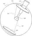
如图1所示,光束控制装置包括光束指向部件和电磁场控制部件。为了清楚地表示各部分,图1并未严格按照比例绘制。其中电磁场控制部件由透明球壳101、导电线圈104、导电线圈105和导电线圈106组成,导电线圈104、导电线圈105和导电线圈106固定于透明球壳101外侧。透明球壳101的内侧为电磁场控制部件的球形空腔。光束指向部件由透明球壳102、永磁体圆盘107和反光表面108组成,永磁体圆盘107和反光表面108固定于透明球壳102内。As shown in FIG. 1, the light beam control device includes a light beam directing part and an electromagnetic field control part. In order to clearly represent the parts, Figure 1 is not drawn strictly to scale. The electromagnetic field control component consists of a transparent
透明球壳102位于透明球壳101之内。电磁场控制部件的透明球壳101外直径为30毫米,内直径为27毫米,光束指向部件的透明球壳102外直径为26毫米,即电磁场控制部件的透明球壳101与光束指向部件的透明球壳102之间存在均匀间隙103。均匀间隙103的厚度为0.5毫米,其中填充的润滑剂为水。透明球壳101和透明球壳102材质为透明石英玻璃。The transparent
导电线圈104、导电线圈105和导电线圈106所在的平面都经过透明球壳101的球心,且这三组导电线圈彼此互相垂直,并缠绕于透明球壳101外部,并由固定卡槽或者固化胶全面固定于透明球壳101。导电线圈104、导电线圈105和导电线圈106分别为单根的漆包无氧铜线,图1为了清晰地解释实施例,夸大了导电线圈104、导电线圈105和导电线圈106的线粗,减少了环绕圈数,实际上导电线圈104、导电线圈105和导电线圈106都是由较细的单根漆包线密集缠绕而成,三根漆包线的规格相同,每根漆包线的导电铜芯直径为0.05毫米,包括绝缘漆层在内的漆包线的线径为0.07毫米,缠绕数为300圈,每根漆包线长度为28.5米~29米,电阻约为250欧姆。每根漆包线缠绕完成后的线圈直径为1.2毫米左右,即导电线圈104、导电线圈105和导电线圈106宏观的线圈直径约为1.2毫米。The planes where the
光束指向部件的永磁体圆盘107外形为圆片,直径为24毫米,厚度为4毫米,位于透明球壳102的中心,并固定于透明球壳102。在本实施例中,永磁体圆盘107为本发明的电磁矩部件,永磁体圆盘107的材质为N38钕铁硼稀土永磁体,充磁方向垂直于永磁体圆盘107的盘片,即N-S极方向垂直于永磁体圆盘107的平面。反光表面108为极薄的平面镜面,位于永磁体圆盘107一端的平面,并覆盖永磁体圆盘107一端的整个平面,并固定于透明球壳102。反光表面108将入射光束109反射,得到出射光束110。透明球壳102的厚度不小于1毫米,实际厚度根据光束指向部件的平均密度要求确定,即根据透明球壳102的材质,计算使得光束指向部件平均密度与均匀间隙103中的润滑液密度相等,因本实施例的润滑液为水,所以透明球壳102的厚度应使得光束指向部件的平均密度=1克/立方厘米。透明球壳102的厚度足够均匀,使得整个光束指向部件的质心位于球形中心。The
控制器如图2所示。导电线圈104的端子111和端子112连接于控制器的X端口,导电线圈105的端子113和端子114连接于控制器的Y端口,导电线圈106的端子115和端子116连接于控制器的Z端口。控制器所输出的信号为电流信号。控制器控制端子111和端子112之间的电流,即控制导电线圈104中的电流,控制器控制端子113和端子114之间的电流,即控制导电线圈105中的电流,控制器控制端子115和端子116之间的电流,即控制导电线圈106中的电流。控制器的三个端口X、Y、Z的电流控制范围都是-12毫安~+12毫安,对应的电压范围大约是-3伏~+3伏。The controller is shown in Figure 2. The
从外形上看,本实施例的导电线圈104、导电线圈105和导电线圈106都是圆环形导体,电流为圆环形电流。由电动力学计算可知,圆环形电流中心轴线上的磁场方向沿该轴线,满足右手定则,且磁感应强度B为In terms of appearance, the

上式中,r为圆环的半径(15毫米),I为圆环形导体截面流过的总电流(12毫安×300=3.6安培),x为距离圆环形导体中心的距离(0),μ为磁导率(本实施例中,除了永磁体圆盘107以外,其他部件的材质的磁导率与真空磁导率接近,因此计算中可以使用真空磁导率μ=4π×10-7牛顿·安培-2)。可以计算出导电线圈104、导电线圈105、导电线圈106中任何一者在光束指向部件的中心产生的磁感应强度可以达到In the above formula, r is the radius of the circular ring (15 mm), I is the total current flowing through the cross-section of the circular conductor (12 mA × 300=3.6 amperes), and x is the distance from the center of the circular conductor (0 ), μ is the magnetic permeability (in this embodiment, except for the

而地球表面地磁场的磁感应强度大约是0.5×10⁻⁴T,即在圆环形电流磁感应强度较弱的中心位置,本实施例也可以输出比地球磁场强的多的磁场。而在圆环形电流的边缘部分可以达到的磁感应强度还要大很多。控制器通过控制导电线圈104、导电线圈105和导电线圈106的电流,在三维方向上控制电磁场控制部件透明球壳101内部球形空腔的磁感应强度,不同方向的磁场会对光束指向部件的永磁体圆盘107产生不同的扭转力矩,使得永磁体圆盘107的盘片与导电线圈104、导电线圈105和导电线圈106输出的磁场方向垂直,从而唯一的控制了光束指向部件的指向。入射光束109经反光表面108反射后变为出射光束110,因为光束指向部件的指向受到控制,即反光表面108的方向受到控制,如此一来,出射光束110的方向就由控制器控制。The magnetic induction intensity of the earth's surface geomagnetic field is about 0.5×10⁻⁴ T, that is, at the central position where the magnetic induction intensity of the annular current is weak, this embodiment can also output a magnetic field much stronger than the earth's magnetic field. The magnetic induction intensity that can be achieved at the edge of the circular current is much larger. The controller controls the magnetic induction intensity of the inner spherical cavity of the transparent
对于本实施例,虽然计算出来的导电线圈104、导电线圈105和导电线圈106的磁感应强度上限与地磁场磁感应强度在相近数量级上,但是由于圆环形电流在中心的磁感应强度较小,而在靠近边缘处磁感应强度会大很多,所以实际上即使不使用磁场敏感器的测量数值去补偿,也可以获得较高的光束指向部件的指向精度。实验也验证了这一点,在线圈电流只有7毫安的时候,导电线圈104、导电线圈105和导电线圈106所输出的磁场,已经可以给光束指向部件施加足够大的扭转力矩,并可获得较高的指向精度。For this embodiment, although the calculated upper limit of the magnetic induction intensity of the
为了获得更高的控制精度,优选的方案是,如图2所示,增加一个磁场敏感器,该磁场敏感器与光束控制装置的电磁场控制部件是相对固定的。磁场敏感器测量三维磁场,并将测量得到的三维磁场数据发送给控制器。控制器在控制导电线圈104、导电线圈105和导电线圈106的电流时,在原本的目标电流上分别加上各自的补偿电流值,这三个补偿电流值应满足:当导电线圈104、导电线圈105和导电线圈106的电流分别为各自的补偿电流值时,永磁体圆盘107所受到的环境磁场力矩(主要是地磁场力矩)与受到的三组导电线圈所施加的磁场力矩之和为零。In order to obtain higher control accuracy, a preferred solution is to add a magnetic field sensor as shown in FIG. 2 , and the magnetic field sensor is relatively fixed to the electromagnetic field control part of the light beam control device. The magnetic field sensor measures the three-dimensional magnetic field, and sends the measured three-dimensional magnetic field data to the controller. When the controller controls the currents of the
如果光束控制装置的电磁场控制部件的空间指向是实时变化的,那么这三个补偿电流值一般也是实时变化的。本实施例中是通过实验确定了当光束控制装置的电磁场控制部件指向各种方向时的三个补偿电流值。当然,使用磁场CAD设计软件也可以更直接的获得所有方向上的三个补偿电流值。If the spatial orientation of the electromagnetic field control part of the light beam control device changes in real time, then the three compensation current values generally also change in real time. In this embodiment, three compensation current values are determined through experiments when the electromagnetic field control part of the light beam control device points in various directions. Of course, the three compensation current values in all directions can also be obtained more directly using magnetic field CAD design software.
需要注意的是磁场敏感器与光束控制装置之间应有足够的距离,避免光束控制装置所产生的磁场影响磁场敏感器的测量精度。It should be noted that there should be enough distance between the magnetic field sensor and the beam control device to avoid the magnetic field generated by the beam control device from affecting the measurement accuracy of the magnetic field sensor.
机械系统不可避免地存在摩擦。本实施例中的摩擦存在于电磁场控制部件的透明球壳101内表面与光束指向部件的透明球壳102的外表面之间。该摩擦有两种,一种是润滑液(本实施例是水)产生的滑动摩擦,该摩擦的大小正比于透明球壳101和透明球壳102的相对转动速度,而且摩擦力的方向与透明球壳101、透明球壳102的相对转动方向相反,这种滑动摩擦是本发明所需要的,因为控制器所输出的仅仅是目标指向(本实施例是目标磁场方向)所对应的导电线圈104、导电线圈105和导电线圈106的电流,这是一种纯粹的位置控制。根据控制理论,对于二阶系统而言,纯粹的位置控制是不稳定的。但是由于均匀间隙103中润滑液滑动摩擦而产生了速度负反馈,使得控制变为速度负反馈+位置负反馈控制,即PD控制,从而控制稳定性得到解决。第二种摩擦是透明球壳101和透明球壳102之间存在的静摩擦,这种摩擦主要由于表面加工的瑕疵、缺陷,以及光束指向部件平均密度偏差、质心位置的偏差等造成。这种静摩擦对于本实施例而言是有害的,可能造成光束指向部件在转动过程中卡顿、不流畅,以及最终的控制指向精度存在偏差。通过使用脉宽调制方式来控制电流,即PWM方式,可以解决静摩擦的问题。Friction is inevitable in mechanical systems. The friction in this embodiment exists between the inner surface of the transparent
脉宽调制技术(即Pulse Width Modulation,首字母缩写为PWM),原理是控制信号在控制上限和控制下限之间切换,通过控制输出位于控制上限和控制下限时长的比例,即占空比,从时间平均的角度获得所需数值的控制输出。如图3所示,目标输出为一匀速上升的斜坡信号,PWM方式通过调节占空比,其时间均值输出就为匀速上升的斜坡信号。使用PWM方式进行控制要求被控对象是二阶系统或者更高阶的系统,本发明的系统从数学角度就是二阶系统,所以可以使用PWM控制。PWM控制的时间片段长度需要根据被控系统的惯性选择,对于本实施例,采用的是10毫秒宽度的时间片段,即控制器对于导电线圈104、导电线圈105和导电线圈106中电流的控制方式为,调节每10毫秒内的最大输出和最小输出的占空比,使得时间均值电流为需要的目标电流值。由于导电线圈104、导电线圈105和导电线圈106的电流值在上限12毫安和下限-12毫安之间切换,所以在三个方向上,光束指向部件受到的扭矩也在最大和反向最大之间不断切换,即使存在静摩擦,由于扭矩的这种不断切换就可以克服静摩擦,并最终将光束指向部件定位到目标方向。Pulse width modulation technology (ie Pulse Width Modulation, acronym for PWM), the principle is that the control signal is switched between the upper control limit and the lower control limit, by controlling the ratio of the output at the upper control limit and the lower control limit, that is, the duty cycle, from Time-averaged angle to obtain the desired value of the control output. As shown in Figure 3, the target output is a ramp signal that rises at a constant speed. By adjusting the duty ratio in PWM mode, the time average output is a ramp signal that rises at a constant speed. Using PWM mode to control requires the controlled object to be a second-order system or a higher-order system. The system of the present invention is a second-order system from a mathematical point of view, so PWM control can be used. The length of the time segment of PWM control needs to be selected according to the inertia of the controlled system. For this embodiment, a time segment with a width of 10 milliseconds is used, that is, the controller controls the current in the
PWM输出的时间片段长度越小,则控制对象的抖动幅度就越小,但是在本实施例中,时间片段的减小受到线圈自感和控制器驱动能力的限制。实验表明,本实施例采用10ms的长时间片段,光束指向部件的抖动依然是可以接受的。PWM方式的缺点是能耗较高,为了降低能耗,可以间歇采用PWM方式,或者在普通的控制电流的基础上增加部分幅值的PWM控制,而不是采用电流上限与电流下限之间切换的全幅值切换方式。The shorter the time segment length of the PWM output is, the smaller the jitter amplitude of the control object is, but in this embodiment, the reduction of the time segment is limited by the coil self-inductance and the driving capability of the controller. Experiments show that the jitter of the beam pointing component is still acceptable when a long time segment of 10ms is used in this embodiment. The disadvantage of the PWM method is that the energy consumption is high. In order to reduce the energy consumption, the PWM method can be used intermittently, or the PWM control of part of the amplitude can be added on the basis of the ordinary control current, instead of switching between the current upper limit and the current lower limit. Full amplitude switching mode.
对于本实施例,导电线圈104、导电线圈105和导电线圈106同时最大输出,功耗是For this embodiment, the

即工作时电磁场控制部件本身的最大功耗大约为108毫瓦,作为3厘米尺寸的装置而言,功耗是比较小的,即使由现在的普通手机供电也可以持续不间断工作50小时以上,而如果优化PWM控制方式,采用间断式PWM或者部分式PWM则功耗还可降低大部分。That is, the maximum power consumption of the electromagnetic field control component itself is about 108 mW during operation. As a device with a size of 3 cm, the power consumption is relatively small. Even if it is powered by a current ordinary mobile phone, it can continue to work continuously for more than 50 hours. And if the PWM control method is optimized, the power consumption can be reduced by most of the discontinuous PWM or partial PWM.
对于本实施例,虽然导电线圈104、导电线圈105和导电线圈106并不透明,但是由于其线径较细,因此对于光束的遮挡可以忽略。如果采用分散式的方式将导电线圈以一定间隔分布缠绕于透明球壳101外,可以使得对于光束的遮挡均匀一些。In this embodiment, although the
实施例二:Embodiment 2:
如图4所示,光束控制装置包括光束指向部件和电磁场控制部件。为了清楚地表示各部分,图4并未严格按照比例绘制。其中电磁场控制部件由透明球壳201、导电线圈204、导电线圈205和导电线圈206组成,导电线圈204、导电线圈205和导电线圈206固定于透明球壳201外侧。透明球壳201的内侧为电磁场控制部件的球形空腔,光束指向部件位于其中。光束指向部件由透明球壳202、永磁体圆盘207、磁场感应线圈208和发光元件209组成,永磁体圆盘207固定于透明球壳202内,磁场感应线圈208和发光元件209固定于永磁体圆盘207。As shown in FIG. 4, the light beam control device includes a light beam pointing part and an electromagnetic field control part. For clarity of representation, Figure 4 is not drawn strictly to scale. The electromagnetic field control component consists of a transparent
透明球壳202位于透明球壳201之内。电磁场控制部件的透明球壳201外直径为6.0毫米,内直径为5.4毫米,光束指向部件的透明球壳202外直径为5.2毫米,即电磁场控制部件的透明球壳201与光束指向部件的透明球壳202之间存在均匀间隙203。均匀间隙203的厚度为0.1毫米,其中填充的润滑剂为四氯化碳。透明球壳201和透明球壳202材质为透明聚四氟乙烯。The transparent
导电线圈204、导电线圈205和导电线圈206所在平面都经过透明球壳201的球心,且这三组导电线圈彼此互相垂直,并缠绕于透明球壳201外部,并由固定卡槽或者固化胶全面固定于透明球壳201。导电线圈204、导电线圈205和导电线圈206分别为单根漆包无氧铜线,图4为了清晰地解释本实施例,夸大了导电线圈204、导电线圈205和导电线圈206的线粗,减少了环绕圈数。实际上导电线圈204、导电线圈205和导电线圈206都是由较细的单根漆包线密集缠绕而成,三根漆包线的规格相同,每根漆包线的导电铜芯直径为0.01毫米,包括绝缘漆层在内的漆包线的线径为0.012毫米,缠绕数为300圈,每根漆包线长度为5.7米~5.8米,电阻约为1250欧姆。每根漆包线缠绕完成后的线圈直径为0.24毫米,即导电线圈204、导电线圈205和导电线圈206宏观的线圈直径都是0.24毫米。The planes where the
光束指向部件的永磁体圆盘207外形为圆片,直径为4.8毫米,厚度为0.8毫米,位于透明球壳202的中心,并固定于透明球壳202。在本实施例中,永磁体圆盘207为本发明的电磁矩部件。永磁体圆盘207的材质为N38钕铁硼稀土永磁体,充磁方向垂直于永磁体圆盘207的盘片,即永磁体的N-S方向垂直于永磁体圆盘207的两侧平面。磁场感应线圈208固定于永磁体圆盘207一端的平面,且两端与发光元件209的两个输入端电连接。磁场感应线圈208感应磁场变化,将感应得到的感应电流输出给发光元件209。发光元件209具有激光二极管,激光发射方向与永磁体盘面207的两侧平面垂直。发光元件209自带有解调芯片,该解调芯片从磁场感应线圈208所输出的感应电流中获得能量,给发光元件209的激光二极管提供工作能源;同时该解调芯片从磁场感应线圈208所输出的感应电流中解调出信息,并根据该信息控制发光元件209的发光强度,发射出去含有该信息的出射光束210。透明球壳202的厚度不小于0.2毫米,实际厚度根据光束指向部件的平均密度要求确定,即根据透明球壳202的材质,计算使得光束指向部件平均密度与均匀间隙203中的润滑液密度相等。透明球壳202的厚度足够均匀,使得整个光束指向部件的质心位于球形中心。The
控制器如图2所示,导电线圈204的端子211和端子212连接于控制器的X端口,导电线圈205的端子213和端子214连接于控制器的Y端口,导电线圈206的端子215和端子216连接于控制器的Z端口。控制器所输出的信号为电流信号。控制器控制端子211和端子212之间的电流,即控制导电线圈204中的电流,控制器控制端子213和端子214之间的电流,即控制导电线圈205中的电流,控制器控制端子215和端子216之间的电流,即控制导电线圈206中的电流。控制器的三个端口X、Y、Z的电流控制范围都是-2.4毫安~+2.4毫安,对应的电压范围大约是-3伏~+3伏。The controller is shown in FIG. 2 , the
本实施例的导电线圈204、导电线圈205和导电线圈206都是圆环形导线。由电动力学计算可知,导电线圈104、导电线圈105、导电线圈106中任何一者在光束指向部件的中心产生的磁感应强度可以达到The

所以本实施例与实施例一的磁感应强度相同。采用与实施例一同样的方式,控制器控制电磁场控制部件的导电线圈204、导电线圈205和导电线圈206的电流,在三维方向上控制电磁场控制部件透明球壳201内部球形空腔的磁感应强度,对光束指向部件的永磁体圆盘207施加扭转力矩,使得永磁体圆盘207的盘片与导电线圈204、导电线圈205和导电线圈206输出的磁场方向垂直,从而唯一的控制了光束指向部件的指向。类似于实施例一,本实施例同样可以借鉴磁场敏感器的磁场测量数值,对导电线圈204、导电线圈205和导电线圈206的电流进行补偿或修正,克服环境磁场(主要是地球磁场)的影响。类似于实施例一,本实施例同样可以采用间断式的PWM控制方式,或者在普通控制输出上叠加一个部分大小的PWM控制,以克服静态摩擦。Therefore, the magnetic induction intensity of this embodiment is the same as that of the first embodiment. In the same way as in the first embodiment, the controller controls the current of the
对于本实施例,导电线圈204、导电线圈205和导电线圈206同时最大输出,功耗是For this embodiment, the

即工作时电磁场控制部件本身的极值功耗大约为21.6毫瓦,功耗降低为30毫米尺寸的实施例一的1/5,即在确保光束指向部件获得同样的磁感应强度的前提下,如果成比例地缩小基于磁矩的本发明的尺寸,那么电磁场控制部件消耗的功耗会成比例下降。That is, the extreme power consumption of the electromagnetic field control part itself is about 21.6 mW during operation, and the power consumption is reduced to 1/5 of the first embodiment with a size of 30 mm. By scaling down the size of the magnetic moment-based invention, the power consumed by the electromagnetic field control components will be proportionally reduced.
润滑剂四氯化碳与水的粘度差别不大,这里假设他们的粘度是相同的。当所有的尺寸成比例地缩小后(用符号k表示本实施例与实施例一的尺寸比例系数,这里k=1/5),电磁场控制部件的透明球壳201与光束指向部件的透明球壳202之间的滑动摩擦系数(下式中简称滑动摩擦系数)与永磁体圆盘207受到的磁力矩(下式中简称磁力矩)之比却成比例地增大,即有关系式:The viscosity of the lubricant carbon tetrachloride is not much different from that of water, and it is assumed that their viscosities are the same. When all the dimensions are proportionally reduced (the symbol k is used to represent the size ratio coefficient between this embodiment and the first embodiment, where k=1/5), the transparent
滑动摩擦系数/磁力矩=1/k=5Sliding friction coefficient/magnetic torque=1/k=5
其原因是,关于转动角速度的滑动摩擦系数与接触面积成正比,与间隙厚度成反比,与透明球壳201和透明球壳202的半径成正比,所以当整个光束控制装置的尺寸按照比例k缩小后,滑动摩擦系数变为实施例一的k2,而磁场的磁感应强度不变,永磁体体积变为实施例一的k3,所以磁矩、磁力矩都变为实施例一的k3,从而有上式。这带来的影响是等价地增大了PD控制中的速度负反馈项。对于本发明而言,这种增大是不利的。但是可以通过提高永磁体磁密度、厚度,或者提高导电线圈204、导电线圈205和导电线圈206中的电流,或者适当增加均匀间隙203等方式来改善。The reason is that the sliding friction coefficient with respect to the rotational angular velocity is proportional to the contact area, inversely proportional to the thickness of the gap, and proportional to the radii of the transparent
本实施例中,磁场感应线圈208所感应到的磁场信号由控制器控制导电线圈204、导电线圈205和导电线圈206而产生,即控制器输出的三个线圈中的电流同时完成三个功能:1、控制电磁场控制部件的球形空腔内的磁感应强度;2、通过输出交流磁场,由光束指向部件的磁场感应线圈208为发光元件209供电;3、通过输出交流磁场,经过光束指向部件的磁场感应线圈208为发光元件209传输信号。这三个功能得以同时实现是基于分频技术,即三个功能基于的工作频率不同,分别为较低频、中频、高频。In this embodiment, the magnetic field signal sensed by the magnetic
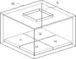
本实施例还具有如图15所示的光束方向检测部件,该检测部件属于现有技术,R2为上方开方孔的薄壁箱体,不透明,图15的透视效果是为了说明内部结构。R2底部有4块矩形光强度传感器S1、S2、S3、S4,当光束从开孔R1射入箱体内部后,根据入射角度的不同,在S1、S2、S3、S4上照射光斑的面积也会不同,从而4个光强度传感器的输出量也不同,根据这四块光强度传感器输出信号的比例,解析出入射光线的方向。控制器控制电磁场控制部件的球形空腔的磁场,从而控制光束指向部件的出射光束沿着入射光束的反方向。This embodiment also has a beam direction detection component as shown in FIG. 15 , which belongs to the prior art. R2 is a thin-walled box with a square hole above, which is opaque. The perspective effect of FIG. 15 is to illustrate the internal structure. There are 4 rectangular light intensity sensors S1, S2, S3, S4 at the bottom of R2. When the light beam is injected into the box from the opening R1, the area of the light spot irradiated on S1, S2, S3 and S4 is also different depending on the angle of incidence. Therefore, the outputs of the four light intensity sensors are also different. According to the ratio of the output signals of the four light intensity sensors, the direction of the incident light is analyzed. The controller controls the magnetic field of the spherical cavity of the electromagnetic field control member, thereby controlling the outgoing beam of the beam pointing member to be in the opposite direction of the incident beam.
实施例三:Embodiment three:
如图6所示,光束控制装置包括光束指向部件和电磁场控制部件。为了清楚地表示各部分,图6并未严格按照比例绘制。As shown in FIG. 6 , the light beam control device includes a light beam pointing part and an electromagnetic field control part. For clarity of representation, Figure 6 is not drawn strictly to scale.
电磁场控制部件由透明球壳301、导电线圈304、导电线圈305和导电线圈306组成。透明球壳301的内侧为电磁场控制部件的球形空腔,光束指向部件位于其中。电磁场控制部件的透明球壳301的材质为石英玻璃,外直径为3.0毫米,内直径为2.7毫米。导电线圈304、导电线圈305和导电线圈306都固定于透明球壳301的外侧,并且这三组导电线圈所在的平面都经过透明球壳301的球心。为了清晰地解释本实施例,图6夸张地表现了这三组导电线圈。实际上,导电线圈304、导电线圈305和导电线圈306都是由单根银漆包线密集缠绕在各自的环形导线槽中,三个导线槽都固定于透明球壳301外侧。漆包线的导电银芯直径为0.01毫米,包含绝缘漆层在内的漆包线的线径为0.012毫米。每组的缠绕数都为150圈,每根漆包线长度为1.45米~1.5米,电阻约为320欧姆。图6在317位置处的剖面如图7所示,如其中所示,导线槽横截面为梯形,窄边固定于透明球壳301外表面,窄边宽度为0.1毫米,梯形高度为0.19毫米,且梯形的两腰延长线都经过透明球壳301的球心,导线槽内的导线只是示意,实际的导线要密很多。在两个导线槽交叉的位置处,一个导线槽跨过另一个导线槽。The electromagnetic field control part is composed of a transparent
光束指向部件由透明球壳302、永磁体圆盘307、光敏元件308和发光元件309组成。透明球壳302外直径为2.6毫米,材质为透明石英玻璃。在本实施例中,永磁体圆盘307为本发明的电磁矩部件,材质为N52钕铁硼稀土永磁体,充磁方向为厚度方向,即永磁体的N-S方向垂直于永磁体圆盘307的两侧平面。永磁体圆盘307外形为圆片,直径为2.4毫米,厚度为0.4毫米,位于透明球壳302的中心,并固定于透明球壳302的内部中心位置。如图8和图9所示,光敏元件308固定于永磁体圆盘307的两侧平面。发光元件309固定于永磁体圆盘307一侧平面的中心。光敏元件308的正负极分别与发光元件309的正负极电连接。发光元件309为VCSEL垂直腔面发射激光器,激光发射方向与永磁体圆盘307垂直。光敏元件308接收外界传来的光信号,并转化为电信号,直接控制发光元件309所发出的出射光束310的强度。透明球壳302的厚度使得光束指向部件的平均密度与均匀间隙303中的润滑液密度相等。The light beam pointing part is composed of a transparent
光束指向部件的透明球壳302在电磁场控制部件的透明球壳301的球形空腔之内,透明球壳301与透明球壳302之间存在均匀间隙303。均匀间隙303的厚度为0.05毫米,其中填充的润滑剂为纯净汽油(馏程150摄氏度左右),并填充有少量直径10微米左右的透明聚四氟乙烯球形颗粒。The transparent
控制器如图2所示,导电线圈304的端子311和端子312连接于控制器的X端口,导电线圈305的端子313和端子314连接于控制器的Y端口,导电线圈306的端子315和端子316连接于控制器的Z端口。控制器所输出的信号为电流信号。控制器控制端子311和端子312之间的电流,即控制导电线圈304中的电流,控制器控制端子313和端子314之间的电流,即控制导电线圈305中的电流,控制器控制端子315和端子316之间的电流,即控制导电线圈306中的电流。控制器的三个端口X、Y、Z的电流控制范围都是-6毫安~+6毫安,对应的电压范围大约是-1.92伏~+1.92伏。The controller is shown in FIG. 2 , the
本实施例的导电线圈304、导电线圈305和导电线圈306中任何一者在光束指向部件的中心产生的磁感应强度可以达到The magnetic induction intensity generated by any one of the

该数值大于地球表面磁场0.5×10⁻⁴T。导电线圈304、导电线圈305和导电线圈306同时峰值输出的总功耗是This value is greater than 0.5×10⁻⁴ T of the Earth's surface magnetic field. The total power dissipation for the simultaneous peak output of

即工作时电磁场控制部件本身的极值功耗大约为34.56毫瓦。That is, the extreme power consumption of the electromagnetic field control component itself is about 34.56 mW during operation.
汽油的粘度大约为水的40%,因此有助于减小透明球壳301与透明球壳302之间的滑动摩擦系数,且加入少量的聚四氟乙烯球状微粒也进一步减小了滑动摩擦系数。The viscosity of gasoline is about 40% of that of water, so it helps to reduce the sliding friction coefficient between the transparent
导电线圈304、导电线圈305和导电线圈306互相垂直,分别负责输出一个方向上的磁场。从数学上,出射光束310的目标指向可以由三维矢量表示,控制器根据该三维矢量,控制导电线圈304、导电线圈305和导电线圈306中的电流大小和方向,使得三个方向上的磁感应强度所组成的三维矢量与出射光束310的目标指向的三维矢量方向相同。而且为了获得尽可能高的指向精度,三组导电线圈中至少有一个的电流的绝对值达到极值电流6毫安。The
如图2所示的磁场敏感器与电磁场控制部件是相对固定的,磁场敏感器将测量得到的三维磁场数据发送给控制器。控制器在控制导电线圈304、导电线圈305和导电线圈306的电流时,在原本的目标电流上分别加上各自的补偿电流值,这三个补偿电流值满足:当导电线圈304、导电线圈305和导电线圈306的电流分别为各自的补偿电流值时,永磁体圆盘307所受到的环境磁场力矩(主要是地磁场力矩)与受到的三组导电线圈所施加的磁场力矩之和为零。As shown in Figure 2, the magnetic field sensor and the electromagnetic field control component are relatively fixed, and the magnetic field sensor sends the measured three-dimensional magnetic field data to the controller. When controlling the currents of the
每间隔20毫秒,控制器控制导电线圈304、导电线圈305和导电线圈306的方式由普通控制,变为1毫秒的PWM控制。Every 20 milliseconds, the way the controller controls the
实施例四:Embodiment 4:
光束控制装置包括光束指向部件和电磁场控制部件。The light beam control device includes a light beam pointing part and an electromagnetic field control part.
电磁场控制部件如图10和图11所示,其中图10是前视图,图11是后视图。电磁场控制部件为透明球壳401,外直径10毫米,厚度为1毫米,材料为透明石英玻璃。透明球壳401内部为本发明的球形空腔,光束指向部件位于其中。透明球壳401镶嵌有多片电极,电极位于透明球壳的球形空腔外侧,且距离透明球壳401的球形空腔表面的距离为0.05毫米。电极厚度为0.2毫米。电极材料为ITO,即氧化铟锡,是透明的。本发明的电极形状采用足球的表面分割设计,共有32个彼此分离的电极。电极405、电极406、电极415和电极416是电极的部分代表。关于球形空腔的球心为中心对称的两个电极组成一对,比如电极405和电极415是一对,电极406和电极416是一对,一对电极由两根导线引出(导线在图10和图11中没有示出),并连接至控制器的一个端口。如图12所示的控制器,每一个长线和下方相邻的短线为一个端口,控制器共有16个端口,分别与电磁场控制部件的16对电极相连。The electromagnetic field control component is shown in Figures 10 and 11, wherein Figure 10 is a front view and Figure 11 is a rear view. The electromagnetic field control component is a transparent
如图13所示,光束指向部件由透明球壳402、电极对404和发光元件409组成。透明球壳402外直径为9.5毫米,材料为石英玻璃。发光元件409固定于透明球壳402的中心。电极对404为本发明的电磁矩部件,包含两个分离的电极,两个电极关于透明球壳402的球心中心对称,且两电极的连线沿着发光元件409的出射光束方向。电极对404的每一个电极的形状为环形、球面片状,环形外径为4毫米,片厚度为0.1毫米,中心通孔直径为2.5毫米。电极材料为无氧铜。电极对404镶嵌于透明球壳402,且与透明球壳402外表面等间距,且距离透明球壳402的外表面的距离为0.05毫米。电极对404中间的通孔用于通过发光元件409发出的出射光束410。电极对404的两个电极与发光元件409的正负极之间通过两根导线408连接。As shown in FIG. 13 , the light beam directing member is composed of a transparent
光束指向部件的透明球壳402位于电磁场控制部件的透明球壳401之中,且透明球壳401和透明球壳402之间存在0.25毫米厚的间隙,其中填充纯净汽油(馏程150摄氏度左右)。The transparent
如图12所示的控制器,通过控制16个端口的电压,控制电磁场控制部件的32个电极上的电荷,从而控制电磁场控制部件球形空腔内的电场,该电场在光束指向部件的电极对404上产生感应电荷,此感应电荷使得电极对404具有电偶极矩,从而受到球形空腔内的电场的转动力矩,使得光束指向部件的光束指向沿电磁场控制部件的球形空腔内的电场方向。利用感应电荷产生驱动力,即本实施例的驱动原理是基于电容可变原理的静电驱动。根据指向精度和指向速度的不同要求,控制器输出的端口电压量程可以为10V级别、100V级别、1000V级别等。The controller as shown in Figure 12 controls the electric charge on the 32 electrodes of the electromagnetic field control part by controlling the voltage of the 16 ports, thereby controlling the electric field in the spherical cavity of the electromagnetic field control part, which is in the electrode pair of the beam pointing part. An induced charge is generated on 404, and this induced charge makes the
控制器在输出端口电压以控制球形空腔内电场时,在基本的控制电压上加上高频的交变电压,交变电压的频率受到控制器的调制,带有信息。交变电压在电极对404上产生感应的交变电压,施加到发光元件409,发光元件409具有调制单元,根据接收的电信号控制出射光束410的偏振态。When the controller outputs the port voltage to control the electric field in the spherical cavity, a high-frequency alternating voltage is added to the basic control voltage, and the frequency of the alternating voltage is modulated by the controller with information. The alternating voltage generates an induced alternating voltage on the
实施例五:Embodiment 5:
与实施例四相同,除了以下两个部分:1、电磁矩部件由电极对404替换为如图14所示的电极对504,没有中间的通孔,材料为透明的石墨烯薄膜。电极对504的两个电极分别带有预充的正、负电荷,且两个电极之间的电压为1000V级别。与实施例四不同的是,本实施例的电磁矩部件的电偶极矩由预充电荷产生,不是由于球形空腔内的电场而感应产生。2、导线408替换为光敏元件508,该光敏元件固定于光束指向部件,并与发光元件409电连接。光敏元件508接收外界光信号并转化为电信号,传输给发光元件409。发光元件409具有调制单元,根据接收的电信号控制出射光束410的波长和相位。The same as the fourth embodiment, except for the following two parts: 1. The electromagnetic moment component is replaced by the
本发明中所使用的术语都应依据规范和字面含义理解。这里对于部分术语进行更详细的说明。The terms used in the present invention should be understood according to the norm and the literal meaning. Some terms are explained in more detail here.
“指向”的含义为物体的空间姿态,即物体在空间中的方向、朝向、或倾斜和方位角度等。The meaning of "pointing" is the spatial attitude of the object, that is, the direction, orientation, or inclination and azimuth angle of the object in space.
“磁矩方向”的含义参照物理学标准定义;对于磁体而言,近似的理解是南北极连线方向。The meaning of "magnetic moment direction" is defined with reference to physical standards; for magnets, the approximate understanding is the direction of the line connecting the north and south poles.
“电偶极矩方向”的含义参照物理学标准定义;对于电极对而言,近似的理解是正负极连线方向。The meaning of "direction of electric dipole moment" is defined with reference to physical standards; for electrode pairs, the approximate understanding is the direction of the connection between the positive and negative electrodes.
“多个”、“多对”等词语中的“多”的含义是数量不少于2。即“多个”指两个或者两个以上,“多对”指两对或者两对以上。The meaning of "multiple" in words such as "plurality" and "multiple pairs" means that the number is not less than 2. That is, "plurality" refers to two or more, and "multiple pairs" refers to two or more pairs.
“集中环绕”指导线以聚集在一束、一环或一起的方式环绕。Concentrate Wrap guides wrap around in a bunch, ring, or together.
“分散环绕”指导线以螺旋间隔的方式、或者平行间隔的方式、或者其他间隔的方式进行环绕。A "scattered wrap" guides the lines to wrap around in a helical spaced manner, or a parallel spaced manner, or other spaced manner.
“电极对”应理解为,两个电极。"Electrode pair" should be understood to mean two electrodes.
“电连接”应理解为,通过导体连接。"Electrically connected" is to be understood as being connected by means of conductors.
“透明”应当理解为,介质可以使该波长的电磁波至少部分地透射。"Transparent" is understood to mean that the medium is at least partially transparent to electromagnetic waves of that wavelength.
“控制器”可以是微电子控制器件、控制电路、电脑、PLC、单片机、FPGA、工控机、移动设备等,以及其他具有控制功能的元件或装置。The "controller" can be a microelectronic control device, a control circuit, a computer, a PLC, a single-chip microcomputer, an FPGA, an industrial computer, a mobile device, etc., as well as other components or devices with control functions.
“函数”的含义参考数学关于函数的定义;可以理解为,一个量是由另外的一个或多个量按照一定的关系决定。The meaning of "function" refers to the definition of functions in mathematics; it can be understood that a quantity is determined by one or more other quantities according to a certain relationship.
“球壳”应当理解为,由两个同球心的球面所夹的部分,以及以两个同球心的球面所夹的部分为基础,经雕刻、增补、修改等得到的物体。"Spherical shell" should be understood as the part sandwiched by two concentric spherical surfaces, and the object obtained by carving, supplementing, modifying, etc. on the basis of the part sandwiched by two concentric spherical surfaces.
球壳的“厚度”指球壳壁的厚度。The "thickness" of a spherical shell refers to the thickness of the spherical shell wall.
单位“T”为磁感应强度的单位特斯拉。The unit "T" is the unit Tesla of magnetic induction.
“占空比”的含义参考信号处理等相关学科的定义,简单说,对于只取两个值的信号而言,“占空比”指在一个时间片段里信号取大值的时间所占的比例;对于周期信号而言,“占空比”的含义是在一个周期里信号取大值的时间长度所占周期时长的比例。The meaning of "duty cycle" refers to the definition of related disciplines such as signal processing. In short, for a signal that only takes two values, "duty cycle" refers to the time occupied by the signal taking a large value in a time segment. Proportion; for periodic signals, the meaning of "duty cycle" is the ratio of the time length of the signal taking a large value to the cycle length in a cycle.
“光束”应道理解为传播方向为平行或者传播方向锥角小于360度的电磁波。其中,光,不仅仅可以为可见光,还可以为红外光、紫外光、X射线、微波等各种可能波长的电磁波。"Light beam" should be understood as an electromagnetic wave whose propagation direction is parallel or whose propagation direction cone angle is less than 360 degrees. The light can be not only visible light, but also electromagnetic waves with various possible wavelengths such as infrared light, ultraviolet light, X-ray, and microwave.
“目标电流”、“目标磁场”等词中的“目标”的含义是控制的指令值,即控制所要达到的状态、数值等。The meaning of "target" in words such as "target current" and "target magnetic field" is the command value of the control, that is, the state, value, etc. to be achieved by the control.
基于上述原理,可以有许多修改和变型。选择和描述具体的实施方式是为了最好地的解释公开的原理及其实际应用,从而使得本领域的其他技术人员能够最好地利用各种修改的实施方式来满足预期的特定用途。Based on the above principles, many modifications and variations are possible. The specific embodiment was chosen and described in order to best explain the disclosed principles and their practical application, to thereby enable others skilled in the art to best utilize various modified embodiments to suit the particular use contemplated.
本文的具体实施方式都不是限定性的描述,可以依据实际需要组合本发明的各种技术特征。具体实施方式中没有详细列举的组合方式、结构设计、参数选择等,本领域内一般工程技术人员可以根据具体情况灵活选择。但是任何包括了本发明技术特征的技术方案、技术设计等,都落入本发明的保护范围。The specific embodiments herein are not restrictive descriptions, and various technical features of the present invention can be combined according to actual needs. The combination mode, structural design, parameter selection, etc., which are not listed in detail in the specific implementation manner, can be flexibly selected by ordinary engineers and technicians in the art according to specific conditions. However, any technical solutions, technical designs, etc. that include the technical features of the present invention fall into the protection scope of the present invention.
Claims (13)
Translated fromChinesePriority Applications (3)
| Application Number | Priority Date | Filing Date | Title |
|---|---|---|---|
| CN201710553949.8ACN109212787B (en) | 2017-07-09 | 2017-07-09 | Light beam control device |
| PCT/CN2018/091886WO2019011111A1 (en) | 2017-07-09 | 2018-06-19 | Beam control apparatus |
| US16/700,120US11215816B2 (en) | 2017-07-09 | 2019-12-02 | Beam control apparatus |
Applications Claiming Priority (1)
| Application Number | Priority Date | Filing Date | Title |
|---|---|---|---|
| CN201710553949.8ACN109212787B (en) | 2017-07-09 | 2017-07-09 | Light beam control device |
Publications (2)
| Publication Number | Publication Date |
|---|---|
| CN109212787A CN109212787A (en) | 2019-01-15 |
| CN109212787Btrue CN109212787B (en) | 2020-09-29 |
Family
ID=64991637
Family Applications (1)
| Application Number | Title | Priority Date | Filing Date |
|---|---|---|---|
| CN201710553949.8AExpired - Fee RelatedCN109212787B (en) | 2017-07-09 | 2017-07-09 | Light beam control device |
Country Status (3)
| Country | Link |
|---|---|
| US (1) | US11215816B2 (en) |
| CN (1) | CN109212787B (en) |
| WO (1) | WO2019011111A1 (en) |
Families Citing this family (5)
| Publication number | Priority date | Publication date | Assignee | Title |
|---|---|---|---|---|
| RU2729336C1 (en)* | 2019-08-28 | 2020-08-06 | Федеральное государственное казенное военное образовательное учреждение высшего образования "Военный учебно-научный центр Военно-воздушных сил "Военно-воздушная академия имени профессора Н.Е. Жуковского и Ю.А. Гагарина" (г. Воронеж) Министерства обороны Российской Федерации | Control method of unmanned aerial vehicle of small class |
| CN111290117A (en)* | 2019-12-24 | 2020-06-16 | 哈尔滨新光光电科技股份有限公司 | Light beam pointing control method and system |
| CN115299786B (en)* | 2021-05-07 | 2025-04-08 | 深圳市和生创新技术有限公司 | Control method and stepless speed control method for air fryer, and system and equipment thereof |
| US20230118396A1 (en)* | 2021-10-18 | 2023-04-20 | Canyon Consulting, LLC | Steerable antenna system and method |
| CN115618650B (en)* | 2022-11-15 | 2023-04-28 | 中国电子科技集团公司第十研究所 | Method for correcting virtual sphere center position coordinates of spherical phased array antenna |
Citations (5)
| Publication number | Priority date | Publication date | Assignee | Title |
|---|---|---|---|---|
| CN101108279A (en)* | 2006-07-18 | 2008-01-23 | 比内克思创新产品开发有限公司 | object with rotation effect |
| CN101470237A (en)* | 2007-12-25 | 2009-07-01 | 鸿富锦精密工业(深圳)有限公司 | Rotatable camera module group |
| CN201438957U (en)* | 2009-05-21 | 2010-04-21 | 巨豪实业股份有限公司 | Suspension Steering Structure of Spherical Interior Mirror |
| CN102175235A (en)* | 2011-01-21 | 2011-09-07 | 南京航空航天大学 | Spherical piezoelectric stator type gyroscope |
| CN105783897A (en)* | 2014-12-18 | 2016-07-20 | 重庆富鑫玻璃有限公司 | Electrostatic bearing gyroscope |
Family Cites Families (3)
| Publication number | Priority date | Publication date | Assignee | Title |
|---|---|---|---|---|
| US7136547B2 (en)* | 2001-03-30 | 2006-11-14 | Gsi Group Corporation | Method and apparatus for beam deflection |
| WO2013009550A2 (en) | 2011-07-13 | 2013-01-17 | Bae Systems Integration And Electronic Systems Integration Inc. | Beam shaping and control apparatus |
| US9442185B2 (en)* | 2014-05-01 | 2016-09-13 | Raytheon Company | Non-contacting electro-magnetic spherical planar motor providing 3-axis control of a ball joint gimbal mounted electro-optic system |
- 2017
- 2017-07-09CNCN201710553949.8Apatent/CN109212787B/ennot_activeExpired - Fee Related
- 2018
- 2018-06-19WOPCT/CN2018/091886patent/WO2019011111A1/ennot_activeCeased
- 2019
- 2019-12-02USUS16/700,120patent/US11215816B2/enactiveActive
Patent Citations (5)
| Publication number | Priority date | Publication date | Assignee | Title |
|---|---|---|---|---|
| CN101108279A (en)* | 2006-07-18 | 2008-01-23 | 比内克思创新产品开发有限公司 | object with rotation effect |
| CN101470237A (en)* | 2007-12-25 | 2009-07-01 | 鸿富锦精密工业(深圳)有限公司 | Rotatable camera module group |
| CN201438957U (en)* | 2009-05-21 | 2010-04-21 | 巨豪实业股份有限公司 | Suspension Steering Structure of Spherical Interior Mirror |
| CN102175235A (en)* | 2011-01-21 | 2011-09-07 | 南京航空航天大学 | Spherical piezoelectric stator type gyroscope |
| CN105783897A (en)* | 2014-12-18 | 2016-07-20 | 重庆富鑫玻璃有限公司 | Electrostatic bearing gyroscope |
Also Published As
| Publication number | Publication date |
|---|---|
| US20200103643A1 (en) | 2020-04-02 |
| CN109212787A (en) | 2019-01-15 |
| US11215816B2 (en) | 2022-01-04 |
| WO2019011111A1 (en) | 2019-01-17 |
Similar Documents
| Publication | Publication Date | Title |
|---|---|---|
| CN109212787B (en) | Light beam control device | |
| USRE49840E1 (en) | Electrical generator with rotational gaussian surface magnet and stationary coil | |
| EP2108098B1 (en) | Solid-state sun tracker | |
| CA2936033C (en) | Zoom lens driving device and zoom lens | |
| JP6830698B1 (en) | Actuators, optical scanning devices, and object detectors | |
| CN101846867B (en) | Laser projection device being driven by magnetic force to scan | |
| US9703068B2 (en) | Lens moving apparatus | |
| WO2019109993A1 (en) | Laser radar system and control method thereof, method of obtaining scanning angle, and vehicle | |
| US10133059B2 (en) | Apparatus and method for positioning an optical element | |
| US20160044224A1 (en) | Shutter for an infrared camera | |
| US10850208B2 (en) | Systems and methods for transcendental lighting applications | |
| TWI229210B (en) | Optical switch | |
| CN220289953U (en) | Miniature super-large angle quick reflector based on light sensation and electromagnetic drive | |
| CN104868690A (en) | Vibration energy collecting device | |
| JP3421151B2 (en) | Variable optical axis direction photodetector | |
| Walker et al. | Cherenkov-Vavilov formulation of X waves | |
| CN205562802U (en) | Three -dimensional laser ranging module and three -dimensional laser rangefinder | |
| JP3968359B2 (en) | Optical delay | |
| CN104298027A (en) | Infrared beam control chip based on electric control liquid crystal infrared divergence planar micro lens | |
| CN116719145B (en) | Two-dimensional non-frame large-angle quick reflector | |
| CN119291917B (en) | A high-speed MEMS optical phase shifter, its array, packaging structure and optical device | |
| CN220473723U (en) | A variable focus optical device based on liquid lens | |
| US20220256129A1 (en) | Projection apparatus and projection display method | |
| KR102813337B1 (en) | A lens moving unit, and camera module and optical instrument including the same | |
| CN207571331U (en) | A kind of condenser type liquid free-form surface lens |
Legal Events
| Date | Code | Title | Description |
|---|---|---|---|
| PB01 | Publication | ||
| PB01 | Publication | ||
| SE01 | Entry into force of request for substantive examination | ||
| SE01 | Entry into force of request for substantive examination | ||
| GR01 | Patent grant | ||
| GR01 | Patent grant | ||
| CF01 | Termination of patent right due to non-payment of annual fee | ||
| CF01 | Termination of patent right due to non-payment of annual fee | Granted publication date:20200929 |