CN109212660B - Light guide assembly, light collimation assembly, backlight module and display device - Google Patents
Light guide assembly, light collimation assembly, backlight module and display deviceDownload PDFInfo
- Publication number
- CN109212660B CN109212660BCN201811257793.XACN201811257793ACN109212660BCN 109212660 BCN109212660 BCN 109212660BCN 201811257793 ACN201811257793 ACN 201811257793ACN 109212660 BCN109212660 BCN 109212660B
- Authority
- CN
- China
- Prior art keywords
- prism
- light
- guide assembly
- light guide
- angle
- Prior art date
- Legal status (The legal status is an assumption and is not a legal conclusion. Google has not performed a legal analysis and makes no representation as to the accuracy of the status listed.)
- Active
Links
Images


Classifications
- G—PHYSICS
- G02—OPTICS
- G02B—OPTICAL ELEMENTS, SYSTEMS OR APPARATUS
- G02B5/00—Optical elements other than lenses
- G02B5/04—Prisms
- G02B5/045—Prism arrays
- G—PHYSICS
- G02—OPTICS
- G02B—OPTICAL ELEMENTS, SYSTEMS OR APPARATUS
- G02B6/00—Light guides; Structural details of arrangements comprising light guides and other optical elements, e.g. couplings
- G02B6/0001—Light guides; Structural details of arrangements comprising light guides and other optical elements, e.g. couplings specially adapted for lighting devices or systems
- G02B6/0011—Light guides; Structural details of arrangements comprising light guides and other optical elements, e.g. couplings specially adapted for lighting devices or systems the light guides being planar or of plate-like form
- G02B6/0013—Means for improving the coupling-in of light from the light source into the light guide
- G02B6/0023—Means for improving the coupling-in of light from the light source into the light guide provided by one optical element, or plurality thereof, placed between the light guide and the light source, or around the light source
- G02B6/0025—Diffusing sheet or layer; Prismatic sheet or layer
- G—PHYSICS
- G02—OPTICS
- G02B—OPTICAL ELEMENTS, SYSTEMS OR APPARATUS
- G02B6/00—Light guides; Structural details of arrangements comprising light guides and other optical elements, e.g. couplings
- G02B6/0001—Light guides; Structural details of arrangements comprising light guides and other optical elements, e.g. couplings specially adapted for lighting devices or systems
- G02B6/0011—Light guides; Structural details of arrangements comprising light guides and other optical elements, e.g. couplings specially adapted for lighting devices or systems the light guides being planar or of plate-like form
- G02B6/0033—Means for improving the coupling-out of light from the light guide
- G02B6/005—Means for improving the coupling-out of light from the light guide provided by one optical element, or plurality thereof, placed on the light output side of the light guide
- G02B6/0053—Prismatic sheet or layer; Brightness enhancement element, sheet or layer
- G—PHYSICS
- G02—OPTICS
- G02B—OPTICAL ELEMENTS, SYSTEMS OR APPARATUS
- G02B27/00—Optical systems or apparatus not provided for by any of the groups G02B1/00 - G02B26/00, G02B30/00
- G02B27/30—Collimators
- G—PHYSICS
- G02—OPTICS
- G02B—OPTICAL ELEMENTS, SYSTEMS OR APPARATUS
- G02B6/00—Light guides; Structural details of arrangements comprising light guides and other optical elements, e.g. couplings
- G02B6/0001—Light guides; Structural details of arrangements comprising light guides and other optical elements, e.g. couplings specially adapted for lighting devices or systems
- G02B6/0011—Light guides; Structural details of arrangements comprising light guides and other optical elements, e.g. couplings specially adapted for lighting devices or systems the light guides being planar or of plate-like form
- G02B6/0033—Means for improving the coupling-out of light from the light guide
- G02B6/0035—Means for improving the coupling-out of light from the light guide provided on the surface of the light guide or in the bulk of it
- G02B6/0036—2-D arrangement of prisms, protrusions, indentations or roughened surfaces
- G—PHYSICS
- G02—OPTICS
- G02B—OPTICAL ELEMENTS, SYSTEMS OR APPARATUS
- G02B6/00—Light guides; Structural details of arrangements comprising light guides and other optical elements, e.g. couplings
- G02B6/0001—Light guides; Structural details of arrangements comprising light guides and other optical elements, e.g. couplings specially adapted for lighting devices or systems
- G02B6/0011—Light guides; Structural details of arrangements comprising light guides and other optical elements, e.g. couplings specially adapted for lighting devices or systems the light guides being planar or of plate-like form
- G02B6/0033—Means for improving the coupling-out of light from the light guide
- G02B6/0035—Means for improving the coupling-out of light from the light guide provided on the surface of the light guide or in the bulk of it
- G02B6/0038—Linear indentations or grooves, e.g. arc-shaped grooves or meandering grooves, extending over the full length or width of the light guide
- G—PHYSICS
- G02—OPTICS
- G02B—OPTICAL ELEMENTS, SYSTEMS OR APPARATUS
- G02B6/00—Light guides; Structural details of arrangements comprising light guides and other optical elements, e.g. couplings
- G02B6/0001—Light guides; Structural details of arrangements comprising light guides and other optical elements, e.g. couplings specially adapted for lighting devices or systems
- G02B6/0011—Light guides; Structural details of arrangements comprising light guides and other optical elements, e.g. couplings specially adapted for lighting devices or systems the light guides being planar or of plate-like form
- G02B6/0033—Means for improving the coupling-out of light from the light guide
- G02B6/0058—Means for improving the coupling-out of light from the light guide varying in density, size, shape or depth along the light guide
- G02B6/0061—Means for improving the coupling-out of light from the light guide varying in density, size, shape or depth along the light guide to provide homogeneous light output intensity
- G—PHYSICS
- G02—OPTICS
- G02B—OPTICAL ELEMENTS, SYSTEMS OR APPARATUS
- G02B6/00—Light guides; Structural details of arrangements comprising light guides and other optical elements, e.g. couplings
- G02B6/0001—Light guides; Structural details of arrangements comprising light guides and other optical elements, e.g. couplings specially adapted for lighting devices or systems
- G02B6/0011—Light guides; Structural details of arrangements comprising light guides and other optical elements, e.g. couplings specially adapted for lighting devices or systems the light guides being planar or of plate-like form
- G02B6/0065—Manufacturing aspects; Material aspects
Landscapes
- Physics & Mathematics (AREA)
- General Physics & Mathematics (AREA)
- Optics & Photonics (AREA)
- Engineering & Computer Science (AREA)
- Manufacturing & Machinery (AREA)
- Planar Illumination Modules (AREA)
- Optical Elements Other Than Lenses (AREA)
Abstract
Description
Translated fromChinese技术领域technical field
本公开的实施例涉及一种导光组件、光准直组件、背光模组及显示装置。Embodiments of the present disclosure relate to a light guide assembly, a light collimation assembly, a backlight module, and a display device.
背景技术Background technique
导光板(Light Guide Plate,LGP)是一种可以将点光源或线光源转变为面光源的功能元件,通常利用一些导光结构来提高光的利用效率。导光板例如可以应用在照明、显示等领域。A light guide plate (LGP) is a functional element that can convert a point light source or a line light source into a surface light source, and usually uses some light guide structures to improve the utilization efficiency of light. For example, the light guide plate can be applied in the fields of lighting, display and the like.
光准直元件可以将发散的光变成准直的光。通常来说,从光源出射的光是发散的,因此可以利用光准直元件将发散的光向某一方向准直,使得发散的光转变成沿特定方向平行传播的准直光,从而可以提高光的利用效率。The light collimating element can convert divergent light into collimated light. Generally speaking, the light emitted from the light source is divergent, so the light collimating element can be used to collimate the divergent light in a certain direction, so that the divergent light can be converted into collimated light that propagates in parallel in a specific direction, which can improve the light utilization efficiency.
发明内容SUMMARY OF THE INVENTION
本公开至少一实施例提供一种导光组件,该导光组件包括:以第一方向为法向依次贴合的第一棱镜片、介质层和第二棱镜片,其中,所述介质层的光折射率小于所述第一棱镜片的光折射率和所述第二棱镜片的光折射率;所述第一棱镜片包括光入射侧面以及彼此相对的第一平面和第一棱镜面,所述第一平面相对于所述第一棱镜面更靠近所述介质层,所述第一棱镜面包括多个沿第二方向延伸的第一棱镜部;所述第二棱镜片包括彼此相对的第二平面和第二棱镜面,所述第二平面相对于所述第二棱镜面更靠近所述介质层,所述第二棱镜面包括多个沿所述第二方向延伸的第二棱镜部,所述第二棱镜部具有反射面;所述第一棱镜片配置为,接收由所述光入射侧面入射的光线,以及通过所述第一棱镜部将与所述介质层表面夹角不小于第一角度的光线全反射并减小所述全反射光线与所述第一方向的夹角;所述第二棱镜片配置为,使以小于所述第一角度的第二角度照射到所述介质层表面且经所述介质层入射至所述第二棱镜部的光线,被所述第二棱镜部的所述反射面向所述第一方向反射并从所述第一棱镜面出射;其中,所述第二方向与所述光入射侧面平行,所述第一角度为第一棱镜片与所述介质层之间的全反射临界角度。At least one embodiment of the present disclosure provides a light guide assembly, the light guide assembly includes: a first prism sheet, a dielectric layer, and a second prism sheet that are laminated in sequence with a first direction as the normal direction, wherein the dielectric layer is The light refractive index is smaller than the light refractive index of the first prism sheet and the light refractive index of the second prism sheet; the first prism sheet includes a light incident side surface and a first plane and a first prism surface opposite to each other, so The first plane is closer to the dielectric layer than the first prism surface, the first prism surface includes a plurality of first prism parts extending along the second direction; the second prism sheet includes first prism parts opposite to each other. Two planes and a second prism surface, the second plane is closer to the dielectric layer than the second prism surface, the second prism surface includes a plurality of second prism parts extending along the second direction, The second prism portion has a reflective surface; the first prism sheet is configured to receive the light incident from the light incident side, and to pass the first prism portion to form an angle with the surface of the dielectric layer not smaller than the first prism portion. The light at an angle is totally reflected and the included angle between the totally reflected light and the first direction is reduced; the second prism sheet is configured to irradiate the medium at a second angle smaller than the first angle The light rays incident on the surface of the layer and the second prism part through the dielectric layer are reflected in the first direction by the reflecting surface of the second prism part and exit from the first prism surface; wherein, the The second direction is parallel to the light incident side surface, and the first angle is a critical angle of total reflection between the first prism sheet and the dielectric layer.
例如,本公开至少一实施例提供一种导光组件中,所述第一棱镜面还包括多个第一平面部,多个所述第一平面部分别位于相邻的所述第一棱镜部之间。For example, at least one embodiment of the present disclosure provides a light guide assembly, wherein the first prism surface further includes a plurality of first plane parts, and the plurality of first plane parts are respectively located on the adjacent first prism parts between.
例如,本公开至少一实施例提供一种导光组件中,所述第一棱镜部为块状,并且第一棱镜部的设置密度沿远离所述光入射侧面的方向增大。For example, at least one embodiment of the present disclosure provides a light guide assembly, wherein the first prism portion is block-shaped, and the arrangement density of the first prism portion increases along a direction away from the light incident side surface.
例如,本公开至少一实施例提供一种导光组件中,所述第一棱镜部为条状,至少两个所述第一棱镜部在所述第三方向上的宽度不同,和/或,至少两个所述第一平面部在所述第三方向上的宽度不同,其中,所述第三方向与所述第二方向垂直。For example, at least one embodiment of the present disclosure provides a light guide assembly, wherein the first prism portion is strip-shaped, at least two of the first prism portions have different widths in the third direction, and/or at least The widths of the two first plane portions in the third direction are different, wherein the third direction is perpendicular to the second direction.
例如,本公开至少一实施例提供一种导光组件中,所述第一棱镜部的主截面为三角形。For example, in at least one embodiment of the present disclosure, in a light guide assembly, a main section of the first prism portion is a triangle.
例如,本公开至少一实施例提供一种导光组件中,所述第一棱镜部包括第一子棱镜面,所述第一子棱镜面所在平面与所述第一平面的夹角0°<α1≤10°,且所述夹角朝向所述第一棱镜片的所述光入射侧面。For example, at least one embodiment of the present disclosure provides a light guide assembly, wherein the first prism portion includes a first sub-prism surface, and the angle between the plane where the first sub-prism surface is located and the first plane is 0°< α1 ≦10°, and the included angle faces the light incident side of the first prism sheet.
例如,本公开至少一实施例提供一种导光组件中,所述第一棱镜部还包括第二子棱镜面,所述第二子棱镜面与所述第一子棱镜面相交,并且所述第二子棱镜面所在平面与所述第一平面的夹角15°≤α2≤90°。For example, at least one embodiment of the present disclosure provides a light guide assembly, wherein the first prism portion further includes a second sub-prism surface, the second sub-prism surface intersects the first sub-prism surface, and the The included angle between the plane where the second sub-prism surface is located and the first plane is 15°≦α2 ≦90°.
例如,本公开至少一实施例提供一种导光组件中,多个所述第二棱镜部在所述第二棱镜面上连续设置。For example, at least one embodiment of the present disclosure provides a light guide assembly, wherein a plurality of the second prism parts are continuously arranged on the second prism surface.
例如,本公开至少一实施例提供一种导光组件中,所述第二棱镜部的主截面为三角形。For example, in at least one embodiment of the present disclosure, in a light guide assembly, the main section of the second prism portion is a triangle.
例如,本公开至少一实施例提供一种导光组件中,所述第二棱镜部包括第三子棱镜面,所述第三子棱镜面配置为所述反射面,且所述第三子棱镜面所在平面与所述第二平面的夹角α3朝向所述光入射面,且所述夹角通过下面公式计算得到:For example, at least one embodiment of the present disclosure provides a light guide assembly, wherein the second prism portion includes a third sub-prism surface, the third sub-prism surface is configured as the reflective surface, and the third sub-prism surfaceThe included angle α3 between the plane where the surface is located and the second plane faces the light incident surface, and the included angle is calculated by the following formula:

其中,n1为所述第一棱镜片的折射率,n2为所述介质层的折射率,n3为所述第二棱镜片的折射率。Wherein, n1 is the refractive index of the first prism sheet, n2 is the refractive index of the dielectric layer, and n3 is the refractive index of the second prism sheet.
例如,本公开至少一实施例提供一种导光组件中,所述第二棱镜部还包括第四子棱镜面,所述第四子棱镜面与所述第三子棱镜面相交,并且所述第四子棱镜面所在平面与所述第二平面的夹角30°≤α4≤90°。For example, at least one embodiment of the present disclosure provides a light guide assembly, wherein the second prism portion further includes a fourth sub-prism surface, the fourth sub-prism surface intersects the third sub-prism surface, and the The included angle between the plane where the fourth sub-prism surface is located and the second plane is 30°≦α4 ≦90°.
例如,本公开至少一实施例提供一种导光组件中,所述介质层的材料包括光学透明胶。For example, in at least one embodiment of the present disclosure, in a light guide assembly, the material of the medium layer includes optically transparent adhesive.
例如,本公开至少一实施例提供一种导光组件中,所述第一棱镜片和所述第二棱镜片的折射率相同。For example, at least one embodiment of the present disclosure provides a light guide assembly, wherein the first prism sheet and the second prism sheet have the same refractive index.
本公开至少一实施例提供一种光准直组件,包括上述任一的导光组件,还包括准直件,所述准直件与所述导光组件沿所述第一方向叠层设置,且设置在靠近所述导光组件的设置有所述第一棱镜片的一侧;其中,所述准直件配置为,接收由所述导光组件的所述第一棱镜片出射的光线,并将所述光线沿所述第二方向上传播的部分向所述第一方向准直并出射。At least one embodiment of the present disclosure provides a light collimation assembly, including any one of the above-mentioned light guide assemblies, and further comprising a collimation member, wherein the collimation member and the light guide assembly are stacked and disposed along the first direction, and is arranged on the side close to the light guide assembly where the first prism sheet is arranged; wherein, the collimator is configured to receive the light emitted by the first prism sheet of the light guide assembly, and collimating and outputting the portion of the light that propagates along the second direction toward the first direction.
例如,本公开至少一实施例提供一种光准直组件中,所述准直件包括光栅层,所述光栅层包括沿第三方向延伸的光栅条,并且所述光栅层设置在所述准直件的靠近所述导光组件的一侧或者远离所述导光组件的一侧,其中,所述第三方向与所述第二方向垂直。For example, at least one embodiment of the present disclosure provides a light collimation assembly, wherein the collimator includes a grating layer, the grating layer includes grating strips extending in a third direction, and the grating layer is disposed on the collimator. A side of the straight member close to the light guide assembly or a side away from the light guide assembly, wherein the third direction is perpendicular to the second direction.
例如,本公开至少一实施例提供一种光准直组件中,所述光栅条的沿第二方向的横截面为梯形,所述光栅条的侧表面具有反射层;或者,所述光栅条的沿第二方向横截面为矩形,所述光栅条的材料为吸光材料。For example, at least one embodiment of the present disclosure provides a light collimation assembly, wherein the cross section of the grating bar along the second direction is a trapezoid, and the side surface of the grating bar has a reflective layer; or, the grating bar has a reflective layer. The cross section along the second direction is rectangular, and the material of the grating bar is light absorbing material.
本公开至少一实施例提供一种背光模组,包括:上述任一的导光组件或上述任一的光准直组件;还包括光源,设置在所述第一棱镜片的所述光入射侧面所在的一侧。At least one embodiment of the present disclosure provides a backlight module, comprising: any of the above-mentioned light guide components or any of the above-mentioned light collimation components; and a light source disposed on the light incident side of the first prism sheet on the side.
本公开至少一实施例提供一种显示装置,包括上述的背光模组。At least one embodiment of the present disclosure provides a display device including the above-mentioned backlight module.
本公开至少一实施例提供的导光组件可以在第三方向上将光转变为基本沿第一方向准直的出射光,因此可以提高光的利用率;本公开至少一实施例提供的光准直组件可以在第二方向和第三方向上同时将光转变为基本沿第一方向准直的出射光,实现二维准直,得到能够发射准直光的面光源,并进一步提高光的利用率。The light guide assembly provided by at least one embodiment of the present disclosure can convert light in the third direction into outgoing light that is substantially collimated along the first direction, so the utilization rate of light can be improved; the light collimation provided by at least one embodiment of the present disclosure The component can convert light into outgoing light substantially collimated along the first direction simultaneously in the second direction and the third direction, realize two-dimensional collimation, obtain a surface light source capable of emitting collimated light, and further improve the utilization rate of light.
附图说明Description of drawings
为了更清楚地说明本公开实施例的技术方案,下面将对实施例的附图作简单地介绍,显而易见地,下面描述中的附图仅仅涉及本公开的一些实施例,而非对本公开的限制。In order to explain the technical solutions of the embodiments of the present disclosure more clearly, the accompanying drawings of the embodiments will be briefly introduced below. Obviously, the drawings in the following description only relate to some embodiments of the present disclosure, rather than limit the present disclosure. .
图1为本公开一实施例提供的导光组件的平面示意图;FIG. 1 is a schematic plan view of a light guide assembly provided by an embodiment of the present disclosure;
图2为图1中的导光组件沿A-A线的截面示意图;FIG. 2 is a schematic cross-sectional view of the light guide assembly in FIG. 1 along the line A-A;
图3为本公开一实施例提供的导光组件进行光准直的示意图;FIG. 3 is a schematic diagram of light collimation performed by the light guide assembly according to an embodiment of the present disclosure;
图4A-4C为本公开一实施例提供的导光组件中第一棱镜部和第一平面部的排列示意图;4A-4C are schematic diagrams of the arrangement of a first prism portion and a first plane portion in a light guide assembly according to an embodiment of the present disclosure;
图5A为本公开一实施例提供的导光组件中第一棱镜部的排列示意图;5A is a schematic diagram of the arrangement of first prism portions in a light guide assembly provided by an embodiment of the present disclosure;
图5B为本公开一实施例提供的导光组件中第一棱镜部的示意图;5B is a schematic diagram of a first prism portion in a light guide assembly according to an embodiment of the present disclosure;
图6为本公开一实施例提供的光准直组件的平面示意图;6 is a schematic plan view of a light collimation assembly provided by an embodiment of the present disclosure;
图7A为图6中的光准直组件沿A-A线的截面示意图;7A is a schematic cross-sectional view of the light collimation assembly in FIG. 6 along line A-A;
图7B为图6中的光准直组件沿B-B线的截面示意图;7B is a schematic cross-sectional view of the light collimation assembly in FIG. 6 along line B-B;
图8A和图8B为本公开一实施例提供的两种光栅条的示意图;8A and 8B are schematic diagrams of two grating strips according to an embodiment of the present disclosure;
图9A和图9B为本公开一实施例提供的两种光准直组件的光准直效果测试图;FIG. 9A and FIG. 9B are test charts of light collimation effects of two light collimation components provided by an embodiment of the present disclosure;
图10为本公开一实施例提供的背光模组的示意图;10 is a schematic diagram of a backlight module provided by an embodiment of the disclosure;
图11为本公开一实施例提供的显示装置的示意图。FIG. 11 is a schematic diagram of a display device according to an embodiment of the disclosure.
具体实施方式Detailed ways
为使本公开实施例的目的、技术方案和优点更加清楚,下面将结合本公开实施例的附图,对本公开实施例的技术方案进行清楚、完整地描述。显然,所描述的实施例是本公开的一部分实施例,而不是全部的实施例。基于所描述的本公开的实施例,本领域普通技术人员在无需创造性劳动的前提下所获得的所有其他实施例,都属于本公开保护的范围。In order to make the purpose, technical solutions and advantages of the embodiments of the present disclosure more clear, the technical solutions of the embodiments of the present disclosure will be clearly and completely described below with reference to the accompanying drawings of the embodiments of the present disclosure. Obviously, the described embodiments are some, but not all, embodiments of the present disclosure. Based on the described embodiments of the present disclosure, all other embodiments obtained by those of ordinary skill in the art without creative efforts fall within the protection scope of the present disclosure.
除非另外定义,本公开使用的技术术语或者科学术语应当为本公开所属领域内具有一般技能的人士所理解的通常意义。本公开中使用的“第一”、“第二”以及类似的词语并不表示任何顺序、数量或者重要性,而只是用来区分不同的组成部分。“包括”或者“包含”等类似的词语意指出现该词前面的元件或者物件涵盖出现在该词后面列举的元件或者物件及其等同,而不排除其他元件或者物件。“连接”或者“相连”等类似的词语并非限定于物理的或者机械的连接,而是可以包括电性的连接,不管是直接的还是间接的。“上”、“下”、“左”、“右”等仅用于表示相对位置关系,当被描述对象的绝对位置改变后,则该相对位置关系也可能相应地改变。Unless otherwise defined, technical or scientific terms used in this disclosure shall have the ordinary meaning as understood by one of ordinary skill in the art to which this disclosure belongs. As used in this disclosure, "first," "second," and similar terms do not denote any order, quantity, or importance, but are merely used to distinguish the various components. "Comprises" or "comprising" and similar words mean that the elements or things appearing before the word encompass the elements or things recited after the word and their equivalents, but do not exclude other elements or things. Words like "connected" or "connected" are not limited to physical or mechanical connections, but may include electrical connections, whether direct or indirect. "Up", "Down", "Left", "Right", etc. are only used to represent the relative positional relationship, and when the absolute position of the described object changes, the relative positional relationship may also change accordingly.
在导光板将点光源或线光源转变为面光源的应用中,由于导光板结构的限制等原因,从导光板出射的光的亮度有限并且亮度还不够均匀。另外,从导光板的出光面出射的光也通常是发散的,因此光的利用率也较低。利用光准直元件可以将光向某一方向进行准直以改变光的传播方向,同时可以提高光利用率,但是目前的光准直元件只能在一个方向上准直入射光,因此准直作用有限。In the application where the light guide plate converts a point light source or a line light source into a surface light source, due to the limitation of the structure of the light guide plate, the brightness of the light emitted from the light guide plate is limited and the brightness is not uniform enough. In addition, the light emitted from the light-emitting surface of the light guide plate is generally divergent, so the utilization rate of light is also low. The light collimation element can be used to collimate the light in a certain direction to change the propagation direction of the light, and at the same time, the light utilization rate can be improved, but the current light collimation element can only collimate the incident light in one direction, so the collimation effect limited.
本公开至少一实施例提供一种导光组件,该导光组件包括:以第一方向为法向依次贴合的第一棱镜片、介质层和第二棱镜片,其中,介质层的光折射率小于第一棱镜片的光折射率和第二棱镜片的光折射率;第一棱镜片包括光入射侧面以及彼此相对的第一平面和第一棱镜面,第一平面相对于第一棱镜面更靠近介质层,第一棱镜面包括多个沿第二方向延伸的第一棱镜部;第二棱镜片包括彼此相对的第二平面和第二棱镜面,第二平面相对于第二棱镜面更靠近介质层,第二棱镜面包括多个沿第二方向延伸的第二棱镜部,第二棱镜部具有反射面;第一棱镜片配置为,接收由光入射侧面入射的光线,以及通过第一棱镜部将与介质层表面夹角不小于第一角度的光线全反射并减小全反射光线与第一方向的夹角;第二棱镜片配置为,使以小于第一角度的第二角度照射到介质层表面且经介质层入射至第二棱镜部的光线,被第二棱镜部的反射面向第一方向反射并从第一棱镜面出射;其中,第二方向与光入射侧面平行,第一角度为第一棱镜片与介质层之间的全反射临界角度。At least one embodiment of the present disclosure provides a light guide assembly, the light guide assembly includes: a first prism sheet, a dielectric layer and a second prism sheet that are laminated in sequence with a first direction as the normal direction, wherein the light of the dielectric layer is refracted The ratio is smaller than the light refractive index of the first prism sheet and the light refractive index of the second prism sheet; the first prism sheet includes a light incident side face, a first plane and a first prism face opposite to each other, and the first plane is opposite to the first prism face. Closer to the medium layer, the first prism surface includes a plurality of first prism parts extending along the second direction; the second prism plate includes a second plane and a second prism surface opposite to each other, and the second plane is more relative to the second prism surface. Adjacent to the dielectric layer, the second prism surface includes a plurality of second prism parts extending along the second direction, the second prism parts have a reflective surface; the first prism plate is configured to receive light incident from the light incident side and pass through the first The prism part totally reflects the light whose angle is not less than the first angle with the surface of the dielectric layer and reduces the angle between the totally reflected light and the first direction; the second prism sheet is configured to illuminate at a second angle smaller than the first angle The light that reaches the surface of the dielectric layer and enters the second prism part through the dielectric layer is reflected in the first direction by the reflection surface of the second prism part and exits from the first prism surface; wherein, the second direction is parallel to the light incident side, and the first The angle is the critical angle of total reflection between the first prism sheet and the dielectric layer.
本公开至少一实施例提供的一种光准直组件,包括上述导光组件,还包括准直件,准直件与导光组件沿第一方向叠层设置,且设置在靠近导光组件的设置有第一棱镜片的一侧;其中,准直件配置为,接收由导光组件的第一棱镜片出射的光线,并将光线沿第二方向上传播的部分向第一方向准直并出射。At least one embodiment of the present disclosure provides a light collimation assembly, which includes the above-mentioned light guide assembly, and further includes a collimator. The collimator and the light guide assembly are stacked in a first direction and disposed near the light guide assembly. The side provided with the first prism sheet; wherein, the collimating member is configured to receive the light emitted by the first prism sheet of the light guide assembly, and collimate the part of the light propagating in the second direction to the first direction and out.
本公开至少一实施例提供一种背光模组,包括上述导光组件或上述光准直组件;还包括光源,设置在第一棱镜片的光入射侧面所在的一侧。At least one embodiment of the present disclosure provides a backlight module, including the above-mentioned light guide assembly or the above-mentioned light collimation assembly; and a light source disposed on the side where the light incident side surface of the first prism sheet is located.
本公开至少一实施例提供一种显示装置,包括上述的背光模组。At least one embodiment of the present disclosure provides a display device including the above-mentioned backlight module.
下面通过几个具体的实施例对本公开的导光组件、光准直组件、背光模组以及显示装置进行说明。The light guide assembly, the light collimation assembly, the backlight module and the display device of the present disclosure will be described below through several specific embodiments.
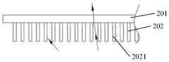
本公开至少一实施例提供一种导光组件,图1为本实施例提供的导光组件的平面示意图,图2为图1中的导光组件沿A-A线的截面示意图。如图1和图2所示,该导光组件10包括以第一方向为法向依次贴合的第一棱镜片101、介质层102和第二棱镜片103;介质层102的光折射率小于第一棱镜片101的光折射率和第二棱镜片103的光折射率。At least one embodiment of the present disclosure provides a light guide assembly. FIG. 1 is a schematic plan view of the light guide assembly provided in this embodiment, and FIG. 2 is a schematic cross-sectional view of the light guide assembly taken along line A-A in FIG. 1 . As shown in FIG. 1 and FIG. 2 , the
第一棱镜片101包括光入射侧面1013以及彼此相对的第一平面1012和第一棱镜面1011,第一平面1012相对于第一棱镜面1011更靠近介质层102,即第一平面1012与介质层102相邻设置,第一棱镜面1011包括多个沿第二方向延伸的第一棱镜部1011A,该第二方向与光入射侧面平行。例如,多个第一棱镜部1011A沿第三方向并列平行排布,该第三方向与第二方向垂直。本实施例中,第一棱镜部1011A的延伸方向(图中示出的第二方向)是指垂直于第一棱镜部1011A主截面的方向。例如,第一棱镜部1011A的主截面可以为三角形等多边形,或者三角形等多边形的变形形状,例如三角形的角形成为倒圆角等。例如,可以在光入射侧面1013设置光源,从而光源发出的光可以从光入射侧面1013射入第一棱镜片101内。第一棱镜片101可以将以一定角度射入其第一棱镜面1011的光线由于全反射效应而反射至介质层102,以及将经第二棱镜片103反射的满足一定角度条件的光线出射。例如,第一棱镜片101与介质层102之间的全反射临界角度为第一角度,第一棱镜片101可以接收由光入射侧面1013入射的光线,并可以通过第一棱镜部1011A将与介质层102表面夹角不小于第一角度的光线全反射并减小该全反射光线与第一方向的夹角。(后面将详细介绍)The
第二棱镜片103包括彼此相对的第二平面1032和第二棱镜面1031,第二平面1032相对于第二棱镜面1031更靠近介质层102,即第二平面1032与介质层102相邻设置,第二棱镜面1031包括多个沿第二方向延伸的第二棱镜部1031A,第二棱镜部1031A具有反射面;例如,多个第二棱镜部1031A沿第三方向并列平行排布。例如,第二棱镜片103配置为可以使以小于第一角度的第二角度照射到介质层102表面且经介质层102入射至第二棱镜部1031A的光线,被第二棱镜部1031A的反射面向第一方向反射并从第一棱镜面1011出射,从而从导光组件10出射的光基本沿第一方向传播,例如光的出射方向与第一方向的夹角在0°-10°的范围内,又例如在0°-5°的范围内。The
需要注意的是,本实施例中,是以第一棱镜片101与介质层102之间的全反射临界角度作为第一角度,即一个参考数值来选择第二角度,并基于第二角度来配置第二棱镜部1031A的结构参数。例如第二角度小于第一角度的差值Δ的范围可以选择为0<Δ≤2α,该α可以为第一子棱镜面1011A1与第一平面1012的夹角α1。利用该参考数值配置的第二棱镜部1031A可以将以小于第一角度的第二角度照射到介质层102表面且经介质层102入射至第二棱镜部1031A的光被第二棱镜部1031A向第一方向反射。例如,本实施例中,在第一棱镜片101的调制下,第二角度在略小于第一角度的范围内(下面将详细描述)。因此,该第二角度可以基本上等于全反射临界角度,例如在小于全反射临界角度0~5°的范围内确定。鉴于全反射现象中,只要光入射角小于临界角度,就不会发生全反射,因此在一个示例中,选择第二角度小于且基本等于临界角度,此时为了计算方便选择临界角度本身来替代第二角度进行计算,但是应该理解的是,在该示例中第二角度依然是小于临界角度的,否则将产生光全反射。It should be noted that, in this embodiment, the critical angle of total reflection between the
当选定了第二角度,则以该第二角度照射到介质层102表面且经介质层102入射至第二棱镜部1031A的光被第二棱镜部1031A向第一方向反射来配置第二棱镜部,即第二角度是设计第二棱镜部1031A的棱镜面的参考值。即便入射光以入射角度略微偏离第二角度(例如略大或略小)且经介质层102入射至第二棱镜部1031A,那么由第二棱镜部1031A反射后的光也会略微偏离第一方向,然而由于第二角度仅略微小于第一角度,因此该偏离的数值也同样较小,因此实现了将出射光沿第一方向的准直效果。When the second angle is selected, the light irradiated on the surface of the
例如,第二棱镜部1031A的主截面也可以为三角形等多边形,或者三角形等多边形的变形形状,例如三角形的角形成为倒圆形等。For example, the main cross section of the
在该实施例中,第二方向和第三方向在第一棱镜片所在的平面内,相应地也可以在第二棱镜片所在的平面内,因此与第一方向垂直。In this embodiment, the second direction and the third direction are in the plane where the first prism sheet is located, and correspondingly may also be in the plane where the second prism sheet is located, so they are perpendicular to the first direction.
例如,如图3所示,第一棱镜部1011A包括第一子棱镜面1011A1,第一子棱镜面1011A1与第一平面1012的夹角为α1,例如,α1的范围为0°<α1≤10°,例如0°<α1≤3°,例如1°、2°或3°等。例如,夹角α1朝向第一棱镜片101的光入射侧面1013,即第一子棱镜面1011A1的内侧(朝向第一棱镜部1011A内部的一侧)朝向第一棱镜片101的光入射侧面1013设置。并且,在该示例中,以第二角度小于且基本等于临界角度为例进行说明。For example, as shown in FIG. 3 , the
例如,本实施例中,第一棱镜部1011A还包括第二子棱镜面1011A2,第二子棱镜面1011A2与第一子棱镜面1011A1相交,例如,第一子棱镜面1011A1的内侧(朝向第一棱镜部1011A内部的一侧)背向第一棱镜片101的光入射侧面1013设置。例如,第二子棱镜面1011A2所在平面与第一平面1012的夹角为α2,例如,α2的范围为15°≤α2≤90°,例如45°≤α2≤90°,例如,α2为30°、45°、55°、65°、75°、80°、85°或90°等。For example, in this embodiment, the
例如,本实施例中,介质层102夹置在第一棱镜片101和第二棱镜片102之间,可以为无机或有机透明材料。在一个示例中,介质层102的材料包括光学透明胶(OCA),可以用于将第一棱镜片101和第二棱镜片102粘附在一起。该光学透明胶的折射率小于第一棱镜片101的光折射率和第二棱镜片102的光折射率。例如,该光学透明胶的折射率约为1.2-1.4,例如1.3或1.4等。For example, in this embodiment, the
例如,本实施例中,第一棱镜片101和第二棱镜片102的折射率相同,在从而方便于第一棱镜片101和第二棱镜片102的棱镜部的角度设计。例如,第一棱镜片101和第二棱镜片102采用相同的材料制备,因此二者的折射率相同,该材料可以为玻璃或树脂等材料,其折射率约为1.5-1.8,例如1.6、1.7或1.8等。For example, in this embodiment, the
例如,本实施例中,第二棱镜部1031A包括第三子棱镜面1031A1,至少第三子棱镜面1031A1配置为反射面,例如可以通过在第三子棱镜面1031A1上镀覆反射层(例如金属铝薄层)实现。例如,第三子棱镜面1031A1所在平面与第二平面1032的夹角为α3朝向第一棱镜面101的光入射侧面1013,此时,第三子棱镜面1031A1的内侧(朝向第二棱镜部1031A内部的一侧)朝向第一棱镜片101的光入射侧面1013设置。例如,第三子棱镜面1031A1所在平面与第二平面1032的夹角α3可以通过下面公式1计算得到:For example, in this embodiment, the

其中,n1为所述第一棱镜片的折射率,n2为所述介质层的折射率,n3为所述第二棱镜片的折射率。Wherein, n1 is the refractive index of the first prism sheet, n2 is the refractive index of the dielectric layer, and n3 is the refractive index of the second prism sheet.
如此得到的夹角α3,可以使得以第二角度照射到介质层102表面且经介质层102入射至第二棱镜部1031A的光被第二棱镜部1031A向第一方向反射,即在图中垂直向上反射。The angle α3 obtained in this way can make the light irradiated on the surface of the
例如,本实施例中,第二棱镜部1031A还包括第四子棱镜面1031A2,第四子棱镜面1031A2与第三子棱镜面1031A1相交。例如,第四子棱镜面1031A2的内侧(朝向第二棱镜部1031A内部的一侧)朝向第一棱镜片101的光入射侧面1013设置,并且第四子棱镜面1031A2所在平面与第二平面1032的夹角为α4,例如α4的范围为30°≤α4≤90°,例如60°≤α4≤90°,例如,α4为40°、50°、60°、70°、80°、85°或90°等。For example, in this embodiment, the
例如,本实施例的一个示例中,第二棱镜部1031A的主截面形状为直角三角形,且直角三角形的斜边所在平面配置为第三子棱镜面1031A1。例如,第三子棱镜面1031A1主要用于将光线向第一方向准直。For example, in an example of this embodiment, the main cross-sectional shape of the
例如,在一个示例中,α1设置为2°,α2设置为45°,α3设置为27.5°,α4设置为70°。上述设置不仅可以达到较好的准直效果,还方便于导光组件各部分的制作。For example, inone example, α1 is set to2 °, α2 is set to45 °,α3 is set to 27.5°, and α4 is set to 70°. The above arrangement can not only achieve a better collimation effect, but also facilitate the fabrication of each part of the light guide assembly.
例如,本实施例中,如图2所示,第二棱镜部1031A的表面还可以具有保护层111,以防止第二棱镜部1031A产生磨损。例如,保护层111的材料为树脂材料。For example, in this embodiment, as shown in FIG. 2 , the surface of the
例如,图3还示出了本实施例提供的导光组件进行光准直的示意图。如图3所示,该示例中,设定第一棱镜片101与第二棱镜片103的折射率相同,且第一棱镜片101和第二棱镜片103与介质层102之间的全反射临界角度均为θ(第一角度)。第一棱镜片101的光入射侧面1013设置有光源110,光源110例如为发光二极管(LED)等发光结构,该发光结构例如沿光入射侧面1013呈线性排布。例如,光源110包括LED以及围绕LED设置的反射壳体,使得其构成伯郎体光源,可以经第一棱镜片101的光入射侧面1013以预定角度(或角度范围)向第一棱镜片101内相对均匀地发射光,使得入射光可以在第一棱镜片101内全反射,从而可以从光入射侧面向与该光入射侧面相对的另一侧传播。For example, FIG. 3 also shows a schematic diagram of light collimation performed by the light guide assembly provided in this embodiment. As shown in FIG. 3 , in this example, the refractive indices of the
在上述情况下,当光源110发出的光束(图中的箭头所示)从第一棱镜片101的光入射侧面进入第一棱镜片101,例如入射到第一棱镜片101与介质层102的交界处A点时,若光线与第一方向,即图中的竖直方向,之间的夹角θ1<θ时,光线会经由介质层102进入第二棱镜片103,并由第二棱镜片103向第一方向或朝向第一方向的方向反射,这些光被第三子棱镜面1031A1,例如被调制为基本沿第一方向传播的准直光线(参考E点的准直路径)。In the above situation, when the light beam (shown by the arrow in the figure) emitted by the
另一方面,若光线与第一方向夹角θ1>θ时(图3中示出的情况),光线在A点发生全反射,并返回到第一棱镜片101的第一棱镜面1011,例如第一棱镜部1011A上的B点,第一棱镜片101的第一棱镜部1011A在将光线反射的同时可以减小光线与第一方向的夹角,此时光线经过B点全反射后光线角度与第一方向的夹角减小为θ3,且θ3=θ1-2α1,即第一棱镜部1011A将光线与第一方向的夹角减小的数值与朝向第一棱镜片101的光入射侧面1013的第一子棱镜面1011A1与第一平面1012的夹角α1有关,例如每次减小2α1。当角度θ3减小为θ3<θ时,光线可从C点进入介质层102并由D点进入第二棱镜片103,最终由第三子棱镜面1031A1的E点调制为沿第一方向传播的准直光线;若θ3的角度在经第一棱镜片101的反射后依然大于θ,光线会继续在第一棱镜片101内发生全反射,并再次通过第一棱镜片101的第一棱镜部1011A的反射作用而减小与第一方向之间的夹角,最终在θ3减小为小于θ时,光线即可进入第二棱镜片103并被调制为沿第一方向传播的准直光线。On the other hand, if the included angle θ1 > θ between the light ray and the first direction (the case shown in FIG. 3 ), the light ray is totally reflected at point A and returns to the
在本实施例的另一个示例中,选择第二角度为比临界角度(即第一角度)小α1,然后基于该第二角度照射到介质层表面且经介质层入射至第二棱镜部的光被第二棱镜部向第一方向反射为条件,来计算第三子棱镜面1031A1与第二平面1032的夹角为α3。该示例中,第一棱镜片101和第二棱镜片102的折射率相同,由于第二角度为比临界角度(即第一角度)小α1,则根据公式1可以得到:In another example of this embodiment, the second angle is selected to be α1 smaller than the critical angle (ie, the first angle), and then the light irradiated on the surface of the dielectric layer and incident on the second prism portion through the dielectric layer is based on the second angle The angle between the third sub-prism surface 1031A1 and the

仍然参考图3,当光源110发出的光束(图中的箭头所示)从第一棱镜片101的光入射侧面进入第一棱镜片101,例如入射到第一棱镜片101与介质层102的交界处A点时,若光线与第一方向,即图中的竖直方向,之间的夹角θ1<θ时,光线会经由介质层102进入第二棱镜片103,并由第二棱镜片103向第一方向或朝向第一方向的方向反射,这些光被第三子棱镜面1031A1,例如被调制为基本沿第一方向传播的准直光线(参考E点的准直路径)。Still referring to FIG. 3 , when the light beam (indicated by the arrow in the figure) emitted by the
另一方面,若光线与第一方向夹角θ1>θ时(图3中示出的情况),光线在A点发生全反射,并返回到第一棱镜片101的第一棱镜面1011,例如第一棱镜部1011A上的B点,第一棱镜片101的第一棱镜部1011A在将光线反射的同时可以减小光线与第一方向的夹角,此时光线经过B点全反射后光线角度与第一方向的夹角减小为θ3,且θ3=θ1-2α1,即第一棱镜部1011A将光线与第一方向的夹角减小的数值与朝向第一棱镜片101的光入射侧面1013的第一子棱镜面1011A1与第一平面1012的夹角α1有关,例如每次减小2α1。当角度θ3减小为θ3<θ时,光线可从C点进入介质层102并由D点进入第二棱镜片103,最终由第三子棱镜面1031A1的E点调制为沿第一方向传播的准直光线;若θ3的角度在经第一棱镜片101的反射后依然大于θ,光线会继续在第一棱镜片101内发生全反射,并再次通过第一棱镜片101的第一棱镜部1011A的反射作用而减小与第一方向之间的夹角,最终在θ3减小为小于θ时,光线即可进入第二棱镜片103并被调制为沿第一方向传播的准直光线。在该示例中,由于选择第二角度比第一角度(即θ)小于α1,因此在上述角度θ3以步长2α1逐渐减小至小于第一角度θ时,光线可经由介质层102进入第二棱镜片103,并且在第二棱镜部的第三子棱镜面1031A1的E点反射的光与第一方向的夹角小于α1,有助于改善获得的准直光线的准直程度。On the other hand, if the included angle θ1 > θ between the light ray and the first direction (the case shown in FIG. 3 ), the light ray is totally reflected at point A and returns to the
例如,本实施例中,如图2所示,第一棱镜面1011还可以包括多个第一平面部1011B,并分别位于相邻的第一棱镜部1011A之间。本实施例中,第一棱镜面1011中的多个第一棱镜部1011A之间间隔有第一平面部1011B,即本实施例的多个第一棱镜部1011A采用不连续设置方式,由于第一平面部1011B无法对射入第一棱镜片101的光线的角度进行调节,因此光线会继续在第一棱镜片101内发生全反射,并再次通过第一棱镜片101的第一棱镜部1011A的反射作用而减小与第一方向之间的夹角,直至光线经第一棱镜部1011A调制后与第一方向的角度减小为小于θ,此时光线可以射入第二棱镜片103,并经第二棱镜片103的准直后出射。因此,本实施例中,可以通过设置不同位置处第一棱镜部1011A的宽度以及间距或者第一平面部1011B的宽度以及间距等来调整对光进行准直的均匀性。For example, in this embodiment, as shown in FIG. 2 , the
例如,本实施例中,第一棱镜部1011A为条状时,至少两个第一棱镜部1011A在第三方向上的宽度不同;或者,至少两个第一平面部1011B在第三方向上的宽度不同;或者,至少两个第一棱镜部1011A在第三方向上的宽度不同的同时,至少两个第一平面部1011B在第三方向上的宽度也不同。For example, in this embodiment, when the
例如,第一棱镜片101的光入射侧面1013位置处设置光源110,此时,例如图4A所示,距离光入射侧面1013越近的第一棱镜部1011A的宽度d1越小,第一平面部1011B的宽度d2均相同;或者,如图4B所示,距离光入射侧面1013越近的第一平面部1011B的宽度d2越大,第一棱镜部1011A的宽度d1均相同;或者,如图4C所示,距离光入射侧面1013越近的第一棱镜部1011A的宽度d1越小的同时,距离光入射侧面1013越近的第一平面部1011B的宽度d2越大。For example, the
本实施例中,由于距离光源110越近的位置光线越充足,而距离光源110越远的位置光线越稀疏;因此,在距离光源110越近的位置设置排列较疏的第一棱镜部1011A,而在距离光源110越远的位置设置排列较密的第一棱镜部1011A可以使得第一棱镜部1011A在距离光源110越近的位置反射较少的光线,而在距离光源110越远的位置反射较多的光线,从而第二棱镜片在距离光源110越近的位置准直较多的光线,而在在距离光源110越远的位置准直较少的光线,因此可以调节导光组件不同位置处出射光的均匀性,进而改善导光组件的亮度均匀性。In this embodiment, since the position closer to the
例如,可以运用光学模拟软件(例如Lighttools等)对第一棱镜部1011A和第一平面部1011B的宽度等数值进行优化,例如以第一棱镜部1011A和/或第一平面部1011B的宽度间距为变量,设定一个亮度均匀性的目标函数,通过计算获得第一棱镜部1011A和第一平面部1011B的宽度等数值的优化参数,例如在Lighttools中采用BPO(Backlight PatternOptimization)模块对参数进行迭代优化,最终获得优化后的参数,在该参数设置下,导光组件的出光亮度更加均匀。For example, optical simulation software (such as Lighttools, etc.) can be used to optimize numerical values such as the width of the
本实施例中,当第一棱镜部1011A之间间隔有第一平面部1011B的情况下,如图3所示,从导光组件出射的光可能从第一棱镜部1011A出射,例如从G点出射,也可能从第一平面部1011B出射,例如从F点出射。当光线从第一平面部1011B出射时,由于出射光基本与第一平面部1011B垂直,因此第一平面部1011B基本不会改变出射光的传播方向;此外,当光线从第一棱镜部1011A出射时,由于第一棱镜部1011A与第一平面1012的夹角α1较小,例如0°<α1≤3°,因此经第一棱镜部1011A出射的光的角度改变也较小,设定该改变的角度为γ,则:In this embodiment, when a
γ=arc sin(n1×sinα1)-α1γ=arc sin(n1×sinα1 )-α1
其中,n1为第一棱镜片101和第二棱镜片103的折射率,α1为第一棱镜部1011A与第一平面1012的夹角。由于γ的角度较小,因此该出射光也可视为基本沿第一方向传播。Wherein, n1 is the refractive index of the
例如,本实施例中,如图5A所示,第一棱镜部1011A还可以为块状,并且第一棱镜部1011A的设置密度沿远离光入射侧面1013的方向(即图中从左向右的水平方向)增大。例如,第一棱镜面1101上除第一棱镜部1011A外的部分均为第一平面部1011B。本实施例中,第一棱镜部1011A的设置方式可以是规则的阵列排布,也可以是不规则的排布,本实施例对此不做限定。For example, in this embodiment, as shown in FIG. 5A , the
例如,图5B示出了一个示例中块状的第一棱镜部1011A的示意图。例如,图5B中从左至右依次为第一棱镜部1011A的俯视图以及该俯视图沿B-B线和A-A线的截面图。该示例中,例如第一棱镜部1011A的两条主边长度d3和d4均为45μm,沿B-B线的截面为第一棱镜部1011A的主截面,并且夹角α1,即第一棱镜部1011A的第一子棱镜面与第一平面的夹角为2°,夹角为α2,即第二子棱镜面与第一平面的夹角为45°。第一棱镜部1011A的沿A-A的截面中,夹角为α5为45°。在本实施例的其他示例中,块状的第一棱镜部1011A的各参数可以根据需求进行选择,本实施对此不做限定。For example, FIG. 5B shows a schematic diagram of the block-shaped
本实施例中,多个第二棱镜部1031A例如可以在第二棱镜面1031上连续设置,也即相邻的两个第二棱镜部的侧面彼此相交,从而可以校准更多的光线,提高光利用率。In this embodiment, a plurality of
本公开实施例提供的导光组件可以在第三方向上将光转变为基本沿第一方向准直的出射光,并且可以通过对棱镜部参数的优化来调节导光组件的出光均匀性,使得经导光组件出射的光的亮度更高并且亮度更加均匀。The light guide assembly provided by the embodiment of the present disclosure can convert light in the third direction into outgoing light that is substantially collimated along the first direction, and can adjust the light outgoing uniformity of the light guide assembly by optimizing the parameters of the prism part, so that the The light emitted from the light guide assembly has higher brightness and more uniform brightness.
本公开至少一实施例提供一种光准直组件,图6为本实施例提供的光准直组件的平面示意图;图7A为图6中的光准直组件沿A-A线的截面示意图;图7B为图6中的光准直组件沿B-B线的截面示意图。At least one embodiment of the present disclosure provides an optical collimation assembly. FIG. 6 is a schematic plan view of the optical collimation assembly provided in this embodiment; FIG. 7A is a schematic cross-sectional view of the optical collimation assembly in FIG. 6 along line A-A; FIG. 7B It is a schematic cross-sectional view of the light collimation assembly along the line B-B in FIG. 6 .
如图6-图7B所示,该光准直组件20包括上述任一的导光组件10和准直件201,准直件201与导光组件10沿第一方向叠层设置,且设置在靠近导光组件10的设置有第一棱镜片的一侧;该导光组件10可以将光线在第三方向上传播的部分沿第一方向准直出射光;准直件201配置为接收由导光组件10的第一棱镜片出射的光线,并将光线沿第二方向上传播的部分向第一方向准直并出射。As shown in FIG. 6-FIG. 7B, the
例如,本实施例中,准直件201包括光栅层202,光栅层202包括沿第三方向延伸的光栅条2021。光栅条2021可以对光起到调制作用。For example, in this embodiment, the
例如,本实施例中,光栅层202可以设置在准直件201的靠近导光组件的一侧或者远离导光组件的一侧。例如,图7B中示出了光栅层202设置在准直件201的远离导光组件的一侧的情况,当光栅层202设置在准直件201的靠近导光组件的一侧时,即采用如图8A所示的设置方式。For example, in this embodiment, the
例如,光栅条2021沿第二方向的横截面为梯形,并且光栅条2021的侧表面具有反射层。如图7B所示,光栅层202设置在准直件201的远离导光组件的一侧,光栅条2021的侧表面具有反射层(例如镀覆的金属铝薄层),而光栅条2021的顶部和底部为透过层。当光线射入光栅条2021的内表面时(例如图中左侧的光线),光线会被光栅条2021的反射层多次反射,最终射入导光组件10,并经过导光组件10的调制后重新返回准直件201。当光线射入光栅条2021的外表面时(例如图中右侧的光线),光线经过截面为梯形的光栅条2021进行反射,该反射可以将光向第一方向准直,例如减小光线与第一方向的角度,因此可以提高光线沿第一方向的准直度。For example, the cross section of the
例如,当光栅层202设置在准直件201的远离导光组件的一侧时,即将图7B中的光栅层202替换为如图8A中的光栅层202时,光栅条2021的侧表面具有反射层,而光栅条2021的顶部和底部为透过层。此时,当光线射入光栅条2021的外表面时(例如图中左侧的光线),光线会在光栅条2021的侧表面发生多次反射,然后射入导光组件10,并经过导光组件10的调制后重新返回准直件201。当光线光线射入光栅条2021的内表面时(例如图中右侧的光线),光线经截面为梯形的光栅条2021进行反射,该反射可以将光线向第一方向准直,例如减小光线与第一方向的角度,因此可以提高光沿第一方向的准直度。For example, when the
例如,本实施例中,光栅条2021沿第二方向的横截面还可以为矩形,并且光栅条2021的材料为吸光材料。For example, in this embodiment, the cross section of the
例如,将图7B中的光栅层202替换为如图8B中的光栅层202时,该示例中,截面为矩形的光栅条2021具有吸光性,因此射入光栅条2021表面的光线(例如图中左侧的光线)会被光栅条2021吸收,而不会出射;而没有射入光栅条2021的光线(例如图中右侧的光线)可以透过准直件201出射,因此与第一方向夹角较小的光线可以出射,从而可以获得沿第一方向的准直光。本实施例中,由于部分光被光栅条2021吸收,因此经准直件201出射的光的亮度可能较低,此时,可以通过增加棱镜片等方式进行增量。当光栅条2021截面为矩形时,无论光栅层202设置在准直件201的远离导光组件的一侧还是光栅层202设置在准直件201的靠近导光组件的一侧,光栅条2021的准直原理相同,因此不再分别描述。For example, when the
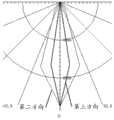
在本公开一个实施例提供的光准直组件中,导光组件的第一棱镜片101的第一子棱镜面1011A1与第一平面1012的夹角α1为0.5°,第二子棱镜面1011A2与第一平面1012的夹角α2为90°;第二棱镜片的第三子棱镜面1031A1与第二平面1032的夹角α3为57.5°,第二棱镜片的第四子棱镜面1031A2与第二平面1032的夹角α4为90°;准直件201包括的光栅条2021的横截面为梯形,并且梯形光栅条2021的高度为0.03mm,梯形光栅条2021的宽度为0.01mm,梯形光栅条2021之间的距离为0.02mm,梯形光栅条2021的底角为80°,并且光栅条2021的侧表面具有反射层。在上述参数下,经过对测试,如图9A所示,在第三方向上,经光准直组件调制后沿第一方向准直出射光的半亮度角约为±10°,在第二方向上,经光准直组件调制后沿第一方向准直出射光的半亮度角约为±23°,并且具有截止角,例如在第二方向以及第三方向上的截止角在约±50°的范围内。半亮度角指的是光亮度为最高亮度一半时的角度,可用于评价光的准直度,半亮度角越小,光的准直度越高。截止角是指光亮度基本为0或者光亮度小于最高亮度5%时的角度。In the light collimation assembly provided by an embodiment of the present disclosure, the angle α1 between thefirst sub-prism surface 1011A1 of the
在本公开另一个实施例提供的光准直组件中,导光组件的参数与上述相同;即导光组件的第一棱镜片101的第一子棱镜面1011A1与第一平面1012的夹角α1为0.5°,第二子棱镜面1011A2与第一平面1012的夹角α2为90°;第二棱镜片的第三子棱镜面1031A1与第二平面1032的夹角α3为57.5°,第二棱镜片的第四子棱镜面1031A2与第二平面1032的夹角α4为90°;与上述不同的是,准直件201包括的光栅条2021的横截面为矩形,此时,矩形光栅条2021的高度为0.03mm,矩形光栅条2021的宽度为0.01mm°,矩形光栅条2021之间的距离为0.02mm,并且光栅条2021包括吸光材料。在上述参数下,经过测试,如图9B所示,在第三方向上,经光准直组件调制后沿第一方向准直出射光的半亮度角约为±9°,在第二方向上,经光准直组件调制后沿第一方向准直出射光的半亮度角约为±19°,并且具有截止角,例如在第二方向以及第三方向上的截止角在约±40°的范围内。In the light collimation assembly provided by another embodiment of the present disclosure, the parameters of the light guide assembly are the same as above; that is, the angle α between the first sub-prism surface 1011A1 of the
可见,本公开实施例提供的光准直组件可以在第二方向和第三方向上同时实现对光的准直,即可以实现对光的二维准直。另外,通过对光准直组件中各个部件的参数的优化,可以使得从光准直组件出射的光在沿第一方向准直的同时,出射光的亮度更高,并且更加均匀。It can be seen that the light collimation assembly provided by the embodiments of the present disclosure can realize the collimation of the light in the second direction and the third direction at the same time, that is, the two-dimensional collimation of the light can be realized. In addition, by optimizing the parameters of each component in the light collimation assembly, the light emitted from the light collimation assembly can be collimated along the first direction, and the brightness of the emitted light is higher and more uniform.
另一方面,由于常规设计通常采用多个反射片来调整光线的传播路径,因此反射片的设置复杂,并需要通过精密的光路设计,而本公开实施例提供的光准直组件通过对棱镜微结构的设计减少常规设计中对反射片的使用,使光准直组件的结构更加简单。On the other hand, since conventional designs usually use multiple reflective sheets to adjust the propagation path of light, the setting of the reflective sheets is complicated and requires precise optical path design. The design of the structure reduces the use of the reflective sheet in the conventional design, so that the structure of the light collimation component is simpler.
本公开至少一实施例提供一种背光模组,如图10所示,该背光模组100包括上述任一的导光组件10或上述任一的光准直组件20。At least one embodiment of the present disclosure provides a backlight module. As shown in FIG. 10 , the
例如,本实施例提供的背光模组还可以包括光源110,光源110设置在导光组件10中第一棱镜片101的光入射侧面1013。光源110例如包括多个彼此并列设置的LED等发光结构,该发光结构例如沿光入射侧面1013呈线性排布。该光源也可以为冷阴极荧光灯(CCFL)等线性光源。For example, the backlight module provided in this embodiment may further include a
例如,第一棱镜部1011A的结构为条状时,距离光源110越近的第一棱镜部1011A的宽度越小;或者,距离光源110越近的第一平面部1011B的宽度越大;或者,距离光源110越近的第一棱镜部1011A的宽度越小的同时,距离光源110越近的第一平面部1011B的宽度越大。该设计可以调节导光组件不同位置处出射光的均匀性,进而可以改善背光模组的亮度均匀性。For example, when the structure of the
本公开实施例提供的背光模组的出射光为准直光,并且该背光模组对光源110的利用率较高,因此可以降低能耗。The emitted light of the backlight module provided by the embodiment of the present disclosure is collimated light, and the utilization rate of the
本公开至少一实施例提供一种显示装置,如图11所示,显示装置200包括上述任一的背光模组100。显示装置200可以为手机、平板电脑、电视机、显示器、笔记本电脑、数码相框、导航仪等任何具有显示功能的产品或部件。本实施例中,显示装置200的显示能耗较低,并且出光均匀。At least one embodiment of the present disclosure provides a display device. As shown in FIG. 11 , the
例如,由于显示装置200的出射光具有准直性,因此显示装置200可以实现智能显示,例如具有防偷窥,显示高动态范围图像(HDR)等特点,以满足不同种类显示装置的功能需求,例如可以应用于VR显示、车载显示、3D显示等具有特定使用距离和特定倾角的显示装置中。For example, since the emitted light of the
还有以下几点需要说明:There are a few more points to note:
(1)本公开实施例附图只涉及到与本公开实施例涉及到的结构,其他结构可参考通常设计。(1) The accompanying drawings of the embodiments of the present disclosure only relate to the structures involved in the embodiments of the present disclosure, and other structures may refer to general designs.
(2)为了清晰起见,在用于描述本公开的实施例的附图中,层或区域的厚度被放大或缩小,即这些附图并非按照实际的比例绘制。可以理解,当诸如层、膜、区域或基板之类的元件被称作位于另一元件“上”或“下”时,该元件可以“直接”位于另一元件“上”或“下”或者可以存在中间元件。(2) In the drawings for describing the embodiments of the present disclosure, the thicknesses of layers or regions are exaggerated or reduced for clarity, ie, the drawings are not drawn on actual scale. It will be understood that when an element such as a layer, film, region or substrate is referred to as being "on" or "under" another element, it can be "directly on" or "under" the other element, or Intermediate elements may be present.
(3)在不冲突的情况下,本公开的实施例及实施例中的特征可以相互组合以得到新的实施例。(3) The embodiments of the present disclosure and the features in the embodiments may be combined with each other to obtain new embodiments without conflict.
以上所述,仅为本公开的具体实施方式,但本公开的保护范围并不局限于此,任何熟悉本技术领域的技术人员在本公开揭露的技术范围内,可轻易想到变化或替换,都应涵盖在本公开的保护范围之内。因此,本公开的保护范围应以权利要求的保护范围为准。The above are only specific embodiments of the present disclosure, but the protection scope of the present disclosure is not limited to this. should be included within the scope of protection of the present disclosure. Therefore, the protection scope of the present disclosure should be subject to the protection scope of the claims.
Claims (18)
Priority Applications (2)
| Application Number | Priority Date | Filing Date | Title |
|---|---|---|---|
| CN201811257793.XACN109212660B (en) | 2018-10-26 | 2018-10-26 | Light guide assembly, light collimation assembly, backlight module and display device |
| US16/527,304US10761259B2 (en) | 2018-10-26 | 2019-07-31 | Light guide assembly, light collimation assembly, backlight module and display device |
Applications Claiming Priority (1)
| Application Number | Priority Date | Filing Date | Title |
|---|---|---|---|
| CN201811257793.XACN109212660B (en) | 2018-10-26 | 2018-10-26 | Light guide assembly, light collimation assembly, backlight module and display device |
Publications (2)
| Publication Number | Publication Date |
|---|---|
| CN109212660A CN109212660A (en) | 2019-01-15 |
| CN109212660Btrue CN109212660B (en) | 2020-01-24 |
Family
ID=64997583
Family Applications (1)
| Application Number | Title | Priority Date | Filing Date |
|---|---|---|---|
| CN201811257793.XAActiveCN109212660B (en) | 2018-10-26 | 2018-10-26 | Light guide assembly, light collimation assembly, backlight module and display device |
Country Status (2)
| Country | Link |
|---|---|
| US (1) | US10761259B2 (en) |
| CN (1) | CN109212660B (en) |
Families Citing this family (12)
| Publication number | Priority date | Publication date | Assignee | Title |
|---|---|---|---|---|
| CN111696446B (en)* | 2019-03-14 | 2023-08-04 | 诚屏科技股份有限公司 | Multi-screen display device |
| CN109765725B (en)* | 2019-03-26 | 2021-04-06 | 合肥京东方光电科技有限公司 | Collimation film, collimation backlight module, display module and display device |
| CN110658583A (en) | 2019-11-06 | 2020-01-07 | 合肥京东方光电科技有限公司 | Light guide plate, backlight module and display device |
| CN112946951A (en) | 2019-12-11 | 2021-06-11 | 中强光电股份有限公司 | Backlight module and display device |
| CN111061089B (en)* | 2019-12-13 | 2021-04-27 | 武汉华星光电技术有限公司 | Display device |
| CN111045256B (en)* | 2020-01-06 | 2023-03-10 | 京东方科技集团股份有限公司 | Backlight module and display device |
| CN111123426A (en)* | 2020-01-22 | 2020-05-08 | 马鞍山晶智科技有限公司 | Transparent light source system for display device |
| CN111624815B (en)* | 2020-06-29 | 2022-05-31 | 京东方科技集团股份有限公司 | A backlight module and display device |
| CN112965228B (en)* | 2021-03-19 | 2023-01-31 | 重庆京东方显示照明有限公司 | Anti-peeping film, display panel and display device |
| CN113219731B (en)* | 2021-05-21 | 2022-08-12 | 厦门天马微电子有限公司 | Backlight module and display device |
| CN114815036B (en)* | 2022-05-20 | 2024-05-31 | 深圳市高亮光光电科技有限公司 | Light guide plate, light guide plate assembly and light guide plate manufacturing method |
| CN118112708A (en) | 2022-11-29 | 2024-05-31 | 财团法人工业技术研究院 | Light source module |
Citations (7)
| Publication number | Priority date | Publication date | Assignee | Title |
|---|---|---|---|---|
| CN101526691A (en)* | 2008-03-04 | 2009-09-09 | 中强光电股份有限公司 | Optical film material of side light type backlight module |
| CN102588835A (en)* | 2012-02-08 | 2012-07-18 | 苏州晶智科技有限公司 | Novel backlight module for liquid crystal display |
| CN103150062A (en)* | 2012-10-31 | 2013-06-12 | 友达光电股份有限公司 | Touch control display device |
| CN103226261A (en)* | 2013-03-26 | 2013-07-31 | 苏州晶智科技有限公司 | Two-dimensional collimating backlight module used for LCD (liquid crystal display) |
| CN103235446A (en)* | 2013-04-18 | 2013-08-07 | 中国科学院苏州纳米技术与纳米仿生研究所 | Backlight module for liquid crystal display |
| CN103744229A (en)* | 2013-12-12 | 2014-04-23 | 中国电子科技集团公司第五十五研究所 | Backlight angle control method based on refraction index matching |
| KR20160059170A (en)* | 2014-11-18 | 2016-05-26 | (주)이노큐디 | Composite Double Side Prism Sheet |
Family Cites Families (7)
| Publication number | Priority date | Publication date | Assignee | Title |
|---|---|---|---|---|
| US5303322A (en)* | 1992-03-23 | 1994-04-12 | Nioptics Corporation | Tapered multilayer luminaire devices |
| US20080079870A1 (en)* | 2004-03-29 | 2008-04-03 | Miyashita Kazuhiro | Small-angled, predetermined-positioned and predetermined-orientated light emitting device of backlight module of liquid crystal display |
| RU2482385C1 (en)* | 2009-03-06 | 2013-05-20 | Шарп Кабусики Кайся | Flat illumination device and display device containing it |
| TW201109739A (en)* | 2009-09-10 | 2011-03-16 | Core Flex Optical Suzhou Co Ltd | Brightness enhancement film and backlight module |
| WO2013005559A1 (en)* | 2011-07-06 | 2013-01-10 | シャープ株式会社 | Illumination device and display device |
| WO2013008577A1 (en)* | 2011-07-13 | 2013-01-17 | シャープ株式会社 | Illumination device and display device |
| US20140140091A1 (en)* | 2012-11-20 | 2014-05-22 | Sergiy Victorovich Vasylyev | Waveguide illumination system |
- 2018
- 2018-10-26CNCN201811257793.XApatent/CN109212660B/enactiveActive
- 2019
- 2019-07-31USUS16/527,304patent/US10761259B2/enactiveActive
Patent Citations (7)
| Publication number | Priority date | Publication date | Assignee | Title |
|---|---|---|---|---|
| CN101526691A (en)* | 2008-03-04 | 2009-09-09 | 中强光电股份有限公司 | Optical film material of side light type backlight module |
| CN102588835A (en)* | 2012-02-08 | 2012-07-18 | 苏州晶智科技有限公司 | Novel backlight module for liquid crystal display |
| CN103150062A (en)* | 2012-10-31 | 2013-06-12 | 友达光电股份有限公司 | Touch control display device |
| CN103226261A (en)* | 2013-03-26 | 2013-07-31 | 苏州晶智科技有限公司 | Two-dimensional collimating backlight module used for LCD (liquid crystal display) |
| CN103235446A (en)* | 2013-04-18 | 2013-08-07 | 中国科学院苏州纳米技术与纳米仿生研究所 | Backlight module for liquid crystal display |
| CN103744229A (en)* | 2013-12-12 | 2014-04-23 | 中国电子科技集团公司第五十五研究所 | Backlight angle control method based on refraction index matching |
| KR20160059170A (en)* | 2014-11-18 | 2016-05-26 | (주)이노큐디 | Composite Double Side Prism Sheet |
Also Published As
| Publication number | Publication date |
|---|---|
| US10761259B2 (en) | 2020-09-01 |
| CN109212660A (en) | 2019-01-15 |
| US20200132913A1 (en) | 2020-04-30 |
Similar Documents
| Publication | Publication Date | Title |
|---|---|---|
| CN109212660B (en) | Light guide assembly, light collimation assembly, backlight module and display device | |
| US11835804B2 (en) | Peep-proof film, backlight source and display device | |
| CN206975244U (en) | Light guide plate, backlight module and display device | |
| JP5193987B2 (en) | Light guide plate and backlight module | |
| JP4900439B2 (en) | Planar light source device and display device using the same | |
| CN108287438A (en) | Backlight module and display equipment | |
| CN101221265A (en) | light guide plate | |
| CN213843580U (en) | Light guide plate, backlight module and display device | |
| WO2020192300A1 (en) | Optical collimating assembly, backlight module, and display device | |
| KR102005651B1 (en) | Light guide plate, backlight module and display device | |
| JPWO2007015328A1 (en) | Surface light source device and prism sheet | |
| WO2010010694A1 (en) | Liquid crystal display | |
| KR20090090926A (en) | Backlight unit | |
| JP2019200862A (en) | Light guide plate, surface light source device, and display device | |
| KR20160083571A (en) | Super Directional Light Guide Film And Thin Film Type Back Light Unit For Flat Panel Display Using The Same | |
| TWI587052B (en) | Light source module and display | |
| WO2016082249A1 (en) | Light guide plate, backlight module and display | |
| CN108873144B (en) | Light guide device, backlight module and liquid crystal display | |
| JP3226648U (en) | Light guide plate, backlight module, and display device | |
| CN108153054A (en) | Backlight module and display device | |
| JP2012089304A (en) | Surface light source device and liquid crystal display device | |
| KR100738111B1 (en) | High power light guide plate, backlight unit and display using the same | |
| JP5282500B2 (en) | Optical element and backlight unit and display device using the same | |
| JP2016189299A (en) | Surface light source device and display device | |
| CN111273486A (en) | Light collimating device, backlight module and display panel |
Legal Events
| Date | Code | Title | Description |
|---|---|---|---|
| PB01 | Publication | ||
| PB01 | Publication | ||
| SE01 | Entry into force of request for substantive examination | ||
| SE01 | Entry into force of request for substantive examination | ||
| GR01 | Patent grant | ||
| GR01 | Patent grant |