CN109212538B - Time-of-flight depth mapping with disparity compensation - Google Patents
Time-of-flight depth mapping with disparity compensationDownload PDFInfo
- Publication number
- CN109212538B CN109212538BCN201810571820.4ACN201810571820ACN109212538BCN 109212538 BCN109212538 BCN 109212538BCN 201810571820 ACN201810571820 ACN 201810571820ACN 109212538 BCN109212538 BCN 109212538B
- Authority
- CN
- China
- Prior art keywords
- array
- sensing elements
- target scene
- distance
- image
- Prior art date
- Legal status (The legal status is an assumption and is not a legal conclusion. Google has not performed a legal analysis and makes no representation as to the accuracy of the status listed.)
- Active
Links
- 238000013507mappingMethods0.000titleabstractdescription23
- 230000004044responseEffects0.000claimsabstractdescription24
- 230000003287optical effectEffects0.000claimsabstractdescription17
- 238000003384imaging methodMethods0.000claimsabstractdescription10
- 238000000034methodMethods0.000claimsdescription19
- 230000005540biological transmissionEffects0.000claimsdescription7
- 238000012545processingMethods0.000claimsdescription7
- 230000008569processEffects0.000claimsdescription4
- 238000006073displacement reactionMethods0.000claims1
- 230000000694effectsEffects0.000description6
- 230000005855radiationEffects0.000description5
- 238000003491arrayMethods0.000description4
- 238000001514detection methodMethods0.000description4
- 230000008859changeEffects0.000description3
- 238000013461designMethods0.000description3
- 238000005516engineering processMethods0.000description3
- 238000013459approachMethods0.000description2
- 238000010586diagramMethods0.000description2
- 230000006870functionEffects0.000description2
- 238000005286illuminationMethods0.000description2
- 238000005259measurementMethods0.000description2
- 230000003247decreasing effectEffects0.000description1
- 230000001419dependent effectEffects0.000description1
- 238000002592echocardiographyMethods0.000description1
- 230000002708enhancing effectEffects0.000description1
- 230000004907fluxEffects0.000description1
- 239000011159matrix materialSubstances0.000description1
- 238000012986modificationMethods0.000description1
- 230000004048modificationEffects0.000description1
- 238000012552reviewMethods0.000description1
- 239000004065semiconductorSubstances0.000description1
- 230000035945sensitivityEffects0.000description1
- 230000001953sensory effectEffects0.000description1
- 230000001360synchronised effectEffects0.000description1
Images


Classifications
- G—PHYSICS
- G01—MEASURING; TESTING
- G01S—RADIO DIRECTION-FINDING; RADIO NAVIGATION; DETERMINING DISTANCE OR VELOCITY BY USE OF RADIO WAVES; LOCATING OR PRESENCE-DETECTING BY USE OF THE REFLECTION OR RERADIATION OF RADIO WAVES; ANALOGOUS ARRANGEMENTS USING OTHER WAVES
- G01S17/00—Systems using the reflection or reradiation of electromagnetic waves other than radio waves, e.g. lidar systems
- G01S17/02—Systems using the reflection of electromagnetic waves other than radio waves
- G—PHYSICS
- G01—MEASURING; TESTING
- G01S—RADIO DIRECTION-FINDING; RADIO NAVIGATION; DETERMINING DISTANCE OR VELOCITY BY USE OF RADIO WAVES; LOCATING OR PRESENCE-DETECTING BY USE OF THE REFLECTION OR RERADIATION OF RADIO WAVES; ANALOGOUS ARRANGEMENTS USING OTHER WAVES
- G01S7/00—Details of systems according to groups G01S13/00, G01S15/00, G01S17/00
- G01S7/48—Details of systems according to groups G01S13/00, G01S15/00, G01S17/00 of systems according to group G01S17/00
- G01S7/483—Details of pulse systems
- G01S7/486—Receivers
- G01S7/4865—Time delay measurement, e.g. time-of-flight measurement, time of arrival measurement or determining the exact position of a peak
- G—PHYSICS
- G01—MEASURING; TESTING
- G01S—RADIO DIRECTION-FINDING; RADIO NAVIGATION; DETERMINING DISTANCE OR VELOCITY BY USE OF RADIO WAVES; LOCATING OR PRESENCE-DETECTING BY USE OF THE REFLECTION OR RERADIATION OF RADIO WAVES; ANALOGOUS ARRANGEMENTS USING OTHER WAVES
- G01S17/00—Systems using the reflection or reradiation of electromagnetic waves other than radio waves, e.g. lidar systems
- G01S17/02—Systems using the reflection of electromagnetic waves other than radio waves
- G01S17/06—Systems determining position data of a target
- G01S17/08—Systems determining position data of a target for measuring distance only
- G01S17/10—Systems determining position data of a target for measuring distance only using transmission of interrupted, pulse-modulated waves
- G—PHYSICS
- G01—MEASURING; TESTING
- G01S—RADIO DIRECTION-FINDING; RADIO NAVIGATION; DETERMINING DISTANCE OR VELOCITY BY USE OF RADIO WAVES; LOCATING OR PRESENCE-DETECTING BY USE OF THE REFLECTION OR RERADIATION OF RADIO WAVES; ANALOGOUS ARRANGEMENTS USING OTHER WAVES
- G01S17/00—Systems using the reflection or reradiation of electromagnetic waves other than radio waves, e.g. lidar systems
- G01S17/02—Systems using the reflection of electromagnetic waves other than radio waves
- G01S17/06—Systems determining position data of a target
- G01S17/42—Simultaneous measurement of distance and other co-ordinates
- G—PHYSICS
- G01—MEASURING; TESTING
- G01S—RADIO DIRECTION-FINDING; RADIO NAVIGATION; DETERMINING DISTANCE OR VELOCITY BY USE OF RADIO WAVES; LOCATING OR PRESENCE-DETECTING BY USE OF THE REFLECTION OR RERADIATION OF RADIO WAVES; ANALOGOUS ARRANGEMENTS USING OTHER WAVES
- G01S17/00—Systems using the reflection or reradiation of electromagnetic waves other than radio waves, e.g. lidar systems
- G01S17/88—Lidar systems specially adapted for specific applications
- G01S17/89—Lidar systems specially adapted for specific applications for mapping or imaging
- G—PHYSICS
- G01—MEASURING; TESTING
- G01S—RADIO DIRECTION-FINDING; RADIO NAVIGATION; DETERMINING DISTANCE OR VELOCITY BY USE OF RADIO WAVES; LOCATING OR PRESENCE-DETECTING BY USE OF THE REFLECTION OR RERADIATION OF RADIO WAVES; ANALOGOUS ARRANGEMENTS USING OTHER WAVES
- G01S7/00—Details of systems according to groups G01S13/00, G01S15/00, G01S17/00
- G01S7/48—Details of systems according to groups G01S13/00, G01S15/00, G01S17/00 of systems according to group G01S17/00
- G01S7/483—Details of pulse systems
- G01S7/486—Receivers
- G01S7/4861—Circuits for detection, sampling, integration or read-out
- G01S7/4863—Detector arrays, e.g. charge-transfer gates
- H—ELECTRICITY
- H10—SEMICONDUCTOR DEVICES; ELECTRIC SOLID-STATE DEVICES NOT OTHERWISE PROVIDED FOR
- H10F—INORGANIC SEMICONDUCTOR DEVICES SENSITIVE TO INFRARED RADIATION, LIGHT, ELECTROMAGNETIC RADIATION OF SHORTER WAVELENGTH OR CORPUSCULAR RADIATION
- H10F30/00—Individual radiation-sensitive semiconductor devices in which radiation controls the flow of current through the devices, e.g. photodetectors
- H10F30/20—Individual radiation-sensitive semiconductor devices in which radiation controls the flow of current through the devices, e.g. photodetectors the devices having potential barriers, e.g. phototransistors
- H10F30/21—Individual radiation-sensitive semiconductor devices in which radiation controls the flow of current through the devices, e.g. photodetectors the devices having potential barriers, e.g. phototransistors the devices being sensitive to infrared, visible or ultraviolet radiation
- H10F30/22—Individual radiation-sensitive semiconductor devices in which radiation controls the flow of current through the devices, e.g. photodetectors the devices having potential barriers, e.g. phototransistors the devices being sensitive to infrared, visible or ultraviolet radiation the devices having only one potential barrier, e.g. photodiodes
- H10F30/225—Individual radiation-sensitive semiconductor devices in which radiation controls the flow of current through the devices, e.g. photodetectors the devices having potential barriers, e.g. phototransistors the devices being sensitive to infrared, visible or ultraviolet radiation the devices having only one potential barrier, e.g. photodiodes the potential barrier working in avalanche mode, e.g. avalanche photodiodes
- H—ELECTRICITY
- H10—SEMICONDUCTOR DEVICES; ELECTRIC SOLID-STATE DEVICES NOT OTHERWISE PROVIDED FOR
- H10F—INORGANIC SEMICONDUCTOR DEVICES SENSITIVE TO INFRARED RADIATION, LIGHT, ELECTROMAGNETIC RADIATION OF SHORTER WAVELENGTH OR CORPUSCULAR RADIATION
- H10F39/00—Integrated devices, or assemblies of multiple devices, comprising at least one element covered by group H10F30/00, e.g. radiation detectors comprising photodiode arrays
- H10F39/10—Integrated devices
- H10F39/103—Integrated devices the at least one element covered by H10F30/00 having potential barriers, e.g. integrated devices comprising photodiodes or phototransistors
Landscapes
- Physics & Mathematics (AREA)
- Engineering & Computer Science (AREA)
- Electromagnetism (AREA)
- Computer Networks & Wireless Communication (AREA)
- General Physics & Mathematics (AREA)
- Radar, Positioning & Navigation (AREA)
- Remote Sensing (AREA)
- Measurement Of Optical Distance (AREA)
- Optical Radar Systems And Details Thereof (AREA)
Abstract
Description
Translated fromChinese技术领域technical field
本发明整体涉及深度映射,具体地讲涉及用于基于飞行时间(ToF)的感测进行深度映射的设备和方法。The present invention relates generally to depth mapping, and more particularly to an apparatus and method for depth mapping based on time-of-flight (ToF) sensing.
背景技术Background technique
在许多深度映射系统(也称为3D映射或3D成像系统)中使用飞行时间(ToF)成像技术。在直接ToF技术中,光源诸如脉冲激光器朝向要被映射的场景引导光学辐射的脉冲,并且高速检测器感测从该场景反射的辐射的到达时间。(在本说明书和权利要求书的上下文中所使用的术语“光”和“照明”是指在可见范围、红外范围和紫外范围中的任何或所有范围中的光学辐射。)深度图中每个像素的深度值是得自输出脉冲的发射时间与从场景中对应点反射的辐射的到达时间之间的差值,这被称为光学脉冲的“飞行时间”。被反射回且被检测器接收的辐射脉冲也被称为“回波”。Time-of-flight (ToF) imaging techniques are used in many depth mapping systems (also known as 3D mapping or 3D imaging systems). In direct ToF technology, a light source, such as a pulsed laser, directs pulses of optical radiation towards the scene to be mapped, and a high-speed detector senses the arrival time of radiation reflected from the scene. (The terms "light" and "illumination" as used in the context of this specification and claims refer to optical radiation in any or all of the visible, infrared and ultraviolet ranges.) Each of the depth maps The depth value of a pixel is derived from the difference between the emission time of the output pulse and the arrival time of the radiation reflected from the corresponding point in the scene, which is called the "time of flight" of the optical pulse. The pulse of radiation that is reflected back and received by the detector is also called an "echo".
一些基于ToF的深度映射系统使用基于单光子雪崩二极管(SPAD)阵列的检测器。SPAD也称为盖革模式雪崩光电二极管(GAPD),是能够以数十皮秒量级的非常高的到达时间分辨率捕获各个光子的检测器。它们可在专用半导体工艺中或者在标准CMOS技术中制造。在单个芯片上制造的SPAD传感器阵列已在3D成像相机中进行了实验。Charbon等人在发表于TOF Range-Imaging Cameras(Springer-Verlag,2013)的“SPAD-Based Sensors”中提供了SPAD技术的综述。Some ToF-based depth-mapping systems use detectors based on single-photon avalanche diode (SPAD) arrays. SPADs, also known as Geiger-mode avalanche photodiodes (GAPDs), are detectors capable of capturing individual photons with very high time-of-arrival resolution on the order of tens of picoseconds. They can be fabricated in dedicated semiconductor processes or in standard CMOS technology. Arrays of SPAD sensors fabricated on a single chip have been experimented with in 3D imaging cameras. Charbon et al. provide a review of SPAD technology in "SPAD-Based Sensors" published in TOF Range-Imaging Cameras (Springer-Verlag, 2013).
为了实现有效检测,可将SPAD阵列与专用处理电路集成。例如,公开内容以引用方式并入本文的美国专利申请公布2017/0052065描述了一种包括第一阵列的感测元件(诸如SPAD)的感测设备,这些感测元件输出指示感测元件上单个光子的入射时间的信号。第二阵列的处理电路分别耦接至所述感测元件,并且包括选通发生器和存储器,选通发生器可变地在每个采集周期内为每个感测元件设置选通间隔的起始时间,存储器记录每个采集周期中每个感测元件上所述单个光子的入射时间。控制器处理每个感测元件的不同时间仓上相应计数的直方图,以推导和输出感测元件的相应到达时间值。For efficient detection, SPAD arrays can be integrated with dedicated processing circuits. For example, U.S. Patent Application Publication 2017/0052065, the disclosure of which is incorporated herein by reference, describes a sensing device that includes a first array of sensing elements, such as SPADs, whose outputs are indicative of individual The signal of the incident time of the photon. The processing circuitry of the second array is coupled to the sensing elements respectively and includes a gate generator and a memory, the gate generator variably sets the start of the gate interval for each sensing element in each acquisition cycle The memory records the incident time of the single photon on each sensing element in each acquisition cycle. The controller processes the histogram of the corresponding counts over different time bins for each sensing element to derive and output the corresponding time-of-arrival value for the sensing element.
发明内容Contents of the invention
下文描述的本发明的实施方案提供了改进的用于基于ToF的深度映射的设备和方法。Embodiments of the invention described below provide improved apparatus and methods for ToF-based depth mapping.
因此,根据本发明的一个实施方案提供了一种包括光源的光学感测设备,所述光源被配置为以相应角度朝目标场景发射一个或多个波束的光脉冲。感测元件阵列被配置为响应于感测元件上光子的入射而输出信号。光收集光学器件被配置为将目标场景成像到所述阵列上。控制电路被耦接为致动所述阵列的仅一个或多个所选定的区域中的感测元件,每个所选定的区域包含所述阵列的一部分中的相应一组感测元件,光收集光学器件将被这些波束中的一个波束照明的目标场景的对应区域成像到所述阵列的一部分中的相应一组感测元件上;并且响应于所述对应区域与设备的距离来调整所述相应一组的成员。Accordingly, according to one embodiment of the present invention there is provided an optical sensing device comprising a light source configured to emit one or more beams of light pulses towards a target scene at respective angles. The array of sensing elements is configured to output signals in response to the incidence of photons on the sensing elements. Light collection optics are configured to image a target scene onto the array. control circuitry coupled to actuate sensing elements in only one or more selected regions of the array, each selected region containing a respective set of sensing elements in a portion of the array, Light collection optics image a corresponding region of the target scene illuminated by one of the beams onto a corresponding set of sensing elements in the portion of the array; and adjust the corresponding region in response to the distance of the corresponding region from the device. members of the corresponding group.
在所公开的实施方案中,感测元件所输出的信号指示感测元件上光子的相应到达时间,并且控制电路被配置为处理所述信号以便基于所述到达时间来计算与目标场景中所述对应区域的距离。在一个实施方案中,感测元件包括单光子雪崩二极管(SPAD)。除此之外或另选地,控制电路被配置为将所述一组中的感测元件所输出的信号组合在一起,以便计算所述一组上光子的平均飞行时间。In disclosed embodiments, the signal output by the sensing element is indicative of the corresponding time of arrival of the photons on the sensing element, and the control circuit is configured to process the signal to calculate, based on the time of arrival, a correlation with that described in the target scene. The distance of the corresponding area. In one embodiment, the sensing element comprises a single photon avalanche diode (SPAD). Additionally or alternatively, the control circuit is configured to combine the signals output by the sensing elements in the set to calculate an average time-of-flight of photons on the set.
在一公开实施方案中,光源包括多个发射器,所述多个发射器被配置为同时朝目标场景的相应不同区域发射对应的多个所述波束。In a disclosed embodiment, the light source comprises a plurality of emitters configured to simultaneously emit a corresponding plurality of said beams toward respective different regions of the target scene.
在一个实施方案中,控制电路被配置为响应于所述距离而扩大所述阵列的所选定的区域,使得所选定的区域在所述对应区域位于设备附近时比在所述对应区域远离设备时包含更大数量的感测元件。In one embodiment, the control circuit is configured to expand the selected area of the array in response to the distance such that the selected area is farther away than the corresponding area when the corresponding area is located near the device. devices contain a greater number of sensing elements.
除此之外或另选地,该设备被配置为在从最小范围到最大范围的距离范围内感测从目标场景接收的光子,并且控制电路被配置为将所选定的区域的尺寸设置为足以包含在最大范围处场景的所述对应区域的被光收集光学器件投射到所述阵列上的第一图像,但小于在最小范围处场景的所述对应区域被光收集光学器件投射到所述阵列上的第二图像。Additionally or alternatively, the device is configured to sense photons received from the target scene over a distance range from a minimum range to a maximum range, and the control circuit is configured to set the size of the selected area to a first image projected onto the array by the light collection optics sufficient to contain the corresponding area of the scene at maximum extent, but smaller than the corresponding area of the scene at minimum extent projected by the light collection optics onto the array The second image on the array.
根据本发明的一个实施方案,还提供了一种包括光源的光学感测设备,所述光源被配置为沿传输轴朝目标场景发射一个或多个波束的光脉冲。感测元件阵列被配置为响应于感测元件上光子的入射而输出信号。光收集光学器件被配置为沿相对于所述传输轴横向偏移的接收轴将目标场景成像到所述阵列上。控制电路被耦接为致动所述阵列的仅一个或多个所选定的区域中的感测元件,每个所选定的区域包含所述阵列的一部分中的相应一组所述感测元件,光收集光学器件将被这些波束中的一个波束照明的目标场景的对应区域成像到所述阵列的一部分中的相应一组所述感测元件上,而响应于由于传输轴和接收轴之间的偏移导致的视差来设置所选定的区域的边界。According to an embodiment of the present invention, there is also provided an optical sensing device comprising a light source configured to emit light pulses of one or more beams towards a target scene along a transmission axis. The array of sensing elements is configured to output signals in response to the incidence of photons on the sensing elements. Light collection optics are configured to image a target scene onto the array along a receive axis that is laterally offset relative to the transmit axis. Control circuitry is coupled to actuate sensing elements in only one or more selected regions of the array, each selected region containing a respective set of the sensing elements in a portion of the array. elements, the light collection optics image a corresponding region of the target scene illuminated by one of these beams onto a corresponding set of said sensing elements in a portion of said array, in response to The parallax caused by the offset between them is used to set the boundaries of the selected area.
在本发明的一公开实施方案中,控制电路被配置为响应于所述对应区域与设备的距离来移位所述阵列的所选定的区域的边界,以便补偿所述视差。In a disclosed embodiment of the invention, the control circuit is configured to shift a boundary of a selected region of the array in response to a distance of the corresponding region from the device in order to compensate for the parallax.
除此之外或另选地,所述设备被配置为在从最小范围到最大范围的距离范围内感测从目标场景接收的光子,使得在最大范围处场景的所述对应区域的被光收集光学器件投射到所述阵列上的第一图像由于所述视差而相对于在最小范围处场景的所述对应区域的被光收集光学器件投射到所述阵列上的第二图像横向移位。控制电路被配置为将所选定的区域的边界设置成包含第一图像的全部,但只包含第二图像的一部分。Additionally or alternatively, the device is configured to sense photons received from a target scene over a distance range from a minimum range to a maximum range such that at the maximum range photons of said corresponding region of the scene are collected by light A first image projected by the optics onto the array is laterally displaced relative to a second image projected onto the array by the light collection optics of the corresponding region of the scene at a minimum extent due to the parallax. The control circuit is configured to set the boundary of the selected area to encompass all of the first image but only a portion of the second image.
根据本发明的一个实施方案,还提供了一种用于光学感测的方法,该方法包括以相应角度朝目标场景发射一个或多个波束的光脉冲。目标场景被成像到感测元件阵列,感测元件阵列被配置为响应于感测元件上光子的入射而输出信号。感测元件仅在所述阵列的一个或多个所选定的区域中被致动,每个所选定的区域包含所述阵列的一部分中的相应一组所述感测元件,被这些波束中的一个波束照明的目标场景的对应区域被成像到所述阵列的一部分中的相应一组所述感测元件上。所述相应一组的成员响应于所述对应区域与所述阵列的距离而被调整。According to an embodiment of the present invention, there is also provided a method for optical sensing, the method comprising emitting light pulses of one or more beams towards a target scene at corresponding angles. The target scene is imaged onto an array of sensing elements configured to output signals in response to the incidence of photons on the sensing elements. Sensing elements are actuated only in one or more selected regions of the array, each selected region containing a corresponding set of the sensing elements in a portion of the array, by the beams A corresponding region of the target scene illuminated by one of the beams is imaged onto a corresponding set of the sensing elements in a portion of the array. Membership of the respective set is adjusted in response to the distance of the corresponding area from the array.
在一些实施方案中,所述一个或多个波束沿传输轴被发射,而目标场景沿相对于传输轴横向偏移的接收轴被成像到所述阵列上,并且调整所述成员包括根据所述距离改变所述成员以便补偿传输轴和接收轴之间的视差。In some embodiments, the one or more beams are transmitted along a transmit axis, and the target scene is imaged onto the array along a receive axis laterally offset relative to the transmit axis, and adjusting the members includes according to the The distance changes the members in order to compensate for the parallax between the transmit and receive axes.
结合附图,从下文中对本发明的实施方案的详细描述将更完全地理解本发明,在附图中:The present invention will be more fully understood from the following detailed description of embodiments of the invention in conjunction with the accompanying drawings, in which:
附图说明Description of drawings
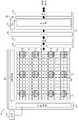
图1是根据本发明一实施方案的深度映射设备的示意性侧视图;Figure 1 is a schematic side view of a depth mapping device according to an embodiment of the present invention;
图2是根据本发明一实施方案的示意性地示出ToF检测阵列的框图。Figure 2 is a block diagram schematically illustrating a ToF detection array according to an embodiment of the present invention.
图3为根据本发明一实施方案的仅成像SPAD阵列的元件的反射激光点的示意性前视图;3 is a schematic front view of a reflected laser spot imaging only elements of a SPAD array according to an embodiment of the invention;
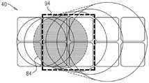
图4A-C是根据本发明一实施方案的在ToF检测阵列的操作中定义的一系列超像素的示意性前视图;并且4A-C are schematic front views of a series of superpixels defined in operation of a ToF detection array according to an embodiment of the invention; and
图5A-C是根据本发明另一实施方案的在ToF检测阵列的操作中定义的一系列超像素的示意性前视图。5A-C are schematic front views of a series of superpixels defined in operation of a ToF detection array according to another embodiment of the invention.
具体实施方式detailed description
概述overview
公开内容以引用方式并入本文的美国专利申请公布2017/0176579描述了一种基于ToF的深度映射系统,其中所传输的激光脉冲的回波被二维阵列的单光子时间敏感感测元件(诸如SPAD)感测。通过经由专用控制电路单独寻址每个SPAD,每个SPAD的灵敏度(包括接通/关断状态)由其特定反向p-n结高电压控制。在扫描期间的任何时刻,阵列的只有要接收来自所发射波束的反射照明的区域中的感测元件被致动。因此,感测元件只有在其信号提供有用信息时才被致动。这种方法既降低背景信号,从而増强信号与背景的比例,又降低检测器阵列的电力需求。U.S. Patent Application Publication 2017/0176579, the disclosure of which is incorporated herein by reference, describes a ToF-based depth mapping system in which echoes of transmitted laser pulses are detected by a two-dimensional array of single-photon time-sensitive sensing elements such as SPAD) sensing. The sensitivity of each SPAD, including on/off state, is controlled by its specific reverse p-n junction high voltage by individually addressing each SPAD via a dedicated control circuit. At any time during the scan, only the sensing elements in the area of the array that is to receive reflected illumination from the transmitted beam are actuated. Thus, the sensing element is only actuated when its signal provides useful information. This approach both reduces the background signal, thereby enhancing the signal-to-background ratio, and reduces the power requirements of the detector array.
在一些实施方案中,若干SPAD被分组在一起成为“超像素”,这意味着这些SPAD同时被致动,并且其由于入射光子而产生的脉冲被组合在一起以用于ToF测量的目的。在任何给定时间被致动的超像素是来自给定的被传输脉冲的反射光子预期要入射在上面的那些超像素。因此,如果被传输和被反射的波束紧密地聚焦,则被反射的脉冲将仅入射在单个SPAD或小的一组SPAD上,并且超像素需要仅包括几个相邻的SPAD。另一方面,当被反射的波束在SPAD阵列的较大面积上延伸时,使用较大的超像素是有利的。In some embodiments, several SPADs are grouped together into "superpixels," meaning that the SPADs are actuated simultaneously and their pulses due to incident photons are combined for ToF measurement purposes. The superpixels that are actuated at any given time are those on which reflected photons from a given transmitted pulse are expected to be incident. Therefore, if the transmitted and reflected beams are tightly focused, the reflected pulse will only be incident on a single SPAD or a small set of SPADs, and the superpixel needs to include only a few adjacent SPADs. On the other hand, using larger superpixels is advantageous when the reflected beam extends over a larger area of the SPAD array.
如果被传输的和被反射的脉冲的波束路径是同轴的,则在给定角度方向上从基于ToF的映射设备传输的脉冲将始终被反射回到阵列中的相同SPAD或相同一组SPAD,而不管与所述脉冲被反射自的所述场景中的对象的距离是如何。这种同轴布置通常决定使用波束组合器,这导致信号损耗并且强加其他设计约束。因此,在下文所述的实施方案中,传输器和接收器被并排定位,在它们各自的光轴之间具有偏移。A pulse transmitted from a ToF-based mapping device in a given angular direction will always be reflected back to the same SPAD or the same set of SPADs in the array if the beam paths of the transmitted and reflected pulses are coaxial, Regardless of the distance to objects in the scene from which the pulses are reflected. Such coaxial arrangements often dictate the use of beam combiners, which results in signal loss and imposes other design constraints. Thus, in the embodiments described below, the transmitter and receiver are positioned side by side, with an offset between their respective optical axes.
然而,传输器和接收器之间的偏移导致视差的问题:接收沿给定角度方向传输的脉冲的反射的SPAD或SPAD组将根据与所述脉冲入射到的所述场景中的区域的距离而变化。此外,在非同轴构型和同轴构型两者中,SPAD阵列上反射点的尺寸通常将由于散焦而随着距离而变化,并且具体而言,对于近距对象而言可能比对于远距对象而言更大。为了适应反射点的位置和尺寸的这些距离相关的变化,可以使用大的超像素,其将捕获基本上所有被反射的光子,而不管与对象的距离是如何。然而,这种方法増加了SPAD阵列中产生的功率消耗和噪声,因为与为了在任何给定距离处接收来自所述对象的所有被反射光子所实际需要的相比,明显更大数量的SPAD被致动。这个问题对于远距对象而言尤其严重,来自远距对象的被反射光信号相对较弱。However, the offset between transmitter and receiver leads to a problem of parallax: the SPAD or group of SPADs receiving a reflection of a pulse transmitted in a given angular direction will be distorted according to the distance from the area in the scene on which the pulse is incident. And change. Furthermore, in both non-coaxial and coaxial configurations, the size of the reflective spot on the SPAD array will generally vary with distance due to defocus, and may be more specific for close objects than for Larger for distant objects. To accommodate these distance-dependent variations in the location and size of the reflection point, large superpixels can be used that will capture essentially all reflected photons regardless of the distance to the object. However, this approach increases the power consumption and noise generated in the SPAD array, since a significantly greater number of SPADs are used than would actually be required to receive all reflected photons from the object at any given distance. actuate. This problem is especially severe for distant objects, from which the reflected light signal is relatively weak.
本文所述的本发明的实施方案通过提供动态超像素来解决这个问题,所述动态超像素根据与目标场景的距离来改变其配置。因此,要接收来自以给定角度传输的波束的反射光的超像素的位置被选择,并且可被移位,以根据对象距离来适应视差效应。除此之外或另选地,超像素的尺寸被设置,并且可増大或减小,以便处理被反射点尺寸的变化。Embodiments of the invention described herein address this problem by providing dynamic superpixels that change their configuration depending on distance from the target scene. Thus, the position of the superpixel to receive reflected light from a beam transmitted at a given angle is selected and can be shifted to accommodate parallax effects according to object distance. Additionally or alternatively, the size of the superpixels is set and may be increased or decreased to account for variations in reflected point size.
所公开的实施方案提供了一种光学感测设备,该光学感测设备包括光源和感测元件阵列。光源以相应角度朝目标场景发射一个或多个波束的光脉冲,并且光收集光学器件将目标场景成像到感测元件阵列上,感测元件响应于入射光子而输出信号。在下文所述的实施方案中,光源包括发射器阵列,但本发明的原理另选地可以必要的变更而应用于被扫描光束,如在上面提到的美国专利申请公布2017/0176579中那样。The disclosed embodiments provide an optical sensing device that includes a light source and an array of sensing elements. A light source emits one or more beams of light pulses toward a target scene at corresponding angles, and light collection optics image the target scene onto an array of sensing elements that output signals in response to incident photons. In the embodiments described below, the light source comprises an array of emitters, but the principles of the invention may alternatively be applied mutatis mutandis to a scanned light beam, as in the above-mentioned US Patent Application Publication 2017/0176579.
控制电路致动所述阵列的仅一个或多个所选定的区域中的感测元件,它们被定义为超像素。每个此类超像素包含所述阵列的一部分中的相应一组所述感测元件,光收集光学器件将被所发射波束之一照明的目标场景的对应区域成像到所述阵列的一部分中的相应一组所述感测元件上。控制电路根据所述对应区域与设备的距离来调整所述一组感测元件的成员。在一些实施方案中,这些调整包括扩大和缩小所述阵列的所选定的区域,使得所述超像素在所述对应区域位于设备附近时可比所述对应区域远离设备时包含更大数量的感测元件。Control circuitry actuates sensing elements in only one or more selected regions of the array, which are defined as superpixels. Each such superpixel comprises a respective set of said sensing elements in a portion of said array into which light collection optics image a corresponding region of a target scene illuminated by one of the emitted beams. on a corresponding set of sensing elements. A control circuit adjusts the membership of the set of sensing elements according to the distance of the corresponding area from the device. In some embodiments, these adjustments include expanding and shrinking selected regions of the array such that the superpixels contain a greater number of sensory pixels when the corresponding region is near the device than when the corresponding region is further away from the device. measuring components.
除此之外或另选地,在一些实施方案中,超像素边界可被设置并且可被移位以考虑视差,这是由于光收集光学器件的接收轴相对于光源的传输轴的横向偏移。(如上所述,传输轴和接收轴之间的偏移导致对应于给定超像素的场景的区域的图像随着所述区域与设备的距离而横向地移位)。在一些实施方案中,控制电路移位超像素的边界以便补偿这个视差,例如通过根据所述对应区域与设备的距离设置和移位超像素的边界来实现。在其他实施方案中,超像素的边界被设置以包含在对应于超像素的区域处于与设备相距最大范围处时被投射到阵列上的图像,而仅包含在所述场景的所述对应区域在最小范围处(在那里,预期所述阵列输出的信号总归将更强)时被投射到阵列上的图像的一部分。Additionally or alternatively, in some embodiments superpixel boundaries may be set and may be shifted to account for parallax due to lateral offset of the receive axis of the light collection optics relative to the transmit axis of the light source . (As mentioned above, the offset between the transmit and receive axes causes the image of a region of the scene corresponding to a given superpixel to shift laterally with the distance of that region from the device). In some embodiments, the control circuitry shifts the boundaries of the superpixels to compensate for this parallax, for example by setting and shifting the boundaries of the superpixels according to the distance of the corresponding region from the device. In other embodiments, the boundaries of the superpixels are set to include images projected onto the array when the region corresponding to the superpixel is at a maximum distance from the device, and only those regions of the scene where the corresponding region is at The portion of the image projected onto the array is at the minimum range (where the signal output by the array is expected to be stronger anyway).
系统描述System specification
图1是根据本发明一实施方案的一种深度映射设备20的示意性侧视图。设备20包括传输(Tx)激光投影仪22和接收(Rx)相机24,其中相应的光轴26和28横向偏移基线偏移B,如图所示。Fig. 1 is a schematic side view of a
Tx激光投影仪22包括发射器阵列30,诸如同时发射相应波束的光脉冲的垂直腔面发射激光器(VCSEL)的单体阵列。准直光学器件32以不同的相应角度朝目标场景的对应区域投射这些波束。为了増加图示实施方案中被投射波束的数量,衍射光学元件(DOE)34将被投射波束图案分成多个相邻或重叠的副本,从而产生更密集的点图案在目标场景上延伸。设备的覆盖窗口36包括滤光器38,例如红外(IR)滤光器,以便阻止光学工作范围之外的光离开和进入设备。
Rx相机24包括感测元件阵列40,这些感测元件响应于入射光子而输出信号。在本实施方案中,感测元件包括SPAD、或者可能另一类型的单光子检测器,使得输出信号指示感测元件上光子的相应到达时间。光收集光学器件42将目标场景成像到SPAD阵列上,而带通滤光器44阻挡Tx激光投影仪的发射频带之外的入射光。
Tx激光投影仪22发射的波束中的每一者照明目标场景的对应区域,并且光收集光学器件42将该区域成像到SPAD阵列40的特定相应区域上。控制电路(图2中所示)致动仅这些特定区域中的相应组的SPAD,如上所述,并且在一些情况下,根据目标场景的所述对应区域与深度映射设备的距离来选择这些组的成员。这些距离通常在从预定义的最小值到预定义的最大值的特定设计范围上变化,在该设计范围上设备预期能够进行深度测量。Each of the beams emitted by
成员SPAD的选择尤其可考虑由于Tx和Rx轴26和28之间的偏移而导致的视差。如前所述,这个视差导致由于给定激光波束而产生的点被成像到其上的SPAD阵列40的区域根据与被所述波束照明的目标场景的区域的距离而横向移位。这个视差移位例如通过图1中从近距对象46和远距对象48反射的波束来进行例示。参考以下附图来描述可在选择用于致动的SPAD中应用的一些方法和标准的细节。The selection of the member SPADs may inter alia take into account parallax due to offsets between the Tx and Rx axes 26 and 28 . As previously stated, this parallax causes the area of the
虽然本文中描述和附图中图示的实施方案涉及深度映射设备20的特定设计,但本发明的原理可类似地以必要的变更被应用于使用感测元件阵列的其他类型的光学感测设备,用于深度映射和其他应用二者。例如,Tx激光投影仪22可包括扫描器,该扫描器在目标场景上扫描单个波束或多波束阵列。又如,Rx相机24可包含其他种类的检测器,所述检测器除了飞行时间之外或代替飞行时间可检测反射光强度。此外,本文所述的超像素边界的基于距离的调整中的一些也适用于其中Tx激光投影仪和Rx相机同轴的设备(例如,具有合适的波束组合器)。所有此类另选实施方案被视为在本发明的范围内。Although the embodiments described herein and illustrated in the drawings refer to a particular design of the
图2是根据本发明一实施方案示意性地示出Rx相机24的细节的框图。在这个实施方案中,SPAD阵列40包括集成寻址逻辑部件50以及处理电路52。这种类型的电路例如在上面提到的美国专利申请公布2017/0052065和2017/0176579以及美国专利申请公布2017/0179173中有所描述,所述美国专利申请公布的公开内容也以引用方式并入本文。Figure 2 is a block diagram schematically illustrating details of the
图示实施方案中的SPAD阵列40包括170×130个SPAD 54的可寻址矩阵。控制电路56与X和Y寻址逻辑部件50交互,以选择在任何给定时间要致动的SPAD 54。所选择的SPAD例如通过适当地设置偏置电压而被接通,以便响应于入射光子而发射脉冲,而其余SPAD被去激活。所述脉冲被工作于多个并行通道(在本示例中为135个通道,每个通道服务包括四个活动SPAD的超像素)的模拟前端(AFE)58放大和成形。选择逻辑部件60将AFE通道连接到相应的时间到数字转换器(TDC)62,这个时间到数字转换器输出指示脉冲到达时间的数字值,由锁相环(PLL)64同步。The
直方图构建器66收集在一系列被传输脉冲上来自每个TDC通道的数字值的直方图68。基于这些直方图,读出(R/O)电路70输出每个超像素的ToF值(例如由直方图的模式给出),因此定义目标场景的深度图。另选地或除此之外,处理电路52可完全输出每个超像素的原始直方图,以用于在控制电路中或者在系统中的其他位置进行进一步处理。当多个SPAD 54被一起组合成超像素时,来自所述超像素中任何SPAD的每个被检测到的光子的ToF馈入到公共直方图构建器电路中。在这个例子中,ToF值将代表这一组中的SPAD上信号光子的平均飞行时间。ToF值以及由活动SPAD输出的信号的其他特征可被反馈回控制电路56以供在后续调整中使用。A
控制电路56选择在每个超像素72中要致动的那一组SPAD 54,并且自适应地调整这个组,从而设置和移位超像素边界。Rx相机24中的收集光学器件42将被每个被传输激光点照明的区域成像到SPAD阵列40的特定相应区域74上,如图2所示。(在该图中假定,被所述点照明的区域与深度映射设备20相距相同的相对大的距离。)因此,在图2中,控制电路56所选择的活动SPAD 54是激光点被成像到上面的那些,从而每个超像素72包括一组2×2个SPAD。控制电路56能够响应于被照明区域与深度映射设备的相应距离来调整超像素边界,这意味着在实践中,在任何给定时间点,所述超像素中的一些可能比其他超像素大,和/或可能使其边界相对于图2所示的情况横向移位。
超像素选择和控制Superpixel selection and control
图3是根据本发明一实施方案的从目标场景的区域成像到阵列40中的SPAD 54上的被反射激光点80、82、84、86、88、90的示意性前视图。该图示出视差和散焦对给定激光波束所产生的点被收集光学器件42成像到其上的SPAD阵列的区域的尺寸和位置的影响,所述影响是所述激光波束照明的目标场景的区域与深度映射设备的距离的函数。在Tx和Rx轴26和28之间具有特定基线偏移(B)(图1)。图中的“像素”对应于阵列中的各个SPAD 54。与目标场景的距离可在多达两个数量级的范围上变化。3 is a schematic front view of reflected laser spots 80, 82, 84, 86, 88, 90 imaged from regions of a target scene onto
图3左侧的点80代表在激光波束入射在与深度映射设备20远离5m的目标场景的区域上时在SPAD阵列40上形成的图像;而右侧的点90代表在波束入射在仅15cm之外的区域上时的图像。点80覆盖直径(D1)大约两个像素的区域,而点90覆盖直径(D2)几乎三个像素的区域,这是由于收集光学器件42对图像的散焦(模糊)。同时,由于视差,点90的中心相对于点80移位约2.5个像素。这些特定结果是特定深度映射设备的光学特性和几何尺寸的函数,但散焦和移位的原理将应用于类似配置的其他深度映射设备。
为了处理散焦效应,控制电路56可扩大在短距离处接收来自目标场景的区域的光的超像素。因此,当目标场景的对应区域位于深度映射设备20附近时,每个此类超像素将包含比所述对应区域远离设备时更大数量的SPAD 54。To address defocus effects,
另选地,可保持超像素72相对小的尺寸而不管距离如何,使得超像素的尺寸足以包含被收集光学器件从远距对象投射到阵列上的照明点的图像(例如,2×2个像素),但比从近距对象投射到阵列上的更大(散焦)图像小。由于近距对象一般而言将来自激光波束的大得多的光子通量返回到SPAD阵列40上,因此使用较小的超像素仍将在短范围处提供足够的信号,同时最小化在远范围处收集的较弱信号中的背景噪声。在此基础上,控制电路56甚至可静态地设置超像素边界,而不主动地适应视差效应,以包含从远距对象投射的照明点的图像的全部,而只包含从近距对象投射的图像的一部分。Alternatively, the size of the
图4A-C是根据本发明一实施方案的在SPAD阵列40的操作中定义的一系列超像素92、94、96的示意性前视图。这些附图以及图5A-C举例说明了控制电路56用以动态地移位超像素边界以便补偿由于上述视差效应所导致的激光点的图像随着与目标场景的对应区域的距离的移位的方法。在该示例中,超像素的位置根据距离而从用于近距区域的超像素92(图4A)移位经过中间距离处的超像素94(图4B)到达用于远距对象的超像素96(图4C)。4A-C are schematic front views of a series of
因为点位置由于视差而导致的移位根据范围是确定性的,所以控制电路56能够可靠地根据所测量的ToF改变超像素边界。每个超像素的边界可在多个离散步骤(如图4A-C所示)中递增到为所考虑的超像素给出最佳信号的位置。因此,例如,对于ToF<2ns(比30cm近的目标)可使用超像素92;对于2ns<ToF<10ns(与设备20相距介于30cm和1.5m之间的目标)可使用超像素94;而对于ToF>10ns(1.5m处及更远的目标)可使用超像素96。Since the shift of point positions due to parallax is deterministic in terms of range, the
图5A-C是根据本发明另一实施方案的在SPAD阵列40的操作中定义的一系列超像素100、102、104的示意性前视图。在该实施方案中,控制电路56初始将超像素边界设置为超像素100的大尺寸,其能够捕获来自目标场景的近距区域和远距区域二者的光子,如图5A所示。随着目标距离增大,控制电路56将超像素边界的一个边缘(图示示例中为右边缘)移位到超像素102的中间尺寸,如图5B所示,以减少由于不需要的SPAD 54而产生的背景,同时仍然捕获照明点的图像的全部。超像素104被减小到目标场景的区域的最小尺寸,其被发现为在与深度映射设备20相距大的距离处,如图5C所示。5A-C are schematic front views of a series of
虽然前述附图示出了用于超像素边界的动态调整的特定具体方案,但另选方案对于本领域的技术人员在阅读以上描述之后将是显而易见的,并且被认为落在本发明的范围内。因此,应当理解,上述实施方案以举例的方式进行引用,并且本发明并不限于上文具体示出并描述的内容。相反,本发明的范围包括上文所述的各种特征、以及本领域的技术人员在阅读以上描述之后会想到的在现有技术中没有公开的其变型形式和修改形式的组合和子组合。While the preceding figures show certain specific schemes for dynamic adjustment of superpixel boundaries, alternatives will be apparent to those skilled in the art after reading the above description, and are considered to be within the scope of the present invention. . It is therefore to be understood that the above embodiments are cited by way of example and that the invention is not limited to what has been particularly shown and described above. On the contrary, the scope of the invention includes the various features described above, as well as combinations and sub-combinations of variations and modifications thereof not disclosed in the prior art that would occur to those skilled in the art after reading the above description.
Claims (17)
Translated fromChineseApplications Claiming Priority (2)
| Application Number | Priority Date | Filing Date | Title |
|---|---|---|---|
| US201762526375P | 2017-06-29 | 2017-06-29 | |
| US62/526,375 | 2017-06-29 |
Publications (2)
| Publication Number | Publication Date |
|---|---|
| CN109212538A CN109212538A (en) | 2019-01-15 |
| CN109212538Btrue CN109212538B (en) | 2023-01-06 |
Family
ID=62067891
Family Applications (2)
| Application Number | Title | Priority Date | Filing Date |
|---|---|---|---|
| CN201820865151.7UActiveCN208805571U (en) | 2017-06-29 | 2018-05-31 | Optical sensing device |
| CN201810571820.4AActiveCN109212538B (en) | 2017-06-29 | 2018-05-31 | Time-of-flight depth mapping with disparity compensation |
Family Applications Before (1)
| Application Number | Title | Priority Date | Filing Date |
|---|---|---|---|
| CN201820865151.7UActiveCN208805571U (en) | 2017-06-29 | 2018-05-31 | Optical sensing device |
Country Status (5)
| Country | Link |
|---|---|
| US (2) | US10830879B2 (en) |
| EP (1) | EP3646057A1 (en) |
| CN (2) | CN208805571U (en) |
| DE (1) | DE202018002044U1 (en) |
| WO (1) | WO2019005260A1 (en) |
Families Citing this family (61)
| Publication number | Priority date | Publication date | Assignee | Title |
|---|---|---|---|---|
| US11002531B2 (en) | 2015-04-20 | 2021-05-11 | Samsung Electronics Co., Ltd. | CMOS image sensor for RGB imaging and depth measurement with laser sheet scan |
| US10250833B2 (en) | 2015-04-20 | 2019-04-02 | Samsung Electronics Co., Ltd. | Timestamp calibration of the 3D camera with epipolar line laser point scanning |
| US20160309135A1 (en) | 2015-04-20 | 2016-10-20 | Ilia Ovsiannikov | Concurrent rgbz sensor and system |
| US10132616B2 (en) | 2015-04-20 | 2018-11-20 | Samsung Electronics Co., Ltd. | CMOS image sensor for 2D imaging and depth measurement with ambient light rejection |
| US11736832B2 (en) | 2015-04-20 | 2023-08-22 | Samsung Electronics Co., Ltd. | Timestamp calibration of the 3D camera with epipolar line laser point scanning |
| US10761195B2 (en) | 2016-04-22 | 2020-09-01 | OPSYS Tech Ltd. | Multi-wavelength LIDAR system |
| US11105925B2 (en) | 2017-03-01 | 2021-08-31 | Ouster, Inc. | Accurate photo detector measurements for LIDAR |
| KR102619582B1 (en) | 2017-03-13 | 2024-01-02 | 옵시스 테크 엘티디 | Eye-Safe Scanning LIDAR System |
| KR102218679B1 (en) | 2017-07-28 | 2021-02-23 | 옵시스 테크 엘티디 | VCSEL Array LIDAR Transmitter with Small Angle Divergence |
| US11092677B2 (en)* | 2017-09-29 | 2021-08-17 | Sony Semiconductor Solutions Corporation | Time measurement device and time measurement unit |
| EP3710855A4 (en) | 2017-11-15 | 2021-08-04 | Opsys Tech Ltd. | Noise adaptive solid-state lidar system |
| WO2019110447A1 (en)* | 2017-12-04 | 2019-06-13 | Ams International Ag | Distance time-of-flight modules |
| DE102017222970B4 (en)* | 2017-12-15 | 2025-04-30 | Microvision, Inc. | LIDAR measuring system |
| KR102403544B1 (en) | 2017-12-18 | 2022-05-30 | 애플 인크. | Time-of-flight sensing using an addressable array of emitters |
| KR102604050B1 (en) | 2018-04-01 | 2023-11-22 | 옵시스 테크 엘티디 | Noise adaptive solid-state lidar system |
| EP3803773B1 (en)* | 2018-05-24 | 2024-09-04 | International Electronic Machines Corp. | Sensitive area management |
| GB2574058B (en)* | 2018-05-25 | 2021-01-13 | Envisics Ltd | Holographic light detection and ranging |
| EP3811113A1 (en)* | 2018-06-22 | 2021-04-28 | Ams Ag | Using time-of-flight and pseudo-random bit sequences to measure distance to object |
| JP2021532368A (en) | 2018-08-03 | 2021-11-25 | オプシス テック リミテッド | Distributed modular solid-state lidar system |
| JP6911825B2 (en)* | 2018-08-09 | 2021-07-28 | 株式会社デンソー | Optical ranging device |
| DE102018128630B4 (en)* | 2018-11-15 | 2025-04-03 | Sick Ag | Sensors and methods for detecting objects |
| US11579263B2 (en)* | 2018-11-29 | 2023-02-14 | Taiwan Semiconductor Manufacturing Co., Ltd. | Method and apparatus for a hybrid time-of-flight sensor with high dynamic range |
| EP3887852B1 (en)* | 2019-02-11 | 2025-07-30 | Apple Inc. | Depth sensing using a sparse array of pulsed beams |
| JPWO2020174765A1 (en)* | 2019-02-28 | 2020-09-03 | ||
| CN113692540B (en) | 2019-04-09 | 2025-06-17 | 欧普赛斯技术有限公司 | Solid-state LIDAR transmitter with laser control |
| JP7603998B2 (en)* | 2019-05-30 | 2024-12-23 | オプシス テック リミテッド | Eye-safe long-range LIDAR system using actuators |
| US11500094B2 (en) | 2019-06-10 | 2022-11-15 | Apple Inc. | Selection of pulse repetition intervals for sensing time of flight |
| US11513195B2 (en) | 2019-06-10 | 2022-11-29 | OPSYS Tech Ltd. | Eye-safe long-range solid-state LIDAR system |
| EP3990943A4 (en) | 2019-06-25 | 2023-07-05 | Opsys Tech Ltd. | Adaptive multiple-pulse lidar system |
| US20210003511A1 (en)* | 2019-07-03 | 2021-01-07 | Continental Automotive Systems, Inc. | Detection of damage to optical element of illumination system |
| US11555900B1 (en) | 2019-07-17 | 2023-01-17 | Apple Inc. | LiDAR system with enhanced area coverage |
| KR20220038691A (en) | 2019-07-31 | 2022-03-29 | 옵시스 테크 엘티디 | High-Resolution Solid-State LIDAR Transmitter |
| WO2021030034A1 (en) | 2019-08-15 | 2021-02-18 | Apple Inc. | Depth mapping using spatial multiplexing of illumination phase |
| CN110441785A (en)* | 2019-08-19 | 2019-11-12 | 深圳奥锐达科技有限公司 | Time flying distance measuring system |
| WO2021034409A1 (en)* | 2019-08-20 | 2021-02-25 | Apple Inc. | Depth sensor with interlaced sampling structure |
| CN110596721B (en)* | 2019-09-19 | 2022-06-14 | 深圳奥锐达科技有限公司 | Flight time distance measuring system and method of double-shared TDC circuit |
| CN110780312B (en)* | 2019-10-15 | 2022-10-21 | 深圳奥锐达科技有限公司 | Adjustable distance measuring system and method |
| CN114846352A (en)* | 2019-10-24 | 2022-08-02 | 观察者人工智能公司 | LiDAR optical system with flat optics and rotating mirrors for 360-degree field of view at high frame rates, high spatial resolution, and low power consumption |
| US11733359B2 (en) | 2019-12-03 | 2023-08-22 | Apple Inc. | Configurable array of single-photon detectors |
| KR20220136336A (en)* | 2020-02-10 | 2022-10-07 | 헤사이 테크놀로지 씨오., 엘티디. | Adaptive emitters and receivers for lidar systems |
| EP3872529B1 (en)* | 2020-02-28 | 2025-03-26 | STMicroelectronics (Grenoble 2) SAS | Speed measurements |
| CN113433564B (en)* | 2020-03-06 | 2023-05-23 | 上海禾赛科技有限公司 | Laser radar and method for ranging using laser radar |
| JP7434002B2 (en)* | 2020-03-17 | 2024-02-20 | 株式会社東芝 | Photodetector and distance measuring device |
| CN113447933B (en)* | 2020-03-24 | 2025-07-15 | 上海禾赛科技有限公司 | Laser radar detection unit, laser radar and detection method thereof |
| US11763472B1 (en) | 2020-04-02 | 2023-09-19 | Apple Inc. | Depth mapping with MPI mitigation using reference illumination pattern |
| CN111722241B (en)* | 2020-05-18 | 2023-09-05 | 深圳奥锐达科技有限公司 | Multi-line scanning distance measuring system, method and electronic equipment |
| US11558569B2 (en) | 2020-06-11 | 2023-01-17 | Apple Inc. | Global-shutter image sensor with time-of-flight sensing capability |
| CN111965659B (en)* | 2020-07-17 | 2023-10-27 | 深圳奥锐达科技有限公司 | Distance measurement system, method and computer readable storage medium |
| CN111965658B (en)* | 2020-07-17 | 2023-12-12 | 深圳奥锐达科技有限公司 | Distance measurement system, method and computer readable storage medium |
| CN112764048B (en)* | 2020-12-30 | 2022-03-18 | 深圳市灵明光子科技有限公司 | Addressing and ranging method and ranging system based on flight time |
| CN116745646A (en) | 2021-01-27 | 2023-09-12 | 索尼半导体解决方案公司 | 3D image capture based on time-of-flight measurement and spot pattern measurement |
| US12196860B2 (en) | 2021-03-02 | 2025-01-14 | Apple Inc. | Depth sensor calibration using internal reflections |
| CN113075674B (en)* | 2021-03-23 | 2024-12-06 | 深圳市灵明光子科技有限公司 | Distance measurement method and distance measurement system based on time of flight |
| US20220373690A1 (en)* | 2021-05-21 | 2022-11-24 | Connectsix Llc | Atmospheric sensor using programmable time-gated detection aperture |
| CN115616596A (en)* | 2021-07-16 | 2023-01-17 | 上海禾赛科技有限公司 | Laser radar ranging method, laser radar and computer readable storage medium |
| CN115616521A (en)* | 2021-07-16 | 2023-01-17 | 上海禾赛科技有限公司 | Data processing method for laser radar and laser radar |
| US11681028B2 (en) | 2021-07-18 | 2023-06-20 | Apple Inc. | Close-range measurement of time of flight using parallax shift |
| CN113960569A (en)* | 2021-10-19 | 2022-01-21 | 深圳奥锐达科技有限公司 | Distance measuring system and distance measuring method |
| CN114325751A (en)* | 2021-12-01 | 2022-04-12 | 华中光电技术研究所(中国船舶重工集团公司第七一七研究所) | A single photon three-dimensional imaging device |
| CN114415198A (en)* | 2021-12-31 | 2022-04-29 | 深圳市安思疆科技有限公司 | Partitioned addressing dTOF ranging system |
| CN119335557B (en)* | 2024-12-19 | 2025-02-28 | 中国人民解放军军事航天部队航天工程大学 | Distance error compensation method for laser distance gating three-dimensional imaging |
Citations (7)
| Publication number | Priority date | Publication date | Assignee | Title |
|---|---|---|---|---|
| CN1735789A (en)* | 2002-11-11 | 2006-02-15 | 秦内蒂克有限公司 | ranging equipment |
| JP2011237215A (en)* | 2010-05-07 | 2011-11-24 | Nikon Corp | Depth map output device |
| CN102538758A (en)* | 2010-12-20 | 2012-07-04 | 微软公司 | Plural detector time-of-flight depth mapping |
| CN105066953A (en)* | 2009-09-11 | 2015-11-18 | 罗伯特·博世有限公司 | Optical distance measuring device |
| CN106331445A (en)* | 2015-06-30 | 2017-01-11 | 汤姆逊许可公司 | plenoptic concave camera |
| CN106461783A (en)* | 2014-06-20 | 2017-02-22 | 高通股份有限公司 | Automatic multiple depth cameras synchronization using time sharing |
| WO2017106875A1 (en)* | 2015-12-18 | 2017-06-22 | Gerard Dirk Smits | Real time position sensing of objects |
Family Cites Families (208)
| Publication number | Priority date | Publication date | Assignee | Title |
|---|---|---|---|---|
| US6384903B1 (en) | 1977-02-28 | 2002-05-07 | Bae Systems Information And Electronic Systems Integration, Inc. | Range gated remote measurement utilizing two-photon absorption |
| US4623237A (en) | 1984-07-07 | 1986-11-18 | Canon Kabushiki Kaisha | Automatic focusing device |
| US4757200A (en) | 1986-07-28 | 1988-07-12 | Visidyne, Inc. | Pulsed radiation detection system |
| GB8902080D0 (en) | 1989-01-31 | 1989-03-22 | York Ltd | Optical detection apparatus for counting optical photons |
| JPH02287113A (en) | 1989-04-27 | 1990-11-27 | Asahi Optical Co Ltd | Distance measuring instrument |
| US5373148A (en) | 1989-10-30 | 1994-12-13 | Symbol Technologies, Inc. | Optical scanners with scan motion damping and orientation of astigmantic laser generator to optimize reading of two-dimensionally coded indicia |
| US5164823A (en) | 1990-12-21 | 1992-11-17 | Kaman Aerospace Corporation | Imaging lidar system employing multipulse single and multiple gating for single and stacked frames |
| JPH0567195A (en) | 1991-09-05 | 1993-03-19 | Matsushita Electric Ind Co Ltd | Shape measuring instrument |
| US5270780A (en) | 1991-09-13 | 1993-12-14 | Science Applications International Corporation | Dual detector lidar system and method |
| CA2605339C (en) | 1993-04-12 | 2008-09-30 | The Regents Of The University Of California | Ultra-wideband radar motion sensor |
| JP3240835B2 (en) | 1994-06-09 | 2001-12-25 | 株式会社日立製作所 | Vehicle distance measuring device |
| JPH09197045A (en) | 1996-01-24 | 1997-07-31 | Nissan Motor Co Ltd | Radar equipment for vehicles |
| JPH10170637A (en) | 1996-12-16 | 1998-06-26 | Omron Corp | Light scanner |
| JPH1163920A (en) | 1997-08-26 | 1999-03-05 | Matsushita Electric Works Ltd | Optically scanning system displacement measuring equipment |
| JP3832101B2 (en) | 1998-08-05 | 2006-10-11 | 株式会社デンソー | Distance measuring device |
| IT1316793B1 (en) | 2000-03-09 | 2003-05-12 | Milano Politecnico | MONOLITHIC CIRCUIT OF ACTIVE SHUTDOWN AND ACTIVE RESTORATION AVALANCHE PERFOTODIODI |
| JP4595197B2 (en) | 2000-12-12 | 2010-12-08 | 株式会社デンソー | Distance measuring device |
| US6771103B2 (en) | 2001-03-14 | 2004-08-03 | Denso Corporation | Time measurement apparatus, distance measurement apparatus, and clock signal generating apparatus usable therein |
| US6486827B2 (en) | 2001-04-18 | 2002-11-26 | Raytheon Company | Sparse frequency waveform radar system and method |
| JP4457525B2 (en) | 2001-06-11 | 2010-04-28 | 株式会社デンソー | Distance measuring device |
| US7187445B2 (en) | 2001-07-19 | 2007-03-06 | Automotive Distance Control Systems Gmbh | Method and apparatus for optically scanning a scene |
| US7126218B1 (en) | 2001-08-07 | 2006-10-24 | Amkor Technology, Inc. | Embedded heat spreader ball grid array |
| US7899339B2 (en) | 2002-07-30 | 2011-03-01 | Amplification Technologies Inc. | High-sensitivity, high-resolution detector devices and arrays |
| US7312856B2 (en) | 2002-09-12 | 2007-12-25 | Lockheed Martin Corporation | Programmable pulse capture device with automatic gain control |
| US20060106317A1 (en) | 2002-09-16 | 2006-05-18 | Joule Microsystems Canada Inc. | Optical system and use thereof for detecting patterns in biological tissue |
| US7202941B2 (en) | 2002-11-26 | 2007-04-10 | Munro James F | Apparatus for high accuracy distance and velocity measurement and methods thereof |
| US7428997B2 (en) | 2003-07-29 | 2008-09-30 | Microvision, Inc. | Method and apparatus for illuminating a field-of-view and capturing an image |
| DE10361870B4 (en) | 2003-12-29 | 2006-05-04 | Faro Technologies Inc., Lake Mary | Laser scanner and method for optically scanning and measuring an environment of the laser scanner |
| DE102005027208B4 (en) | 2004-11-16 | 2011-11-10 | Zoller & Fröhlich GmbH | Method for controlling a laser scanner |
| WO2006077588A2 (en) | 2005-01-20 | 2006-07-27 | Elbit Systems Electro-Optics Elop Ltd. | Laser obstacle detection and display |
| US9002511B1 (en) | 2005-10-21 | 2015-04-07 | Irobot Corporation | Methods and systems for obstacle detection using structured light |
| US7812301B2 (en) | 2005-10-28 | 2010-10-12 | Sony Corporation | Solid-state imaging device, method of driving solid-state imaging device and imaging apparatus |
| US7303005B2 (en) | 2005-11-04 | 2007-12-04 | Graftech International Holdings Inc. | Heat spreaders with vias |
| US8355117B2 (en) | 2005-12-21 | 2013-01-15 | Ecole Polytechnique Federale De Lausanne | Method and arrangement for measuring the distance to an object |
| DE102006013290A1 (en) | 2006-03-23 | 2007-09-27 | Robert Bosch Gmbh | Device for optical distance measurement and method for operating such a device |
| US7405812B1 (en) | 2006-05-18 | 2008-07-29 | Canesta, Inc. | Method and system to avoid inter-system interference for phase-based time-of-flight systems |
| EP1860462A1 (en) | 2006-05-23 | 2007-11-28 | Leica Geosystems AG | Distance measuring method and distance meter for determining the spatial dimension of a target |
| CN101688774A (en) | 2006-07-13 | 2010-03-31 | 威力登音响公司 | High-precision laser radar system |
| WO2008113067A2 (en) | 2007-03-15 | 2008-09-18 | Johns Hopkins University | Deep submicron and nano cmos single photon photodetector pixel with event based circuits for readout data-rate reduction |
| CN201054040Y (en) | 2007-05-21 | 2008-04-30 | 一品光学工业股份有限公司 | Micro-electromechanical swinging laser scanning device |
| US7652252B1 (en) | 2007-10-08 | 2010-01-26 | Hrl Laboratories, Llc | Electronically tunable and reconfigurable hyperspectral photon detector |
| US8332134B2 (en) | 2008-04-24 | 2012-12-11 | GM Global Technology Operations LLC | Three-dimensional LIDAR-based clear path detection |
| WO2010042253A2 (en) | 2008-04-30 | 2010-04-15 | Board Of Regents, The University Of Texas System | An apparatus and method for noninvasive evalution of a target versus a non- target |
| US20090273770A1 (en) | 2008-04-30 | 2009-11-05 | Honeywell International Inc. | Systems and methods for safe laser imaging, detection and ranging (lidar) operation |
| DE102008031681A1 (en) | 2008-07-04 | 2010-01-14 | Eads Deutschland Gmbh | LIDAR method for measuring velocities and LIDAR device with timed detection |
| US8026471B2 (en) | 2008-07-23 | 2011-09-27 | Princeton Lightwave, Inc. | Single-photon avalanche detector-based focal plane array |
| JP5585903B2 (en) | 2008-07-30 | 2014-09-10 | 国立大学法人静岡大学 | Distance image sensor and method for generating imaging signal by time-of-flight method |
| IL200332A0 (en) | 2008-08-19 | 2010-04-29 | Rosemount Aerospace Inc | Lidar system using a pseudo-random pulse sequence |
| US9554770B2 (en) | 2008-09-29 | 2017-01-31 | Siemens Medical Solutions Usa, Inc. | High pulse repetition frequency for detection of tissue mechanical property with ultrasound |
| US20100096459A1 (en) | 2008-10-16 | 2010-04-22 | Vladimir Gurevich | Electro-optical reader with extended working range |
| IT1392366B1 (en) | 2008-12-17 | 2012-02-28 | St Microelectronics Rousset | OPERATING PHOTODIODO IN GEIGER MODE WITH INTEGRATED AND CONTROLLABLE SUPPRESSION RESISTOR, PHOTODIUM RING AND RELATIVE PROCESS OF PROCESSING |
| US8447563B2 (en) | 2009-03-31 | 2013-05-21 | The United States Of America As Represented By The Secretary Of The Navy | Method and system for determination of detection probability or a target object based on a range |
| WO2010141631A1 (en) | 2009-06-02 | 2010-12-09 | Velodyne Acoustics, Inc. | Color lidar scanner |
| US8766808B2 (en) | 2010-03-09 | 2014-07-01 | Flir Systems, Inc. | Imager with multiple sensor arrays |
| CN101923173B (en) | 2009-06-10 | 2014-10-01 | 圣戈本陶瓷及塑料股份有限公司 | Scintillator and detector assembly |
| EP2446301B1 (en) | 2009-06-22 | 2018-08-01 | Toyota Motor Europe | Pulsed light optical rangefinder |
| US8319170B2 (en) | 2009-07-10 | 2012-11-27 | Motorola Mobility Llc | Method for adapting a pulse power mode of a proximity sensor |
| DE102009045323A1 (en) | 2009-10-05 | 2011-04-07 | Robert Bosch Gmbh | Optical distance measuring device with calibration device |
| JP2011089874A (en) | 2009-10-22 | 2011-05-06 | Toyota Central R&D Labs Inc | Distance image data acquisition device |
| US8390791B2 (en) | 2009-11-30 | 2013-03-05 | General Electric Company | Light detection and ranging system |
| US20110187878A1 (en) | 2010-02-02 | 2011-08-04 | Primesense Ltd. | Synchronization of projected illumination with rolling shutter of image sensor |
| US8279418B2 (en) | 2010-03-17 | 2012-10-02 | Microsoft Corporation | Raster scanning for depth detection |
| DE102010003843A1 (en) | 2010-04-12 | 2011-10-13 | Robert Bosch Gmbh | Distance measuring device with homogenizing measurement evaluation |
| LU91688B1 (en) | 2010-05-17 | 2011-11-18 | Iee Sarl | Scanning 3D imager |
| US8594425B2 (en) | 2010-05-31 | 2013-11-26 | Primesense Ltd. | Analysis of three-dimensional scenes |
| DE102011079589A1 (en) | 2010-08-11 | 2012-02-16 | Samsung Electronics Co., Ltd. | Unit pixel for a photodetection device |
| US8736818B2 (en) | 2010-08-16 | 2014-05-27 | Ball Aerospace & Technologies Corp. | Electronically steered flash LIDAR |
| US8836250B2 (en) | 2010-10-01 | 2014-09-16 | Accuray Incorporated | Systems and methods for cargo scanning and radiotherapy using a traveling wave linear accelerator based x-ray source using current to modulate pulse-to-pulse dosage |
| GB2485995B (en) | 2010-11-30 | 2014-01-01 | St Microelectronics Res & Dev | Improved proximity sensor and associated method, computer readable medium and firmware |
| GB2486165A (en) | 2010-11-30 | 2012-06-13 | St Microelectronics Res & Dev | Oven using a Single Photon Avalanche Diode (SPAD) array |
| AT510296B1 (en) | 2010-12-21 | 2012-03-15 | Riegl Laser Measurement Sys | METHOD OF REMOTE MEASUREMENT BY MEANS OF LASER IMPULSES |
| EP2469301A1 (en) | 2010-12-23 | 2012-06-27 | André Borowski | Methods and devices for generating a representation of a 3D scene at very high speed |
| EP2477043A1 (en) | 2011-01-12 | 2012-07-18 | Sony Corporation | 3D time-of-flight camera and method |
| JP5834416B2 (en) | 2011-02-01 | 2015-12-24 | セイコーエプソン株式会社 | Image forming apparatus |
| KR101318951B1 (en) | 2011-02-28 | 2013-10-17 | 한국과학기술원 | Scanning three-dimensional imaging pulsed laser radar System and Method using dual Geiger-mode avalanche photodiodes |
| DE102011005740A1 (en)* | 2011-03-17 | 2012-09-20 | Robert Bosch Gmbh | Measuring device for measuring a distance between the measuring device and a target object by means of optical measuring radiation |
| DE102011005746A1 (en) | 2011-03-18 | 2012-09-20 | Robert Bosch Gmbh | Measuring device for multi-dimensional measurement of a target object |
| WO2012137109A2 (en) | 2011-04-05 | 2012-10-11 | Koninklijke Philips Electronics N.V. | Detector array with time-to-digital conversion having improved temporal accuracy |
| JP2014516409A (en) | 2011-04-15 | 2014-07-10 | ファロ テクノロジーズ インコーポレーテッド | Improved position detector for laser trackers. |
| WO2012147082A1 (en) | 2011-04-25 | 2012-11-01 | Generic Imaging Ltd. | System and method for linearization of multi-camera flat panel x-ray detectors |
| US9137463B2 (en) | 2011-05-12 | 2015-09-15 | Microsoft Technology Licensing, Llc | Adaptive high dynamic range camera |
| EP2535755A1 (en) | 2011-06-14 | 2012-12-19 | Ecole Polytechnique Fédérale de Lausanne (EPFL) | Cumulant microscopy |
| US11231502B2 (en) | 2011-06-30 | 2022-01-25 | The Regents Of The University Of Colorado | Remote measurement of shallow depths in semi-transparent media |
| DE102011107645A1 (en) | 2011-07-12 | 2013-01-17 | Leica Microsystems Cms Gmbh | Apparatus and method for detecting light |
| DE102011081561B4 (en) | 2011-08-25 | 2024-06-13 | pmdtechnologies ag | Time-of-flight camera system with signal path monitoring |
| WO2013028691A1 (en) | 2011-08-25 | 2013-02-28 | Georgia Tech Research Corporation | Gas sensors and methods of preparation thereof |
| US9538987B2 (en) | 2011-09-28 | 2017-01-10 | General Electric Company | System and method for ultrasound imaging |
| WO2013058978A1 (en) | 2011-10-17 | 2013-04-25 | Kimmel Zebadiah M | Method and apparatus for sizing and fitting an individual for apparel, accessories, or prosthetics |
| WO2013059490A2 (en) | 2011-10-18 | 2013-04-25 | Uwm Research Foundation, Inc. | Fiber-optic sensors for real-time monitoring |
| JP2013113669A (en) | 2011-11-28 | 2013-06-10 | Mitsubishi Electric Corp | Laser radar device |
| US9024246B2 (en) | 2011-12-19 | 2015-05-05 | Princeton Lightwave, Inc. | Two-state negative feedback avalanche diode having a control element for determining load state |
| FR2984522B1 (en) | 2011-12-20 | 2014-02-14 | St Microelectronics Grenoble 2 | DEVICE FOR DETECTING THE PROXIMITY OF AN OBJECT, COMPRISING SPAD PHOTODIODS |
| US9052356B2 (en) | 2012-02-15 | 2015-06-09 | International Business Machines Corporation | Embedded photon emission calibration (EPEC) |
| US8989596B2 (en) | 2012-03-06 | 2015-03-24 | Northrop Grumman Systems Corporation | Multiple sensor optical communication systems and methods |
| US9109888B2 (en) | 2012-03-21 | 2015-08-18 | Honda Motor Co., Ltd. | Distance measuring system |
| US9335220B2 (en) | 2012-03-22 | 2016-05-10 | Apple Inc. | Calibration of time-of-flight measurement using stray reflections |
| US20130258099A1 (en) | 2012-03-29 | 2013-10-03 | Samsung Electronics Co., Ltd. | Depth Estimation Device And Operating Method Using The Depth Estimation Device |
| US9723233B2 (en) | 2012-04-18 | 2017-08-01 | Brightway Vision Ltd. | Controllable gated sensor |
| KR102038533B1 (en) | 2012-06-14 | 2019-10-31 | 한국전자통신연구원 | Laser Radar System and Method for Acquiring Target Image |
| US20130342835A1 (en) | 2012-06-25 | 2013-12-26 | California Institute Of Technology | Time resolved laser raman spectroscopy using a single photon avalanche diode array |
| GB2504291A (en) | 2012-07-24 | 2014-01-29 | St Microelectronics Ltd | A proximity and gesture detection module |
| EP2708914A1 (en) | 2012-09-18 | 2014-03-19 | Sick Ag | Optoelectronic sensor and method for recording a depth map |
| KR102010807B1 (en) | 2012-12-06 | 2019-08-14 | 삼성전자 주식회사 | Information exchange method and apparatus for d2d communication |
| GB201300334D0 (en) | 2013-01-09 | 2013-02-20 | St Microelectronics Ltd | Sensor circuit |
| GB2510890A (en) | 2013-02-18 | 2014-08-20 | St Microelectronics Res & Dev | Method and apparatus |
| KR102048361B1 (en) | 2013-02-28 | 2019-11-25 | 엘지전자 주식회사 | Distance detecting device and Image processing apparatus including the same |
| DE202013101039U1 (en) | 2013-03-11 | 2014-03-12 | Sick Ag | Optoelectronic sensor for distance measurement |
| US9182278B2 (en) | 2013-03-14 | 2015-11-10 | Sciaps, Inc. | Wide spectral range spectrometer |
| US9516248B2 (en) | 2013-03-15 | 2016-12-06 | Microsoft Technology Licensing, Llc | Photosensor having enhanced sensitivity |
| US9267787B2 (en) | 2013-03-15 | 2016-02-23 | Apple Inc. | Depth scanning with multiple emitters |
| JP6383516B2 (en) | 2013-04-19 | 2018-08-29 | ライトスピン テクノロジーズ、インク. | Integrated avalanche photodiode array |
| GB2513408B (en) | 2013-04-26 | 2017-12-13 | Toshiba Res Europe Limited | A photon detector and a photon detection method |
| WO2014177750A1 (en) | 2013-04-29 | 2014-11-06 | Nokia Corporation | A method and apparatus for fusing distance data from a distance sensing camera with an image |
| GB2514576A (en) | 2013-05-29 | 2014-12-03 | St Microelectronics Res & Dev | Methods and apparatus |
| US20150260830A1 (en) | 2013-07-12 | 2015-09-17 | Princeton Optronics Inc. | 2-D Planar VCSEL Source for 3-D Imaging |
| US9268012B2 (en) | 2013-07-12 | 2016-02-23 | Princeton Optronics Inc. | 2-D planar VCSEL source for 3-D imaging |
| GB2520232A (en) | 2013-08-06 | 2015-05-20 | Univ Edinburgh | Multiple Event Time to Digital Converter |
| US10061028B2 (en) | 2013-09-05 | 2018-08-28 | Texas Instruments Incorporated | Time-of-flight (TOF) assisted structured light imaging |
| US9443310B2 (en) | 2013-10-09 | 2016-09-13 | Microsoft Technology Licensing, Llc | Illumination modules that emit structured light |
| US8925814B1 (en) | 2013-10-09 | 2015-01-06 | Symbol Technologies, Inc. | Apparatus for and method of monitoring output power of a laser beam during reading of targets |
| US10063844B2 (en) | 2013-10-17 | 2018-08-28 | Microsoft Technology Licensing, Llc. | Determining distances by probabilistic time of flight imaging |
| WO2015075926A1 (en) | 2013-11-20 | 2015-05-28 | パナソニックIpマネジメント株式会社 | Distance measurement and imaging system |
| US9210350B2 (en) | 2013-12-09 | 2015-12-08 | Omnivision Technologies, Inc. | Low power imaging system with single photon avalanche diode photon counters and ghost image reduction |
| US9625580B2 (en) | 2014-01-03 | 2017-04-18 | Princeton Lightwave, Inc. | LiDAR system comprising a single-photon detector |
| US9312401B2 (en) | 2014-01-15 | 2016-04-12 | Omnivision Technologies, Inc. | Single photon avalanche diode imaging sensor for complementary metal oxide semiconductor stacked chip applications |
| US9331116B2 (en) | 2014-01-15 | 2016-05-03 | Omnivision Technologies, Inc. | Back side illuminated single photon avalanche diode imaging sensor with high short wavelength detection efficiency |
| JP6207407B2 (en) | 2014-01-17 | 2017-10-04 | オムロンオートモーティブエレクトロニクス株式会社 | Laser radar apparatus, object detection method, and program |
| US9456201B2 (en) | 2014-02-10 | 2016-09-27 | Microsoft Technology Licensing, Llc | VCSEL array for a depth camera |
| CN103763485A (en) | 2014-02-17 | 2014-04-30 | 苏州超锐微电子有限公司 | Single-photon level resolution ratio image capturing chip front-end circuit module for intelligent image sensor |
| KR102399788B1 (en) | 2014-03-14 | 2022-05-20 | 에이엠에스 센서스 싱가포르 피티이. 리미티드. | Optoelectronic modules operable to recognize spurious reflections and to compensate for errors caused by spurious reflections |
| US9761049B2 (en) | 2014-03-28 | 2017-09-12 | Intel Corporation | Determination of mobile display position and orientation using micropower impulse radar |
| US9952323B2 (en) | 2014-04-07 | 2018-04-24 | Samsung Electronics Co., Ltd. | High resolution, high frame rate, low power image sensor |
| DE202014005508U1 (en) | 2014-07-02 | 2014-10-09 | Robert Bosch Gmbh | Distance measuring device |
| WO2016009688A1 (en) | 2014-07-16 | 2016-01-21 | 株式会社リコー | System, machine, control method, and program |
| WO2016025502A1 (en) | 2014-08-11 | 2016-02-18 | Gerard Dirk Smits | Three-dimensional triangulation and time-of-flight based tracking systems and methods |
| US9810777B2 (en) | 2014-08-22 | 2017-11-07 | Voxtel, Inc. | Asynchronous LADAR and imaging array |
| US20160072258A1 (en) | 2014-09-10 | 2016-03-10 | Princeton Optronics Inc. | High Resolution Structured Light Source |
| US9596440B2 (en) | 2014-09-11 | 2017-03-14 | Microvision, Inc. | Scanning laser planarity detection |
| US10295658B2 (en) | 2014-10-02 | 2019-05-21 | The Johns Hopkins University | Optical detection system |
| WO2016089305A1 (en) | 2014-12-02 | 2016-06-09 | Heptagon Micro Optics Pte. Ltd. | Depth sensor module and depth sensing method |
| US10036801B2 (en) | 2015-03-05 | 2018-07-31 | Big Sky Financial Corporation | Methods and apparatus for increased precision and improved range in a multiple detector LiDAR array |
| US10088557B2 (en) | 2015-03-20 | 2018-10-02 | MSOTEK Co., Ltd | LIDAR apparatus |
| CN104730535A (en) | 2015-03-20 | 2015-06-24 | 武汉科技大学 | Vehicle-mounted Doppler laser radar distance measuring method |
| FR3034204A1 (en) | 2015-03-23 | 2016-09-30 | Stmicroelectronics (Grenoble 2) Sas | |
| US10132616B2 (en) | 2015-04-20 | 2018-11-20 | Samsung Electronics Co., Ltd. | CMOS image sensor for 2D imaging and depth measurement with ambient light rejection |
| US9864048B2 (en) | 2015-05-17 | 2018-01-09 | Microsoft Technology Licensing, Llc. | Gated time of flight camera |
| US10459114B2 (en) | 2015-05-18 | 2019-10-29 | Lasermotive, Inc. | Wireless power transmitter and receiver |
| CN104914446B (en) | 2015-06-19 | 2017-06-27 | 南京理工大学 | Real-time time-domain denoising method for 3D range images based on photon counting |
| US10620300B2 (en) | 2015-08-20 | 2020-04-14 | Apple Inc. | SPAD array with gated histogram construction |
| US9989357B2 (en) | 2015-09-09 | 2018-06-05 | Faro Technologies, Inc. | Aerial device that cooperates with an external projector to measure three-dimensional coordinates |
| US10063849B2 (en) | 2015-09-24 | 2018-08-28 | Ouster, Inc. | Optical system for collecting distance information within a field |
| CN108604053B (en) | 2015-10-21 | 2021-11-02 | 普林斯顿光电子股份有限公司 | Coded Pattern Projector |
| US10067224B2 (en) | 2015-10-22 | 2018-09-04 | Stmicroelectronics (Research & Development) Limited | Time to digital converter (TDC) with synchronous output and related methods |
| EP3159711A1 (en) | 2015-10-23 | 2017-04-26 | Xenomatix NV | System and method for determining a distance to an object |
| EP3371625A4 (en) | 2015-11-05 | 2019-05-15 | Luminar Technologies, Inc. | LIDAR SYSTEM WITH ENHANCED SCAN SPEED FOR HIGH RESOLUTION DEPTH CARTOGRAPHY |
| FR3043797A1 (en) | 2015-11-16 | 2017-05-19 | Stmicroelectronics (Grenoble 2) Sas | |
| JP6852085B2 (en) | 2015-11-30 | 2021-03-31 | ルミナー テクノロジーズ インコーポレイテッド | Photodetection and ranging systems with distributed lasers and multiple sensor heads, and pulsed lasers for photodetection and ranging systems |
| EP3182156B1 (en)* | 2015-12-18 | 2021-01-27 | STMicroelectronics (Research & Development) Limited | Ranging apparatus |
| US9997551B2 (en) | 2015-12-20 | 2018-06-12 | Apple Inc. | Spad array with pixel-level bias control |
| US10324171B2 (en) | 2015-12-20 | 2019-06-18 | Apple Inc. | Light detection and ranging sensor |
| EP3185037B1 (en) | 2015-12-23 | 2020-07-08 | STMicroelectronics (Research & Development) Limited | Depth imaging system |
| EP3185038B1 (en) | 2015-12-23 | 2018-02-14 | Sick Ag | Optoelectronic sensor and method for measuring a distance |
| US9823118B2 (en) | 2015-12-26 | 2017-11-21 | Intel Corporation | Low power, high resolution solid state LIDAR circuit |
| US10386487B1 (en) | 2015-12-30 | 2019-08-20 | Argo AI, LLC | Geiger-mode LiDAR system having improved signal-to-noise ratio |
| US10782393B2 (en) | 2016-02-18 | 2020-09-22 | Aeye, Inc. | Ladar receiver range measurement using distinct optical path for reference light |
| US9933513B2 (en)* | 2016-02-18 | 2018-04-03 | Aeye, Inc. | Method and apparatus for an adaptive ladar receiver |
| US9866816B2 (en) | 2016-03-03 | 2018-01-09 | 4D Intellectual Properties, Llc | Methods and apparatus for an active pulsed 4D camera for image acquisition and analysis |
| JP2019512704A (en) | 2016-03-21 | 2019-05-16 | ベロダイン ライダー, インク. | Three-dimensional imaging based on LIDAR with variable pulse repetition rate |
| US9739881B1 (en) | 2016-03-24 | 2017-08-22 | RFNAV, Inc. | Low cost 3D radar imaging and 3D association method from low count linear arrays for all weather autonomous vehicle navigation |
| JP2017195573A (en) | 2016-04-22 | 2017-10-26 | ソニー株式会社 | Imaging apparatus and electronic apparatus |
| US10986998B2 (en) | 2016-04-26 | 2021-04-27 | Illinois Institute Of Technology | Apparatus and method for enhanced early photon detection in optical projection tomography |
| US10690756B2 (en) | 2016-05-10 | 2020-06-23 | Texas Instruments Incorporated | Methods and apparatus for LIDAR operation with pulse position modulation |
| JP6780308B2 (en) | 2016-06-10 | 2020-11-04 | 株式会社リコー | Object detection device, sensing device and mobile device |
| US10823826B2 (en) | 2016-06-14 | 2020-11-03 | Stmicroelectronics, Inc. | Adaptive laser power and ranging limit for time of flight sensor |
| US20180341009A1 (en)* | 2016-06-23 | 2018-11-29 | Apple Inc. | Multi-range time of flight sensing |
| US10890649B2 (en) | 2016-08-11 | 2021-01-12 | Qualcomm Incorporated | System and method for measuring reference and returned light beams in an optical system |
| WO2018028795A1 (en) | 2016-08-12 | 2018-02-15 | Fastree3D Sa | Method and device for measuring a distance to a target in a multi-user environment by means of at least one detector |
| EP3285087A1 (en) | 2016-08-19 | 2018-02-21 | ams AG | Sensor arrangement and method for determining time-of-flight |
| US10305247B2 (en) | 2016-08-30 | 2019-05-28 | Apple Inc. | Radiation source with a small-angle scanning array |
| US20180059220A1 (en) | 2016-08-30 | 2018-03-01 | Qualcomm Incorporated | Laser ranging device with beam signature and signature recognition |
| US20180081041A1 (en) | 2016-09-22 | 2018-03-22 | Apple Inc. | LiDAR with irregular pulse sequence |
| US10291895B2 (en) | 2016-10-25 | 2019-05-14 | Omnivision Technologies, Inc. | Time of flight photosensor |
| DE102016221049A1 (en) | 2016-10-26 | 2018-04-26 | Robert Bosch Gmbh | Apparatus and method for receiving a reflected light pulse in a lidar system |
| CN106405572B (en) | 2016-11-10 | 2019-02-26 | 西安交通大学 | Long-distance high-resolution laser active imaging device and method based on spatial encoding |
| GB201622429D0 (en) | 2016-12-30 | 2017-02-15 | Univ Court Of The Univ Of Edinburgh The | Photon sensor apparatus |
| US10154254B2 (en)* | 2017-01-17 | 2018-12-11 | Facebook Technologies, Llc | Time-of-flight depth sensing for eye tracking |
| WO2018140522A2 (en) | 2017-01-25 | 2018-08-02 | Apple Inc. | Spad detector having modulated sensitivity |
| EP3355133B1 (en) | 2017-01-25 | 2019-10-30 | ams AG | Method for calibrating a time-to-digital converter system and time-to-digital converter system |
| CN120630153A (en) | 2017-03-01 | 2025-09-12 | 奥斯特公司 | Accurate photodetector measurement for LIDAR |
| US11105925B2 (en) | 2017-03-01 | 2021-08-31 | Ouster, Inc. | Accurate photo detector measurements for LIDAR |
| CN113466882A (en) | 2017-07-05 | 2021-10-01 | 奥斯特公司 | Optical distance measuring device |
| EP3428683B1 (en) | 2017-07-11 | 2019-08-28 | Sick Ag | Optoelectronic sensor and method for measuring a distance |
| EP3428574A1 (en) | 2017-07-11 | 2019-01-16 | Fondazione Bruno Kessler | Device for measuring a distance and method for measuring said distance |
| WO2019014494A1 (en) | 2017-07-13 | 2019-01-17 | Apple Inc. | Early-late pulse counting for light emitting depth sensors |
| TWI661211B (en) | 2017-12-08 | 2019-06-01 | 財團法人工業技術研究院 | Ranging device and method thereof |
| EP3521856B1 (en) | 2018-01-31 | 2023-09-13 | ams AG | Time-of-flight arrangement and method for a time-of-flight measurement |
| US10996323B2 (en) | 2018-02-22 | 2021-05-04 | Stmicroelectronics (Research & Development) Limited | Time-of-flight imaging device, system and method |
| DE102018203534A1 (en) | 2018-03-08 | 2019-09-12 | Ibeo Automotive Systems GmbH | Receiver arrangement for receiving light pulses, LiDAR module and method for receiving light pulses |
| US10158038B1 (en) | 2018-05-17 | 2018-12-18 | Hi Llc | Fast-gated photodetector architectures comprising dual voltage sources with a switch configuration |
| US11543495B2 (en) | 2018-11-01 | 2023-01-03 | Waymo Llc | Shot reordering in LIDAR systems |
| WO2020101576A1 (en) | 2018-11-16 | 2020-05-22 | Ams Sensors Singapore Pte. Ltd. | Depth sensing using optical time-of-flight techniques through a transmissive cover |
| DE102018220688A1 (en) | 2018-11-30 | 2020-06-04 | Ibeo Automotive Systems GmbH | Analog-to-digital converter |
| WO2020150574A1 (en) | 2019-01-18 | 2020-07-23 | Sense Photonics, Inc. | Digital pixels and operating methods thereof |
| EP3715907B1 (en) | 2019-03-27 | 2024-02-28 | Infineon Technologies AG | Methods and apparatuses for compensating light reflections from a cover of a time-of-flight camera |
| WO2020201452A1 (en) | 2019-04-02 | 2020-10-08 | Ams International Ag | Method of measuring optical crosstalk in a time of flight sensor and corresponding time of flight sensor |
| US11500094B2 (en) | 2019-06-10 | 2022-11-15 | Apple Inc. | Selection of pulse repetition intervals for sensing time of flight |
| US10613203B1 (en) | 2019-07-01 | 2020-04-07 | Velodyne Lidar, Inc. | Interference mitigation for light detection and ranging |
| CN110609293B (en) | 2019-09-19 | 2022-05-27 | 深圳奥锐达科技有限公司 | Distance detection system and method based on flight time |
- 2018
- 2018-04-11WOPCT/US2018/026993patent/WO2019005260A1/ennot_activeCeased
- 2018-04-11USUS15/950,186patent/US10830879B2/enactiveActive
- 2018-04-11EPEP18720928.3Apatent/EP3646057A1/enactivePending
- 2018-04-20DEDE202018002044.3Upatent/DE202018002044U1/enactiveActive
- 2018-05-31CNCN201820865151.7Upatent/CN208805571U/enactiveActive
- 2018-05-31CNCN201810571820.4Apatent/CN109212538B/enactiveActive
- 2020
- 2020-09-21USUS17/026,365patent/US11681027B2/enactiveActive
Patent Citations (7)
| Publication number | Priority date | Publication date | Assignee | Title |
|---|---|---|---|---|
| CN1735789A (en)* | 2002-11-11 | 2006-02-15 | 秦内蒂克有限公司 | ranging equipment |
| CN105066953A (en)* | 2009-09-11 | 2015-11-18 | 罗伯特·博世有限公司 | Optical distance measuring device |
| JP2011237215A (en)* | 2010-05-07 | 2011-11-24 | Nikon Corp | Depth map output device |
| CN102538758A (en)* | 2010-12-20 | 2012-07-04 | 微软公司 | Plural detector time-of-flight depth mapping |
| CN106461783A (en)* | 2014-06-20 | 2017-02-22 | 高通股份有限公司 | Automatic multiple depth cameras synchronization using time sharing |
| CN106331445A (en)* | 2015-06-30 | 2017-01-11 | 汤姆逊许可公司 | plenoptic concave camera |
| WO2017106875A1 (en)* | 2015-12-18 | 2017-06-22 | Gerard Dirk Smits | Real time position sensing of objects |
Also Published As
| Publication number | Publication date |
|---|---|
| WO2019005260A1 (en) | 2019-01-03 |
| US20210003680A1 (en) | 2021-01-07 |
| EP3646057A1 (en) | 2020-05-06 |
| CN208805571U (en) | 2019-04-30 |
| US20190004156A1 (en) | 2019-01-03 |
| US11681027B2 (en) | 2023-06-20 |
| US10830879B2 (en) | 2020-11-10 |
| CN109212538A (en) | 2019-01-15 |
| DE202018002044U1 (en) | 2018-06-25 |
Similar Documents
| Publication | Publication Date | Title |
|---|---|---|
| CN109212538B (en) | Time-of-flight depth mapping with disparity compensation | |
| US10795001B2 (en) | Imaging system with synchronized scan and sensing | |
| JP6899005B2 (en) | Photodetection ranging sensor | |
| US10324171B2 (en) | Light detection and ranging sensor | |
| EP3516415B1 (en) | Adaptive transmission power control for a lidar | |
| KR102604902B1 (en) | Depth sensing using sparse arrays of pulsed beams | |
| EP3704510B1 (en) | Time-of-flight sensing using an addressable array of emitters | |
| US9348018B2 (en) | Measurement device for measuring a distance between the measurement device and a target object using an optical measurement beam | |
| CN111830530A (en) | Distance measuring method, system and computer readable storage medium | |
| EP3519855B1 (en) | System for determining a distance to an object | |
| CN111766596A (en) | Distance measuring method, system and computer readable storage medium | |
| IL258130A (en) | Time of flight distance sensor | |
| CN111796296A (en) | Distance measuring method, system and computer readable storage medium | |
| CN111796295A (en) | Collector, manufacturing method of collector and distance measuring system | |
| CN213091889U (en) | Distance measuring system | |
| US11681028B2 (en) | Close-range measurement of time of flight using parallax shift | |
| HK1222275B (en) | Calibration circuitry and method for a time of flight imaging system |
Legal Events
| Date | Code | Title | Description |
|---|---|---|---|
| PB01 | Publication | ||
| PB01 | Publication | ||
| SE01 | Entry into force of request for substantive examination | ||
| SE01 | Entry into force of request for substantive examination | ||
| GR01 | Patent grant | ||
| GR01 | Patent grant |