CN109193119B - Terminal housings and terminals - Google Patents
Terminal housings and terminalsDownload PDFInfo
- Publication number
- CN109193119B CN109193119BCN201811140338.1ACN201811140338ACN109193119BCN 109193119 BCN109193119 BCN 109193119BCN 201811140338 ACN201811140338 ACN 201811140338ACN 109193119 BCN109193119 BCN 109193119B
- Authority
- CN
- China
- Prior art keywords
- antenna array
- antenna
- area
- elements
- radio frequency
- Prior art date
- Legal status (The legal status is an assumption and is not a legal conclusion. Google has not performed a legal analysis and makes no representation as to the accuracy of the status listed.)
- Active
Links
Images


Classifications
- H—ELECTRICITY
- H01—ELECTRIC ELEMENTS
- H01Q—ANTENNAS, i.e. RADIO AERIALS
- H01Q1/00—Details of, or arrangements associated with, antennas
- H01Q1/12—Supports; Mounting means
- H01Q1/22—Supports; Mounting means by structural association with other equipment or articles
- H—ELECTRICITY
- H01—ELECTRIC ELEMENTS
- H01Q—ANTENNAS, i.e. RADIO AERIALS
- H01Q1/00—Details of, or arrangements associated with, antennas
- H01Q1/12—Supports; Mounting means
- H01Q1/22—Supports; Mounting means by structural association with other equipment or articles
- H01Q1/24—Supports; Mounting means by structural association with other equipment or articles with receiving set
- H01Q1/241—Supports; Mounting means by structural association with other equipment or articles with receiving set used in mobile communications, e.g. GSM
- H01Q1/242—Supports; Mounting means by structural association with other equipment or articles with receiving set used in mobile communications, e.g. GSM specially adapted for hand-held use
- H01Q1/243—Supports; Mounting means by structural association with other equipment or articles with receiving set used in mobile communications, e.g. GSM specially adapted for hand-held use with built-in antennas
- H—ELECTRICITY
- H01—ELECTRIC ELEMENTS
- H01Q—ANTENNAS, i.e. RADIO AERIALS
- H01Q1/00—Details of, or arrangements associated with, antennas
- H01Q1/36—Structural form of radiating elements, e.g. cone, spiral, umbrella; Particular materials used therewith
- H—ELECTRICITY
- H01—ELECTRIC ELEMENTS
- H01Q—ANTENNAS, i.e. RADIO AERIALS
- H01Q1/00—Details of, or arrangements associated with, antennas
- H01Q1/36—Structural form of radiating elements, e.g. cone, spiral, umbrella; Particular materials used therewith
- H01Q1/38—Structural form of radiating elements, e.g. cone, spiral, umbrella; Particular materials used therewith formed by a conductive layer on an insulating support
- H—ELECTRICITY
- H01—ELECTRIC ELEMENTS
- H01Q—ANTENNAS, i.e. RADIO AERIALS
- H01Q1/00—Details of, or arrangements associated with, antennas
- H01Q1/40—Radiating elements coated with or embedded in protective material
- H—ELECTRICITY
- H01—ELECTRIC ELEMENTS
- H01Q—ANTENNAS, i.e. RADIO AERIALS
- H01Q1/00—Details of, or arrangements associated with, antennas
- H01Q1/42—Housings not intimately mechanically associated with radiating elements, e.g. radome
- H—ELECTRICITY
- H01—ELECTRIC ELEMENTS
- H01Q—ANTENNAS, i.e. RADIO AERIALS
- H01Q1/00—Details of, or arrangements associated with, antennas
- H01Q1/50—Structural association of antennas with earthing switches, lead-in devices or lightning protectors
- H—ELECTRICITY
- H01—ELECTRIC ELEMENTS
- H01Q—ANTENNAS, i.e. RADIO AERIALS
- H01Q1/00—Details of, or arrangements associated with, antennas
- H01Q1/52—Means for reducing coupling between antennas; Means for reducing coupling between an antenna and another structure
- H01Q1/521—Means for reducing coupling between antennas; Means for reducing coupling between an antenna and another structure reducing the coupling between adjacent antennas
- H01Q1/523—Means for reducing coupling between antennas; Means for reducing coupling between an antenna and another structure reducing the coupling between adjacent antennas between antennas of an array
- H—ELECTRICITY
- H01—ELECTRIC ELEMENTS
- H01Q—ANTENNAS, i.e. RADIO AERIALS
- H01Q21/00—Antenna arrays or systems
- H01Q21/0006—Particular feeding systems
- H—ELECTRICITY
- H01—ELECTRIC ELEMENTS
- H01Q—ANTENNAS, i.e. RADIO AERIALS
- H01Q21/00—Antenna arrays or systems
- H01Q21/06—Arrays of individually energised antenna units similarly polarised and spaced apart
- H01Q21/061—Two dimensional planar arrays
- H—ELECTRICITY
- H01—ELECTRIC ELEMENTS
- H01Q—ANTENNAS, i.e. RADIO AERIALS
- H01Q21/00—Antenna arrays or systems
- H01Q21/06—Arrays of individually energised antenna units similarly polarised and spaced apart
- H01Q21/061—Two dimensional planar arrays
- H01Q21/065—Patch antenna array
- H—ELECTRICITY
- H01—ELECTRIC ELEMENTS
- H01Q—ANTENNAS, i.e. RADIO AERIALS
- H01Q23/00—Antennas with active circuits or circuit elements integrated within them or attached to them
Landscapes
- Engineering & Computer Science (AREA)
- Computer Networks & Wireless Communication (AREA)
- Variable-Direction Aerials And Aerial Arrays (AREA)
Abstract
Translated fromChinese
Description
Translated fromChinese技术领域technical field
本公开涉及通信技术领域,尤其涉及一种终端壳体及终端。The present disclosure relates to the field of communication technologies, and in particular, to a terminal housing and a terminal.
背景技术Background technique
天线模组是移动终端中用来发射或接收无线信号的器件,随着通信技术的不断发展,人们对天线模组的性能要求越来越高,天线模组的性能好坏已成为评价终端整体性能的一项重要指标。The antenna module is a device used to transmit or receive wireless signals in a mobile terminal. With the continuous development of communication technology, people have higher and higher requirements for the performance of the antenna module. The performance of the antenna module has become an integral part of evaluating the terminal. an important indicator of performance.
相关技术中,终端包括壳体、显示屏幕、电路板以及设置于电路板上的天线模组,壳体包括侧边框和后盖,显示屏幕、侧边框和后盖共同构成终端的外表面。电路板和天线模组位于壳体的内部,该天线模组包括射频模块和天线阵列,天线阵列与显示屏幕平行。并且,射频模块的射频端口通过馈线与天线阵列连接,可以控制天线阵列收发信号。In the related art, the terminal includes a casing, a display screen, a circuit board, and an antenna module disposed on the circuit board. The casing includes a side frame and a back cover. The display screen, the side frame and the back cover together form the outer surface of the terminal. The circuit board and the antenna module are located inside the casing, the antenna module includes a radio frequency module and an antenna array, and the antenna array is parallel to the display screen. In addition, the radio frequency port of the radio frequency module is connected to the antenna array through a feeder, and the antenna array can be controlled to send and receive signals.
由于位于天线模组前方的显示屏幕为金属材质,因此位于天线模组后方的后盖只能采用非金属材质,才能避免屏蔽天线模组的信号,造成了诸多限制。Since the display screen in front of the antenna module is made of metal, the back cover behind the antenna module can only be made of non-metallic material to avoid shielding the signal of the antenna module, which causes many restrictions.
发明内容SUMMARY OF THE INVENTION
本公开提供了一种终端壳体及终端,可以克服相关技术中存在的问题,所述技术方案如下:The present disclosure provides a terminal housing and a terminal, which can overcome the problems existing in the related art, and the technical solutions are as follows:
第一方面,提供了一种终端壳体,所述终端壳体包括后盖、射频模块和天线阵列,所述射频模块与所述天线阵列连接;In a first aspect, a terminal housing is provided, the terminal housing includes a back cover, a radio frequency module and an antenna array, and the radio frequency module is connected to the antenna array;
所述后盖包括第一区域和除所述第一区域以外的第二区域,所述第一区域通过绝缘材质与所述第二区域连接;The back cover includes a first area and a second area other than the first area, and the first area is connected to the second area through an insulating material;
所述第一区域包括多个天线阵元,每个天线阵元为导电材质,且任两个相邻的天线阵元通过绝缘材质连接,使所述多个天线阵元构成所述天线阵列。The first area includes a plurality of antenna array elements, each antenna array element is made of conductive material, and any two adjacent antenna array elements are connected by an insulating material, so that the plurality of antenna array elements constitute the antenna array.
在一种可能实现的方式中,所述射频模块包括多个射频单元,所述多个射频单元的数量与所述多个天线阵元的数量相等,每个射频单元与相应的天线阵元导电连接。In a possible implementation manner, the radio frequency module includes multiple radio frequency units, the number of the multiple radio frequency units is equal to the number of the multiple antenna array elements, and each radio frequency unit conducts electricity with the corresponding antenna array element connect.
在一种可能实现的方式中,所述每个射频单元与相应的天线阵元的内侧通过探针连接,或者,所述每个射频单元与相应的天线阵元的内侧焊接。In a possible implementation manner, each radio frequency unit is connected to the inner side of the corresponding antenna array element through a probe, or each radio frequency unit is welded to the inner side of the corresponding antenna array element.
在一种可能实现的方式中,所述每个天线阵元中,与相应的射频单元的接触点的位置相同。In a possible implementation manner, in each of the antenna array elements, the position of the contact point with the corresponding radio frequency unit is the same.
在一种可能实现的方式中,所述第一区域为方形区域,所述每个天线阵元为方形结构;In a possible implementation manner, the first area is a square area, and each antenna array element is a square structure;
在所述第一区域内所述多个天线阵元在水平方向和竖直方向上等间距排列,构成矩阵结构。In the first area, the plurality of antenna array elements are arranged at equal intervals in the horizontal direction and the vertical direction to form a matrix structure.
在一种可能实现的方式中,所述每个天线阵元的尺寸相同。In a possible implementation manner, the size of each antenna array element is the same.
在一种可能实现的方式中,所述第一区域内,所述水平方向上的天线阵元数量与所述竖直方向上的天线阵元数量相等。In a possible implementation manner, in the first region, the number of antenna elements in the horizontal direction is equal to the number of antenna elements in the vertical direction.
在一种可能实现的方式中,所述多个天线阵元中,在所述水平方向上的任两个相邻天线阵元的中心之间的距离满足第一预设条件;或者,在所述竖直方向上的任两个相邻天线阵元的中心之间的距离满足所述第一预设条件;In a possible implementation manner, among the plurality of antenna array elements, the distance between the centers of any two adjacent antenna array elements in the horizontal direction satisfies the first preset condition; The distance between the centers of any two adjacent antenna array elements in the vertical direction satisfies the first preset condition;
所述第一预设条件为:d<=λ/(1+sin(θ))The first preset condition is: d<=λ/(1+sin(θ))
其中,d为所述距离,λ为所述天线阵列的工作波长,θ为所述天线阵列的最大扫描角。Wherein, d is the distance, λ is the working wavelength of the antenna array, and θ is the maximum scanning angle of the antenna array.
在一种可能实现的方式中,所述每个天线阵元在所述水平方向上的边长满足第二预设条件;和/或,所述每个天线阵元在所述竖直方向上的边长满足所述第二预设条件;In a possible implementation manner, the side length of each antenna array element in the horizontal direction satisfies a second preset condition; and/or, the vertical direction of each antenna array element The side length of satisfies the second preset condition;
所述第二预设条件为:90%×λ/2≤w≤110%×λ/2The second preset condition is: 90%×λ/2≤w≤110%×λ/2
其中,w为所述边长,λ为所述天线阵列的工作波长。Wherein, w is the length of the side, and λ is the working wavelength of the antenna array.
在一种可能实现的方式中,所述后盖为金属材质,所述绝缘材质采用注塑工艺在所述后盖上形成;或者,In a possible implementation manner, the back cover is made of metal, and the insulating material is formed on the back cover by an injection molding process; or,
所述后盖为绝缘材质,所述后盖上设置有多个通孔,所述每个天线阵元分别位于所述后盖上的每个通孔中,并采用所述注塑工艺与所处的通孔内侧连接。The back cover is made of insulating material, and the back cover is provided with a plurality of through holes, and each antenna array element is located in each of the through holes on the back cover, and the injection molding process is used to match the location where it is located. the inside of the through-hole connection.
第二方面,提供了一种终端,所述终端包括如上述第一方面所述的终端壳体。In a second aspect, a terminal is provided, and the terminal includes the terminal housing according to the first aspect above.
本公开实施例提供的终端壳体及终端,提出了一种天线阵列的设计方案,在终端壳体的后盖上开设第一区域,在第一区域中设置多个天线阵元,该多个天线阵元通过绝缘物质连接共同构成天线阵列,该天线阵列通过绝缘物质与后盖上除第一区域以外的第二区域连接,并且将射频模块包含的多个射频单元中每个射频单元与对应的天线阵元导电连接,可以传输用于发射或接收的信号,该天线阵列位于终端壳体上,没有被后盖覆盖,可以直接进行信号的接收与发送,因此可以避免由于后盖采用金属材质而对天线阵列的信号进行遮挡和屏蔽,保证了天线阵列的性能。并且在后盖采用非金属材质的情况下,可以有效降低非金属后盖带来的信号能量损耗,进一步提高天线阵列的信号收发性能。因此,本公开实施例提出的天线阵列可以应用于金属材质或非金属材质的后盖,摆脱了后盖只能采用非金属材质的限制,应用范围更加广泛,提高了灵活性。In the terminal housing and the terminal provided by the embodiments of the present disclosure, a design scheme of an antenna array is proposed. A first area is opened on the back cover of the terminal housing, and a plurality of antenna array elements are arranged in the first area. The antenna array elements are connected by an insulating material to form an antenna array, the antenna array is connected with the second area on the back cover except the first area through the insulating material, and each radio frequency unit in the plurality of radio frequency units included in the radio frequency module is connected to the corresponding one. The antenna array element is conductively connected and can transmit signals for transmission or reception. The antenna array is located on the terminal shell and is not covered by the back cover, so it can directly receive and transmit signals, so it can avoid the use of metal material for the back cover The performance of the antenna array is ensured by shielding and shielding the signals of the antenna array. In addition, when the back cover is made of a non-metallic material, the signal energy loss caused by the non-metallic back cover can be effectively reduced, and the signal transmission and reception performance of the antenna array can be further improved. Therefore, the antenna array proposed in the embodiments of the present disclosure can be applied to a back cover made of metal or non-metal material, which gets rid of the limitation that the back cover can only be made of non-metal material, has wider application range, and improves flexibility.
附图说明Description of drawings
此处的附图被并入说明书中并构成本说明书的一部分,示出了符合本公开的实施例,并与说明书一起用于解释本公开的原理。The accompanying drawings, which are incorporated in and constitute a part of this specification, illustrate embodiments consistent with the disclosure and together with the description serve to explain the principles of the disclosure.
图1是根据一示例性实施例示出的一种终端壳体的结构侧视图;FIG. 1 is a structural side view of a terminal housing according to an exemplary embodiment;
图2是根据一示例性实施例示出的一种终端壳体的结构后视图;FIG. 2 is a structural rear view of a terminal housing according to an exemplary embodiment;
图3是根据一示例性实施例示出的一种终端壳体的结构示意图;FIG. 3 is a schematic structural diagram of a terminal housing according to an exemplary embodiment;
图4是根据一示例性实施例示出的一种天线模组的结构示意图;4 is a schematic structural diagram of an antenna module according to an exemplary embodiment;
图5是根据一示例性实施例示出的一种天线阵元及馈电点的结构示意图;5 is a schematic structural diagram of an antenna array element and a feeding point according to an exemplary embodiment;
图6是根据一示例性实施例示出的一种天线阵列的阵元排列形式的示意图;FIG. 6 is a schematic diagram showing an array element arrangement form of an antenna array according to an exemplary embodiment;
图7是根据一示例性实施例示出的另一种天线阵列的阵元排列形式的示意图;FIG. 7 is a schematic diagram showing another array element arrangement form of an antenna array according to an exemplary embodiment;
图8是根据一示例性实施例示出的一种天线阵元中心距离的示意图;Fig. 8 is a schematic diagram showing the center distance of an antenna array element according to an exemplary embodiment;
图9是根据一示例性实施例示出的一种天线阵元的边长示意图。Fig. 9 is a schematic diagram of a side length of an antenna array element according to an exemplary embodiment.
具体实施方式Detailed ways
为使本公开的目的、技术方案和优点更加清楚,下面将结合附图对本公开实施方式作进一步地详细描述。In order to make the objectives, technical solutions and advantages of the present disclosure clearer, the embodiments of the present disclosure will be further described in detail below with reference to the accompanying drawings.
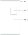
图1是根据一示例性实施例示出的一种终端壳体的结构侧视图,图2是根据一示例性实施例示出的一种终端壳体的结构后视图,图3是根据一示例性实施例示出的一种终端壳体的结构示意图,参见图1、图2和图3,该终端壳体包括后盖101、射频模块102和天线阵列103。FIG. 1 is a structural side view of a terminal housing according to an exemplary embodiment, FIG. 2 is a structural rear view of a terminal housing according to an exemplary embodiment, and FIG. 3 is an exemplary implementation Referring to FIG. 1 , FIG. 2 and FIG. 3 , for a schematic structural diagram of a terminal casing, the terminal casing includes a
其中,该射频模块102可以为WIFI(Wireless Fidelity,无线局域网)模块、蓝牙模块或者用于控制终端收发信号功能的任一模块。并且,射频模块102与天线阵列103导电连接,通过天线阵列103收发信号。The
上述后盖101包括第一区域1011和除第一区域1011以外的第二区域1012,第一区域1011通过绝缘材质与第二区域1012连接。其中,第一区域1011包括多个天线阵元1031,每个天线阵元1031均为导电材质,且任两个相邻的天线阵元1031通过绝缘材质连接,使多个天线阵元1031构成天线阵列103,每个天线阵元1031均作为天线阵列103的辐射体。The above-mentioned
在天线阵列103的工作过程中,射频模块102产生的信号传输至天线阵列103中的多个天线阵元1031,由该多个天线阵元1031发射信号。且发射信号的过程中,多个天线阵元1031的信号合成后形成波束,能够增强辐射场的方向性和信号强度。或者,由多个天线阵元1031进行扫描,接收信号,并将该信号传输至射频模块102中,能够增大扫描范围。During the operation of the
由多个天线阵元1031共同构成天线阵列103,并由该天线阵列103来进行信号收发的方法,使得天线阵列103的信号辐射方向更加集中,在该辐射方向上信号的辐射能量更大,提高了天线阵列103的信号收发能力。The
在一种可能实现方式中,天线阵列103可以为相控阵天线,在工作时,通过改变射频模块102的相位,实现天线阵列103信号的合成与扫描。或者,天线阵列103也可以为其他类型的天线。In a possible implementation manner, the
本公开实施例提供的终端壳体,由于天线阵列所在的第一区域通过绝缘材质与第二区域连接,第一区域包括多个天线阵元,每个天线阵元为导电材质,且任两个天线阵元通过绝缘材质连接,共同构成天线阵列,射频模块与该天线阵列连接,构成了用于接收信号和发射信号的通道。在后盖为金属材质的情况下,后盖上的天线阵列直接进行信号的接收与发送,能够避免金属后盖对天线阵列的信号造成遮挡或屏蔽,保证了天线阵列的性能,而在后盖为非金属材质时,能够使天线阵列的性能得到进一步提升,因此本公开实施例提出的天线阵列可以应用于金属材质或非金属材质的后盖,应用范围更加广泛,提高了灵活性。In the terminal housing provided by the embodiment of the present disclosure, since the first area where the antenna array is located is connected to the second area through an insulating material, the first area includes a plurality of antenna array elements, each antenna array element is made of conductive material, and any two The antenna array elements are connected by insulating materials to form an antenna array together, and the radio frequency module is connected with the antenna array to form a channel for receiving and transmitting signals. When the back cover is made of metal material, the antenna array on the back cover directly receives and transmits signals, which can prevent the metal back cover from blocking or shielding the signals of the antenna array and ensure the performance of the antenna array. When it is made of non-metallic material, the performance of the antenna array can be further improved. Therefore, the antenna array proposed in the embodiment of the present disclosure can be applied to the back cover of metallic material or non-metallic material, and the application range is wider and the flexibility is improved.
图4是根据一示例性实施例示出的一种天线模组的结构示意图,参见图4,该天线模组由上述射频模块102和上述天线阵列103组成,其中射频模块102包括多个射频单元1021,天线阵列103包括多个天线阵元1031,多个射频单元1021的数量与多个天线阵元1031的数量相等,每个射频单元1021与相应的天线阵元1031导电连接。FIG. 4 is a schematic structural diagram of an antenna module according to an exemplary embodiment. Referring to FIG. 4 , the antenna module is composed of the above-mentioned
在天线模组的工作过程中,射频单元1021产生的信号传输至对应天线阵元1031,由该天线阵元1031将该信号发送出去,或者由天线阵元1031接收信号,并将该信号传输至对应的射频单元1021中,实现信号的收发。During the operation of the antenna module, the signal generated by the radio frequency unit 1021 is transmitted to the corresponding
其中,在信号的发射过程中,天线阵元1031接收到对应的射频单元1021传输的信号后,由天线阵元1031向外发射信号,多个天线阵元1031的信号合成后形成波束,该波束朝着后盖101的后侧辐射,不仅可以使信号的辐射方向更加密集,还能增强辐射场的方向性和在辐射方向的信号强度。Among them, in the process of signal transmission, after the
例如,当天线模组要向外发射信号时,多个射频单元1021分别将信号传输至对应的天线阵元1031中,多个天线阵元1031的信号合成后形成波束,该波束沿着合成方向向外辐射,在合成方向上的信号强度得到增强。而当天线模组接收信号时,由多个天线阵元1031分别在各自的扫描角范围内进行扫描,将扫描到的信号接收,并将接收到的信号分别传输至对应的射频单元1021中,实现天线模组的信号接收。For example, when the antenna module wants to transmit signals to the outside, the multiple radio frequency units 1021 transmit the signals to the corresponding
在一种可能实现的方式中,每个射频单元1021与相应的天线阵元1031的内侧通过探针连接,构成一个微带天线,则一共构成多个微带天线,每个微带天线可以单独进行信号的接收与发送。In a possible implementation manner, each radio frequency unit 1021 is connected to the inner side of the corresponding
其中,每个探针与对应的天线阵元1031在某一位置接触,在对应的天线阵元1031中构成一个接触点,则多个射频单元1021分别与相应的天线阵元1031的内侧连接时,会构成多个接触点。由于射频单元1021通过探针为天线阵元1031提供信号,因此探针与天线阵元1031的接触点也被称为馈电点。Wherein, each probe is in contact with the corresponding
在另一种可能实现的方式中,每个射频单元1021与相应的天线阵元1031的内侧焊接,构成一个微带天线,则一共构成多个微带天线,每个微带天线可以单独进行信号的接收与发送。In another possible implementation manner, each radio frequency unit 1021 is welded with the inner side of the corresponding
其中,焊接方式可以在对应的天线阵元1031中构成一个接触点,则多个射频单元1021与相应的天线阵元1031的内侧焊接时,会构成多个接触点。由于射频单元1021通过接触点为天线阵元1031提供信号,因此接触点也被称为馈电点。Wherein, the welding method can form one contact point in the corresponding
在上述两种可能实现的方式中,如图5所示,每个天线阵元1031中馈电点的位置相同。例如,每个天线阵元1031中,馈电点可以位于水平中轴线上靠近左边缘的位置(如图5的示例)、水平中轴线上靠近右边缘的位置或者竖直中轴线上靠近下边缘的位置等。这样可以保证多个天线阵元1031构成的天线阵列103发射的信号在各个方向上辐射均匀,提升了天线阵列103的性能。In the above two possible implementation manners, as shown in FIG. 5 , the positions of the feeding points in each
本公开实施例提供的终端壳体,每个射频模块包括多个射频单元,每个射频单元与对应的天线阵元导电连接,并且馈电点在对应的天线阵元上的位置相同,使得每个由射频单元和天线阵元导电连接后组成的微带天线的性能保持一致,并且在各个方向上辐射均匀,提升了天线阵列的性能。In the terminal housing provided by the embodiment of the present disclosure, each radio frequency module includes a plurality of radio frequency units, each radio frequency unit is conductively connected to the corresponding antenna array element, and the position of the feeding point on the corresponding antenna array element is the same, so that each radio frequency unit is in the same position on the corresponding antenna array element. The performance of each microstrip antenna formed by the conductive connection of the radio frequency unit and the antenna array element is consistent, and the radiation is uniform in all directions, which improves the performance of the antenna array.
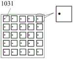
在本发明提供的一示例性实施例中,第一区域1011为方形区域,并且每个天线阵元1031为方形结构。In an exemplary embodiment provided by the present invention, the
在该第一区域1011内有多个天线阵元1031,该多个天线阵元1031在水平方向和竖直方向上等间距排列,构成矩阵结构。其中,每个天线阵元1031的尺寸相同。There are multiple
在一种可能实现的方式中,每个天线阵元1031在水平方向上的边长与在竖直方向上的边长相等,即每个天线阵元1031为正方形。或者,每个天线阵元1031在水平方向上的边长与在竖直方向上的边长不相等,即每个天线阵元1031为矩形。In a possible implementation manner, the side length of each
在另一种可能实现的方式中,第一区域1011在水平方向上的边长与在竖直方向上的边长相等,即第一区域1011为正方形,或者,第一区域1011在水平方向上的边长与在竖直方向上的边长不相等,即第一区域1011为矩形。In another possible implementation manner, the side length of the
在另一种可能实现的方式中,该第一区域1011内的上述矩阵结构中,在水平方向上的天线阵元1031的数量与在竖直方向上的天线阵元1031的数量相等。或者,该第一区域1011内的上述矩阵结构中,在水平方向上的天线阵元1031的数量与在竖直方向上的天线阵元1031的数量不相等。In another possible implementation manner, in the above-mentioned matrix structure in the
例如,如图6所示,每个天线阵元1031为正方形,且天线阵列103中的阵元排列形式为5×5形式,即天线阵列103中,在水平方向上的天线阵元1031的数量是5,在竖直方向上的天线阵元1031的数量也是5。或者,如图7所示,每个天线阵元1031为矩形,且天线阵列103中的阵元排列形式为3×4形式,即天线阵列103中,在水平方向上的天线阵元1031的数量是4,在竖直方向上的天线阵元1031的数量是3。For example, as shown in FIG. 6 , each
采用不同的阵列排列形式,天线阵列的性能也不同。在实际情况中,可以根据收发信号的需求,确定天线阵列103的阵列排列形式。With different array arrangements, the performance of the antenna array is also different. In an actual situation, the array arrangement form of the
本公开实施例提供的终端壳体,多个天线阵元自由组合形成矩阵结构的天线阵列,该天线阵列中任两个天线阵元的尺寸相同,并且由该天线阵列的矩阵结构中,水平方向上的天线阵元的数量与竖直方向上的天线阵元的数量可以相等也可以不相等,因此天线阵列的阵列排列形式自由度较高。在水平方向上的天线阵元的数量与竖直方向上的天线阵元的数量相等的情况下,还能使该天线阵列在水平方向和竖直方向上的性能保持一致,并且在各个方向上的信号辐射均匀,提升了天线阵列的性能。In the terminal housing provided by the embodiment of the present disclosure, a plurality of antenna array elements are freely combined to form an antenna array with a matrix structure, any two antenna elements in the antenna array have the same size, and in the matrix structure of the antenna array, the horizontal direction The number of antenna array elements on the vertical direction may or may not be equal to the number of antenna array elements in the vertical direction, so the array arrangement of the antenna array has a higher degree of freedom. Under the condition that the number of antenna elements in the horizontal direction is equal to the number of antenna elements in the vertical direction, the performance of the antenna array in the horizontal direction and the vertical direction can be kept consistent, and in all directions The signal radiation is uniform, which improves the performance of the antenna array.
并且,由多个射频单元和多个天线阵元组成的微带天线在发射信号时,各个方向上的信号得到叠加,增强了信号的辐射强度,使得天线阵列的性能更加稳定。Moreover, when the microstrip antenna composed of multiple radio frequency units and multiple antenna array elements transmits signals, the signals in all directions are superimposed, which enhances the radiation intensity of the signal and makes the performance of the antenna array more stable.
图8是根据一示例性实施例示出的一种天线阵元中心距离的示意图,参见图8。在一种可能实现的方式中,多个天线阵元1031在水平方向上的任两个相邻天线阵元1031的中心之间的距离d1满足第一预设条件,并且在竖直方向上的任两个相邻天线阵元1031的中心之间的距离d2也满足第一预设条件。FIG. 8 is a schematic diagram showing the center distance of an antenna array element according to an exemplary embodiment, see FIG. 8 . In a possible implementation manner, the distance d1 between the centers of any two adjacent
在另一种可能实现的方式中,多个天线阵元1031中,在水平方向上的任两个相邻天线阵元1031的中心之间的距离d1满足第一预设条件,或者在竖直方向上的任两个相邻天线阵元1031的中心之间的距离d2满足第一预设条件。In another possible implementation manner, among the multiple
在上述两种可能实现的方式中,第一预设条件为:In the above two possible implementation manners, the first preset condition is:
d<=λ/(1+sin(θ))d<=λ/(1+sin(θ))
其中,d为距离d1或d2。λ为天线阵列103的工作波长,θ为天线阵列103的最大扫描角。上述工作波长为天线阵列103正常工作时的波长,该工作波长与天线阵列103正常工作时的频率对应,上述天线阵列103的最大扫描角为该天线阵列103在收发信号时在各个方向上的扫描角度中最大的角度。Among them, d is the distance d1 or d2. λ is the working wavelength of the
上述距离d1或d2过高会使天线阵列103在接收信号或发送信号时产生栅瓣,造成信号能量的损失,并对天线阵列103的工作频率造成影响,使得该天线阵列103无法工作在正确的频段内。而通过设置满足上述第一预设条件的距离d1或d2可以避免产生栅瓣而造成的信号能量损失,保证天线阵列103工作在正确的频段内。The above-mentioned distance d1 or d2 is too high, which will cause the
可选地,天线阵列103可以工作在4G(第四代移动通信技术)或5G(第五代移动通信技术)或通信技术规定的其他工作频段。例如,天线阵列103的工作频段可以为40GHz(吉赫兹)-70GHz,从而构成一种5G天线模组。Optionally, the
图9是根据一示例性实施例示出的一种天线阵元的边长示意图,参见图9。在一种可能实现的方式中,每个天线阵元1031在水平方向上的边长w1满足第二预设条件,并且,每个天线阵元1031在竖直方向上的边长w2也满足第二预设条件。FIG. 9 is a schematic diagram of a side length of an antenna array element according to an exemplary embodiment, see FIG. 9 . In a possible implementation manner, the side length w1 of each
在另一种可能实现的方式中,每个天线阵元1031在水平方向上的边长w1满足第二预设条件,或者,每个天线阵元1031在竖直方向上的边长w2满足第二预设条件。In another possible implementation manner, the side length w1 of each
在上述两种可能实现的方式中,第二预设条件为:In the above two possible implementation manners, the second preset condition is:
90%×λ/2≤w≤110%×λ/290%×λ/2≤w≤110%×λ/2
其中,w为边长w1或w2,λ为天线阵列的工作波长。Among them, w is the side length w1 or w2, and λ is the working wavelength of the antenna array.
上述边长w1或w2过长或过短都会对天线阵列103的工作频率造成影响,使得该天线阵列103无法工作在正确的频段中。而通过设置满足上述第二预设条件的边长w1或w2可以保证天线阵列103工作在正确的频段内,并使得天线阵列的性能更加稳定。If the side length w1 or w2 is too long or too short, it will affect the working frequency of the
在本发明提供的一示例性实施例中,后盖101为金属材质,后盖101上的绝缘材质采用注塑工艺在后盖101上形成。In an exemplary embodiment provided by the present invention, the
例如,后盖101为金属材质,在后盖101上通过注塑工艺形成注塑条,将后盖101分隔为第一区域1011和第二区域1012。其中,上述注塑条为绝缘材质,可以将第一区域1011和第二区域1012绝缘断开。并且,在第一区域1011内通过注塑工艺形成多个注塑条,将第一区域1011分隔成多个天线阵元1031,得到由多个天线阵元1031共同组成的天线阵列103。其中,上述注塑条为绝缘材质,可以将多个天线阵元1031绝缘断开。For example, the
可选地,上述绝缘材质可以为低密度聚乙烯、高密度聚乙烯、聚丙烯或其他绝缘材质。Optionally, the above-mentioned insulating material may be low-density polyethylene, high-density polyethylene, polypropylene or other insulating materials.
本发明实施例提供的终端壳体,通过采用金属材质的后盖,并在后盖上采用注塑工艺形成绝缘材质,从而构成天线阵列,能够避免天线阵列的信号收发受到金属后盖的遮盖和屏蔽,保证天线阵列的性能,并使得应用范围更加广泛。In the terminal housing provided by the embodiment of the present invention, an antenna array is formed by using a metal back cover and an insulating material is formed on the back cover by an injection molding process, which can prevent the signal transmission and reception of the antenna array from being covered and shielded by the metal back cover , to ensure the performance of the antenna array and make the application range wider.
在本发明提供的另一示例性实施例中,后盖101为绝缘材质,在该绝缘材质的后盖101上设置有多个通孔,每个天线阵元1031分别位于后盖101上的一个通孔中,并采用注塑工艺与所处的通孔内侧连接。其中,上述多个通孔的数量与多个天线阵元1031的数量相同。In another exemplary embodiment provided by the present invention, the
例如,后盖101的材质为非金属材质,后盖101上设置有多个通孔,将每个用于形成天线阵元1031的导电材质放置于对应的通孔中,并采用注塑工艺在通孔内侧形成注塑条,使每个导电材质通过注塑条与所处的通孔内侧连接,形成天线阵元1031,则多个通孔中的天线阵元1031共同构成天线阵列103。其中,该非金属材质可以为塑料材质、玻璃材质或其他材质。For example, the material of the
本发明实施例提供的终端壳体,在采用非金属材质的后盖的情况下,在后盖的通孔内采用注塑工艺形成天线阵元,使后盖上的多个天线阵元构成天线阵列,可以直接与射频单元导电连接后进行信号的发射与接收,避免了天线阵列的信号收发受到后盖的遮盖,可以有效降低非金属后盖带来的信号能量损耗,进一步提升天线阵列的性能。In the terminal housing provided by the embodiment of the present invention, in the case of using a back cover of non-metallic material, an antenna array element is formed in the through hole of the back cover by an injection molding process, so that a plurality of antenna array elements on the back cover form an antenna array , can be directly conductively connected with the radio frequency unit to transmit and receive signals, avoid the signal transmission and reception of the antenna array being covered by the back cover, can effectively reduce the signal energy loss caused by the non-metal back cover, and further improve the performance of the antenna array.
综上所述,本公开实施例提供的终端壳体,提出了一种天线阵列的设计方案,在终端壳体的后盖上开设第一区域,在第一区域中设置多个天线阵元,该多个天线阵元通过绝缘物质连接共同构成天线阵列,该天线阵列通过绝缘物质与后盖上除第一区域以外的第二区域连接,并且将射频模块包含的多个射频单元中每个射频单元与对应的天线阵元导电连接,可以传输用于发射或接收的信号,该天线阵列位于终端壳体上,没有被后盖覆盖,可以直接进行信号的接收与发送,因此可以避免由于后盖采用金属材质而对天线阵列的信号进行遮挡和屏蔽,保证了天线阵列的性能。并且在后盖采用非金属材质的情况下,可以有效降低非金属后盖带来的信号能量损耗,进一步提高天线阵列的信号收发性能。因此,本公开实施例提出的天线阵列可以应用于金属材质或非金属材质的后盖,摆脱了后盖只能采用非金属材质的限制,应用范围更加广泛,提高了灵活性。To sum up, the terminal housing provided by the embodiments of the present disclosure proposes a design scheme of an antenna array, in which a first area is opened on the back cover of the terminal housing, and a plurality of antenna array elements are arranged in the first area. The plurality of antenna array elements are connected by an insulating material to form an antenna array, the antenna array is connected to the second area on the back cover except the first area by the insulating material, and each radio frequency unit of the plurality of radio frequency units included in the radio frequency module is connected to each other. The unit is conductively connected to the corresponding antenna array element, which can transmit signals for transmission or reception. The antenna array is located on the terminal housing and is not covered by the back cover. Signal reception and transmission can be performed directly, so it can be avoided due to the back cover. The metal material is used to block and shield the signal of the antenna array to ensure the performance of the antenna array. In addition, when the back cover is made of a non-metallic material, the signal energy loss caused by the non-metallic back cover can be effectively reduced, and the signal transmission and reception performance of the antenna array can be further improved. Therefore, the antenna array proposed in the embodiments of the present disclosure can be applied to a back cover made of metal or non-metal material, which gets rid of the limitation that the back cover can only be made of non-metal material, has wider application range, and improves flexibility.
本公开实施例还提供了一种终端,该终端包括上述实施例中涉及的终端壳体,包含该终端壳体的全部结构和功能。当然,该终端还包括显示屏幕、终端前壳、主板以及终端内其他的电子元器件,如扬声器和麦克风等。由上述终端壳体内所形成的天线单元与终端内的其他电子元件配合工作,以实现终端的通信功能,本公开对其具体组成不做限定。An embodiment of the present disclosure further provides a terminal, where the terminal includes the terminal casing involved in the foregoing embodiments, and includes all the structures and functions of the terminal casing. Of course, the terminal also includes a display screen, a front case of the terminal, a main board, and other electronic components in the terminal, such as a speaker and a microphone. The antenna unit formed in the above-mentioned terminal housing cooperates with other electronic components in the terminal to realize the communication function of the terminal, and the specific composition thereof is not limited in the present disclosure.
在该终端中,天线阵列可以配置于不同的位置,且由于多个天线阵元需要进行信号合成,因此该多个天线阵元应进行规则摆放,根据天线阵列在终端中的位置不同,可以分为AoB(Antenna on Board,即天线阵列位于系统主板上)、AiP(Antenna in Package,即天线阵列位于芯片的封装内),以及AiM(Antenna in Module,即天线阵列与RFIC形成一模组)等多种类型。In the terminal, the antenna array can be configured in different positions, and since multiple antenna elements need to perform signal synthesis, the multiple antenna elements should be placed regularly. According to the different positions of the antenna array in the terminal, the It is divided into AoB (Antenna on Board, that is, the antenna array is located on the system motherboard), AiP (Antenna in Package, that is, the antenna array is located in the package of the chip), and AiM (Antenna in Module, that is, the antenna array and RFIC form a module) and many other types.
并且,天线阵列和射频模块整合在一个模组内,置于终端的主板上,天线阵列的阵面与显示屏幕平行。In addition, the antenna array and the radio frequency module are integrated in a module, which is placed on the main board of the terminal, and the front of the antenna array is parallel to the display screen.
本领域技术人员在考虑说明书及实践这里公开的发明后,将容易想到本公开的其它实施方案。本申请旨在涵盖本公开的任何变型、用途或者适应性变化,这些变型、用途或者适应性变化遵循本公开的一般性原理并包括本公开未公开的本技术领域中的公知常识或惯用技术手段。说明书和实施例仅被视为示例性的,本公开的真正范围和精神由下面的权利要求指出。Other embodiments of the present disclosure will readily occur to those skilled in the art upon consideration of the specification and practice of the invention disclosed herein. This application is intended to cover any variations, uses, or adaptations of the present disclosure that follow the general principles of the present disclosure and include common knowledge or techniques in the technical field not disclosed by the present disclosure . The specification and examples are to be regarded as exemplary only, with the true scope and spirit of the disclosure being indicated by the following claims.
应当理解的是,本公开并不局限于上面已经描述并在附图中示出的精确结构,并且可以在不脱离其范围进行各种修改和改变。本公开的范围仅由所附的权利要求来限制。It is to be understood that the present disclosure is not limited to the precise structures described above and illustrated in the accompanying drawings, and that various modifications and changes may be made without departing from the scope thereof. The scope of the present disclosure is limited only by the appended claims.
Claims (8)
Priority Applications (3)
| Application Number | Priority Date | Filing Date | Title |
|---|---|---|---|
| CN201811140338.1ACN109193119B (en) | 2018-09-28 | 2018-09-28 | Terminal housings and terminals |
| US16/232,264US11158931B2 (en) | 2018-09-28 | 2018-12-26 | Terminal housing and terminal |
| EP19193923.0AEP3629416B1 (en) | 2018-09-28 | 2019-08-27 | Terminal housing and terminal |
Applications Claiming Priority (1)
| Application Number | Priority Date | Filing Date | Title |
|---|---|---|---|
| CN201811140338.1ACN109193119B (en) | 2018-09-28 | 2018-09-28 | Terminal housings and terminals |
Publications (2)
| Publication Number | Publication Date |
|---|---|
| CN109193119A CN109193119A (en) | 2019-01-11 |
| CN109193119Btrue CN109193119B (en) | 2021-08-17 |
Family
ID=64907169
Family Applications (1)
| Application Number | Title | Priority Date | Filing Date |
|---|---|---|---|
| CN201811140338.1AActiveCN109193119B (en) | 2018-09-28 | 2018-09-28 | Terminal housings and terminals |
Country Status (3)
| Country | Link |
|---|---|
| US (1) | US11158931B2 (en) |
| EP (1) | EP3629416B1 (en) |
| CN (1) | CN109193119B (en) |
Families Citing this family (4)
| Publication number | Priority date | Publication date | Assignee | Title |
|---|---|---|---|---|
| CN109659670B (en)* | 2019-02-25 | 2024-05-10 | 昆山联滔电子有限公司 | Antenna assembly |
| WO2021060566A1 (en)* | 2019-09-26 | 2021-04-01 | キヤノン株式会社 | Image forming device |
| CN116014457A (en) | 2021-10-21 | 2023-04-25 | 深圳富泰宏精密工业有限公司 | Antenna system and wireless communication device with same |
| TWI832108B (en)* | 2021-10-21 | 2024-02-11 | 群邁通訊股份有限公司 | Wireless communication device |
Citations (4)
| Publication number | Priority date | Publication date | Assignee | Title |
|---|---|---|---|---|
| WO2013167075A2 (en)* | 2013-01-28 | 2013-11-14 | 中兴通讯股份有限公司 | Antenna system |
| CN206962002U (en)* | 2017-06-22 | 2018-02-02 | 维沃移动通信有限公司 | A kind of terminal |
| CN108281802A (en)* | 2017-12-13 | 2018-07-13 | 瑞声科技(新加坡)有限公司 | Phased array antenna system and mobile terminal |
| CN108448229A (en)* | 2018-01-25 | 2018-08-24 | 瑞声科技(南京)有限公司 | Antenna system and communicating terminal |
Family Cites Families (16)
| Publication number | Priority date | Publication date | Assignee | Title |
|---|---|---|---|---|
| SE511907C2 (en) | 1997-10-01 | 1999-12-13 | Ericsson Telefon Ab L M | Integrated communication device |
| US8872719B2 (en)* | 2009-11-09 | 2014-10-28 | Linear Signal, Inc. | Apparatus, system, and method for integrated modular phased array tile configuration |
| KR101916241B1 (en)* | 2012-03-12 | 2018-11-07 | 삼성전자주식회사 | Antenna apparatus for portable terminal |
| US9293816B2 (en) | 2012-07-06 | 2016-03-22 | Apple Inc. | Electronic device plate antenna |
| KR20140112325A (en) | 2013-03-13 | 2014-09-23 | 삼성전자주식회사 | Electronic device and method for forming thereof |
| US9209513B2 (en)* | 2013-06-07 | 2015-12-08 | Apple Inc. | Antenna window and antenna pattern for electronic devices and methods of manufacturing the same |
| US10205489B2 (en)* | 2013-10-07 | 2019-02-12 | Amotech Co., Ltd. | Rear cover and portable terminal having same |
| US9547070B2 (en) | 2013-12-26 | 2017-01-17 | International Business Machines Corporation | Radar integration with handheld electronic devices |
| US9059505B1 (en) | 2013-12-31 | 2015-06-16 | Google Technology Holdings LLC | Systems and methods for a reconfigurable antenna using design elements on an electronic device housing |
| US9985345B2 (en)* | 2015-04-10 | 2018-05-29 | Apple Inc. | Methods for electrically isolating areas of a metal body |
| US9667290B2 (en)* | 2015-04-17 | 2017-05-30 | Apple Inc. | Electronic device with millimeter wave antennas |
| US10361476B2 (en)* | 2015-05-26 | 2019-07-23 | Qualcomm Incorporated | Antenna structures for wireless communications |
| CN104900989B (en)* | 2015-06-09 | 2017-12-29 | 联想(北京)有限公司 | Electronic equipment and containment vessel |
| US10693213B2 (en) | 2016-06-30 | 2020-06-23 | Hon Hai Precision Industry Co., Ltd. | Antenna module and a wireless device having the same |
| CN108376828B (en) | 2018-01-25 | 2021-01-12 | 瑞声科技(南京)有限公司 | Antenna system and mobile terminal |
| KR102511096B1 (en)* | 2018-04-11 | 2023-03-16 | 삼성전자 주식회사 | An electronic device including a cover combined with an antenna module |
- 2018
- 2018-09-28CNCN201811140338.1Apatent/CN109193119B/enactiveActive
- 2018-12-26USUS16/232,264patent/US11158931B2/enactiveActive
- 2019
- 2019-08-27EPEP19193923.0Apatent/EP3629416B1/enactiveActive
Patent Citations (4)
| Publication number | Priority date | Publication date | Assignee | Title |
|---|---|---|---|---|
| WO2013167075A2 (en)* | 2013-01-28 | 2013-11-14 | 中兴通讯股份有限公司 | Antenna system |
| CN206962002U (en)* | 2017-06-22 | 2018-02-02 | 维沃移动通信有限公司 | A kind of terminal |
| CN108281802A (en)* | 2017-12-13 | 2018-07-13 | 瑞声科技(新加坡)有限公司 | Phased array antenna system and mobile terminal |
| CN108448229A (en)* | 2018-01-25 | 2018-08-24 | 瑞声科技(南京)有限公司 | Antenna system and communicating terminal |
Also Published As
| Publication number | Publication date |
|---|---|
| CN109193119A (en) | 2019-01-11 |
| US11158931B2 (en) | 2021-10-26 |
| EP3629416B1 (en) | 2024-02-21 |
| EP3629416A1 (en) | 2020-04-01 |
| US20200106173A1 (en) | 2020-04-02 |
Similar Documents
| Publication | Publication Date | Title |
|---|---|---|
| JP7287739B2 (en) | communication device | |
| US20220255240A1 (en) | Antenna module and electronic device | |
| CN109193119B (en) | Terminal housings and terminals | |
| US20220085493A1 (en) | Housing assembly, antenna device, and electronic device | |
| US11355853B2 (en) | Antenna structure and wireless communication device using the same | |
| CN104966899B (en) | A kind of omnidirectional antenna and omni-directional antenna arrays | |
| CN111864362A (en) | Antenna modules and electronic equipment | |
| TWI487191B (en) | Antenna system | |
| US12224254B2 (en) | Millimeter-wave antenna chip and terminal device | |
| CN116420279A (en) | Multi-frequency antenna and communication equipment | |
| CN111463582A (en) | Antenna modules and terminals | |
| WO2020083075A1 (en) | Terminal | |
| US20070126640A1 (en) | Planar antenna structure | |
| CN111864343A (en) | Electronic equipment | |
| CN112153833A (en) | Housing assembly, antenna device and electronic equipment | |
| CN215732189U (en) | Display device and antenna assembly thereof | |
| CN113708056B (en) | Antenna device and radio communication apparatus | |
| CN210379412U (en) | Antenna, antenna assembly and electronic equipment | |
| CN112310652B (en) | Electronic equipment | |
| WO2022228188A1 (en) | Antenna array, antenna module, and electronic device | |
| CN113964518A (en) | Antenna device and electronic equipment | |
| CN113571882B (en) | Communication equipment | |
| CN111224217A (en) | Terminal and communication method | |
| WO2024114283A1 (en) | Antenna structure and electronic device | |
| CN116799483A (en) | Antennas and electronic equipment |
Legal Events
| Date | Code | Title | Description |
|---|---|---|---|
| PB01 | Publication | ||
| PB01 | Publication | ||
| SE01 | Entry into force of request for substantive examination | ||
| SE01 | Entry into force of request for substantive examination | ||
| GR01 | Patent grant | ||
| GR01 | Patent grant |