CN109188366B - Adaptive Beamforming Method for Wideband Transmission Based on Subband Maximum SNR Criterion - Google Patents
Adaptive Beamforming Method for Wideband Transmission Based on Subband Maximum SNR CriterionDownload PDFInfo
- Publication number
- CN109188366B CN109188366BCN201810895372.3ACN201810895372ACN109188366BCN 109188366 BCN109188366 BCN 109188366BCN 201810895372 ACN201810895372 ACN 201810895372ACN 109188366 BCN109188366 BCN 109188366B
- Authority
- CN
- China
- Prior art keywords
- signal
- subband
- sub
- frequency
- broadband
- Prior art date
- Legal status (The legal status is an assumption and is not a legal conclusion. Google has not performed a legal analysis and makes no representation as to the accuracy of the status listed.)
- Active
Links
- 238000000034methodMethods0.000titleclaimsabstractdescription22
- 230000003044adaptive effectEffects0.000titleclaimsdescription18
- 230000005540biological transmissionEffects0.000titleclaimsdescription16
- 238000004458analytical methodMethods0.000claimsabstractdescription31
- 239000013598vectorSubstances0.000claimsabstractdescription25
- 230000004044responseEffects0.000claimsdescription25
- 230000015572biosynthetic processEffects0.000claimsdescription18
- 238000003786synthesis reactionMethods0.000claimsdescription18
- 238000012545processingMethods0.000claimsdescription17
- 239000011159matrix materialSubstances0.000claimsdescription14
- 238000005070samplingMethods0.000claimsdescription7
- 238000013519translationMethods0.000claimsdescription2
- 230000009286beneficial effectEffects0.000abstractdescription2
- 238000004422calculation algorithmMethods0.000description40
- 238000010586diagramMethods0.000description8
- 238000004088simulationMethods0.000description5
- 230000008859changeEffects0.000description4
- 238000004364calculation methodMethods0.000description3
- 239000000654additiveSubstances0.000description2
- 230000000996additive effectEffects0.000description2
- 238000000354decomposition reactionMethods0.000description2
- 230000000694effectsEffects0.000description2
- 230000002452interceptive effectEffects0.000description2
- 230000008569processEffects0.000description2
- 230000001629suppressionEffects0.000description2
- 238000007476Maximum LikelihoodMethods0.000description1
- 238000003491arrayMethods0.000description1
- 230000008901benefitEffects0.000description1
- 238000005094computer simulationMethods0.000description1
- 238000013461designMethods0.000description1
- 238000001514detection methodMethods0.000description1
- 238000005516engineering processMethods0.000description1
- 230000007613environmental effectEffects0.000description1
- 230000010363phase shiftEffects0.000description1
- 230000005855radiationEffects0.000description1
- 238000011160researchMethods0.000description1
- 230000008054signal transmissionEffects0.000description1
- 230000002123temporal effectEffects0.000description1
- 230000009466transformationEffects0.000description1
- 230000007704transitionEffects0.000description1
Images


Classifications
- G—PHYSICS
- G01—MEASURING; TESTING
- G01S—RADIO DIRECTION-FINDING; RADIO NAVIGATION; DETERMINING DISTANCE OR VELOCITY BY USE OF RADIO WAVES; LOCATING OR PRESENCE-DETECTING BY USE OF THE REFLECTION OR RERADIATION OF RADIO WAVES; ANALOGOUS ARRANGEMENTS USING OTHER WAVES
- G01S7/00—Details of systems according to groups G01S13/00, G01S15/00, G01S17/00
- G01S7/02—Details of systems according to groups G01S13/00, G01S15/00, G01S17/00 of systems according to group G01S13/00
Landscapes
- Engineering & Computer Science (AREA)
- Computer Networks & Wireless Communication (AREA)
- Physics & Mathematics (AREA)
- General Physics & Mathematics (AREA)
- Radar, Positioning & Navigation (AREA)
- Remote Sensing (AREA)
- Variable-Direction Aerials And Aerial Arrays (AREA)
Abstract
Description
Translated fromChinese技术领域technical field
本发明属于阵列信号处理领域,具体涉及一种基于子带最大信噪比准则的宽带发射自适应波束形成方法。The invention belongs to the field of array signal processing, and in particular relates to a wideband transmission adaptive beamforming method based on the subband maximum signal-to-noise ratio criterion.
背景技术Background technique
现代雷达系统中部署的自适应阵列往往将用于衰减干扰信号的零陷置于接收端,诸如敌对干扰,无意电磁干扰或环境杂波等,这种方案的天线通常在孔径上以均匀的幅度加权进行发送,以最大化主波束增益。这种在雷达接收端信号处理技术已日趋完善,通过优化雷达接收信号处理算法提升探测性能越来越困难,因此,最近越来越多的研究机构已经开发了用于在雷达的发射端创建零陷的技术,其好处是天线可以对干扰信号施加显著的双向损耗。迄今为止,所开发的大多数发射置零算法都适用于窄带应用,并假设无限的相位和幅度精度。Adaptive arrays deployed in modern radar systems often place nulls at the receiving end to attenuate interfering signals, such as hostile jamming, unintentional electromagnetic interference, or environmental clutter. The antennas of this scheme usually have a uniform amplitude on the aperture The transmission is weighted to maximize the main beam gain. This kind of signal processing technology at the radar receiving end has been perfected day by day, and it is becoming more and more difficult to improve the detection performance by optimizing the radar receiving signal processing algorithm. Therefore, more and more research institutions have recently developed methods for creating zero The benefit of this technique is that the antenna can impose significant two-way losses on the interfering signal. Most transmit nulling algorithms developed to date are suitable for narrowband applications and assume infinite phase and amplitude accuracy.
一般情况下,每个阵元所应用的加权值只计算在阵列信号的中心频率上,对应于阵元之间的半波长间距。此外,每个阵元后面的移相器只对信号中心频率进行校正。因此,每个阵元发射的宽带信号的实际相移会随实际频率而偏移,从而导致在整个信号带宽上,发射信号的零陷会偏离指向方向。In general, the weighting applied to each array element is only calculated at the center frequency of the array signal, corresponding to the half-wavelength spacing between the array elements. In addition, the phase shifters behind each array element only correct for the center frequency of the signal. Therefore, the actual phase shift of the broadband signal transmitted by each array element will shift with the actual frequency, so that the null of the transmitted signal will deviate from the pointing direction across the entire signal bandwidth.
为了解决上述问题,Peter G.Vouras提出了一种宽带阵列鲁棒传输置零(RobustTransmit Nulling,RTN)波束形成算法,该算法为了使发射信号信噪比(SINR)最大,推导出了关于频率积分的SINR函数,并通过共轭迭代算法对SINR函数进行求解,从而得出最优抽头延迟线系数。由于该算法在共轭迭代初值设置存在一些问题且迭代步长计算复杂,为了得出最优解,往往需要多次共轭迭代,使计算量大幅度增加,增加了系统的负荷,不利于工程实施。In order to solve the above problems, Peter G.Vouras proposed a broadband array Robust Transmit Nulling (RTN) beamforming algorithm. In order to maximize the signal-to-noise ratio (SINR) of the transmitted signal, the algorithm deduces the frequency integral The SINR function, and through the conjugate iterative algorithm to solve the SINR function, so as to obtain the optimal tapped delay line coefficient. Since the algorithm has some problems in the initial value setting of the conjugate iteration and the calculation of the iteration step is complicated, in order to obtain the optimal solution, multiple conjugate iterations are often required, which greatly increases the amount of calculation and increases the load of the system, which is not conducive to Engineering implementation.
发明内容Contents of the invention
本发明提供了一种基于子带最大信噪比准则的宽带发射自适应波束形成方法,发射波束能够在期望位置形成深度很深且方向不随频率变化的零陷,计算量较小,利于工程实现。The present invention provides a wideband transmission adaptive beamforming method based on the subband maximum signal-to-noise ratio criterion. The transmission beam can form a deep null at the desired position and the direction does not change with frequency, and the calculation amount is small, which is beneficial to engineering realization. .
为了解决上述技术问题,采用以下技术方案:In order to solve the above technical problems, the following technical solutions are adopted:
基于子带最大信噪比准则的宽带发射自适应波束形成方法,包括如下步骤:A wideband transmission adaptive beamforming method based on the subband maximum signal-to-noise ratio criterion, comprising the following steps:
步骤一、设计宽带发射天线阵列,计算宽带阵列的输出信号;
步骤二、设计子带滤波器组;Step 2, designing a subband filter bank;
步骤三、利用子带滤波器组中的分析滤波器组完成宽带信号的子带划分;Step 3, utilizing the analysis filter bank in the subband filter bank to complete the subband division of the wideband signal;
步骤四、基于子带最大信噪比准则计算各个子带自适应波束形成权矢量;Step 4. Calculate the adaptive beamforming weight vector of each subband based on the maximum SNR criterion of the subband;
步骤五、利用子带滤波器组中的综合滤波器组将经过处理的宽带信号进行重构。Step 5: Reconstruct the processed broadband signal by using the integrated filter bank in the subband filter bank.
进一步的,所述的宽带发射天线阵列是阵元个数为M的均匀直线阵列,每个阵元后面是一个等效于离散有限冲激响应滤波器的抽头延迟线(Tapped Delay Line,TDL),TDL系数为J,宽带阵列的原始输出信号x(n)的最低频率为fL,最高频率为fH,n=0,±1,±2,…。Further, the broadband transmitting antenna array is a uniform linear array with the number of array elements being M, and behind each array element is a tapped delay line (Tapped Delay Line, TDL) equivalent to a discrete finite impulse response filter , the TDL coefficient is J, the lowest frequency of the original output signal x(n) of the broadband array is fL , the highest frequency is fH , n=0,±1,±2,….
TDL阵列的响应满足以下公式:The response of the TDL array satisfies the following formula:

其中,j为虚数单位,θ0为阵列信号发射方向,ω为数字频率,wm[k]为第m个阵元的第k个抽头的加权值,m=0,1,…,M-1,k=0,1,…,J-1,Ts为相邻两个抽头的采样时间间隔,φ为相邻两个阵元传输信号的相位差,且φ满足公式:Among them, j is the imaginary number unit, θ0 is the transmitting direction of the array signal, ω is the digital frequency, wm [k] is the weighted value of the kth tap of the mth array element, m=0,1,...,M- 1, k=0,1,...,J-1, Ts is the sampling time interval of two adjacent taps, φ is the phase difference of the transmission signals of two adjacent array elements, and φ satisfies the formula:

其中,d为阵元间距,f为瞬时频率,c为光速。Among them, d is the distance between array elements, f is the instantaneous frequency, and c is the speed of light.
为了防止空间混频,设置d=c/(2fH),为了避免瞬时混频,设置Ts=1/(2fH)。To prevent spatial mixing, set d=c/(2fH ), and to avoid temporal mixing, set Ts =1/(2fH ).
第m个阵元的输出信号为:The output signal of the mth array element is:

其中,xm(n)为第m个阵元的输出信号,x(n-k)表示输入离散信号x(n)向左平移k个单位。Among them, xm (n) is the output signal of the mth array element, and x(nk) means that the input discrete signal x(n) is shifted to the left by k units.
进一步的,所述的子带滤波器组选用离散傅里叶变换滤波器组(DiscreteFourier Transform Filter Bank,DFTFB),子带滤波器组通常包括两组滤波器组,其中一组是分析滤波器组,用于宽带信号的分解,分解之后的各路子带可单独进行所需的信号处理;另外一组是综合滤波器组,用于宽带信号的重构,重构之后得到系统处理后的输出信号。Further, the sub-band filter bank selects discrete Fourier transform filter bank (DiscreteFourier Transform Filter Bank, DFTFB), and the sub-band filter bank usually includes two groups of filter banks, one of which is an analysis filter bank , used for the decomposition of broadband signals, each sub-band after decomposition can perform the required signal processing independently; the other group is a comprehensive filter bank, used for reconstruction of broadband signals, after reconstruction, the output signal after system processing can be obtained .
进一步的,每个阵元后面有Q个子带处理通道,每个子带处理通道中有一个分析滤波器和一个综合滤波器。每个子带通道中的分析滤波器是由一个长度为P的低通原型滤波器H0(z)平移获得,在采样频率为fs时,长度为P的滤波器Hq(z)可将带宽为B的宽带信号过滤成带宽为fs/P的子带信号,因此滤波器的长度P=fs/(B/M)。第q个子带分析滤波器冲击响应满足以下公式:Further, there are Q subband processing channels behind each array element, and each subband processing channel has an analysis filter and a synthesis filter. The analysis filter in each subband channel is obtained by translation of a low-pass prototype filter H0 (z) of length P. When the sampling frequency is fs , the filter Hq (z) of length P can convert A broadband signal with a bandwidth of B is filtered into a subband signal with a bandwidth of fs /P, so the length of the filter is P=fs /(B/M). The qth subband analysis filter impulse response satisfies the following formula:
Hq(z)=H0(zWq+i) (4)Hq (z)=H0 (zWq+i ) (4)
H0(z)=1+z-1+…+z-(P-1) (5)H0 (z)=1+z-1 +...+z-(P-1) (5)
其中,Hq(z)表示第q个通道分析滤波器冲击响应的z变换,q=1,...,Q且复变量z=ejω,W=e-j2π/P,q+i表示第q个子带分析滤波器相对于低通滤波器H0(z)的频率偏移,且i=fL/(B/M)-0.5。Among them, Hq (z) represents the z transformation of the impulse response of the qth channel analysis filter, q=1,...,Q and the complex variable z=ejω , W=e-j2π/P , q+i represents The frequency offset of the qth sub-band analysis filter relative to the low-pass filter H0 (z), and i=fL /(B/M)-0.5.
第q个子带综合滤波器冲击响应满足以下公式:The qth subband synthesis filter impulse response satisfies the following formula:
Fq(z)=W-(q+i)F0(zWq+i) (6)Fq (z)=W-(q+i) F0 (zWq+i ) (6)
F0(z)=1+z-1+…+z-(P-1) (7)F0 (z)=1+z-1 +...+z-(P-1) (7)
其中,Fq(z)表示第q个通道综合滤波器冲击响应的z变换。Among them, Fq (z) represents the z-transform of the impulse response of the synthesis filter of the qth channel.
由上式可以得出,每个综合滤波器和相应的分析滤波器有相同的幅值响应,宽带信号如果只是经过子带划分和重构不会改变原始信号的频率信息,是经过子带划分和重构得到的输出信号满足公式:It can be concluded from the above formula that each synthesis filter and the corresponding analysis filter have the same amplitude response. If the broadband signal is only divided into subbands and reconstructed, the frequency information of the original signal will not be changed. And the output signal obtained by reconstruction satisfies the formula:
y(n)=Qx(n-Q+1) (8)y(n)=Qx(n-Q+1) (8)
其中,y(n)是经过子带划分和重构的输出信号,x(n-Q+1)表示离散信号x(n)向右平移Q-1个单位。Wherein, y(n) is the output signal after sub-band division and reconstruction, and x(n-Q+1) indicates that the discrete signal x(n) is shifted to the right by Q-1 unit.
进一步的,当宽带信号发射方向为θ0时,信号的阵列导引矢量满足公式:Furthermore, when the broadband signal transmission direction is θ0 , the array steering vector of the signal satisfies the formula:
v(θ0,f)=[1,exp(j2πfdsinθ0/c),…,exp(j2πfd(M-1)sinθ0/c)]T (9)v(θ0 ,f)=[1,exp(j2πfdsinθ0 /c),…,exp(j2πfd(M-1)sinθ0 /c)]T (9)
其中,[·]T为转置运算符,v(θ0,f)表示发射方向为为θ0、频率为f的信号阵列导引矢量。Among them, [·]T is the transpose operator, and v(θ0 , f) represents the steering vector of the signal array with the transmitting direction θ0 and the frequency f.
分析滤波器进行子带划分后,TDL的抽头采样频率降为原来的1/Q,其子带TDL延迟链向量满足公式:After the analysis filter is divided into subbands, the tap sampling frequency of TDL is reduced to the original 1/Q, and the subband TDL delay chain vector satisfies the formula:

与信号频率相关的空时导引矢量满足公式:The space-time steering vector related to the signal frequency satisfies the formula:

式中,
进一步的,设分析滤波器将宽带信号带宽均匀的划分为K个频点,则有{f1,f2,...,fK}∈[fL,fH],信号方差矩阵和干扰噪声协方差矩阵满足以下公式:Further, assuming that the analysis filter divides the broadband signal bandwidth evenly into K frequency points, then there are {f1 ,f2 ,...,fK }∈[fL ,fH ], signal variance matrix and interference The noise covariance matrix satisfies the following formula:


其中,[·]H为转置共轭运算符,Rst-q是第q个子带信号的信号方差矩阵,Nst-q是第q个子带信号的干扰噪声协方差矩阵,K是频点总数,Vst-q(θ0,fl)表示频率为fl时的空时导引矢量,Hq(fl)表示频率为fl时第q个子带分析滤波器的频率响应,Fq(fl)表示频率为fl时第q个子带综合滤波器的频率响应,β是干扰信号的功率,σ2是零均值加性白噪声高斯过程的功率,I为单位矩阵,θ0是主瓣方向,θ1是期望形成零陷的方向,fl∈{f1,f2,...,fK}且l=1,2,...,K。Among them, [ ]H is the transpose conjugate operator, Rst-q is the signal variance matrix of the qth sub-band signal, Nst-q is the interference noise covariance matrix of the qth sub-band signal, K is the frequency point The total, Vst-q (θ0 ,fl ) represents the space-time steering vector at frequency fl , Hq (fl ) represents the frequency response of the qth subband analysis filter at frequency fl , Fq (fl ) represents the frequency response of the qth sub-band synthesis filter when the frequency is fl , β is the power of the interference signal, σ2 is the power of the zero-mean additive white noise Gaussian process, I is the identity matrix, θ0 is the direction of the main lobe, θ1 is the direction expected to form a null, fl ∈{f1 ,f2 ,...,fK } and l=1,2,...,K.
进一步的,第q个子带信号的信噪比SINRq满足公式:Further, the signal-to-noise ratio SINRq of the qth sub-band signal satisfies the formula:

其中,Wq是第q个子带信号的NJ×1维TDL权矢量,当SINRq最大时,得到权矢量最优解:Among them, Wq is the NJ×1-dimensional TDL weight vector of the qth sub-band signal. When the SINRq is the largest, the optimal solution of the weight vector is obtained:

其中,Wopt-q是子带最优TDL权矢量,λmax是
进一步的,根据综合滤波器组的重构,经过发射自适应波束形成,第m个阵元输出的信号的频域表达式为:Further, according to the reconstruction of the integrated filter bank, after transmitting adaptive beamforming, the frequency domain expression of the signal output by the mth array element is:

其中,Ym(ejω)表示第m个阵元输出的信号的频域,wqm[k]表示第m个阵元第q个子带的第k个抽头加权值,X(ejω)表示原始宽带信号的频域,Hq(ejω)表示第q个子带的分析滤波器的频率响应,Fq(ejω)表示第q个子带的综合滤波器的频率响应。Among them, Ym (ejω ) represents the frequency domain of the signal output by the mth array element, wqm [k] represents the kth tap weight value of the qth subband of the mth array element, and X(ejω ) represents In the frequency domain of the original broadband signal, Hq (ejω ) represents the frequency response of the analysis filter for the qth subband, and Fq (ejω ) represents the frequency response of the synthesis filter for the qth subband.
进一步的,综合滤波器组重构后的宽带输出信号发射波束天线方向图为:Further, the broadband output signal transmit beam antenna pattern after reconstruction of the integrated filter bank is:

其中,P(θ,f)表示宽带信号发射波束天线方向图,vst(θ,f)表示宽带信号发射方向为θ、频率为f时的空时导引矢量,Hq(f)表示频率为f时第q个子带分析滤波器的频率响应,Fq(f)表示频率为f时第q个子带综合滤波器的频率响应。Among them, P(θ,f) represents the broadband signal transmitting beam antenna pattern, vst (θ,f) represents the space-time steering vector when the broadband signal transmitting direction is θ and the frequency is f, Hq (f) represents the frequency When f is the frequency response of the qth subband analysis filter, Fq (f) represents the frequency response of the qth subband synthesis filter when the frequency is f.
通过上述技术手段,可以获得以下技术效果:Through the above technical means, the following technical effects can be obtained:
本发明公布了一种基于子带最大信噪比准则的宽带发射自适应波束形成方法,通过极大似然估计(MEL)宽带信号的全带宽协方差矩阵和干扰噪声协方差矩阵,基于最大信干噪比(MSINR)准则求出最优TDL权矢量,不仅大大降低了方法的运算量,还具有良好的性能。通过子带划分处理,能够在期望的方向形成的更深的零陷,对干扰的抑制作用更强,并且降低了TDL的抽头采样频率,更加有利于工程实现The present invention discloses a broadband transmission adaptive beamforming method based on the subband maximum signal-to-noise ratio criterion, through maximum likelihood estimation (MEL) of the full-bandwidth covariance matrix and interference noise covariance matrix of the broadband signal, based on the maximum signal-to-noise ratio The optimal TDL weight vector is obtained by the interference-to-noise ratio (MSINR) criterion, which not only greatly reduces the computational complexity of the method, but also has good performance. Through sub-band division processing, a deeper null can be formed in the desired direction, which has a stronger suppression effect on interference, and reduces the tap sampling frequency of TDL, which is more conducive to engineering realization
附图说明Description of drawings
图1是本发明方法的流程图。Figure 1 is a flow chart of the method of the present invention.
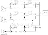
图2是本发明宽带阵列TDL处理结构示意图。FIG. 2 is a schematic diagram of a broadband array TDL processing structure of the present invention.
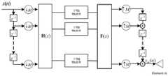
图3是本发明基于子带划分的阵列处理结构示意图。FIG. 3 is a schematic diagram of an array processing structure based on subband division in the present invention.
图4是宽带RTN算法发射波束天线方向图。Fig. 4 is a radiation beam antenna pattern diagram of the broadband RTN algorithm.
图5是子带RTN算法宽带发射波束天线方向图。Fig. 5 is a diagram of a sub-band RTN algorithm broadband transmit beam antenna pattern.
图6是本发明未划分子带的基于宽带MSINR算法宽带发射自适应波束形成图;其中,(a)是宽带MSINR算法发射波束天线方向,(b)是宽带MSINR算法零陷方向随频率变化图。Fig. 6 is the adaptive beamforming diagram based on the wideband MSINR algorithm wideband transmission of the present invention's undivided sub-band; Wherein, (a) is the wideband MSINR algorithm transmit beam antenna direction, (b) is the wideband MSINR algorithm null trap direction variation diagram with frequency .
图7是本发明划分子带的基于子带MSINR算法宽带发射自适应波束形成图;其中,(a)是子带MSINR算法发射波束天线方向,(b)是子带MSINR算法零陷方向随频率变化图。Fig. 7 is the sub-band MSINR algorithm broadband transmission adaptive beamforming diagram based on the sub-band division of the present invention; wherein, (a) is the sub-band MSINR algorithm transmit beam antenna direction, (b) is the sub-band MSINR algorithm null trap direction with frequency Change graph.
具体实施方式detailed description
下面结合附图对本发明的技术方案进行详细说明:The technical scheme of the present invention is described in detail below in conjunction with accompanying drawing:
一种基于子带最大信干噪比准则的宽带发射自适应波束形成方法,如图1所示,主要包括以下几个步骤:A wideband transmission adaptive beamforming method based on the subband maximum SINR criterion, as shown in Figure 1, mainly includes the following steps:
步骤一、设计宽带发射天线阵列,计算宽带阵列的输出信号。第m个阵元输出的信号xm(n)满足公式:Step 1: designing a broadband transmitting antenna array, and calculating the output signal of the broadband array. The signal xm (n) output by the mth array element satisfies the formula:

其中,x(n-k)指输出的离散信号x(n)向左平移k个单位,wm[k]指第m个阵元的第k个抽头的加权值,m=0,1,…,M-1,k=0,1,…,J-1,M是阵元总数,J是抽头延迟线系数。Among them, x(nk) refers to the output discrete signal x(n) shifting k units to the left, wm [k] refers to the weighted value of the kth tap of the mth array element, m=0,1,..., M-1, k=0, 1,..., J-1, M is the total number of array elements, and J is the tapped delay line coefficient.
步骤二、设计子带滤波器组,子带滤波器组可以分为分析滤波器组和综合滤波器组,分析滤波器组用于宽带信号的子带划分,综合滤波器组用于信号重构,子带滤波器组选用的离散傅里叶变换滤波器组。Step 2, design sub-band filter bank, sub-band filter bank can be divided into analysis filter bank and synthesis filter bank, analysis filter bank is used for the sub-band division of broadband signal, and synthesis filter bank is used for signal reconstruction , the discrete Fourier transform filter bank selected by the subband filter bank.
步骤三、利用子带滤波器组中的分析滤波器组完成宽带信号的子带划分。假设每个阵元后面有Q个子带处理通道,分析滤波器将宽带信号带宽均匀的划分为K个频点,信号方差矩阵和干扰噪声协方差矩阵满足以下公式:Step 3, using the analysis filter bank in the sub-band filter bank to complete the sub-band division of the broadband signal. Assuming that there are Q subband processing channels behind each array element, the analysis filter divides the broadband signal bandwidth evenly into K frequency points, and the signal variance matrix and interference noise covariance matrix satisfy the following formula:


其中,[·]H为转置共轭运算符,Rst-q是第q个子带信号的信号方差矩阵,Nst-q是第q个子带信号的干扰噪声协方差矩阵,K是频点总数,Vst-q(θ0,fl)表示频率为fl时的空时导引矢量,Hq(fl)表示频率为fl时第q个子带分析滤波器的频率响应,Fq(fl)表示频率为fl时第q个子带综合滤波器的频率响应,β是干扰信号的功率,σ2是零均值加性白噪声高斯过程的功率,I为单位矩阵,θ0是主瓣方向,θ1是期望形成零陷的方向,fl∈{f1,f2,...,fK}且l=1,2,...,K。Among them, [ ]H is the transpose conjugate operator, Rst-q is the signal variance matrix of the qth sub-band signal, Nst-q is the interference noise covariance matrix of the qth sub-band signal, K is the frequency point The total, Vst-q (θ0 ,fl ) represents the space-time steering vector at frequency fl , Hq (fl ) represents the frequency response of the qth subband analysis filter at frequency fl , Fq (fl ) represents the frequency response of the qth sub-band synthesis filter when the frequency is fl , β is the power of the interference signal, σ2 is the power of the zero-mean additive white noise Gaussian process, I is the identity matrix, θ0 is the direction of the main lobe, θ1 is the direction expected to form a null, fl ∈{f1 ,f2 ,...,fK } and l=1,2,...,K.
步骤四、基于子带最大信噪比准则计算各个子带自适应波束形成权矢量。第q个子带信号的信噪比SINRq满足公式:Step 4: Calculate the adaptive beamforming weight vector of each subband based on the maximum SNR criterion of the subband. The signal-to-noise ratio SINRq of the qth sub-band signal satisfies the formula:

其中,Wq是第q个子带信号的NJ×1维TDL权矢量。当SINRq最大时,可以得到权矢量最优解:Among them, Wq is the NJ×1-dimensional TDL weight vector of the qth subband signal. When the SINRq is the largest, the optimal solution of the weight vector can be obtained:

其中,子带最优TDL权矢量Wopt-q是
步骤五、利用子带滤波器组中的综合滤波器组将经过处理的宽带信号进行重构。求出各个子带的最优TDL权矢量,根据综合滤波器组的重构,经过发射自适应波束形成,第m个阵元输出的信号的频域表达式为:Step 5: Reconstruct the processed broadband signal by using the integrated filter bank in the subband filter bank. Calculate the optimal TDL weight vector of each sub-band, and according to the reconstruction of the integrated filter bank, after transmitting adaptive beamforming, the frequency domain expression of the signal output by the mth array element is:

其中,Ym(ejω)表示第m个阵元输出的信号的频域,wqm[k]表示第m个阵元第q个子带的第k个抽头加权值,X(ejω)表示原始宽带信号的频域,Hq(ejω)表示第q个子带的分析滤波器的频率响应,Fq(ejω)表示第q个子带的综合滤波器的频率响应。Among them, Ym (ejω ) represents the frequency domain of the signal output by the mth array element, wqm [k] represents the kth tap weight value of the qth subband of the mth array element, and X(ejω ) represents In the frequency domain of the original broadband signal, Hq (ejω ) represents the frequency response of the analysis filter for the qth subband, and Fq (ejω ) represents the frequency response of the synthesis filter for the qth subband.
最终输出的主瓣方向为θ0的宽带信号发射波束天线方向图为:The final output main lobe direction of the broadband signal transmitting beam antenna pattern of θ0 is:

其中,P(θ,f)表示宽带信号发射波束天线方向图,vst(θ,f)表示宽带信号发射方向为θ、频率为f时的空时导引矢量,Hq(f)表示频率为f时第q个子带分析滤波器的频率响应,Fq(f)表示频率为f时第q个子带综合滤波器的频率响应。Among them, P(θ,f) represents the broadband signal transmitting beam antenna pattern, vst (θ,f) represents the space-time steering vector when the broadband signal transmitting direction is θ and the frequency is f, Hq (f) represents the frequency When f is the frequency response of the qth subband analysis filter, Fq (f) represents the frequency response of the qth subband synthesis filter when the frequency is f.
在本具体实施例中,通过计算机仿真来进一步验证本方法的有效性,并且利用Peter G.Vouras的RTN波束形成算法与本发明的算法进行对比。本次仿真实验的参数设置如表1所示:In this specific embodiment, the effectiveness of the method is further verified by computer simulation, and the RTN beamforming algorithm of Peter G. Vouras is used for comparison with the algorithm of the present invention. The parameter settings of this simulation experiment are shown in Table 1:
表1系统仿真参数Table 1 System Simulation Parameters
此外,为了确保未划分子带波束形成时的时域宽带与划分子带后的时域宽度相同,未划分子带时TDL阶数J为15,划分子带时TDL阶数J为5,图2是本发明宽带阵列TDL处理结构示意图。In addition, in order to ensure that the time-domain broadband when beamforming is not divided into sub-bands is the same as the time-domain width after sub-band division, the TDL order J is 15 when the sub-bands are not divided, and the TDL order J is 5 when the sub-bands are divided, as shown in Fig. 2 is a schematic diagram of the broadband array TDL processing structure of the present invention.
本次仿真基于子带划分的阵列处理结构如图3所示,宽带信号x(n)经过分析滤波器,划分后的每个子带单独进行TDL处理,处理后的信号经过综合滤波器重构,得到最终处理后的输出信号ym(n)。This simulation is based on the array processing structure of sub-band division as shown in Figure 3. The broadband signal x(n) passes through the analysis filter, and each sub-band after division undergoes TDL processing separately, and the processed signal is reconstructed through the synthesis filter. The final processed output signal ym (n) is obtained.
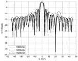
根据理论分析和仿真实验,RTN算法能够在宽带发射波束指定方向形成深度较深的零陷,其零陷方向不随频率变化。宽带RTN算法的发射波束天线方向图和子带RTN算法的发射波束天线方向图分别如图4和图5所示,可以看出相比较宽带RTN算法,子带RTN算法可以获得更深的零陷。According to theoretical analysis and simulation experiments, the RTN algorithm can form deep nulls in the specified direction of the broadband transmission beam, and the nulling direction does not change with frequency. The transmit beam antenna pattern of the wideband RTN algorithm and the transmit beam antenna pattern of the subband RTN algorithm are shown in Figure 4 and Figure 5, respectively. It can be seen that compared with the wideband RTN algorithm, the subband RTN algorithm can obtain deeper nulls.
没有划分子带的基于宽带MSINR宽带发射自适应波束形成算法的波束天线方向图如图6中的(a)所示,其零陷方向随频率变化如图6中的(b)所示,划分子带的基于子带MSINR宽带发射自适应波束形成算法的波束天线方向图如图7中的(a)所示,其零陷方向随频率变化如图7中的(b)所示。从图6中的(b)和图7中的(b)中均可以看出,当角度为20°时,即干扰方向上,是一条竖直的线条,这说明宽带MSINR算法和子带MSINR算法均可以抑制孔径渡越效应,其宽带发射波束上形成的零陷指向不随频率变化。The beam antenna pattern of the adaptive beamforming algorithm based on broadband MSINR broadband transmission without dividing subbands is shown in (a) in Figure 6, and its null direction varies with frequency as shown in (b) in Figure 6. The beam antenna pattern of subband MSINR wideband transmission adaptive beamforming algorithm based on subband is shown in (a) in Figure 7, and its nulling direction varies with frequency as shown in (b) in Figure 7. It can be seen from (b) in Figure 6 and (b) in Figure 7 that when the angle is 20°, that is, in the interference direction, there is a vertical line, which shows that the wideband MSINR algorithm and the subband MSINR algorithm Both can suppress the aperture transition effect, and the null point formed on the broadband transmitting beam does not change with the frequency.
不同算法仿真实验得到的零陷深度对比如表2所示:The comparison of the zero-trap depths obtained by different algorithm simulation experiments is shown in Table 2:
表2不同算法形成零陷深度对比(dB)Table 2 Comparison of null-trap depths formed by different algorithms (dB)
从表2可以看出,基于MSINR准则算法形成的零陷深度明显比RTN算法的深,且子带划分的基于MSINR准则的宽带发射自适应波束形成算法性能最强。宽带MSINR算法所形成的波束零陷深度在最低频率、中心频率、最高频率均提高了20dB左右,在中心频率时深度可达73dB,性能明显优于RTN算法。同时,子带MSINR算法相对于宽带MSINR算法,零陷深度进一步提升,中心频率零陷深度达到86.2dB,对干扰的抑制性能进一步加强,并且相对于宽带MSINR算法,TDL的抽头采样频率降低为原来的1/5,更利于工程实现。It can be seen from Table 2 that the null depth formed by the MSINR criterion algorithm is obviously deeper than that of the RTN algorithm, and the performance of the wideband transmission adaptive beamforming algorithm based on the MSINR criterion based on subband division is the strongest. The null depth of the beam formed by the broadband MSINR algorithm is increased by about 20dB at the lowest frequency, the center frequency, and the highest frequency, and the depth can reach 73dB at the center frequency, and the performance is significantly better than that of the RTN algorithm. At the same time, compared with the wideband MSINR algorithm, the subband MSINR algorithm further improves the null depth, and the center frequency null depth reaches 86.2dB, which further enhances the interference suppression performance. Compared with the wideband MSINR algorithm, the TDL tap sampling frequency is reduced to the original 1/5 of that, which is more conducive to engineering realization.
上面结合附图对本发明的实施方式作了详细地说明,但是本发明并不局限于上述实施方式,在本领域普通技术人员所具备的知识范围内,还可以在不脱离本发明宗旨的前提下做出各种变化。The embodiments of the present invention have been described in detail above in conjunction with the accompanying drawings, but the present invention is not limited to the above embodiments, within the knowledge of those of ordinary skill in the art, you can also Make various changes.
Claims (6)


Priority Applications (1)
| Application Number | Priority Date | Filing Date | Title |
|---|---|---|---|
| CN201810895372.3ACN109188366B (en) | 2018-08-08 | 2018-08-08 | Adaptive Beamforming Method for Wideband Transmission Based on Subband Maximum SNR Criterion |
Applications Claiming Priority (1)
| Application Number | Priority Date | Filing Date | Title |
|---|---|---|---|
| CN201810895372.3ACN109188366B (en) | 2018-08-08 | 2018-08-08 | Adaptive Beamforming Method for Wideband Transmission Based on Subband Maximum SNR Criterion |
Publications (2)
| Publication Number | Publication Date |
|---|---|
| CN109188366A CN109188366A (en) | 2019-01-11 |
| CN109188366Btrue CN109188366B (en) | 2023-01-17 |
Family
ID=64920478
Family Applications (1)
| Application Number | Title | Priority Date | Filing Date |
|---|---|---|---|
| CN201810895372.3AActiveCN109188366B (en) | 2018-08-08 | 2018-08-08 | Adaptive Beamforming Method for Wideband Transmission Based on Subband Maximum SNR Criterion |
Country Status (1)
| Country | Link |
|---|---|
| CN (1) | CN109188366B (en) |
Families Citing this family (3)
| Publication number | Priority date | Publication date | Assignee | Title |
|---|---|---|---|---|
| CN110166098B (en)* | 2019-04-25 | 2022-02-01 | 河海大学 | Adaptive beam forming method for broadband phase-only transmission |
| CN112420068B (en)* | 2020-10-23 | 2022-05-03 | 四川长虹电器股份有限公司 | Quick self-adaptive beam forming method based on Mel frequency scale frequency division |
| CN116505994B (en)* | 2023-06-26 | 2023-09-01 | 成都金支点科技有限公司 | Multi-beam forming method and device |
Citations (7)
| Publication number | Priority date | Publication date | Assignee | Title |
|---|---|---|---|---|
| WO2004088794A1 (en)* | 2003-04-01 | 2004-10-14 | Koninklijke Philips Electronics N.V. | A method and apparatus for beamforming based on broadband antenna |
| JP2006258581A (en)* | 2005-03-16 | 2006-09-28 | Toshiba Corp | Radar signal processing device |
| CN102608588A (en)* | 2012-03-14 | 2012-07-25 | 西安电子科技大学 | Broadband sub-matrix adaptive beamforming method based on sub-band decomposition |
| CN104243001A (en)* | 2014-08-13 | 2014-12-24 | 上海无线电设备研究所 | Broadband beam switching system and method |
| CN104967506A (en)* | 2015-04-27 | 2015-10-07 | 西安空间无线电技术研究所 | A Resource Multiplexed Completely Reconfigured Subband Synthesis Processing Method |
| CN106301498A (en)* | 2016-08-17 | 2017-01-04 | 河海大学 | Sub-band processing method and the wideband adaptive wave beam acquisition methods of frequency vacant level connection |
| CN107748354A (en)* | 2017-08-08 | 2018-03-02 | 中国电子科技集团公司第三十八研究所 | Wide band digital beam-forming device based on analysis and synthesis |
Family Cites Families (1)
| Publication number | Priority date | Publication date | Assignee | Title |
|---|---|---|---|---|
| US7817967B2 (en)* | 2005-06-21 | 2010-10-19 | Atc Technologies, Llc | Communications systems including adaptive antenna systems and methods for inter-system and intra-system interference reduction |
- 2018
- 2018-08-08CNCN201810895372.3Apatent/CN109188366B/enactiveActive
Patent Citations (7)
| Publication number | Priority date | Publication date | Assignee | Title |
|---|---|---|---|---|
| WO2004088794A1 (en)* | 2003-04-01 | 2004-10-14 | Koninklijke Philips Electronics N.V. | A method and apparatus for beamforming based on broadband antenna |
| JP2006258581A (en)* | 2005-03-16 | 2006-09-28 | Toshiba Corp | Radar signal processing device |
| CN102608588A (en)* | 2012-03-14 | 2012-07-25 | 西安电子科技大学 | Broadband sub-matrix adaptive beamforming method based on sub-band decomposition |
| CN104243001A (en)* | 2014-08-13 | 2014-12-24 | 上海无线电设备研究所 | Broadband beam switching system and method |
| CN104967506A (en)* | 2015-04-27 | 2015-10-07 | 西安空间无线电技术研究所 | A Resource Multiplexed Completely Reconfigured Subband Synthesis Processing Method |
| CN106301498A (en)* | 2016-08-17 | 2017-01-04 | 河海大学 | Sub-band processing method and the wideband adaptive wave beam acquisition methods of frequency vacant level connection |
| CN107748354A (en)* | 2017-08-08 | 2018-03-02 | 中国电子科技集团公司第三十八研究所 | Wide band digital beam-forming device based on analysis and synthesis |
Non-Patent Citations (2)
| Title |
|---|
| 基于子带SDL的宽带自适应波束形成;陈晖 等;《信号处理》;20121225;第1686-1688页* |
| 自适应波束形成;杨英科 等;《雷达测量与应用》;国防工业出版社;20110430;第148-149页* |
Also Published As
| Publication number | Publication date |
|---|---|
| CN109188366A (en) | 2019-01-11 |
Similar Documents
| Publication | Publication Date | Title |
|---|---|---|
| CN105785331B (en) | A kind of external illuminators-based radar direct wave restoration methods using blind source separating | |
| CN109188366B (en) | Adaptive Beamforming Method for Wideband Transmission Based on Subband Maximum SNR Criterion | |
| CN112363119A (en) | Broadband robust transmission self-adaptive beam forming method based on RUWO processing | |
| CN109507643B (en) | Method for widening null in sidelobe cancellation | |
| CN108845294B (en) | Broadband emission self-adaptive beam forming method based on sub-band linear multi-constraint minimum variance criterion | |
| CN106646388A (en) | MIMO radar anti-interference method based on nested array | |
| CN110045334A (en) | Sidelobe null Beamforming Method | |
| CN110166098B (en) | Adaptive beam forming method for broadband phase-only transmission | |
| CN113176565A (en) | Multi-channel SAR distance ambiguity suppression method and device | |
| CN111537958A (en) | A Wide Linear Reduced-Rank Minimum Entropy Distortion-Free Response Beamforming Method | |
| Godara et al. | Convolution constraints for broadband antenna arrays | |
| Liu et al. | Design and analysis of broadband beamspace adaptive arrays | |
| CN108828536B (en) | Design method of broadband transmit digital beamforming interference based on second-order cone planning | |
| CN111817765B (en) | Generalized sidelobe cancellation broadband beam forming method based on frequency constraint | |
| CN113671449A (en) | Sidelobe interference suppression method for MIMO radar based on minimum redundant linear array | |
| CN115765814A (en) | Broadband millimeter wave hybrid array beam tilt compensation method | |
| Wang et al. | Wideband Transmitting Adaptive Digital Beamforming Based on Sub-Band Multiple Linear Constrained Minimum Variance Method | |
| Liu et al. | A virtual space-time adaptive beamforming method for space-time antijamming | |
| CN106209125B (en) | A universal new broadband beamforming system and implementation method | |
| Edussooriya et al. | Low-complexity wideband transmit array using variable-precision 2-D sparse FIR digital filters | |
| Job et al. | A STUDY ON ADAPTIVE CONSTRAINT GENERALISED SIDELOBE CANCELLER FOR OPTIMIZING BEAM AND THE SPECTRUM ANALYSIS OF NARROW BAND AND WIDE BAND SIGNAL. | |
| Rao et al. | Design and analysis of array weighted wideband antenna using FRFT | |
| Liu et al. | Analysis and a novel design of the beamspace broadband adaptive array | |
| Godara et al. | An optimized sector nulling technique for broadband antenna array | |
| Godara et al. | New constraints for broadband beamformers without steering delays |
Legal Events
| Date | Code | Title | Description |
|---|---|---|---|
| PB01 | Publication | ||
| PB01 | Publication | ||
| SE01 | Entry into force of request for substantive examination | ||
| SE01 | Entry into force of request for substantive examination | ||
| GR01 | Patent grant | ||
| GR01 | Patent grant |