CN109167611B - Radio frequency system and electronic equipment - Google Patents
Radio frequency system and electronic equipmentDownload PDFInfo
- Publication number
- CN109167611B CN109167611BCN201811013431.6ACN201811013431ACN109167611BCN 109167611 BCN109167611 BCN 109167611BCN 201811013431 ACN201811013431 ACN 201811013431ACN 109167611 BCN109167611 BCN 109167611B
- Authority
- CN
- China
- Prior art keywords
- switch
- radio frequency
- port
- module
- receiving
- Prior art date
- Legal status (The legal status is an assumption and is not a legal conclusion. Google has not performed a legal analysis and makes no representation as to the accuracy of the status listed.)
- Active
Links
Images


Classifications
- H—ELECTRICITY
- H04—ELECTRIC COMMUNICATION TECHNIQUE
- H04B—TRANSMISSION
- H04B1/00—Details of transmission systems, not covered by a single one of groups H04B3/00 - H04B13/00; Details of transmission systems not characterised by the medium used for transmission
- H04B1/005—Details of transmission systems, not covered by a single one of groups H04B3/00 - H04B13/00; Details of transmission systems not characterised by the medium used for transmission adapting radio receivers, transmitters andtransceivers for operation on two or more bands, i.e. frequency ranges
- H04B1/0053—Details of transmission systems, not covered by a single one of groups H04B3/00 - H04B13/00; Details of transmission systems not characterised by the medium used for transmission adapting radio receivers, transmitters andtransceivers for operation on two or more bands, i.e. frequency ranges with common antenna for more than one band
- H04B1/006—Details of transmission systems, not covered by a single one of groups H04B3/00 - H04B13/00; Details of transmission systems not characterised by the medium used for transmission adapting radio receivers, transmitters andtransceivers for operation on two or more bands, i.e. frequency ranges with common antenna for more than one band using switches for selecting the desired band
- H—ELECTRICITY
- H04—ELECTRIC COMMUNICATION TECHNIQUE
- H04B—TRANSMISSION
- H04B7/00—Radio transmission systems, i.e. using radiation field
- H04B7/02—Diversity systems; Multi-antenna system, i.e. transmission or reception using multiple antennas
- H04B7/04—Diversity systems; Multi-antenna system, i.e. transmission or reception using multiple antennas using two or more spaced independent antennas
- H04B7/0404—Diversity systems; Multi-antenna system, i.e. transmission or reception using multiple antennas using two or more spaced independent antennas the mobile station comprising multiple antennas, e.g. to provide uplink diversity
- H—ELECTRICITY
- H04—ELECTRIC COMMUNICATION TECHNIQUE
- H04B—TRANSMISSION
- H04B1/00—Details of transmission systems, not covered by a single one of groups H04B3/00 - H04B13/00; Details of transmission systems not characterised by the medium used for transmission
- H04B1/02—Transmitters
- H04B1/03—Constructional details, e.g. casings, housings
- H04B1/034—Portable transmitters
- H—ELECTRICITY
- H04—ELECTRIC COMMUNICATION TECHNIQUE
- H04B—TRANSMISSION
- H04B1/00—Details of transmission systems, not covered by a single one of groups H04B3/00 - H04B13/00; Details of transmission systems not characterised by the medium used for transmission
- H04B1/02—Transmitters
- H04B1/04—Circuits
- H—ELECTRICITY
- H04—ELECTRIC COMMUNICATION TECHNIQUE
- H04B—TRANSMISSION
- H04B1/00—Details of transmission systems, not covered by a single one of groups H04B3/00 - H04B13/00; Details of transmission systems not characterised by the medium used for transmission
- H04B1/38—Transceivers, i.e. devices in which transmitter and receiver form a structural unit and in which at least one part is used for functions of transmitting and receiving
- H04B1/40—Circuits
- H04B1/401—Circuits for selecting or indicating operating mode
- H—ELECTRICITY
- H04—ELECTRIC COMMUNICATION TECHNIQUE
- H04B—TRANSMISSION
- H04B7/00—Radio transmission systems, i.e. using radiation field
- H04B7/02—Diversity systems; Multi-antenna system, i.e. transmission or reception using multiple antennas
- H04B7/04—Diversity systems; Multi-antenna system, i.e. transmission or reception using multiple antennas using two or more spaced independent antennas
- H04B7/0413—MIMO systems
- H—ELECTRICITY
- H04—ELECTRIC COMMUNICATION TECHNIQUE
- H04M—TELEPHONIC COMMUNICATION
- H04M1/00—Substation equipment, e.g. for use by subscribers
- H04M1/02—Constructional features of telephone sets
- H04M1/0202—Portable telephone sets, e.g. cordless phones, mobile phones or bar type handsets
- H04M1/026—Details of the structure or mounting of specific components
- H—ELECTRICITY
- H04—ELECTRIC COMMUNICATION TECHNIQUE
- H04B—TRANSMISSION
- H04B1/00—Details of transmission systems, not covered by a single one of groups H04B3/00 - H04B13/00; Details of transmission systems not characterised by the medium used for transmission
- H04B1/02—Transmitters
- H04B1/04—Circuits
- H04B2001/0408—Circuits with power amplifiers
- H—ELECTRICITY
- H04—ELECTRIC COMMUNICATION TECHNIQUE
- H04M—TELEPHONIC COMMUNICATION
- H04M1/00—Substation equipment, e.g. for use by subscribers
- H04M1/02—Constructional features of telephone sets
- H04M1/0202—Portable telephone sets, e.g. cordless phones, mobile phones or bar type handsets
- H04M1/026—Details of the structure or mounting of specific components
- H04M1/0277—Details of the structure or mounting of specific components for a printed circuit board assembly
- Y—GENERAL TAGGING OF NEW TECHNOLOGICAL DEVELOPMENTS; GENERAL TAGGING OF CROSS-SECTIONAL TECHNOLOGIES SPANNING OVER SEVERAL SECTIONS OF THE IPC; TECHNICAL SUBJECTS COVERED BY FORMER USPC CROSS-REFERENCE ART COLLECTIONS [XRACs] AND DIGESTS
- Y02—TECHNOLOGIES OR APPLICATIONS FOR MITIGATION OR ADAPTATION AGAINST CLIMATE CHANGE
- Y02D—CLIMATE CHANGE MITIGATION TECHNOLOGIES IN INFORMATION AND COMMUNICATION TECHNOLOGIES [ICT], I.E. INFORMATION AND COMMUNICATION TECHNOLOGIES AIMING AT THE REDUCTION OF THEIR OWN ENERGY USE
- Y02D30/00—Reducing energy consumption in communication networks
- Y02D30/70—Reducing energy consumption in communication networks in wireless communication networks
Landscapes
- Engineering & Computer Science (AREA)
- Signal Processing (AREA)
- Computer Networks & Wireless Communication (AREA)
- Transceivers (AREA)
- Mobile Radio Communication Systems (AREA)
Abstract
Description
Translated fromChinese技术领域technical field
本申请涉及电子设备技术领域,具体涉及一种射频系统、天线切换控制方法及相关产品。The present application relates to the technical field of electronic equipment, and in particular to a radio frequency system, an antenna switching control method and related products.
背景技术Background technique
随着智能手机等电子设备的大量普及应用,智能手机能够支持的应用越来越多,功能越来越强大,智能手机向着多样化、个性化的方向发展,成为用户生活中不可缺少的电子用品。第四代移动通信技术(the 4th Generation mobile communication technology,4G)移动通信系统中电子设备一般采用单天线或双天线射频系统架构,目前第五代移动通信技术(5th-Generation,5G)移动通信系统新空口(New Radio,NR)系统中提出支持4天线组的射频系统架构需求。With the widespread application of electronic devices such as smart phones, smart phones can support more and more applications, and their functions are becoming more and more powerful. . The electronic equipment in the 4th Generation mobile communication technology (4G) mobile communication system generally adopts a single-antenna or dual-antenna radio frequency system architecture. At present, the fifth-generation mobile communication technology (5th-Generation, 5G) mobile communication system A radio frequency system architecture requirement supporting four antenna groups is proposed in a New Radio (NR) system.
发明内容SUMMARY OF THE INVENTION
本申请实施例提供了一种射频系统、天线切换控制方法及相关产品,以期提升各通道灵敏度,相比分离器件搭建,集成度更高,面积/成本/功耗更优。Embodiments of the present application provide a radio frequency system, an antenna switching control method, and related products, in order to improve the sensitivity of each channel, and have higher integration and better area/cost/power consumption than separate device construction.
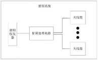
第一方面,本申请实施例提供一种射频系统,包括射频收发器、射频处理电路和4个天线组,所述射频收发器连接所述射频处理电路,所述射频处理电路连接所述4个天线组,每个天线组包括2支天线;In a first aspect, an embodiment of the present application provides a radio frequency system, including a radio frequency transceiver, a radio frequency processing circuit, and four antenna groups, the radio frequency transceiver is connected to the radio frequency processing circuit, and the radio frequency processing circuit is connected to the four antenna groups. Antenna groups, each antenna group includes 2 antennas;
所述射频系统支持2个频段,所述射频处理电路包括与所述4个天线组对应的4个模组,每个模组连接1个天线组,且每个模组靠近所连接的天线组设置,所述射频处理电路还包括至少1个接收端口选择开关,每个接收端口选择开关连接射频收发器的信号接收端口,以及连接所述发射模组的外接端口,所述4个模组包括1个发射模组和3个接收模组,所述射频系统支持4天线信道探测参考信号SRS发射轮询。The radio frequency system supports two frequency bands, the radio frequency processing circuit includes four modules corresponding to the four antenna groups, each module is connected to one antenna group, and each module is close to the connected antenna group Setting, the radio frequency processing circuit further includes at least one receiving port selection switch, each receiving port selection switch is connected to the signal receiving port of the radio frequency transceiver, and is connected to the external port of the transmitting module, and the four modules include 1 transmitting module and 3 receiving modules, the radio frequency system supports 4-antenna channel sounding reference signal SRS transmission polling.
第二方面,本申请实施例提供一种电子设备,包括射频收发器、射频处理电路和4个天线组,所述射频收发器连接所述射频处理电路,所述射频处理电路连接所述4个天线组,每个天线组包括2支天线;所述射频系统支持2个频段,所述射频处理电路包括与所述4个天线组对应的4个模组,每个模组连接1个天线组,且每个模组靠近所连接的天线组设置,所述射频处理电路还包括至少1个接收端口选择开关,每个接收端口选择开关连接射频收发器的信号接收端口,以及连接所述发射模组的外接端口,所述4个模组包括1个发射模组和3个接收模组,所述射频系统支持4天线信道探测参考信号 SRS发射轮询;In a second aspect, an embodiment of the present application provides an electronic device, including a radio frequency transceiver, a radio frequency processing circuit, and four antenna groups, the radio frequency transceiver is connected to the radio frequency processing circuit, and the radio frequency processing circuit is connected to the four antenna groups Antenna groups, each antenna group includes two antennas; the radio frequency system supports two frequency bands, the radio frequency processing circuit includes four modules corresponding to the four antenna groups, and each module is connected to one antenna group , and each module is set close to the connected antenna group, the radio frequency processing circuit also includes at least one receiving port selection switch, each receiving port selection switch is connected to the signal receiving port of the radio frequency transceiver, and is connected to the transmitting module. The external port of the group, the 4 modules include 1 transmitting module and 3 receiving modules, and the radio frequency system supports 4 antenna channel sounding reference signal SRS transmission polling;
所述电子设备至少包括以下任意一种:移动终端、基站。The electronic device includes at least any one of the following: a mobile terminal and a base station.
第三方面,本申请实施例提供一种天线切换控制方法,应用于电子设备,所述电子设备包括射频收发器、射频处理电路和4个天线组,所述射频收发器连接所述射频处理电路,所述射频处理电路连接所述4个天线组;所述方法包括:In a third aspect, an embodiment of the present application provides an antenna switching control method, which is applied to an electronic device. The electronic device includes a radio frequency transceiver, a radio frequency processing circuit, and four antenna groups, and the radio frequency transceiver is connected to the radio frequency processing circuit. , the radio frequency processing circuit is connected to the four antenna groups; the method includes:
控制所述射频系统中所述射频收发器的目标频段的发射端口与目标天线组之间的发射通路导通,通过所述目标天线组中的天线发射信号,以实现所述射频系统的4天线SRS发射轮询功能。Control the transmission path between the transmission port of the target frequency band of the radio frequency transceiver in the radio frequency system and the target antenna group to conduct, and transmit signals through the antennas in the target antenna group, so as to realize the four antennas of the radio frequency system SRS transmits polling function.
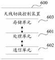
第四方面,本申请实施例提供一种天线切换控制装置,应用于电子设备,所述电子设备包括射频收发器、射频处理电路和4个天线组,所述射频收发器连接所述射频处理电路,所述射频处理电路连接所述4个天线组;所述天线切换控制装置包括处理单元和通信单元,其中,In a fourth aspect, an embodiment of the present application provides an antenna switching control device, which is applied to an electronic device. The electronic device includes a radio frequency transceiver, a radio frequency processing circuit, and four antenna groups, and the radio frequency transceiver is connected to the radio frequency processing circuit. , the radio frequency processing circuit is connected to the four antenna groups; the antenna switching control device includes a processing unit and a communication unit, wherein,
所述处理单元,用于通过所述通信单元控制所述射频系统中所述射频收发器的目标频段的发射端口与目标天线组之间的发射通路导通,通过所述目标天线组中的天线发射信号,以实现所述射频系统的4天线SRS发射轮询功能。The processing unit is configured to control the transmission path between the transmission port of the target frequency band of the radio frequency transceiver in the radio frequency system and the target antenna group to conduct through the communication unit, through the antenna in the target antenna group A signal is transmitted to realize the 4-antenna SRS transmission polling function of the radio frequency system.
第五方面,本申请实施例提供一种电子设备,包括处理器、存储器、通信接口,以及一个或多个程序,所述一个或多个程序被存储在所述存储器中,并且被配置由所述处理器执行,所述程序包括用于执行如第三方面所述的方法中的步骤的指令。In a fifth aspect, embodiments of the present application provide an electronic device, including a processor, a memory, a communication interface, and one or more programs, where the one or more programs are stored in the memory and configured by the executed by the processor, the program comprising instructions for performing the steps in the method of the third aspect.
第六方面,本申请实施例提供一种计算机可读存储介质,存储用于电子数据交换的计算机程序,其中,所述计算机程序使得计算机执行如第三方面所述的方法。In a sixth aspect, an embodiment of the present application provides a computer-readable storage medium storing a computer program for electronic data exchange, wherein the computer program causes a computer to execute the method according to the third aspect.
可以看出,本申请实施例中,由于射频系统中的各个模组靠近对应天线组设置,且仅需要接收模组和发射模组即可构建核心处理电路,有利于提升各通道灵敏度,相比分离器件搭建,集成度更高,面积/成本/功耗更优。It can be seen that in the embodiment of the present application, since each module in the radio frequency system is set close to the corresponding antenna group, and only the receiving module and the transmitting module are needed to construct the core processing circuit, it is beneficial to improve the sensitivity of each channel. Separate device construction, higher integration, better area/cost/power consumption.
附图说明Description of drawings
为了更清楚地说明本申请实施例或现有技术中的技术方案,下面将对实施例或现有技术描述中所需要使用的附图作简单地介绍,显而易见地,下面描述中的附图仅仅是本申请的一些实施例,对于本领域普通技术人员来讲,在不付出创造性劳动的前提下,还可以根据这些附图获得其他的附图。In order to more clearly illustrate the embodiments of the present application or the technical solutions in the prior art, the following briefly introduces the accompanying drawings required for the description of the embodiments or the prior art. Obviously, the drawings in the following description are only These are some embodiments of the present application. For those of ordinary skill in the art, other drawings can also be obtained based on these drawings without any creative effort.
图1是本申请实施例提供的一种接收模组的结构示意图;1 is a schematic structural diagram of a receiving module provided by an embodiment of the present application;
图2A是本申请实施例提供的一种发射模组的结构示意图;2A is a schematic structural diagram of a launch module provided by an embodiment of the present application;
图2B是本申请实施例提供的另一种发射模组的结构示意图;2B is a schematic structural diagram of another launch module provided by an embodiment of the present application;
图3是本申请实施例提供的一种射频系统的结构示意图;3 is a schematic structural diagram of a radio frequency system provided by an embodiment of the present application;
图3A是本申请实施例提供的另一种射频系统的结构示意图;3A is a schematic structural diagram of another radio frequency system provided by an embodiment of the present application;
图3B是本申请实施例提供的另一种射频系统的结构示意图;3B is a schematic structural diagram of another radio frequency system provided by an embodiment of the present application;
图3C是本申请实施例提供的另一种射频系统的结构示意图;3C is a schematic structural diagram of another radio frequency system provided by an embodiment of the present application;
图3D是本申请实施例提供的另一种射频系统的结构示意图;FIG. 3D is a schematic structural diagram of another radio frequency system provided by an embodiment of the present application;
图4是本申请实施例提供的一种天线切换控制方法的流程示意图;4 is a schematic flowchart of an antenna switching control method provided by an embodiment of the present application;
图5是本申请实施例提供的一种电子设备的结构示意图;5 is a schematic structural diagram of an electronic device provided by an embodiment of the present application;
图6是本申请实施例提供的一种天线切换控制装置的功能单元组成框图。FIG. 6 is a block diagram of functional units of an antenna switching control apparatus provided by an embodiment of the present application.
具体实施方式Detailed ways
下面将结合本申请实施例中的附图,对本申请实施例中的技术方案进行清楚、完整地描述,显然,所描述的实施例仅仅是本申请一部分实施例,而不是全部的实施例。基于本申请中的实施例,本领域普通技术人员在没有付出创造性劳动前提下所获得的所有其他实施例,都属于本申请保护的范围。The technical solutions in the embodiments of the present application will be clearly and completely described below with reference to the drawings in the embodiments of the present application. Obviously, the described embodiments are only a part of the embodiments of the present application, but not all of the embodiments. Based on the embodiments in the present application, all other embodiments obtained by those of ordinary skill in the art without creative efforts fall within the protection scope of the present application.
本申请的说明书和权利要求书及上述附图中的术语“第一”、“第二”等是用于区别不同对象,而不是用于描述特定顺序。此外,术语“包括”和“具有”以及它们任何变形,意图在于覆盖不排他的包含。例如包含了一系列步骤或单元的过程、方法、系统、产品或设备没有限定于已列出的步骤或单元,而是可选地还包括没有列出的步骤或单元,或可选地还包括对于这些过程、方法、产品或设备固有的其他步骤或单元。The terms "first", "second" and the like in the description and claims of the present application and the above drawings are used to distinguish different objects, rather than to describe a specific order. Furthermore, the terms "comprising" and "having" and any variations thereof are intended to cover non-exclusive inclusion. For example, a process, method, system, product or device comprising a series of steps or units is not limited to the listed steps or units, but optionally also includes unlisted steps or units, or optionally also includes For other steps or units inherent to these processes, methods, products or devices.
在本文中提及“实施例”意味着,结合实施例描述的特定特征、结构或特性可以包含在本申请的至少一个实施例中。在说明书中的各个位置出现该短语并不一定均是指相同的实施例,也不是与其它实施例互斥的独立的或备选的实施例。本领域技术人员显式地和隐式地理解的是,本文所描述的实施例可以与其它实施例相结合。Reference herein to an "embodiment" means that a particular feature, structure, or characteristic described in connection with the embodiment can be included in at least one embodiment of the present application. The appearances of the phrase in various places in the specification are not necessarily all referring to the same embodiment, nor a separate or alternative embodiment that is mutually exclusive of other embodiments. It is explicitly and implicitly understood by those skilled in the art that the embodiments described herein may be combined with other embodiments.
本申请实施例所涉及到的电子设备可以包括各种具有无线通信功能的手持设备、车载设备、可穿戴设备、计算设备或连接到无线调制解调器的其他处理设备,以及各种形式的用户设备(User Equipment,UE),移动台(Mobile Station,MS),终端设备(terminaldevice)等等。为方便描述,上面提到的设备统称为电子设备。The electronic devices involved in the embodiments of the present application may include various handheld devices with wireless communication functions, vehicle-mounted devices, wearable devices, computing devices, or other processing devices connected to wireless modems, as well as various forms of user equipment (User Equipment). Equipment, UE), mobile station (Mobile Station, MS), terminal device (terminal device) and so on. For convenience of description, the devices mentioned above are collectively referred to as electronic devices.
目前,手机的SRS切换switching4天线发射功能是中国移动通信集团CMCC在《中国移动5G规模试验技术白皮书_终端》中的必选项,在第三代合作伙伴计划3GPP中为可选,其主要目的是为了基站通过测量手机4天线上行信号,进而确认4路信道质量及参数,根据信道互易性再针对4路信道做下行最优化多输入多输出Massive MIMO天线阵列的波束赋形,最终使下行4x4MIMO获得最佳数据传输性能。At present, the SRS switching switching4 antenna transmission function of the mobile phone is a mandatory option in the "China Mobile 5G Scale Test Technology White Paper_Terminal" by China Mobile Communications Group CMCC, and it is optional in the third generation partnership program 3GPP. Its main purpose is to In order for the base station to measure the uplink signals of the 4 antennas of the mobile phone, and then confirm the quality and parameters of the 4 channels, according to the channel reciprocity and then optimize the beamforming of the MIMO Massive MIMO antenna array for the downlink according to the channel reciprocity, and finally make the downlink 4x4MIMO. Get the best data transfer performance.
其中,所述电子设备具体可以是5G NR手机终端或其他5G NR终端设备,例如客户签约设备(Customer Premise Equipment,CPE)或者便携式宽带无线装置(Mobile Wifi,MIFI)。The electronic equipment may specifically be a 5G NR mobile phone terminal or other 5G NR terminal equipment, such as Customer Premise Equipment (CPE) or a portable broadband wireless device (Mobile Wifi, MIFI).
定义本申请实施例所呈现的射频系统中的模组(包括接收模组和发射模组)的原因如下,①5G NR需要下行4x4MIMO或4路分集接收;②TX SRS switching4天线轮发 (可选);③发射天线切换功能(可选)④sub 6GHz的频段范围在3.3~4.2G及4.4~5G。此频段相对LTE 600~2700MHz的频段,频率更高。因此RF cable(同轴线)从主板一侧到另一侧,以及从主板到副板(又称为下板),RF cable损耗较大;The reasons for defining the modules (including the receiving module and the transmitting module) in the radio frequency system presented in the embodiment of this application are as follows: ①5G NR requires downlink 4x4MIMO or 4-way diversity reception; ②TX SRS switching4 antenna rotation (optional); ③Transmitting antenna switching function (optional) ④The frequency range of sub 6GHz is 3.3~4.2G and 4.4~5G. This frequency band is higher than the LTE 600-2700MHz frequency band. Therefore, the RF cable (coaxial cable) from one side of the main board to the other side, and from the main board to the sub-board (also known as the lower board), has a large loss of RF cable;
而系统灵敏度公式Ps=10lg(KT)+10lg(BW)+NF+SNR,And the system sensitivity formula Ps=10lg(KT)+10lg(BW)+NF+SNR,
K:波尔兹曼常数(1.38×E-23单位:J/K)K: Boltzmann constant (1.38×E-23 unit: J/K)
T:绝对温度(273.15单位:K)公式中采用20℃常温,故T=293.15T: Absolute temperature (273.15 unit: K) The normal temperature of 20°C is used in the formula, so T=293.15
NF:噪声系数Noise figureNF: Noise figure Noise figure
BW:带宽BW: Bandwidth
SNR:最小解调门限,由平台供应商(高通,MTK)基带算法决定。SNR: Minimum demodulation threshold, determined by the platform provider (Qualcomm, MTK) baseband algorithm.
在此公式中,K,T为固定常数,BW由测试带宽确认,SNR由系统基带算法决定,In this formula, K, T are fixed constants, BW is confirmed by the test bandwidth, SNR is determined by the system baseband algorithm,
NF公式如下,The NF formula is as follows,

其中NF1=ILpre-1st LNA+NF1st LNA其中ILpre-1st LNA为第一级LNA之前的插损,NF1st LNA为第一级的噪声系数。这2者是整个NF的主要贡献部分。Wherein NF1 =ILpre-1st LNA +NF1st LNA , wherein ILpre-1st LNA is the insertion loss before the first stage LNA, and NF1st LNA is the noise figure of the first stage. These two are the main contributing parts of the entire NF.
而
综上所述,在射频前端设计中,为提升灵敏度,就需要减小整个NF值。而NF1又是主要贡献者,NF1中,除了使用外置LNA来减小NF1st LNA外,如何减小ILpre-1st LNA变为至关重要的改善手段,即如何减小第一级LNA之前的插损。To sum up, in the RF front-end design, in order to improve the sensitivity, it is necessary to reduce the entire NF value. And NF1 is the main contributor. In NF1 , in addition to using an external LNA to reduce the NF1st LNA , how to reduce the ILpre-1st LNA becomes a crucial improvement method, that is, how to reduce the first level Insertion loss before LNA.
本申请实施例中,定义了一种5G NR射频系统,可以将此射频系统中的接收模组和发射模组放置在天线附近,从而达到减小第一级LNA之前插损,改善系统灵敏度的目的。In the embodiment of this application, a 5G NR radio frequency system is defined, and the receiving module and the transmitting module in the radio frequency system can be placed near the antenna, so as to reduce the insertion loss before the first-level LNA and improve the sensitivity of the system. Purpose.
第一方面,本申请实施例提出一种接收模组,应用于射频系统,所述射频系统支持2个频段,且支持4天线信道探测参考信号SRS发射轮询;所述接收模组包括2路信号接收通道、第一切换开关、第二切换开关;所述第一切换开关连接所述2路信号接收通道,所述2路信号接收通道连接所述第二切换开关,所述第一切换开关或所述第二切换开关包括n1Pn2T开关,每路信号接收通道包括滤波器Filter和低噪声放大器LNA,所述LNA连接所述Filter;In the first aspect, an embodiment of the present application proposes a receiving module, which is applied to a radio frequency system. The radio frequency system supports two frequency bands and supports four antenna channels for sounding reference signal SRS transmission and polling; the receiving module includes two channels. a signal receiving channel, a first switch, and a second switch; the first switch is connected to the two signal receiving channels, the two signal receiving channels are connected to the second switch, and the first switch Or the second switch includes an n1Pn2T switch, each signal receiving channel includes a filter Filter and a low noise amplifier LNA, and the LNA is connected to the Filter;
所述第一切换开关用于连接所述接收模组对应的天线组的天线,所述第二切换开关用于连接射频收发器或发射模组,且所述接收模组靠近所述天线组设置,n1为正整数,n2为大于或等于2的整数。The first switch is used to connect the antenna of the antenna group corresponding to the receiving module, the second switch is used to connect the radio frequency transceiver or the transmitting module, and the receiving module is arranged close to the antenna group , n1 is a positive integer, n2 is an integer greater than or equal to 2.
可见,本示例中,由于接收模组集成2路信号接收通道,且靠近对应天线组设置,可以降低链路插损,有利于提升通道灵敏度,相比分离器件搭建,集成度更高,面积/ 成本/功耗更优。It can be seen that in this example, since the receiving module integrates 2 signal receiving channels and is set close to the corresponding antenna group, the link insertion loss can be reduced, which is beneficial to improve the channel sensitivity. Compared with the construction of separate components, the integration is higher, and the area / Better cost/power consumption.
在一个可能示例中,所述接收模组包括2路信号接收通道、第一切换开关、第二切换开关,所述第一切换开关连接所述2路信号接收通道,所述2路信号接收通道连接所述第二切换开关,所述第一切换开关包括DP4T开关,所述第二切换开关包括DP3T开关,每路信号接收通道包括滤波器Filter和低噪声放大器LNA,所述LNA连接所述Filter;所述第一切换开关用于连接所述接收模组对应的天线组的天线,所述第二切换开关用于连接所述发射模组。In a possible example, the receiving module includes two signal receiving channels, a first switch, and a second switch, the first switch is connected to the two signal receiving channels, and the two signal receiving channels Connect the second switch, the first switch includes a DP4T switch, the second switch includes a DP3T switch, each signal receiving channel includes a filter Filter and a low noise amplifier LNA, the LNA is connected to the Filter ; The first switch is used to connect the antenna of the antenna group corresponding to the receiving module, and the second switch is used to connect the transmitting module.
在一个可能示例中,所述接收模组包括2路信号接收通道、第一切换开关、第二切换开关,所述第一切换开关连接所述2路信号接收通道,所述2路信号接收通道连接所述第二切换开关,所述第一切换开关包括DP4T开关,所述第二切换开关包括DP3T开关,每路信号接收通道包括滤波器Filter和低噪声放大器LNA,所述LNA连接所述Filter;所述第一切换开关用于连接所述接收模组对应的天线组的天线,所述第二切换开关用于连接所述射频收发器。In a possible example, the receiving module includes two signal receiving channels, a first switch, and a second switch, the first switch is connected to the two signal receiving channels, and the two signal receiving channels Connect the second switch, the first switch includes a DP4T switch, the second switch includes a DP3T switch, each signal receiving channel includes a filter Filter and a low noise amplifier LNA, the LNA is connected to the Filter ; The first switch is used to connect the antenna of the antenna group corresponding to the receiving module, and the second switch is used to connect the radio frequency transceiver.
其中,所述接收模组的所述第一切换开关和所述第二切换开关之间还设置有1路内置旁路通道,所述内置旁路通道用于连接发射模组以支持所述接收模组的信号发射功能,所述接收模组还包括1个辅助端口AUX,所述AUX连接所述第一切换开关,所述辅助端口用于连接发射模组以支持所述接收模组信号发射功能。由于相对于外置旁路通道减少了一个开关,故而可以进一步降低通路插损。Wherein, a built-in bypass channel is also set between the first switch and the second switch of the receiving module, and the built-in bypass channel is used to connect the transmitting module to support the receiving The signal transmitting function of the module, the receiving module further includes an auxiliary port AUX, the AUX is connected to the first switch, and the auxiliary port is used to connect the transmitting module to support the signal transmitting of the receiving module Function. Compared with the external bypass channel, one switch is reduced, so the channel insertion loss can be further reduced.
其中,所述接收模组还包括2个辅助端口AUX,即第一AUX和第二AUX,所述第一AUX连接第一切换开关,所述第二AUX连接第二切换开关,所述第一AUX和所述第二AUX之间设置有外置旁路通道,所述外置旁路通道用于连接发射模组以支持所述接收模组的信号发射功能。The receiving module further includes two auxiliary ports AUX, namely a first AUX and a second AUX, the first AUX is connected to the first switch, the second AUX is connected to the second switch, and the first AUX is connected to the second switch. An external bypass channel is arranged between the AUX and the second AUX, and the external bypass channel is used to connect the transmitting module to support the signal transmitting function of the receiving module.
其中,所述接收模组还包括3个辅助端口AUX,即第一AUX、第二AUX和第三 AUX,所述第一AUX和所述第二AUX连接所述第一切换开关,所述第三AUX连接第二切换开关,所述第一AUX或者所述第二AUX用于连接发射模组以支持所述接收模组的信号发射功能;或者,The receiving module further includes three auxiliary ports AUX, namely a first AUX, a second AUX and a third AUX, the first AUX and the second AUX are connected to the first switch, and the first AUX and the second AUX are connected to the first switch. The three AUXs are connected to the second switch, and the first AUX or the second AUX is used to connect the transmitting module to support the signal transmitting function of the receiving module; or,
所述第一AUX与所述第三AUX或者所述第二AUX与所述第三AUX用于接入外置旁路通道,所述外置旁路通道用于连接发射模组以支持所述接收模组的信号发射功能。The first AUX and the third AUX or the second AUX and the third AUX are used to connect to an external bypass channel, and the external bypass channel is used to connect the transmitting module to support the The signal transmission function of the receiving module.
其中,所述接收模组可以支持信号发射功能,所述接收模组设置于电子设备的主板上时,所述接收模组的连接所述第一切换开关的1个AUX用于连接发射模组;或者,所述接收模组设置于电子设备的副板上时,所述第一AUX与所述第三AUX连接或者所述第二AUX与所述第三AUX连接。Wherein, the receiving module can support a signal transmission function, and when the receiving module is arranged on the main board of the electronic device, one AUX of the receiving module connected to the first switch is used to connect the transmitting module Or, when the receiving module is arranged on the sub-board of the electronic device, the first AUX is connected to the third AUX or the second AUX is connected to the third AUX.
可见,该接收模组能够减小接收通路的NF,提升接收灵敏度。It can be seen that the receiving module can reduce the NF of the receiving channel and improve the receiving sensitivity.
此外,该接收模组还包括以下特点:In addition, the receiving module also includes the following features:
(1)每个接收模组对应连接1个天线组(包括2支天线),且设置位置靠近所连接的天线(的馈点)位置,距离可以是1mm至25mm之间的任意长度;(1) Each receiving module is correspondingly connected to 1 antenna group (including 2 antennas), and the setting position is close to the position of the connected antenna (feed point), and the distance can be any length between 1mm and 25mm;
(2)此模组自带屏蔽层或不带屏蔽层(不带屏蔽层时需另建屏蔽罩);(2) This module has its own shielding layer or does not have a shielding layer (a shielding cover needs to be built without a shielding layer);
此外,所述接收模组还包括移动产业处理器接口MIPI和/或通用输入/输出GPIO控制单元,所述MIPI控制单元和/或所述GPIO控制单元用于控制所述接收模组中的器件,所述器件包括以下任意一种:第一切换开关、第二切换开关。In addition, the receiving module further includes a mobile industry processor interface MIPI and/or a general-purpose input/output GPIO control unit, and the MIPI control unit and/or the GPIO control unit are used to control the devices in the receiving module , the device includes any one of the following: a first switch and a second switch.
下面对本申请实施例所提供的接收模组的形态进行详细说明。The form of the receiving module provided by the embodiment of the present application will be described in detail below.
如图1所示,所述接收模组包括2个低噪声放大器LNA,2个滤波器,2个切换开关、3个辅助端口AUX,所述2个切换开的第一切换开关为DP4T开关,第二切换开关为DP3T开关,所述第一切换开关的第二T端口连接第一滤波器,所述第一滤波器连接第一LNA,所述第一LNA连接第二切换开关的第一T端口,所述第一切换开关的第三 T端口连接第二滤波器,所述第二滤波器连接第二LNA,所述第二LNA连接第二切换开关的第二T端口,第一切换开关的第一T端口和第四T端口分别连接第一AUX和第二AUX,所述第二切换开关的第三个T端口连接第三AUX,所述第一AUX和所述第三AUX或所述第二AUX和所述第三AUX用于连接外置Bypass通道,所述第一AUX 或者第二AUX用于连接发射模组。As shown in FIG. 1 , the receiving module includes 2 low noise amplifiers LNA, 2 filters, 2 switches, and 3 auxiliary ports AUX, and the first switch of the 2 switches is a DP4T switch, The second switch is a DP3T switch, the second T port of the first switch is connected to the first filter, the first filter is connected to the first LNA, and the first LNA is connected to the first T of the second switch port, the third T port of the first switch is connected to the second filter, the second filter is connected to the second LNA, the second LNA is connected to the second T port of the second switch, the first switch The first T port and the fourth T port are connected to the first AUX and the second AUX respectively, the third T port of the second switch is connected to the third AUX, the first AUX and the third AUX or all The second AUX and the third AUX are used for connecting to an external Bypass channel, and the first AUX or the second AUX is used for connecting to a transmitting module.
可以看出,本申请实施例中,由于接收模组能够通过外置旁路通道支持天线的信号发射功能切换,且接收模组靠近对应本端所连接的天线组设置,有利于提升各通道灵敏度,此外集成式模组相比分离器件搭建,集成度更高,面积/成本/功耗更优。It can be seen that in the embodiment of the present application, since the receiving module can support the switching of the signal transmission function of the antenna through the external bypass channel, and the receiving module is set close to the antenna group connected to the corresponding local end, it is beneficial to improve the sensitivity of each channel , In addition, the integrated module has higher integration and better area/cost/power consumption than the separate device construction.
第二方面,本申请实施例提出一种发射模组,应用于射频系统,所述射频系统支持2个频段,且支持4天线信道探测参考信号SRS发射轮询;所述发射模组包括2路信号收发处理电路和至少1个通道选择开关,所述2路信号收发处理电路连接所述至少1个通道选择开关,每个通道选择开关包括n1Pn2T开关,且所述至少1个通道选择开关中包括简化连接的通道选择开关,n1为正整数,n2为大于或等于2的整数。In the second aspect, an embodiment of the present application proposes a transmission module, which is applied to a radio frequency system. The radio frequency system supports 2 frequency bands and supports 4-antenna channel sounding reference signal SRS transmission and polling; the transmission module includes 2 channels A signal transceiver processing circuit and at least one channel selection switch, the 2-channel signal transceiver processing circuit is connected to the at least one channel selection switch, each channel selection switch includes an n1Pn2T switch, and the at least one channel selection switch includes Channel selection switch for simplified connection, n1 is a positive integer, n2 is an integer greater than or equal to 2.
所述至少一个通道选择开关中的通道选择开关连接所述发射模组所对应的天线组,且所述发射模组靠近所述天线组设置。The channel selection switch in the at least one channel selection switch is connected to the antenna group corresponding to the transmission module, and the transmission module is arranged close to the antenna group.
其中,通道选择开关可以是简化连接的,即包括1个或多个非全连接端口的通道选择开关,所述非全连接端口是指未连接所有对端端口的端口,如3P3T开关中,第一个 T端口可以全连接3个P端口,第二第三T端口中每个T端口可以仅连接1个P端口。The channel selection switch may be a simplified connection, that is, a channel selection switch including one or more non-fully connected ports, and the non-fully connected ports refer to ports that are not connected to all opposite ports. For example, in the 3P3T switch, the first One T port can be fully connected to three P ports, and each T port in the second and third T ports can be connected to only one P port.
可见,本示例中,由于发射模组集成信号收发处理电路,且包含简化连接的通道选择开关,能够降低射频链路开关数量,降低链路插损,有利于提升各通道灵敏度,相比分离器件搭建,集成度更高,面积/成本/功耗更优。It can be seen that in this example, since the transmitter module integrates the signal transceiver processing circuit and includes a channel selection switch that simplifies the connection, it can reduce the number of RF link switches, reduce the link insertion loss, and help improve the sensitivity of each channel. Compared with separate devices Building, higher integration, better area/cost/power consumption.
在一个可能的示例中,所述发射模组包括2路信号收发处理电路、1个功率检测选择开关和2个通道选择开关,所述2路信号收发处理电路连接所述功率检测选择开关和第一通道选择开关,所述第一通道选择开关连接第二通道选择开关,所述功率检测选择开关包括SP3T开关,所述第一通道选择开关包括DP3T开关,所述第二通道选择开关包括3P3T开关;所述第一通道选择开关连接所述发射模组所对应的天线组。In a possible example, the transmitting module includes 2 channels of signal transceiving and processing circuits, 1 power detection selection switch and 2 channel selection switches, and the 2 channels of signal transceiving and processing circuits are connected to the power detection selection switch and the second channel selection switch. A channel selection switch, the first channel selection switch is connected to the second channel selection switch, the power detection selection switch includes a SP3T switch, the first channel selection switch includes a DP3T switch, and the second channel selection switch includes a 3P3T switch ; The first channel selection switch is connected to the antenna group corresponding to the transmitting module.
其中,每路信号收发处理电路包括1个PA、1个LNA、1个收发切换开关、1个 Filter和1个功率耦合器,所述PA和所述LNA连接所述收发切换开关,所述收发切换开关连接所述Filter,所述Filter连接所述功率耦合器,所述功率耦合器连接第一通道选择开关和功率检测选择开关,所述收发切换开关包括SPDT开关。Wherein, each signal transceiver processing circuit includes 1 PA, 1 LNA, 1 transceiver switch, 1 Filter and 1 power coupler, the PA and the LNA are connected to the transceiver switch, the transceiver The switch is connected to the Filter, the Filter is connected to the power coupler, the power coupler is connected to the first channel selection switch and the power detection selection switch, and the transceiver switch includes an SPDT switch.
其中,所述信号收发处理电路的所述PA的输入端口用于连接射频收发器的信号发射端口,所述信号收发处理电路的所述LNA的输出端口用于连接所述射频收发器的信号接收端口,所述功率检测选择开关的P端口用于连接所述射频收发器的功率检测 PDET端口。Wherein, the input port of the PA of the signal transceiving and processing circuit is used to connect to the signal transmitting port of the radio frequency transceiver, and the output port of the LNA of the signal transceiving and processing circuit is used to connect to the signal receiving port of the radio frequency transceiver port, the P port of the power detection selection switch is used to connect to the power detection PDET port of the radio frequency transceiver.
其中,所述第一通道选择开关和第二通道选择开关中至少3个端口用作所述发射模组的外接端口,其中1个或2个外接端口用于连接天线组的天线,剩余外接端口用于连接接收模组和/或所述射频收发器的信号接收端口。Wherein, at least three ports of the first channel selection switch and the second channel selection switch are used as external ports of the transmitting module, and one or two external ports are used to connect the antenna of the antenna group, and the remaining external ports A signal receiving port for connecting the receiving module and/or the radio frequency transceiver.
在一个可能的示例中,所述发射模组包括2路信号收发处理电路、1个功率检测选择开关和2个通道选择开关,所述2路信号收发处理电路连接所述功率检测选择开关和第一通道选择开关,所述第一通道选择开关连接第二通道选择开关,所述功率检测选择开关包括SP3T开关,所述第一通道选择开关包括3P3T开关,所述第二通道选择开关包括3P3T开关;所述第一通道选择开关连接所述发射模组所对应的天线组;In a possible example, the transmitting module includes 2 channels of signal transceiving and processing circuits, 1 power detection selection switch and 2 channel selection switches, and the 2 channels of signal transceiving and processing circuits are connected to the power detection selection switch and the second channel selection switch. A channel selection switch, the first channel selection switch is connected to the second channel selection switch, the power detection selection switch includes a SP3T switch, the first channel selection switch includes a 3P3T switch, and the second channel selection switch includes a 3P3T switch ; The first channel selection switch is connected to the antenna group corresponding to the transmitting module;
其中,每路信号收发处理电路包括1个PA、1个LNA、1个收发切换开关、1个Filter和1个功率耦合器,所述PA和所述LNA连接所述收发切换开关,所述收发切换开关连接所述Filter,所述Filter连接所述功率耦合器,所述功率耦合器连接第一通道选择开关和功率检测选择开关,所述收发切换开关包括SPDT开关。Wherein, each signal transceiver processing circuit includes 1 PA, 1 LNA, 1 transceiver switch, 1 Filter and 1 power coupler, the PA and the LNA are connected to the transceiver switch, the transceiver The switch is connected to the Filter, the Filter is connected to the power coupler, the power coupler is connected to the first channel selection switch and the power detection selection switch, and the transceiver switch includes an SPDT switch.
其中,所述信号收发处理电路的所述PA的输入端口用于连接射频收发器的信号发射端口,所述信号收发处理电路的所述LNA的输出端口用于连接所述射频收发器的信号接收端口,所述功率检测选择开关的P端口用于连接所述射频收发器的功率检测 PDET端口。Wherein, the input port of the PA of the signal transceiving and processing circuit is used to connect to the signal transmitting port of the radio frequency transceiver, and the output port of the LNA of the signal transceiving and processing circuit is used to connect to the signal receiving port of the radio frequency transceiver port, the P port of the power detection selection switch is used to connect to the power detection PDET port of the radio frequency transceiver.
其中,所述第一通道选择开关和第二通道选择开关中至少3个端口用作所述发射模组的外接端口,其中1个或2个外接端口用于连接天线组的天线,剩余外接端口用于连接接收模组和/或所述射频收发器的信号接收端口。Wherein, at least three ports of the first channel selection switch and the second channel selection switch are used as external ports of the transmitting module, and one or two external ports are used to connect the antenna of the antenna group, and the remaining external ports A signal receiving port for connecting the receiving module and/or the radio frequency transceiver.
其中,所述发射模组还包括移动产业处理器接口MIPI和/或通用输入/输出GPIO控制单元,所述MIPI控制单元和/或所述GPIO控制单元用于控制所述发射模组中的器件,所述器件包括以下任意一种:收发切换开关、通道选择开关、功率检测选择开关。Wherein, the launch module further includes a mobile industry processor interface MIPI and/or a general-purpose input/output GPIO control unit, and the MIPI control unit and/or the GPIO control unit are used to control the devices in the launch module , the device includes any one of the following: a transceiver switch, a channel selection switch, and a power detection selection switch.
下面结合具体示例进行说明。The following describes with specific examples.
如图2A所示,该发射模组包括2路信号收发处理电路、2个通道选择开关(包括DP3T开关和3P3T开关)和1个功率检测选择开关,信号收发处理电路包括1个PA、1 个LNA、1个收发切换开关(包括SPDT开关)、1个滤波器、1个功率耦合器。该发射模组还可以包括MIPI和/或GPIO控制单元完成PA/LNA/功率耦合器Coupler/开关切换控制。其中,As shown in Figure 2A, the transmitter module includes 2 channels of signal transceiver processing circuits, 2 channel selection switches (including DP3T switches and 3P3T switches) and 1 power detection selection switch. The signal transceiver processing circuit includes 1 PA, 1 LNA, 1 transceiver switch (including SPDT switch), 1 filter, 1 power coupler. The transmitting module may also include a MIPI and/or GPIO control unit to perform PA/LNA/Power Coupler/Switch switching control. in,
第一PA和第一LNA连接第一收发切换开关,第一收发切换开关连接第一滤波器,第一滤波器连接第一功率耦合器,第二PA和第二LNA连接第二收发切换开关,第二收发切换开关连接第二滤波器,第二滤波器连接第二功率耦合器,第一功率耦合器和第二功率耦合器连接功率检测选择开关(包括SP3T开关,其中剩余的1个T端口作为发射模组的1个外接端口,该外接端口用于将其他发射模组的n个功率耦合器通路切换到一个功率耦合通路输出),第一功率耦合器和第二功率耦合器连接第一通道选择开关(包括DP3T开关),第一通道选择开关连接第二通道选择开关(包括3P3T开关)。The first PA and the first LNA are connected to the first transceiver switch, the first transceiver switch is connected to the first filter, the first filter is connected to the first power coupler, the second PA and the second LNA are connected to the second transceiver switch, The second transceiver switch is connected to the second filter, the second filter is connected to the second power coupler, the first power coupler and the second power coupler are connected to the power detection selection switch (including the SP3T switch, the remaining one T port As an external port of the transmitting module, the external port is used to switch the n power coupler channels of other transmitting modules to one power coupling channel output), the first power coupler and the second power coupler are connected to the first power coupler. Channel selection switch (including DP3T switch), the first channel selection switch is connected to the second channel selection switch (including 3P3T switch).
第一PA的输入端口对应发射模组的第一外接端口,第一LNA的输出端口对应发射模组的第二外接端口,第二PA的输入端口对应发射模组的第三外接端口,第二LNA的输出端口对应发射模组的第四外接端口,第一通道选择开关的第一T端口、第二T端口分别对应发射模组的第五外接端口、第六外接端口,第二通道选择开关的第一P端口、第二P端口、第三P端口分别对应发射模组的第七外接端口、第八外接端口、第九外接端口,功率检测选择开关的P端口对应发射模组的第十外接端口,功率检测选择开关的剩余T端口(未连接第一第二功率耦合器的T端口)对应发射模组的第十一外接端口,第二通道选择开关的第二T端口、第三T端口分别对应发射模组的第十二外接端口、第十三外接端口。The input port of the first PA corresponds to the first external port of the transmitter module, the output port of the first LNA corresponds to the second external port of the transmitter module, the input port of the second PA corresponds to the third external port of the transmitter module, the second The output port of the LNA corresponds to the fourth external port of the transmitter module, the first T port and the second T port of the first channel selection switch correspond to the fifth external port and the sixth external port of the transmitter module respectively, and the second channel selection switch The first P port, the second P port and the third P port respectively correspond to the seventh external port, the eighth external port and the ninth external port of the transmitting module, and the P port of the power detection selection switch corresponds to the tenth external port of the transmitting module. External ports, the remaining T ports of the power detection selection switch (the T ports not connected to the first and second power couplers) correspond to the eleventh external port of the transmitter module, the second T port of the second channel selection switch, the third T port The ports correspond to the twelfth external port and the thirteenth external port of the transmitting module respectively.
其中,第一外接端口、第三外接端口用于连接射频收发器的信号发射端口,第五外接端口、第六外接端口用于连接对应的天线组的天线,第七外接端口、第八外接端口、第九外接端口用于连接接收模组和/或其他发射模组,第十外接端口用于连接射频收发器的功率检测端口PDET,第二外接端口、第四外接端口、第十二外接端口、第十三外接端口中的外接端口用于连接射频收发器的信号接收端口,或者,第十二外接端口、第十三外接端口中的外接端口用于连接其他发射模组的外接端口。Among them, the first external port and the third external port are used to connect the signal transmission port of the radio frequency transceiver, the fifth external port and the sixth external port are used to connect the antenna of the corresponding antenna group, the seventh external port and the eighth external port are used for connecting the antenna of the corresponding antenna group. , the ninth external port is used to connect the receiving module and/or other transmitting modules, the tenth external port is used to connect the power detection port PDET of the radio frequency transceiver, the second external port, the fourth external port, the twelfth external port . The external port in the thirteenth external port is used to connect the signal receiving port of the radio frequency transceiver, or the external port of the twelfth external port and the thirteenth external port is used to connect the external ports of other transmitting modules.
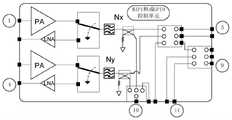
如图2B所示,该发射模组包括2路信号收发处理电路、2个通道选择开关(包括3P3T开关)和1个功率检测选择开关,信号收发处理电路包括1个PA、1个LNA、1 个收发切换开关(包括SPDT开关)、1个滤波器、1个功率耦合器。该发射模组还可以包括MIPI和/或GPIO控制单元完成PA/LNA/功率耦合器Coupler/开关切换控制。其中,As shown in Figure 2B, the transmitter module includes 2 channels of signal transceiver processing circuits, 2 channel selection switches (including 3P3T switches) and 1 power detection selection switch, and the signal transceiver processing circuit includes 1 PA, 1 LNA, 1 1 transceiver switch (including SPDT switch), 1 filter, 1 power coupler. The transmitting module may also include a MIPI and/or GPIO control unit to perform PA/LNA/Power Coupler/Switch switching control. in,
第一PA和第一LNA连接第一收发切换开关,第一收发切换开关连接第一滤波器,第一滤波器连接第一功率耦合器,第二PA和第二LNA连接第二收发切换开关,第二收发切换开关连接第二滤波器,第二滤波器连接第二功率耦合器,第一功率耦合器和第二功率耦合器连接功率检测选择开关(包括SP3T开关,其中剩余的1个T端口作为发射模组的1个外接端口,该外接端口用于将其他发射模组的n个功率耦合器通路切换到一个功率耦合通路输出),第一功率耦合器和第二功率耦合器还连接2个通道选择开关,第一通道选择开关和第二通道选择开关均包括3P3T开关,第一通道选择开关连接第二通道选择开关。The first PA and the first LNA are connected to the first transceiver switch, the first transceiver switch is connected to the first filter, the first filter is connected to the first power coupler, the second PA and the second LNA are connected to the second transceiver switch, The second transceiver switch is connected to the second filter, the second filter is connected to the second power coupler, the first power coupler and the second power coupler are connected to the power detection selection switch (including the SP3T switch, the remaining one T port As an external port of the transmitting module, the external port is used to switch the n power coupler channels of other transmitting modules to one power coupling channel output), the first power coupler and the second power coupler are also connected to 2 A channel selection switch, the first channel selection switch and the second channel selection switch both include 3P3T switches, and the first channel selection switch is connected to the second channel selection switch.
第一PA的输入端口对应发射模组的第一外接端口,第一LNA的输出端口对应发射模组的第二外接端口,第二PA的输入端口对应发射模组的第三外接端口,第二LNA的输出端口对应发射模组的第四外接端口,第一通道选择开关的第一个P端口对应发射模组的第五外接端口,第一通道选择开关的第二个P端口对应发射模组的第六外接端口,第二通道选择开关的第一个P端口对应发射模组的第七外接端口,第二通道选择开关的第二个P端口对应发射模组的第八外接端口,第二通道选择开关的第三个P端口对应发射模组的第九外接端口,功率检测选择开关的P端口对应发射模组的第十外接端口,功率检测选择开关的剩余T端口(未连接第一第二功率耦合器的T端口)对应发射模组的第十一外接端口,第一通道选择开关的第三T端口对应发射模组的第十二外接端口,第二通道选择开关的第二T端口、第三T端口分别对应发射模组的第十三外接端口、十四外接端口。The input port of the first PA corresponds to the first external port of the transmitter module, the output port of the first LNA corresponds to the second external port of the transmitter module, the input port of the second PA corresponds to the third external port of the transmitter module, the second The output port of the LNA corresponds to the fourth external port of the transmitter module, the first P port of the first channel selection switch corresponds to the fifth external port of the transmitter module, and the second P port of the first channel selection switch corresponds to the transmitter module The sixth external port of the second channel selection switch corresponds to the seventh external port of the transmitting module, the second P port of the second channel selection switch corresponds to the eighth external port of the transmitting module, and the second The third P port of the channel selection switch corresponds to the ninth external port of the transmission module, the P port of the power detection selection switch corresponds to the tenth external port of the transmission module, and the remaining T ports of the power detection selection switch (not connected to the first The T port of the two power couplers) corresponds to the eleventh external port of the transmitting module, the third T port of the first channel selection switch corresponds to the twelfth external port of the transmitting module, and the second T port of the second channel selection switch , The third T port corresponds to the thirteenth external port and the fourteenth external port of the transmitting module respectively.
其中,第一外接端口、第三外接端口用于连接射频收发器的信号发射端口,第五外接端口、第六外接端口用于连接对应的天线组的天线,第七外接端口、第八外接端口、第九外接端口用于连接接收模组或者用于连接接收模组和发射模组,第十外接端口用于连接射频收发器的功率检测PDET端口,第十一外接端口用于可选连接其他模组的功率检测通道以实现功率检测,第二外接端口、第四外接端口、第十二外接端口、第十三外接端口、第十四外接端口中的外接端口用于连接射频收发器的信号接收端口,或者,第十二外接端口、第十三外接端口、第十四外接端口中的外接端口用于连接其他发射模组的外接端口。Among them, the first external port and the third external port are used to connect the signal transmission port of the radio frequency transceiver, the fifth external port and the sixth external port are used to connect the antenna of the corresponding antenna group, the seventh external port and the eighth external port are used for connecting the antenna of the corresponding antenna group. , The ninth external port is used to connect the receiving module or the receiving module and the transmitting module, the tenth external port is used to connect the power detection PDET port of the RF transceiver, and the eleventh external port is used to connect other optional The power detection channel of the module is used to realize power detection. The second external port, the fourth external port, the twelfth external port, the thirteenth external port and the fourteenth external port are used to connect the signal of the RF transceiver. The receiving port, or the external port among the twelfth external port, the thirteenth external port, and the fourteenth external port is used to connect the external ports of other transmitting modules.
第三方面,通过如上接收模组和发射模组的定义,组成支持电子设备的5G射频架构,上述接收模组和发射模组应用于电子设备,如图3所示,所述射频系统包括射频收发器、射频处理电路和4个天线组,所述射频收发器连接所述射频处理电路,所述射频处理电路连接所述4个天线组,每个天线组包括2支天线;In the third aspect, a 5G radio frequency architecture supporting electronic equipment is formed through the above definitions of receiving modules and transmitting modules. The above receiving modules and transmitting modules are applied to electronic equipment. As shown in Figure 3, the radio frequency system includes radio frequency a transceiver, a radio frequency processing circuit and four antenna groups, the radio frequency transceiver is connected to the radio frequency processing circuit, the radio frequency processing circuit is connected to the four antenna groups, and each antenna group includes two antennas;
所述射频系统支持2个频段,所述射频处理电路包括与所述4个天线组对应的4个模组,每个模组连接1个天线组,且每个模组靠近所连接的天线组设置,所述射频处理电路还包括至少1个接收端口选择开关,每个接收端口选择开关连接射频收发器的信号接收端口,以及连接所述发射模组的外接端口,所述4个模组包括1个发射模组和3个接收模组,所述射频系统支持4天线信道探测参考信号SRS发射轮询。The radio frequency system supports two frequency bands, the radio frequency processing circuit includes four modules corresponding to the four antenna groups, each module is connected to one antenna group, and each module is close to the connected antenna group Setting, the radio frequency processing circuit further includes at least one receiving port selection switch, each receiving port selection switch is connected to the signal receiving port of the radio frequency transceiver, and is connected to the external port of the transmitting module, and the four modules include 1 transmitting module and 3 receiving modules, the radio frequency system supports 4-antenna channel sounding reference signal SRS transmission polling.
其中,所述射频系统支持2个频段和支持下行4天线同时接收功能,以及4天线信道探测参考信号SRS发射轮询功能。Wherein, the radio frequency system supports two frequency bands and supports the simultaneous reception function of
其中,所述连接关系是指耦合连接关系,如所述射频收发器具体是耦合所述射频处理电路,其他亦类似,此处不再赘述。天线的数量单位为支,1支天线表示1个天线。Wherein, the connection relationship refers to a coupling connection relationship. For example, the radio frequency transceiver is specifically coupled to the radio frequency processing circuit, and others are similar, and details are not described here. The unit of the number of antennas is branch, and one antenna means one antenna.
其中,发射模组靠近第一天线组设置,第一接收模组靠近第二天线组设置,第二接收模组靠近第三天线组设置,第三接收模组靠近第四天线组设置。Wherein, the transmitting module is disposed close to the first antenna group, the first receiving module is disposed close to the second antenna group, the second receiving module is disposed close to the third antenna group, and the third receiving module is disposed close to the fourth antenna group.
可见,本示例中,由于射频系统中的各个模组靠近对应天线组设置,且仅需要接收模组和发射模组即可构建核心处理电路,有利于提升各通道灵敏度,相比分离器件搭建,集成度更高,面积/成本/功耗更优。It can be seen that in this example, since each module in the radio frequency system is set close to the corresponding antenna group, and only the receiving module and the transmitting module are needed to construct the core processing circuit, it is beneficial to improve the sensitivity of each channel. Compared with the construction of separate components, Higher integration, better area/cost/power consumption.
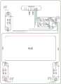
在一个可能的示例中,所述射频系统应用于电子设备,所述电子设备包括主板、电池和副板,所述主板和副板分别位于所述电池的两侧,所述接收端口选择开关的数量为 1个,所述接收端口选择开关设置于所述主板上,所述1个发射模组设置于所述主板上,且2个接收模组设置于所述主板上,另一个接收模组设置于所述副板上。In a possible example, the radio frequency system is applied to an electronic device, and the electronic device includes a main board, a battery and a sub-board, the main board and the sub-board are respectively located on two sides of the battery, and the receiving port selection switch The number is 1, the receiving port selection switch is arranged on the main board, the 1 transmitting module is arranged on the main board, and 2 receiving modules are arranged on the main board, and the other receiving module is arranged on the main board. arranged on the sub-board.
其中,所述主板具体可以位于电池上侧,副板具体可以位于电池下侧设置。The main board may be located on the upper side of the battery, and the sub-board may be located on the lower side of the battery.
在一个可能的示例中,所述射频系统应用于电子设备,所述电子设备包括主板、电池和副板,所述主板和副板分别位于所述电池的两侧,所述接收端口选择开关的数量为 2个,所述接收端口选择开关设置于所述主板上,所述1个发射模组设置于所述主板上,且1个接收模组设置于所述主板上,另两个接收模组设置于所述副板上。In a possible example, the radio frequency system is applied to an electronic device, and the electronic device includes a main board, a battery and a sub-board, the main board and the sub-board are respectively located on two sides of the battery, and the receiving port selection switch The number is 2, the receiving port selection switch is arranged on the main board, the 1 transmitting module is arranged on the main board, and the 1 receiving module is arranged on the main board, and the other two receiving modules are arranged on the main board. The group is arranged on the sub-board.
在一个可能的示例中,所述射频收发器连接所述1个发射模组,所述射频收发器的连接所述3个接收模组。In a possible example, the radio frequency transceiver is connected to the one transmitting module, and the radio frequency transceiver is connected to the three receiving modules.
在一个可能的示例中,所述发射模组包括2路信号收发处理电路、1个功率检测选择开关和2个通道选择开关,所述2路信号收发处理电路连接所述功率检测选择开关和第一通道选择开关,所述第一通道选择开关连接第二通道选择开关,所述功率检测选择开关包括SP3T开关,所述第一通道选择开关包括3P3T开关,所述第二通道选择开关包括3P3T开关;所述第一通道选择开关连接所述发射模组所对应的天线组;In a possible example, the transmitting module includes 2 channels of signal transceiving and processing circuits, 1 power detection selection switch and 2 channel selection switches, and the 2 channels of signal transceiving and processing circuits are connected to the power detection selection switch and the second channel selection switch. A channel selection switch, the first channel selection switch is connected to the second channel selection switch, the power detection selection switch includes a SP3T switch, the first channel selection switch includes a 3P3T switch, and the second channel selection switch includes a 3P3T switch ; The first channel selection switch is connected to the antenna group corresponding to the transmitting module;
每个所述接收模组包括2路信号接收通道、第一切换开关、第二切换开关,所述第一切换开关连接所述2路信号接收通道,所述2路信号接收通道连接所述第二切换开关,所述第一切换开关包括DP4T开关,所述第二切换开关包括DP3T开关,每路信号接收通道包括滤波器Filter和低噪声放大器LNA,所述LNA连接所述Filter;所述第一切换开关用于连接所述接收模组对应的天线组的天线,所述第二切换开关用于连接所述射频收发器或所述发射模组。Each of the receiving modules includes two signal receiving channels, a first switch, and a second switch. The first switch is connected to the two signal receiving channels, and the two signal receiving channels are connected to the first switch. Two switching switches, the first switching switch includes a DP4T switch, the second switching switch includes a DP3T switch, each signal receiving channel includes a filter Filter and a low noise amplifier LNA, the LNA is connected to the Filter; A switch is used to connect the antenna of the antenna group corresponding to the receiving module, and the second switch is used to connect the radio frequency transceiver or the transmitting module.
在一个可能的示例中,所述发射模组包括2路信号收发处理电路、1个功率检测选择开关和2个通道选择开关,所述2路信号收发处理电路连接所述功率检测选择开关和第一通道选择开关,所述第一通道选择开关连接第二通道选择开关,所述功率检测选择开关包括SP3T开关,所述第一通道选择开关包括DP3T开关,所述第二通道选择开关包括3P3T开关;所述第一通道选择开关连接所述发射模组所对应的天线组;In a possible example, the transmitting module includes 2 channels of signal transceiving and processing circuits, 1 power detection selection switch and 2 channel selection switches, and the 2 channels of signal transceiving and processing circuits are connected to the power detection selection switch and the second channel selection switch. A channel selection switch, the first channel selection switch is connected to the second channel selection switch, the power detection selection switch includes a SP3T switch, the first channel selection switch includes a DP3T switch, and the second channel selection switch includes a 3P3T switch ; The first channel selection switch is connected to the antenna group corresponding to the transmitting module;
每个所述接收模组包括2路信号接收通道、第一切换开关、第二切换开关,所述第一切换开关连接所述2路信号接收通道,所述2路信号接收通道连接所述第二切换开关,所述第一切换开关包括DP4T开关,所述第二切换开关包括DP3T开关,每路信号接收通道包括滤波器Filter和低噪声放大器LNA,所述LNA连接所述Filter;所述第一切换开关用于连接所述接收模组对应的天线组的天线,所述第二切换开关用于连接所述射频收发器或所述发射模组。Each of the receiving modules includes two signal receiving channels, a first switch, and a second switch. The first switch is connected to the two signal receiving channels, and the two signal receiving channels are connected to the first switch. Two switching switches, the first switching switch includes a DP4T switch, the second switching switch includes a DP3T switch, each signal receiving channel includes a filter Filter and a low noise amplifier LNA, the LNA is connected to the Filter; A switch is used to connect the antenna of the antenna group corresponding to the receiving module, and the second switch is used to connect the radio frequency transceiver or the transmitting module.
在一个可能的示例中,所述接收模组的所述第一切换开关和所述第二切换开关之间还设置有1路内置旁路通道,所述内置旁路通道用于连接所述发射模组以支持所述接收模组的信号发射功能;和/或,所述接收模组还包括1个辅助端口AUX,所述AUX连接所述第一切换开关的1个T端口,所述AUX用于连接所述发射模组以支持所述接收模组的信号发射功能;In a possible example, a built-in bypass channel is further set between the first switch and the second switch of the receiving module, and the built-in bypass channel is used to connect the transmitter module to support the signal transmission function of the receiving module; and/or, the receiving module further includes an auxiliary port AUX, the AUX is connected to a T port of the first switch, and the AUX for connecting the transmitting module to support the signal transmitting function of the receiving module;
或者,or,
所述接收模组还包括2个AUX,所述2个AUX分别连接所述第一切换开关和所述第二切换开关,且所述第一切换开关和所述第二切换开关之间用于设置外置旁路通道以支持所述接收模组的信号发射功能;The receiving module further includes 2 AUXs, the 2 AUXs are respectively connected to the first switch and the second switch, and the space between the first switch and the second switch is used for Setting up an external bypass channel to support the signal transmission function of the receiving module;
或者,or,
所述接收模组还包括3个AUX,其中第一AUX和第二AUX连接所述第一切换开关,第三AUX连接所述第二切换开关,所述第一AUX与所述第三AUX或者所述第二 AUX与所述第三AUX之间用于设置所述外置旁路电路以支持所述接收模组的信号发射功能,或者,所述第一AUX或所述第二AUX用于连接所述发射模组以支持所述接收模组的信号发射功能。The receiving module further includes 3 AUXs, wherein the first AUX and the second AUX are connected to the first switch, the third AUX is connected to the second switch, and the first AUX is connected to the third AUX or The external bypass circuit is set between the second AUX and the third AUX to support the signal transmission function of the receiving module, or the first AUX or the second AUX is used for The transmitting module is connected to support the signal transmitting function of the receiving module.
下面对本申请实施例提供的射频系统进行详细介绍。The radio frequency system provided by the embodiments of the present application is described in detail below.
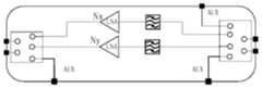
如图3A所示,该示例射频架构支持以下功能:①5G NR双频段;②不支持UL CA;③不支持DL CA;④支持4天线SRS switching;⑤NR 1T4R(1路发射4路接收)。As shown in Figure 3A, the example RF architecture supports the following functions: ① 5G NR dual-band; ② does not support UL CA; ③ does not support DL CA; ④
该5G射频架构包括射频收发器、1个发射模组、3个接收模组、1个接收端口选择开关(包括SPDT开关)、4个天线组,其中,射频收发器、发射模组、第一接收模组、第二接收模组、接收端口选择开关设置于主板上(对应附图中电池上侧2个模组),第三接收模组设置于副板上(对应附图中电池下侧2个模组),且发射模组和每个接收模组均靠近所连接的天线放置。The 5G radio frequency architecture includes a radio frequency transceiver, 1 transmitter module, 3 receiver modules, 1 receiver port selection switch (including SPDT switch), and 4 antenna groups. The receiving module, the second receiving module and the receiving port selection switch are arranged on the main board (corresponding to the two modules on the upper side of the battery in the drawing), and the third receiving module is arranged on the sub-board (corresponding to the lower side of the battery in the drawing). 2 modules), and the transmitting module and each receiving module are placed close to the connected antenna.
其中,发射模组靠近第一天线组设置,第一接收模组靠近第二天线组设置,第二接收模组靠近第三天线组组设置,第四接收模组靠近第四天线组设置。The transmitting module is arranged near the first antenna group, the first receiving module is arranged near the second antenna group, the second receiving module is arranged near the third antenna group, and the fourth receiving module is arranged near the fourth antenna group.
其中,发射模组的内部器件结构和连接关系如图2B所示,每个接收模组的内部器件结构和连接关系如图1所示。第一接收模组、第二接收模组的第一AUX(连接第一切换开关的1个AUX)连接发射模组的第九外接端口、第八外接端口以支持通过对应天线发射SRS TX信号或者自主切换天线发射信号,第三接收模组的第一AUX(连接第二切换开关的AUX)连接第二AUX(另外任意1个AUX)以支持传输SRS TX信号。The internal device structure and connection relationship of the transmitting module are shown in FIG. 2B , and the internal device structure and connection relationship of each receiving module are shown in FIG. 1 . The first AUX of the first receiving module and the second receiving module (connected to 1 AUX of the first switch) are connected to the ninth external port and the eighth external port of the transmitting module to support transmitting the SRS TX signal through the corresponding antenna or The antenna is switched autonomously to transmit signals, and the first AUX (connected to the AUX of the second switch) of the third receiving module is connected to the second AUX (any other AUX) to support the transmission of SRS TX signals.
射频收发器的第一频段的发射端口Nx TX连接发射模组的第一外接端口,第二频段的发射端口Ny TX连接发射模组的第三外接端口,射频收发器的第一频段的第一接收端口Nx RX1连接发射模组的第二外接端口,射频收发器的第一频段的第二接收端口Nx RX2连接第一接收模组的第二切换开关的第一个P端口,射频收发器的第一频段的第三接收端口Nx RX3连接第二接收模组的第二切换开关的第一个P端口,射频收发器的第二频段的第一接收端口Ny RX1连接发射模组的第四外接端口,射频收发器的第二频段的第二接收端口NyRX2连接第一接收模组的第二切换开关的第二个P端口,射频收发器的第二频段的第三接收端口Ny RX3连接第二接收模组的第二切换开关的第二个P端口,射频收发器的第一频段的第四接收端口Nx RX4和第二频段的第四接收端口Ny RX4 连接接收端口选择开关的2个T端口,接收端口选择开关的P端口连接发射模组的第十三外接端口,射频收发器的PDET端口连接发射模组的第十外接端口。The transmit port Nx TX of the first frequency band of the radio frequency transceiver is connected to the first external port of the transmit module, the transmit port Ny TX of the second frequency band is connected to the third external port of the transmit module, and the first frequency band of the radio frequency transceiver is connected to the first external port of the transmit module. The receiving port Nx RX1 is connected to the second external port of the transmitting module, the second receiving port Nx RX2 of the first frequency band of the radio frequency transceiver is connected to the first P port of the second switching switch of the first receiving module, and the The third receiving port Nx RX3 of the first frequency band is connected to the first P port of the second switch of the second receiving module, and the first receiving port Ny RX1 of the second frequency band of the radio frequency transceiver is connected to the fourth external connection of the transmitting module. Port, the second receiving port NyRX2 of the second frequency band of the radio frequency transceiver is connected to the second P port of the second switch of the first receiving module, and the third receiving port NyRX3 of the second frequency band of the radio frequency transceiver is connected to the second The second P port of the second switch of the receiving module, the fourth receiving port Nx RX4 of the first frequency band and the fourth receiving port Ny RX4 of the second frequency band of the radio frequency transceiver are connected to the two T ports of the receiving port selection switch , the P port of the receiving port selection switch is connected to the thirteenth external port of the transmitting module, and the PDET port of the radio frequency transceiver is connected to the tenth external port of the transmitting module.
第一天线组的2支天线分别连接第一发射模组的第五外接端口、第六外接端口,第二天线组的2支天线连接第一接收模组的第一切换开关的2个P端口,第三天线组的2 支天线连接第二接收模组的第一切换开关的2个P端口,第四天线组的2支天线连接第三接收模组的第一切换开关的2个P端口。The two antennas of the first antenna group are respectively connected to the fifth external port and the sixth external port of the first transmitting module, and the two antennas of the second antenna group are connected to the two P ports of the first switch of the first receiving module , the two antennas of the third antenna group are connected to the two P ports of the first switch of the second receiving module, and the two antennas of the fourth antenna group are connected to the two P ports of the first switch of the third receiving module .
包含上述射频架构的电子设备控制所述射频系统中所述射频收发器的目标频段的发射端口与目标天线组之间的发射通路导通,通过所述目标天线组中的天线发射信号。The electronic device including the above radio frequency architecture controls the transmission path between the transmit port of the target frequency band of the radio frequency transceiver in the radio frequency system and the target antenna group to conduct, and transmits signals through the antennas in the target antenna group.
具体实现中,包含上述射频架构的电子设备在执行单个频段(以Nx频段为例)的SRS4天线轮发或者自主发射切换的过程中:In the specific implementation, the electronic device including the above-mentioned radio frequency architecture performs the SRS4 antenna rotation or autonomous transmission switching of a single frequency band (taking the Nx frequency band as an example):
第一个发射周期中,电子设备控制发射模组的第一通道选择开关的第一个T端口与第一个P端口连通,发射信号,实现通过天线组的天线发射信号。In the first transmission cycle, the electronic device controls the first T port of the first channel selection switch of the transmitting module to communicate with the first P port to transmit signals, so as to transmit signals through the antennas of the antenna group.
第二个发射周期中,电子设备控制发射模组的第一通道选择开关的第一个T端口与第三个P端口连通,并控制第二通道选择开关的第一个T端口与第三个P端口连通,实现通过天线组的天线发射信号。In the second transmission cycle, the electronic device controls the first T port of the first channel selection switch of the transmission module to communicate with the third P port, and controls the first T port and the third P port of the second channel selection switch The P port is connected to transmit signals through the antennas of the antenna group.
第三个发射周期中,电子设备控制发射模组的第一通道选择开关的第一个T端口与第三个P端口连通,并控制第二通道选择开关的第一个T端口与第二个P端口连通,发射信号,实现通过天线组的天线发射信号。In the third transmission cycle, the electronic device controls the first T port of the first channel selection switch of the transmission module to communicate with the third P port, and controls the first T port of the second channel selection switch to communicate with the second The P port is connected to transmit signals, so as to transmit signals through the antennas of the antenna group.
第四个发射周期中,电子设备控制发射模组的第二通道选择开关的第一个T端口与第三个P端口连通,并控制第二通道选择开关的第一个T端口与第一个P端口连通,发射信号,实现通过天线组的天线发射信号。In the fourth transmission cycle, the electronic device controls the first T port of the second channel selection switch of the transmission module to communicate with the third P port, and controls the first T port of the second channel selection switch to communicate with the first The P port is connected to transmit signals, so as to transmit signals through the antennas of the antenna group.
如图3B所示,该示例射频架构支持以下功能:①5G NR双频段;②不支持UL CA;③不支持DL CA;④支持4天线SRS switching;⑤NR 1T4R(1路发射4路接收)。As shown in Figure 3B, the example RF architecture supports the following functions: ① 5G NR dual-band; ② does not support UL CA; ③ does not support DL CA; ④ supports 4-antenna SRS switching; ⑤ NR 1T4R (1 transmit and 4 receive).
该5G射频架构包括射频收发器、1个发射模组、3个接收模组、2个接收端口选择开关(包括SPDT开关)、4个天线组,其中,射频收发器、发射模组、第一接收模组、 2个接收端口选择开关设置于主板上(对应附图中电池上侧2个模组),第二接收模组和第三接收模组设置于副板上(对应附图中电池下侧2个模组),且发射模组和每个接收模组均靠近所连接的天线放置。The 5G radio frequency architecture includes a radio frequency transceiver, 1 transmitter module, 3 receiver modules, 2 receiver port selection switches (including SPDT switches), and 4 antenna groups. The receiving module and 2 receiving port selection switches are arranged on the main board (corresponding to 2 modules on the upper side of the battery in the accompanying drawing), and the second receiving module and the third receiving module are arranged on the sub-board (corresponding to the battery in the accompanying drawing) 2 modules on the lower side), and the transmitting module and each receiving module are placed close to the connected antenna.
其中,发射模组靠近第一天线组设置,第一接收模组靠近第二天线组设置,第二接收模组靠近第三天线组设置,第三接收模组靠近第四天线组设置。Wherein, the transmitting module is disposed close to the first antenna group, the first receiving module is disposed close to the second antenna group, the second receiving module is disposed close to the third antenna group, and the third receiving module is disposed close to the fourth antenna group.
其中,发射模组的内部器件结构和连接关系如图2B所示,每个接收模组的内部器件结构和连接关系如图1所示。第一接收模组的1个连接第一切换开关的AUX端口连接发射模组的第九外接端口以支持通过对应天线发射SRS TX信号或者自主切换天线发射信号,第二接收模组、第三接收模组的第一AUX(连接第二切换开关的AUX)连接第二AUX(另外任意1个AUX)以支持传输SRS TX信号。The internal device structure and connection relationship of the transmitting module are shown in FIG. 2B , and the internal device structure and connection relationship of each receiving module are shown in FIG. 1 . One AUX port of the first receiving module connected to the first switch is connected to the ninth external port of the transmitting module to support transmitting SRS TX signals through corresponding antennas or autonomously switching antennas to transmit signals, the second receiving module, the third receiving The first AUX of the module (the AUX connected to the second switch) is connected to the second AUX (any other AUX) to support the transmission of SRS TX signals.
射频收发器的第一频段的发射端口Nx TX连接发射模组的第一外接端口,第二频段的发射端口Ny TX连接发射模组的第三外接端口,射频收发器的第一频段的第一接收端口Nx RX1连接发射模组的第二外接端口,射频收发器的第一频段的第二接收端口Nx RX2连接第一接收模组的第二切换开关的第一个P端口,射频收发器的第二频段的第一接收端口Ny RX1连接发射模组的第四外接端口,射频收发器的第二频段的第二接收端口Ny RX2连接第一接收模组的第二切换开关的第二个P端口,射频收发器的第一频段的第三接收端口NxRX3和第二频段的第三接收端口Ny RX3连接第一接收端口选择开关的2个T端口,第一接收端口选择开关的P端口连接发射模组的第十四外接端口,射频收发器的第一频段的第四接收端口Nx RX4和第二频段的第四接收端口Ny RX4连接第二接收端口选择开关的2个T端口,第二接收端口选择开关的P端口连接发射模组的第十三外接端口,射频收发器的PDET端口连接发射模组的第十外接端口。The transmit port Nx TX of the first frequency band of the radio frequency transceiver is connected to the first external port of the transmit module, the transmit port Ny TX of the second frequency band is connected to the third external port of the transmit module, and the first frequency band of the radio frequency transceiver is connected to the first external port of the transmit module. The receiving port Nx RX1 is connected to the second external port of the transmitting module, the second receiving port Nx RX2 of the first frequency band of the radio frequency transceiver is connected to the first P port of the second switching switch of the first receiving module, and the The first receiving port Ny RX1 of the second frequency band is connected to the fourth external port of the transmitting module, and the second receiving port Ny RX2 of the second frequency band of the radio frequency transceiver is connected to the second P of the second switching switch of the first receiving module Port, the third receiving port NxRX3 of the first frequency band and the third receiving port Ny RX3 of the second frequency band of the radio frequency transceiver are connected to the 2 T ports of the first receiving port selection switch, and the P port of the first receiving port selection switch is connected to transmit The fourteenth external port of the module, the fourth receiving port Nx RX4 of the first frequency band of the radio frequency transceiver and the fourth receiving port Ny RX4 of the second frequency band are connected to the two T ports of the second receiving port selection switch, and the second receiving port The P port of the port selection switch is connected to the thirteenth external port of the transmitting module, and the PDET port of the radio frequency transceiver is connected to the tenth external port of the transmitting module.
第一天线组的2支天线分别连接第一发射模组的第五外接端口和第六外接端口,第二天线组的2支天线连接第一接收模组的第一切换开关的2个P端口,第三天线组的2 支天线连接第二接收模组的第一切换开关的2个P端口,第四天线组的2支天线连接第三接收模组的第一切换开关的2个P端口。The two antennas of the first antenna group are respectively connected to the fifth external port and the sixth external port of the first transmitting module, and the two antennas of the second antenna group are connected to the two P ports of the first switch of the first receiving module , the two antennas of the third antenna group are connected to the two P ports of the first switch of the second receiving module, and the two antennas of the fourth antenna group are connected to the two P ports of the first switch of the third receiving module .
包含上述射频架构的电子设备控制所述射频系统中所述射频收发器的目标频段的发射端口与目标天线组之间的发射通路导通,通过所述目标天线组中的天线发射信号。The electronic device including the above radio frequency architecture controls the transmission path between the transmit port of the target frequency band of the radio frequency transceiver in the radio frequency system and the target antenna group to conduct, and transmits signals through the antennas in the target antenna group.
具体实现中,包含上述射频架构的电子设备在执行单个频段(以Nx频段为例)的SRS4天线轮发或者自主发射切换的过程中:In the specific implementation, the electronic device including the above-mentioned radio frequency architecture performs the SRS4 antenna rotation or autonomous transmission switching of a single frequency band (taking the Nx frequency band as an example):
第一个发射周期中,电子设备控制发射模组的第一通道选择开关的第一个T端口与第一个P端口连通,实现通过天线组的天线发射信号。In the first transmission cycle, the electronic device controls the first T port of the first channel selection switch of the transmitting module to communicate with the first P port, so as to transmit signals through the antennas of the antenna group.
第二个发射周期中,电子设备控制发射模组的第一通道选择开关的第一个T端口与第三个P端口连通,并控制第二通道选择开关的第一个T端口与第三个P端口连通,实现通过天线组的天线发射信号。In the second transmission cycle, the electronic device controls the first T port of the first channel selection switch of the transmission module to communicate with the third P port, and controls the first T port and the third P port of the second channel selection switch The P port is connected to transmit signals through the antennas of the antenna group.
第三个发射周期中,电子设备控制发射模组的第一通道选择开关的第一个T端口与第三个P端口连通,并控制第二通道选择开关的第一个T端口与第二个P端口连通,实现通过天线组的天线发射信号。In the third transmission cycle, the electronic device controls the first T port of the first channel selection switch of the transmission module to communicate with the third P port, and controls the first T port of the second channel selection switch to communicate with the second The P port is connected to transmit signals through the antennas of the antenna group.
第四个发射周期中,电子设备控制发射模组的第一通道选择开关的第一个T端口与第三个P端口连通,并控制第二通道选择开关的第一个T端口与第一个P端口连通,实现通过天线组的天线发射信号。In the fourth transmission cycle, the electronic device controls the first T port of the first channel selection switch of the transmission module to communicate with the third P port, and controls the first T port of the second channel selection switch to communicate with the first The P port is connected to transmit signals through the antennas of the antenna group.
如图3C所示,该示例射频架构支持以下功能:①5G NR双频段;②不支持UL CA;③不支持DL CA;④支持SRS4天线轮发;⑤NR 1T4R(单频段1路发射4路接收)。As shown in Figure 3C, the example RF architecture supports the following functions: ①5G NR dual-band; ②No UL CA support; ③No DL CA support; ④Support SRS4 antenna rotation; .
该5G射频架构包括射频收发器、1个发射模组、3个接收模组、4个天线组和1个接收端口选择开关(包括SPDT开关),其中,每个天线组包括2支天线,射频收发器、发射模组、第一接收模组、第二接收模组和接收端口选择开关设置于主板上,第三接收模组设置于副板上,且发射模组和每个接收模组均靠近所连接的天线放置。The 5G radio frequency architecture includes a radio frequency transceiver, 1 transmitting module, 3 receiving modules, 4 antenna groups and a receiving port selection switch (including SPDT switch), wherein each antenna group includes 2 antennas, and the radio frequency The transceiver, the transmitting module, the first receiving module, the second receiving module and the receiving port selection switch are arranged on the main board, the third receiving module is arranged on the sub-board, and the transmitting module and each receiving module are Place close to the connected antenna.
其中,发射模组靠近第一天线组设置,第一接收模组靠近第二天线组设置,第二接收模组靠近第三天线组设置,第三接收模组靠近第四天线组设置。Wherein, the transmitting module is disposed close to the first antenna group, the first receiving module is disposed close to the second antenna group, the second receiving module is disposed close to the third antenna group, and the third receiving module is disposed close to the fourth antenna group.
其中,发射模组的内部器件结构和连接关系如图2A的发射模组所示,接收模组的内部器件和连接关系如图1的接收模组所示,第一接收模组的AUX连接发射模组的第九外接端口以支持通过对应天线发射SRS TX信号或者自主切换天线发射信号,第二接收模组的AUX连接发射模组的第八外接端口以支持通过对应天线发射SRS TX信号或者自主切换天线发射信号,第三接收模组的连接第二切换开关的AUX连接另外任意1 个AUX以支持传输SRSTX信号。Among them, the internal device structure and connection relationship of the transmitting module are shown in the transmitting module in FIG. 2A , the internal components and connection relationship of the receiving module are shown in the receiving module in FIG. 1 , and the AUX of the first receiving module is connected to transmit The ninth external port of the module supports transmitting SRS TX signals through the corresponding antenna or autonomously switches the antenna to transmit signals, and the AUX of the second receiving module is connected to the eighth external port of the transmitting module to support transmitting SRS TX signals through the corresponding antenna or autonomously. Switch the antenna to transmit signals, and the AUX of the third receiving module connected to the second switch is connected to any other AUX to support the transmission of SRSTX signals.
射频收发器的第一频段的发射端口Nx TX连接发射模组的第一外接端口,第二频段的发射端口Ny TX连接发射模组的第三外接端口,射频收发器的第一频段的第一接收端口Nx RX1连接发射模组的第二外接端口,射频收发器的第二频段的第一接收端口Ny RX1连接发射模组的第四外接端口,射频收发器的第一频段的第二接收端口Nx RX2连接第一接收模组的第二切换开关的第一个P端口,射频收发器的第二频段的第二接收端口Ny RX2连接第一接收模组的第二切换开关的第二个P端口,射频收发器的第一频段的第三接收端口NxRX3连接第二接收模组的第二切换开关的第一个P端口,射频收发器的第二频段的第三接收端口Ny RX3连接第二接收模组的第二切换开关的第二个P端口,射频收发器的第一频段的第四接收端口Nx RX4和第二频段的第四接收端口Ny RX4 连接接收端口选择开关的2个T端口,接收端口选择开关的P端口连接发射模组的第十二外接端口,射频收发器的PDET端口连接发射模组的第十外接端口。The transmit port Nx TX of the first frequency band of the radio frequency transceiver is connected to the first external port of the transmit module, the transmit port Ny TX of the second frequency band is connected to the third external port of the transmit module, and the first frequency band of the radio frequency transceiver is connected to the first external port of the transmit module. The receiving port Nx RX1 is connected to the second external port of the transmitting module, the first receiving port Ny RX1 of the second frequency band of the radio frequency transceiver is connected to the fourth external port of the transmitting module, and the second receiving port of the first frequency band of the radio frequency transceiver Nx RX2 is connected to the first P port of the second switch of the first receiving module, and the second receiving port Ny RX2 of the second frequency band of the radio frequency transceiver is connected to the second P of the second switch of the first receiving module Port, the third receiving port NxRX3 of the first frequency band of the radio frequency transceiver is connected to the first P port of the second switch of the second receiving module, and the third receiving port Ny RX3 of the second frequency band of the radio frequency transceiver is connected to the second The second P port of the second switch of the receiving module, the fourth receiving port Nx RX4 of the first frequency band and the fourth receiving port Ny RX4 of the second frequency band of the radio frequency transceiver are connected to the two T ports of the receiving port selection switch , the P port of the receiving port selection switch is connected to the twelfth external port of the transmitting module, and the PDET port of the radio frequency transceiver is connected to the tenth external port of the transmitting module.
第一天线组的2支天线分别连接发射模组的第五外接端口和第六外接端口,第二天线组的2支天线分别连接第一接收模组的第一切换开关的2个P端口,第三天线组的2 支天线分别连接第二接收模组的第一切换开关的2个P端口,第四天线组的2支天线分别连接第三接收模组的第一切换开关的2个P端口。The two antennas of the first antenna group are respectively connected to the fifth external port and the sixth external port of the transmitting module, and the two antennas of the second antenna group are respectively connected to the two P ports of the first switch of the first receiving module, The two antennas of the third antenna group are respectively connected to the two P ports of the first switch of the second receiving module, and the two antennas of the fourth antenna group are respectively connected to the two P ports of the first switch of the third receiving module port.
包含上述射频架构的电子设备控制所述射频系统中所述射频收发器的目标频段的发射端口与目标天线组之间的发射通路导通,通过所述目标天线组中的天线发射信号。The electronic device including the above radio frequency architecture controls the transmission path between the transmit port of the target frequency band of the radio frequency transceiver in the radio frequency system and the target antenna group to conduct, and transmits signals through the antennas in the target antenna group.
具体实现中,包含上述射频架构的电子设备在执行单个频段(以Nx频段为例)的SRS4天线轮发或者自主发射切换的过程中:In the specific implementation, the electronic device including the above-mentioned radio frequency architecture performs the SRS4 antenna rotation or autonomous transmission switching of a single frequency band (taking the Nx frequency band as an example):
第一个发射周期中,电子设备控制发射模组的第一通道选择开关的第一个T端口与第一个P端口连通发射信号,实现通过天线组的天线发射信号。In the first transmission cycle, the electronic device controls the first T port of the first channel selection switch of the transmitting module to communicate with the first P port to transmit signals, so as to transmit signals through the antennas of the antenna group.
第二个发射周期中,电子设备控制发射模组的第一通道选择开关的第一个P端口与第三个T端口连通,并控制第二通道选择开关的第一个T端口与本端第三个P端口连通,发射信号,实现通过天线组的天线发射信号。In the second transmission cycle, the electronic device controls the first P port of the first channel selection switch of the transmission module to communicate with the third T port, and controls the first T port of the second channel selection switch to communicate with the third port of the local end. The three P ports are connected to transmit signals, so as to transmit signals through the antennas of the antenna group.
第三个发射周期中,电子设备控制发射模组的第一通道选择开关的第一个P端口保持与第三个T端口连通,并控制第二通道选择开关的第一个T端口与本端第二个P端口连通,发射信号,实现通过天线组的天线发射信号。In the third transmission cycle, the electronic device controls the first P port of the first channel selection switch of the transmission module to keep connected with the third T port, and controls the first T port of the second channel selection switch to be connected to the local end The second P port is connected to transmit signals, so as to transmit signals through the antennas of the antenna group.
第四个发射周期中,电子设备控制发射模组的第一通道选择开关的第一个P端口保持与第三个T端口连通,并控制第二通道选择开关的第一个T端口与本端第一个P端口连通,发射信号,实现通过天线组的天线发射信号。In the fourth transmission cycle, the electronic device controls the first P port of the first channel selection switch of the transmission module to keep connected with the third T port, and controls the first T port of the second channel selection switch to connect with the local end The first P port is connected to transmit signals, so as to transmit signals through the antennas of the antenna group.
如图3D所示,该示例射频架构支持以下功能:①5G NR双频段;②不支持UL CA;③不支持DL CA;④支持SRS4天线轮发;⑤NR 1T4R(单频段1路发射4路接收)。As shown in Figure 3D, the example RF architecture supports the following functions: ① 5G NR dual-band; ② does not support UL CA; ③ does not support DL CA; ④ supports SRS4 antenna rotation; .
该5G射频架构包括射频收发器、1个发射模组、3个接收模组、4个天线组和2个接收端口选择开关(包括SPDT开关),其中,每个天线组包括2支天线,射频收发器、发射模组、第一接收模组、第一接收端口选择开关和第二接收端口选择开关设置于主板上,第二接收模组、第三接收模组设置于副板上,且发射模组和每个接收模组均靠近所连接的天线放置。The 5G radio frequency architecture includes a radio frequency transceiver, 1 transmitting module, 3 receiving modules, 4 antenna groups and 2 receiving port selection switches (including SPDT switches). The transceiver, the transmitting module, the first receiving module, the first receiving port selection switch and the second receiving port selection switch are arranged on the main board, the second receiving module and the third receiving module are arranged on the sub-board, and transmit the The module and each receiving module are placed close to the connected antenna.
其中,发射模组靠近第一天线组设置,第一接收模组靠近第二天线组设置,第二接收模组靠近第三天线组设置,第三接收模组靠近第四天线组设置。Wherein, the transmitting module is disposed close to the first antenna group, the first receiving module is disposed close to the second antenna group, the second receiving module is disposed close to the third antenna group, and the third receiving module is disposed close to the fourth antenna group.
其中,发射模组的内部器件结构和连接关系如图2A的发射模组所示,接收模组的内部器件和连接关系如图1的接收模组所示,第一接收模组的AUX连接发射模组的第九外接端口以支持通过对应天线发射SRS TX信号或者自主切换天线发射信号,第二接收模组的连接第二切换开关的AUX连接另外任意1个AUX以支持传输SRS TX信号,第三接收模组的连接第二切换开关的AUX连接另外任意1个AUX以支持传输SRS TX 信号。Among them, the internal device structure and connection relationship of the transmitting module are shown in the transmitting module in FIG. 2A , the internal components and connection relationship of the receiving module are shown in the receiving module in FIG. 1 , and the AUX of the first receiving module is connected to transmit The ninth external port of the module supports transmitting SRS TX signals through corresponding antennas or autonomously switching antennas to transmit signals. The AUX of the second receiving module connected to the second switch is connected to any other AUX to support the transmission of SRS TX signals. The AUX of the three receiving modules connected to the second switch is connected to any other AUX to support the transmission of SRS TX signals.
射频收发器的第一频段的发射端口Nx TX连接发射模组的第一外接端口,第二频段的发射端口Ny TX连接发射模组的第三外接端口,射频收发器的第一频段的第一接收端口Nx RX1连接发射模组的第二外接端口,射频收发器的第二频段的第一接收端口Ny RX1连接发射模组的第四外接端口,射频收发器的第一频段的第二接收端口Nx RX2连接第一接收模组的第二切换开关的第一个P端口,射频收发器的第二频段的第二接收端口Ny RX2连接第一接收模组的第二切换开关的第二个P端口,射频收发器的第一频段的第三接收端口NxRX3和第二频段的第三接收端口Ny RX3连接第一接收端口选择开关的2个T端口,第一接收端口选择开关的P端口连接发射模组的第十三外接端口,射频收发器的第一频段的第四接收端口Nx RX4和第二频段的第四接收端口Ny RX4连接第二接收端口选择开关的2个T端口,第二接收端口选择开关的P端口连接发射模组的第十二外接端口,射频收发器的PDET端口连接发射模组的第十外接端口。The transmit port Nx TX of the first frequency band of the radio frequency transceiver is connected to the first external port of the transmit module, the transmit port Ny TX of the second frequency band is connected to the third external port of the transmit module, and the first frequency band of the radio frequency transceiver is connected to the first external port of the transmit module. The receiving port Nx RX1 is connected to the second external port of the transmitting module, the first receiving port Ny RX1 of the second frequency band of the radio frequency transceiver is connected to the fourth external port of the transmitting module, and the second receiving port of the first frequency band of the radio frequency transceiver Nx RX2 is connected to the first P port of the second switch of the first receiving module, and the second receiving port Ny RX2 of the second frequency band of the radio frequency transceiver is connected to the second P of the second switch of the first receiving module Port, the third receiving port NxRX3 of the first frequency band and the third receiving port Ny RX3 of the second frequency band of the radio frequency transceiver are connected to the 2 T ports of the first receiving port selection switch, and the P port of the first receiving port selection switch is connected to transmit The thirteenth external port of the module, the fourth receiving port Nx RX4 of the first frequency band of the radio frequency transceiver and the fourth receiving port Ny RX4 of the second frequency band are connected to the two T ports of the second receiving port selection switch, and the second receiving port The P port of the port selection switch is connected to the twelfth external port of the transmitting module, and the PDET port of the radio frequency transceiver is connected to the tenth external port of the transmitting module.
第一天线组的2支天线分别连接发射模组的第五外接端口和第六外接端口,第二天线组的2支天线分别连接第一接收模组的第一切换开关的2个P端口,第三天线组的2 支天线分别连接第二接收模组的第一切换开关的2个P端口,第四天线组的2支天线分别连接第三接收模组的第一切换开关的2个P端口。The two antennas of the first antenna group are respectively connected to the fifth external port and the sixth external port of the transmitting module, and the two antennas of the second antenna group are respectively connected to the two P ports of the first switch of the first receiving module, The two antennas of the third antenna group are respectively connected to the two P ports of the first switch of the second receiving module, and the two antennas of the fourth antenna group are respectively connected to the two P ports of the first switch of the third receiving module port.
包含上述射频架构的电子设备控制所述射频系统中所述射频收发器的目标频段的发射端口与目标天线组之间的发射通路导通,通过所述目标天线组中的天线发射信号。The electronic device including the above radio frequency architecture controls the transmission path between the transmit port of the target frequency band of the radio frequency transceiver in the radio frequency system and the target antenna group to conduct, and transmits signals through the antennas in the target antenna group.
具体实现中,包含上述射频架构的电子设备在执行单个频段(以Nx频段为例)的SRS4天线轮发或者自主发射切换的过程中:In the specific implementation, the electronic device including the above-mentioned radio frequency architecture performs the SRS4 antenna rotation or autonomous transmission switching of a single frequency band (taking the Nx frequency band as an example):
第一个发射周期中,电子设备控制发射模组的第一通道选择开关的第一个T端口与第一个P端口连通发射信号,实现通过天线组的天线发射信号。In the first transmission cycle, the electronic device controls the first T port of the first channel selection switch of the transmitting module to communicate with the first P port to transmit signals, so as to transmit signals through the antennas of the antenna group.
第二个发射周期中,电子设备控制发射模组的第一通道选择开关的第一个P端口与第三个T端口连通,并控制第二通道选择开关的第一个T端口与本端第三个P端口连通,发射信号,实现通过天线组的天线发射信号。In the second transmission cycle, the electronic device controls the first P port of the first channel selection switch of the transmission module to communicate with the third T port, and controls the first T port of the second channel selection switch to communicate with the third port of the local end. The three P ports are connected to transmit signals, so as to transmit signals through the antennas of the antenna group.
第三个发射周期中,电子设备控制发射模组的第一通道选择开关的第一个P端口保持与第三个T端口连通,并控制第二通道选择开关的第一个T端口与本端第二个P端口连通,发射信号,实现通过天线组的天线发射信号。In the third transmission cycle, the electronic device controls the first P port of the first channel selection switch of the transmission module to keep connected with the third T port, and controls the first T port of the second channel selection switch to be connected to the local end The second P port is connected to transmit signals, so as to transmit signals through the antennas of the antenna group.
第四个发射周期中,电子设备控制发射模组的第一通道选择开关的第一个P端口保持与第三个T端口连通,并控制第二通道选择开关的第一个T端口与本端第一个P端口连通,发射信号,实现通过天线组的天线发射信号。In the fourth transmission cycle, the electronic device controls the first P port of the first channel selection switch of the transmission module to keep connected with the third T port, and controls the first T port of the second channel selection switch to connect with the local end The first P port is connected to transmit signals, so as to transmit signals through the antennas of the antenna group.
需要说明的是,本申请实施例所提供的发射模组和接收模组的外接端口有冗余,此举是为了模块统一化以便捷支持多种射频系统。It should be noted that, the external ports of the transmitting module and the receiving module provided by the embodiments of the present application are redundant, which is for the purpose of unifying the modules to conveniently support multiple radio frequency systems.
此外,本申请实施例所描述的外接端口可以是模组内部器件本体的端口,也可以是通过电线引出的独立物理端口,此处不做唯一限定。上述各类n1Pn2T(n1大于等于2,n2大于等于2)开关(包括描述的通道选择开关、功率检测选择开关、收发切换开关、第一第二切换开关、接收端口选择开关等任意开关)的内部端口的连接关系可以是全连接或者简化连接,具体可以根据需要对应设置,如3P3T开关中,第一个P端口可以仅连接第一个T端口,第二个P端口可以全连接3个T端口,全连接是指具备建立通路的内部可控电路结构,如通过开关管构建和控制等。In addition, the external port described in the embodiment of the present application may be a port of the device body inside the module, or may be an independent physical port drawn out through a wire, which is not uniquely limited here. The above-mentioned various types of n1Pn2T (n1 is greater than or equal to 2, n2 is greater than or equal to 2) switches (including the described channel selection switch, power detection selection switch, transceiver switch, first and second switch, receiving port selection switch and other arbitrary switches) internal The connection relationship of the ports can be full connection or simplified connection, which can be set according to the needs. For example, in the 3P3T switch, the first P port can only be connected to the first T port, and the second P port can be fully connected to 3 T ports. , Full connection refers to the internal controllable circuit structure with established channels, such as construction and control through switch tubes.
此外,本申请实施例所描述的射频系统中的同轴线,也可能替换成液晶聚合物材料 LCP软板等。In addition, the coaxial line in the radio frequency system described in the embodiments of the present application may also be replaced with a liquid crystal polymer material LCP flexible board or the like.
第四方面,本申请实施例提供了一种电子设备,包括射频收发器、射频处理电路和4个天线组,所述射频收发器连接所述射频处理电路,所述射频处理电路连接所述4个天线组,每个天线组包括2支天线;所述射频系统支持2个频段,所述射频处理电路包括与所述4个天线组对应的4个模组,每个模组连接1个天线组,且每个模组靠近所连接的天线组设置,所述射频处理电路还包括至少1个接收端口选择开关,每个接收端口选择开关连接射频收发器的信号接收端口,以及连接所述发射模组的外接端口,所述4 个模组包括1个发射模组和3个接收模组,所述射频系统支持4天线信道探测参考信号 SRS发射轮询;In a fourth aspect, an embodiment of the present application provides an electronic device, including a radio frequency transceiver, a radio frequency processing circuit, and four antenna groups, the radio frequency transceiver is connected to the radio frequency processing circuit, and the radio frequency processing circuit is connected to the four antenna groups. antenna groups, each antenna group includes two antennas; the radio frequency system supports two frequency bands, the radio frequency processing circuit includes four modules corresponding to the four antenna groups, and each module is connected to one antenna The radio frequency processing circuit also includes at least one receiving port selection switch, each receiving port selection switch is connected to the signal receiving port of the radio frequency transceiver, and is connected to the transmitting The external port of the module, the 4 modules include 1 transmitting module and 3 receiving modules, and the radio frequency system supports 4 antenna channel sounding reference signal SRS transmission polling;
所述电子设备至少包括以下任意一种:移动终端、基站。The electronic device includes at least any one of the following: a mobile terminal and a base station.
其中,所述射频系统支持2个频段和支持下行4天线同时接收功能,以及4天线信道探测参考信号SRS发射轮询功能。Wherein, the radio frequency system supports two frequency bands and supports the simultaneous reception function of
第五方面,本申请实施例提供了一种天线切换控制方法,应用于电子设备,所述电子设备包括射频系统,所述射频系统包括射频收发器、射频处理电路和4个天线组,所述射频收发器连接所述射频处理电路,所述射频处理电路连接所述4个天线组;如图4 所示,所述方法包括:In a fifth aspect, an embodiment of the present application provides an antenna switching control method, which is applied to an electronic device, where the electronic device includes a radio frequency system, and the radio frequency system includes a radio frequency transceiver, a radio frequency processing circuit, and four antenna groups. The radio frequency transceiver is connected to the radio frequency processing circuit, and the radio frequency processing circuit is connected to the four antenna groups; as shown in FIG. 4 , the method includes:
步骤401,所述电子设备控制所述射频系统中所述射频收发器的目标频段的发射端口与目标天线组之间的发射通路导通,通过所述目标天线组中的天线发射信号,以实现所述射频系统的4天线SRS发射轮询功能。Step 401, the electronic device controls the transmission path between the transmission port of the target frequency band of the radio frequency transceiver in the radio frequency system and the transmission path between the target antenna group to conduct, and transmits signals through the antennas in the target antenna group to achieve The 4-antenna SRS transmission polling function of the radio frequency system.
其中,目标频段包括5G NR的n79、n77、n41等判断,此处不做唯一限定。发射端口是指射频收发器的信号发射端口,目标天线组包括第一或第二或第三或第四天线组。Among them, the target frequency band includes judgments such as n79, n77, and n41 of 5G NR, which are not uniquely limited here. The transmitting port refers to the signal transmitting port of the radio frequency transceiver, and the target antenna group includes the first or second or third or fourth antenna group.
可以看出,本申请实施例中,电子设备可以实现射频系统的4天线SRS发射轮询功能,使基站通过测量手机4天线上行信号确认4路信道质量及参数,根据信道互易性再针对4路信道做下行最优化多输入多输出Massive MIMO天线阵列的波束赋形,最终使下行4x4MIMO获得最佳数据传输性能。It can be seen that, in the embodiment of the present application, the electronic device can implement the 4-antenna SRS transmission polling function of the radio frequency system, so that the base station can confirm the quality and parameters of the 4 channels by measuring the uplink signals of the 4 antennas of the mobile phone, and then target the 4 channels according to the reciprocity of the channels. The beamforming of the downlink optimized multiple-input multiple-output Massive MIMO antenna array is performed on the channel channel, and finally the downlink 4x4MIMO can obtain the best data transmission performance.
具体实现中,电子设备可以控制射频系统实现如图3-3D所描述的任意SRS4天线轮发或者自主发射切换的过程,在此不做赘述。In a specific implementation, the electronic device can control the radio frequency system to implement the process of any SRS4 antenna rotation or autonomous transmission switching as described in Figure 3-3D, which is not repeated here.
第六方面,如图5所示,本申请实施例提供了电子设备500的结构示意图,所述电子设备500包括应用处理器510、存储器520、通信接口530以及一个或多个程序521,其中,所述一个或多个程序521被存储在上述存储器520中,并且被配置由上述应用处理器510执行,所述一个或多个程序521包括用于执行以下步骤的指令;In the sixth aspect, as shown in FIG. 5 , an embodiment of the present application provides a schematic structural diagram of an
控制所述射频系统中所述射频收发器的目标频段的发射端口与目标天线组之间的发射通路导通,通过所述目标天线组中的天线发射信号,以实现所述射频系统的4天线SRS发射轮询功能。Control the transmission path between the transmission port of the target frequency band of the radio frequency transceiver in the radio frequency system and the target antenna group to conduct, and transmit signals through the antennas in the target antenna group, so as to realize the four antennas of the radio frequency system SRS transmits polling function.
可以看出,本申请实施例中,电子设备可以实现射频系统的4天线SRS发射轮询功能,使基站通过测量手机4天线上行信号确认4路信道质量及参数,根据信道互易性再针对4路信道做下行最优化多输入多输出Massive MIMO天线阵列的波束赋形,最终使下行4x4MIMO获得最佳数据传输性能。It can be seen that, in the embodiment of the present application, the electronic device can implement the 4-antenna SRS transmission polling function of the radio frequency system, so that the base station can confirm the quality and parameters of the 4 channels by measuring the uplink signals of the 4 antennas of the mobile phone, and then target the 4 channels according to the reciprocity of the channels. The beamforming of the downlink optimized multiple-input multiple-output Massive MIMO antenna array is performed on the channel channel, and finally the downlink 4x4MIMO can obtain the best data transmission performance.
第七方面,如图6所示,本申请实施例提供了一种天线切换控制装置,应用于电子设备,所述电子设备包括射频系统,所述射频系统包括,射频收发器、射频处理电路和 4个天线组,包括处理单元601和通信单元602,其中,In a seventh aspect, as shown in FIG. 6 , an embodiment of the present application provides an antenna switching control apparatus, which is applied to electronic equipment, where the electronic equipment includes a radio frequency system, and the radio frequency system includes a radio frequency transceiver, a radio frequency processing circuit, and a radio frequency system. 4 antenna groups, including the
所述处理单元601,用于通过所述通信单元602控制所述射频系统中所述射频收发器的目标频段的发射端口与目标天线组之间的发射通路导通,通过所述目标天线组中的天线发射信号,以实现所述射频系统的4天线SRS发射轮询功能。The
其中,所述天线切换控制装置还可以包括存储单元603,用于存储电子设备的程序代码和数据。所述处理单元601可以是处理器,所述通信单元602可以是触控显示屏或者收发器,存储单元603可以是存储器。Wherein, the antenna switching control apparatus may further include a
可以看出,本申请实施例中,电子设备可以实现射频系统的4天线SRS发射轮询功能,使基站通过测量手机4天线上行信号确认4路信道质量及参数,根据信道互易性再针对4路信道做下行最优化多输入多输出Massive MIMO天线阵列的波束赋形,最终使下行4x4MIMO获得最佳数据传输性能。It can be seen that, in the embodiment of the present application, the electronic device can implement the 4-antenna SRS transmission polling function of the radio frequency system, so that the base station can confirm the quality and parameters of the 4 channels by measuring the uplink signals of the 4 antennas of the mobile phone, and then target the 4 channels according to the reciprocity of the channels. The beamforming of the downlink optimized multiple-input multiple-output Massive MIMO antenna array is performed on the channel channel, and finally the downlink 4x4MIMO can obtain the best data transmission performance.
本申请实施例还提供一种计算机存储介质,其中,该计算机存储介质存储用于电子数据交换的计算机程序,该计算机程序使得计算机执行如上述方法实施例中记载的任一方法的部分或全部步骤,上述计算机包括电子设备。Embodiments of the present application further provide a computer storage medium, wherein the computer storage medium stores a computer program for electronic data exchange, and the computer program causes the computer to execute part or all of the steps of any method described in the above method embodiments , the above computer includes electronic equipment.
本申请实施例还提供一种计算机程序产品,上述计算机程序产品包括存储了计算机程序的非瞬时性计算机可读存储介质,上述计算机程序可操作来使计算机执行如上述方法实施例中记载的任一方法的部分或全部步骤。该计算机程序产品可以为一个软件安装包,上述计算机包括电子设备。Embodiments of the present application further provide a computer program product, where the computer program product includes a non-transitory computer-readable storage medium storing a computer program, and the computer program is operable to cause a computer to execute any one of the method embodiments described above. some or all of the steps of the method. The computer program product may be a software installation package, and the computer includes an electronic device.
需要说明的是,对于前述的各方法实施例,为了简单描述,故将其都表述为一系列的动作组合,但是本领域技术人员应该知悉,本申请并不受所描述的动作顺序的限制,因为依据本申请,某些步骤可以采用其他顺序或者同时进行。其次,本领域技术人员也应该知悉,说明书中所描述的实施例均属于优选实施例,所涉及的动作和模块并不一定是本申请所必须的。It should be noted that, for the sake of simple description, the foregoing method embodiments are all expressed as a series of action combinations, but those skilled in the art should know that the present application is not limited by the described action sequence. Because in accordance with the present application, certain steps may be performed in other orders or concurrently. Secondly, those skilled in the art should also know that the embodiments described in the specification are all preferred embodiments, and the actions and modules involved are not necessarily required by the present application.
在上述实施例中,对各个实施例的描述都各有侧重,某个实施例中没有详述的部分,可以参见其他实施例的相关描述。In the above-mentioned embodiments, the description of each embodiment has its own emphasis. For parts that are not described in detail in a certain embodiment, reference may be made to the relevant descriptions of other embodiments.
在本申请所提供的几个实施例中,应该理解到,所揭露的装置,可通过其它的方式实现。例如,以上所描述的装置实施例仅仅是示意性的,例如上述单元的划分,仅仅为一种逻辑功能划分,实际实现时可以有另外的划分方式,例如多个单元或组件可以结合或者可以集成到另一个系统,或一些特征可以忽略,或不执行。另一点,所显示或讨论的相互之间的耦合或直接耦合或通信连接可以是通过一些接口,装置或单元的间接耦合或通信连接,可以是电性或其它的形式。In the several embodiments provided in this application, it should be understood that the disclosed apparatus may be implemented in other manners. For example, the device embodiments described above are only illustrative. For example, the division of the above-mentioned units is only a logical function division. In actual implementation, there may be other division methods. For example, multiple units or components may be combined or integrated. to another system, or some features can be ignored, or not implemented. On the other hand, the shown or discussed mutual coupling or direct coupling or communication connection may be through some interfaces, indirect coupling or communication connection of devices or units, and may be in electrical or other forms.
上述作为分离部件说明的单元可以是或者也可以不是物理上分开的,作为单元显示的部件可以是或者也可以不是物理单元,即可以位于一个地方,或者也可以分布到多个网络单元上。可以根据实际的需要选择其中的部分或者全部单元来实现本实施例方案的目的。The above-mentioned units described as separate components may or may not be physically separated, and components displayed as units may or may not be physical units, that is, may be located in one place, or may be distributed to multiple network units. Some or all of the units may be selected according to actual needs to achieve the purpose of the solution in this embodiment.
另外,在本申请各个实施例中的各功能单元可以集成在一个处理单元中,也可以是各个单元单独物理存在,也可以两个或两个以上单元集成在一个单元中。上述集成的单元既可以采用硬件的形式实现,也可以采用软件功能单元的形式实现。In addition, each functional unit in each embodiment of the present application may be integrated into one processing unit, or each unit may exist physically alone, or two or more units may be integrated into one unit. The above-mentioned integrated units may be implemented in the form of hardware, or may be implemented in the form of software functional units.
上述集成的单元如果以软件功能单元的形式实现并作为独立的产品销售或使用时,可以存储在一个计算机可读取存储器中。基于这样的理解,本申请的技术方案本质上或者说对现有技术做出贡献的部分或者该技术方案的全部或部分可以以软件产品的形式体现出来,该计算机软件产品存储在一个存储器中,包括若干指令用以使得一台计算机设备(可为个人计算机、服务器或者网络设备等)执行本申请各个实施例上述方法的全部或部分步骤。而前述的存储器包括:U盘、只读存储器(ROM,Read-Only Memory)、随机存取存储器(RAM,Random Access Memory)、移动硬盘、磁碟或者光盘等各种可以存储程序代码的介质。The above-mentioned integrated units, if implemented in the form of software functional units and sold or used as independent products, may be stored in a computer-readable memory. Based on this understanding, the technical solution of the present application can be embodied in the form of a software product in essence, or the part that contributes to the prior art, or all or part of the technical solution, and the computer software product is stored in a memory, Several instructions are included to cause a computer device (which may be a personal computer, a server, or a network device, etc.) to execute all or part of the steps of the above-mentioned methods in the various embodiments of the present application. The aforementioned memory includes: U disk, read-only memory (ROM, Read-Only Memory), random access memory (RAM, Random Access Memory), mobile hard disk, magnetic disk or optical disk and other media that can store program codes.
本领域普通技术人员可以理解上述实施例的各种方法中的全部或部分步骤是可以通过程序来指令相关的硬件来完成,该程序可以存储于一计算机可读存储器中,存储器可以包括:闪存盘、只读存储器(英文:Read-Only Memory,简称:ROM)、随机存取器(英文:Random Access Memory,简称:RAM)、磁盘或光盘等。Those of ordinary skill in the art can understand that all or part of the steps in the various methods of the above embodiments can be completed by instructing relevant hardware through a program, and the program can be stored in a computer-readable memory, and the memory can include: a flash disk , Read-only memory (English: Read-Only Memory, referred to as: ROM), random access device (English: Random Access Memory, referred to as: RAM), magnetic disk or optical disk, etc.
以上对本申请实施例进行了详细介绍,本文中应用了具体个例对本申请的原理及实施方式进行了阐述,以上实施例的说明只是用于帮助理解本申请的方法及其核心思想;同时,对于本领域的一般技术人员,依据本申请的思想,在具体实施方式及应用范围上均会有改变之处,综上所述,本说明书内容不应理解为对本申请的限制。The embodiments of the present application have been introduced in detail above, and the principles and implementations of the present application are described in this paper by using specific examples. The descriptions of the above embodiments are only used to help understand the methods and core ideas of the present application; at the same time, for Persons of ordinary skill in the art, based on the idea of the present application, will have changes in the specific implementation manner and application scope. In summary, the contents of this specification should not be construed as limitations on the present application.
以上是本申请实施例的实施方式,应当指出,对于本技术领域的普通技术人员来说,在不脱离本申请实施例原理的前提下,还可以做出若干改进和润饰,这些改进和润饰也视为本申请的保护范围。The above is the implementation of the embodiments of the present application. It should be pointed out that for those of ordinary skill in the art, without departing from the principles of the embodiments of the present application, several improvements and modifications can also be made. These improvements and modifications are also It is regarded as the protection scope of this application.
Claims (5)
Applications Claiming Priority (2)
| Application Number | Priority Date | Filing Date | Title |
|---|---|---|---|
| CN201810811718 | 2018-07-23 | ||
| CN2018108117187 | 2018-07-23 |
Publications (2)
| Publication Number | Publication Date |
|---|---|
| CN109167611A CN109167611A (en) | 2019-01-08 |
| CN109167611Btrue CN109167611B (en) | 2020-08-21 |
Family
ID=64322639
Family Applications (21)
| Application Number | Title | Priority Date | Filing Date |
|---|---|---|---|
| CN201810826752.1AActiveCN108964677B (en) | 2018-07-23 | 2018-07-25 | Radio frequency system, antenna switching control method and related products |
| CN201810826754.0AActiveCN108988904B (en) | 2018-07-23 | 2018-07-25 | Radio frequency system, antenna switching control method and related product |
| CN201810829132.3AActiveCN108988875B (en) | 2018-07-23 | 2018-07-25 | Radio frequency system, antenna switching control method and related products |
| CN201810828093.5AActiveCN108965533B (en) | 2018-07-23 | 2018-07-25 | Radio frequency system, antenna switching control method and related product |
| CN201811006072.1AActiveCN109039370B (en) | 2018-07-23 | 2018-08-30 | Radio frequency system, antenna switching control method and related products |
| CN201811005156.3AActiveCN109150204B (en) | 2018-07-23 | 2018-08-30 | Radio frequency system, antenna switching control method and related products |
| CN201811005134.7AActiveCN109274398B (en) | 2018-07-23 | 2018-08-30 | Radio frequency system, signal receiving control method and related product |
| CN201811013432.0AActiveCN108880600B (en) | 2018-07-23 | 2018-08-31 | Radio frequency system, antenna switching control method and related products |
| CN201811012155.1APendingCN109274408A (en) | 2018-07-23 | 2018-08-31 | RF system, signal receiving control method and related products |
| CN201811013839.3AActiveCN109040371B (en) | 2018-07-23 | 2018-08-31 | RF Systems and Related Products |
| CN201811013431.6AActiveCN109167611B (en) | 2018-07-23 | 2018-08-31 | Radio frequency system and electronic equipment |
| CN201811058579.1AActiveCN109274788B (en) | 2018-07-23 | 2018-09-11 | RF Systems and Related Products |
| CN201811058582.3AActiveCN109274379B (en) | 2018-07-23 | 2018-09-11 | Radio frequency system and related product |
| CN202010910733.4AActiveCN112055105B (en) | 2018-07-23 | 2018-09-11 | Radio frequency system and related product |
| CN201811077485.9AActiveCN109004942B (en) | 2018-07-23 | 2018-09-15 | Radio frequency system and electronic equipment |
| CN201811141973.1AActiveCN109150261B (en) | 2018-07-23 | 2018-09-28 | Radio frequency system, antenna switching control method and related product |
| CN202110731146.3AActiveCN113364497B (en) | 2018-07-23 | 2018-09-28 | Radio frequency system, antenna switching control method and related products |
| CN201811143295.2AActiveCN109412657B (en) | 2018-07-23 | 2018-09-28 | Radio frequency system, antenna switching control method and related products |
| CN201811141964.2AActiveCN109245779B (en) | 2018-07-23 | 2018-09-28 | Radio frequency system, antenna switching control method and related products |
| CN201811143217.2AActiveCN109088643B (en) | 2018-07-23 | 2018-09-28 | Radio frequency system and electronic equipment |
| CN201811231562.1AActiveCN108988877B (en) | 2018-07-23 | 2018-10-22 | Radio frequency system, antenna switching control method and related products |
Family Applications Before (10)
| Application Number | Title | Priority Date | Filing Date |
|---|---|---|---|
| CN201810826752.1AActiveCN108964677B (en) | 2018-07-23 | 2018-07-25 | Radio frequency system, antenna switching control method and related products |
| CN201810826754.0AActiveCN108988904B (en) | 2018-07-23 | 2018-07-25 | Radio frequency system, antenna switching control method and related product |
| CN201810829132.3AActiveCN108988875B (en) | 2018-07-23 | 2018-07-25 | Radio frequency system, antenna switching control method and related products |
| CN201810828093.5AActiveCN108965533B (en) | 2018-07-23 | 2018-07-25 | Radio frequency system, antenna switching control method and related product |
| CN201811006072.1AActiveCN109039370B (en) | 2018-07-23 | 2018-08-30 | Radio frequency system, antenna switching control method and related products |
| CN201811005156.3AActiveCN109150204B (en) | 2018-07-23 | 2018-08-30 | Radio frequency system, antenna switching control method and related products |
| CN201811005134.7AActiveCN109274398B (en) | 2018-07-23 | 2018-08-30 | Radio frequency system, signal receiving control method and related product |
| CN201811013432.0AActiveCN108880600B (en) | 2018-07-23 | 2018-08-31 | Radio frequency system, antenna switching control method and related products |
| CN201811012155.1APendingCN109274408A (en) | 2018-07-23 | 2018-08-31 | RF system, signal receiving control method and related products |
| CN201811013839.3AActiveCN109040371B (en) | 2018-07-23 | 2018-08-31 | RF Systems and Related Products |
Family Applications After (10)
| Application Number | Title | Priority Date | Filing Date |
|---|---|---|---|
| CN201811058579.1AActiveCN109274788B (en) | 2018-07-23 | 2018-09-11 | RF Systems and Related Products |
| CN201811058582.3AActiveCN109274379B (en) | 2018-07-23 | 2018-09-11 | Radio frequency system and related product |
| CN202010910733.4AActiveCN112055105B (en) | 2018-07-23 | 2018-09-11 | Radio frequency system and related product |
| CN201811077485.9AActiveCN109004942B (en) | 2018-07-23 | 2018-09-15 | Radio frequency system and electronic equipment |
| CN201811141973.1AActiveCN109150261B (en) | 2018-07-23 | 2018-09-28 | Radio frequency system, antenna switching control method and related product |
| CN202110731146.3AActiveCN113364497B (en) | 2018-07-23 | 2018-09-28 | Radio frequency system, antenna switching control method and related products |
| CN201811143295.2AActiveCN109412657B (en) | 2018-07-23 | 2018-09-28 | Radio frequency system, antenna switching control method and related products |
| CN201811141964.2AActiveCN109245779B (en) | 2018-07-23 | 2018-09-28 | Radio frequency system, antenna switching control method and related products |
| CN201811143217.2AActiveCN109088643B (en) | 2018-07-23 | 2018-09-28 | Radio frequency system and electronic equipment |
| CN201811231562.1AActiveCN108988877B (en) | 2018-07-23 | 2018-10-22 | Radio frequency system, antenna switching control method and related products |
Country Status (4)
| Country | Link |
|---|---|
| US (1) | US11431356B2 (en) |
| EP (1) | EP3820124A4 (en) |
| CN (21) | CN108964677B (en) |
| WO (5) | WO2020019876A1 (en) |
Families Citing this family (68)
| Publication number | Priority date | Publication date | Assignee | Title |
|---|---|---|---|---|
| CN108964677B (en)* | 2018-07-23 | 2020-12-08 | Oppo广东移动通信有限公司 | Radio frequency system, antenna switching control method and related products |
| CN109634513A (en)* | 2018-12-29 | 2019-04-16 | 出门问问信息科技有限公司 | The control method and device of touch function |
| CN109951207A (en)* | 2019-03-20 | 2019-06-28 | Oppo广东移动通信有限公司 | RF systems and electronic equipment |
| CN109861734B (en)* | 2019-03-28 | 2022-04-29 | Oppo广东移动通信有限公司 | Radio frequency system, antenna switching control method, related equipment and storage medium |
| CN112054312B (en)* | 2019-06-06 | 2022-10-18 | 北京小米移动软件有限公司 | Antenna structure and electronic device |
| CN110176940B (en)* | 2019-06-14 | 2021-04-13 | Oppo广东移动通信有限公司 | Radio frequency circuit and electronic equipment |
| CN114726384A (en) | 2019-06-28 | 2022-07-08 | 华为技术有限公司 | An antenna switching circuit and electronic device |
| CN110224712B (en)* | 2019-07-08 | 2021-04-23 | Oppo广东移动通信有限公司 | Radio frequency circuit, electronic equipment and radio frequency circuit control method |
| CN110149132B (en) | 2019-07-08 | 2021-07-20 | 维沃移动通信有限公司 | A kind of switching method of transmitting antenna and terminal equipment |
| CN110535483B (en)* | 2019-07-26 | 2021-01-15 | 华为技术有限公司 | Communication modules and terminals |
| CN110830055B (en)* | 2019-10-30 | 2021-11-16 | 西安广和通无线通信有限公司 | Antenna module and antenna adapting method |
| CN111064491B (en)* | 2019-12-03 | 2021-06-15 | 青岛海信移动通信技术股份有限公司 | Mobile terminal equipment and method for receiving and transmitting signals thereof |
| WO2021134478A1 (en)* | 2019-12-31 | 2021-07-08 | 华为技术有限公司 | Communication apparatus and network device |
| CN111277298B (en)* | 2020-01-21 | 2021-11-09 | Oppo广东移动通信有限公司 | Customer premises equipment |
| CN111277299A (en)* | 2020-01-21 | 2020-06-12 | Oppo广东移动通信有限公司 | User terminal equipment |
| CN111278173B (en)* | 2020-01-21 | 2023-08-15 | Oppo广东移动通信有限公司 | Customer Pre-equipment |
| CN111245482B (en)* | 2020-01-21 | 2021-11-05 | Oppo广东移动通信有限公司 | Antenna routing method and related device |
| CN111277314B (en)* | 2020-01-21 | 2023-12-19 | Oppo广东移动通信有限公司 | Antenna routing method and related device |
| CN111294081B (en)* | 2020-01-22 | 2022-01-11 | Oppo广东移动通信有限公司 | Radio frequency system and electronic equipment |
| CN111342847B (en)* | 2020-02-13 | 2021-11-30 | 芯朴科技(上海)有限公司 | Method for adjusting output power |
| CN113746497B (en) | 2020-03-03 | 2022-07-08 | Oppo广东移动通信有限公司 | Radio frequency system and electronic equipment |
| CN111600625A (en)* | 2020-05-14 | 2020-08-28 | 锐石创芯(深圳)科技有限公司 | Radio frequency front-end circuit and radio frequency front-end device |
| WO2021238430A1 (en)* | 2020-05-26 | 2021-12-02 | Oppo广东移动通信有限公司 | Radio frequency pa mid device, radio frequency system and communication device |
| WO2021238534A1 (en)* | 2020-05-26 | 2021-12-02 | Oppo广东移动通信有限公司 | Radio frequency pa mid device, radio frequency transceiving system, and communication device |
| CN113726357A (en)* | 2020-05-26 | 2021-11-30 | Oppo广东移动通信有限公司 | Radio frequency PA Mid device, radio frequency transceiving system and communication equipment |
| CN111682885B (en)* | 2020-06-09 | 2022-10-04 | 芯朴科技(上海)有限公司 | 1T2R radio frequency circuit and wireless communication equipment |
| CN111756388B (en)* | 2020-06-28 | 2022-06-07 | 维沃移动通信有限公司 | A radio frequency circuit and electronic equipment |
| CN111800161B (en)* | 2020-06-30 | 2022-08-19 | 联想(北京)有限公司 | Electronic equipment |
| CN113972940B (en)* | 2020-07-22 | 2025-08-05 | 中兴通讯股份有限公司 | Method and terminal for transmitting detection reference signal of frequency division duplex system |
| CN111817745B (en)* | 2020-07-28 | 2022-08-05 | 惠州Tcl移动通信有限公司 | Radio frequency device and mobile terminal |
| CN112152649B (en)* | 2020-09-16 | 2022-04-12 | Oppo广东移动通信有限公司 | Radio frequency circuit, terminal device, signal transmission method, and storage medium |
| CN112152690B (en)* | 2020-09-18 | 2024-02-09 | Oppo广东移动通信有限公司 | Diversity receiving apparatus, device, method, and computer-readable storage medium |
| CN112187311B (en)* | 2020-09-27 | 2022-08-09 | Oppo广东移动通信有限公司 | Radio frequency system and communication device |
| CN112383321B (en)* | 2020-11-12 | 2022-05-13 | Oppo广东移动通信有限公司 | Radio frequency system, antenna switching control method, and customer front-end equipment |
| CN115225111B (en)* | 2020-11-27 | 2023-12-15 | Oppo广东移动通信有限公司 | Radio frequency system, antenna switching method and customer premises equipment |
| CN112564731B (en)* | 2020-12-03 | 2022-03-25 | 维沃移动通信有限公司 | Signal processing circuit, method and electronic device |
| CN117200812A (en)* | 2020-12-16 | 2023-12-08 | Oppo广东移动通信有限公司 | RF PA Mid devices, RF transceiver systems and communication equipment |
| CN114640369B (en)* | 2020-12-16 | 2023-03-24 | Oppo广东移动通信有限公司 | Radio frequency transceiving system and communication device |
| CN114640370B (en)* | 2020-12-16 | 2023-04-11 | Oppo广东移动通信有限公司 | Radio frequency transceiving system and communication device |
| CN114640359B (en)* | 2020-12-16 | 2023-08-29 | Oppo广东移动通信有限公司 | Radio frequency PA Mid device, radio frequency receiving and transmitting system and communication equipment |
| CN114759943B (en)* | 2020-12-29 | 2023-06-02 | 华为技术有限公司 | Radio frequency front-end module, method and device for controlling radio frequency front-end module |
| CN112751578B (en)* | 2021-01-06 | 2023-05-05 | Oppo广东移动通信有限公司 | RF ELNA Devices and RF Systems |
| CN112886980B (en)* | 2021-01-22 | 2022-06-10 | 维沃移动通信有限公司 | Radio frequency circuit and electronic device |
| CN114915301B (en)* | 2021-02-09 | 2023-09-05 | 北京小米移动软件有限公司 | Antenna module, terminal equipment, antenna adjustment method and device |
| CN115118297B (en)* | 2021-03-18 | 2023-11-10 | Oppo广东移动通信有限公司 | Radio frequency front end module, radio frequency receiving and transmitting system and communication equipment |
| CN115765762B (en)* | 2021-03-30 | 2024-02-13 | Oppo广东移动通信有限公司 | RF components and communications equipment |
| CN113472386A (en)* | 2021-06-30 | 2021-10-01 | 展讯通信(上海)有限公司 | Antenna module, control method and device |
| CN113765527A (en)* | 2021-07-23 | 2021-12-07 | 上海闻泰信息技术有限公司 | Frequency divider and control method thereof |
| CN113489555B (en)* | 2021-08-10 | 2023-04-18 | 上海闻泰信息技术有限公司 | Channel quality detection terminal and electronic equipment |
| CN113676213B (en)* | 2021-08-12 | 2022-07-15 | Oppo广东移动通信有限公司 | Amplifier module, radio frequency system and communication equipment |
| CN113676210B (en)* | 2021-08-12 | 2022-07-15 | Oppo广东移动通信有限公司 | Amplifier module, radio frequency system and communication equipment |
| CN113676212B (en)* | 2021-08-12 | 2022-07-15 | Oppo广东移动通信有限公司 | Amplifier module, radio frequency system and communication equipment |
| CN113676192B (en)* | 2021-08-12 | 2023-01-06 | Oppo广东移动通信有限公司 | Transmitting module, radio frequency system and communication equipment |
| CN113676193B (en)* | 2021-08-12 | 2022-11-11 | Oppo广东移动通信有限公司 | Transmitting modules, radio frequency systems and communication equipment |
| CN113676191B (en)* | 2021-08-12 | 2022-12-27 | Oppo广东移动通信有限公司 | Transmitting module, radio frequency system and communication equipment |
| CN113676207B (en)* | 2021-08-12 | 2022-12-27 | Oppo广东移动通信有限公司 | Transmitting module, radio frequency system and communication equipment |
| WO2023050421A1 (en)* | 2021-09-30 | 2023-04-06 | 华为技术有限公司 | Radio frequency front end module, radio frequency apparatus and communication device |
| CN113938152B (en)* | 2021-11-30 | 2022-12-13 | Oppo广东移动通信有限公司 | RF system and communication equipment |
| CN114244394B (en)* | 2021-11-30 | 2022-10-21 | 荣耀终端有限公司 | Radio frequency front end module, terminal equipment and control method of radio frequency front end module |
| CN114675245B (en)* | 2022-04-21 | 2024-11-15 | 中国科学院空天信息创新研究院 | A design device and method for a transceiver calibration component |
| CN115065379A (en)* | 2022-05-18 | 2022-09-16 | Oppo广东移动通信有限公司 | Radio frequency switch, radio frequency system and communication equipment |
| CN114745034B (en)* | 2022-06-13 | 2022-09-20 | 合肥龙旗智能科技有限公司 | Radio frequency module, signal receiving and transmitting method and wireless communication equipment |
| CN115037317B (en)* | 2022-06-24 | 2023-11-10 | Oppo广东移动通信有限公司 | RF LFEM devices, RF systems and communication equipment |
| CN115133950B (en)* | 2022-06-29 | 2024-03-26 | 联想(北京)有限公司 | Signal receiving and transmitting circuit, measuring method and device |
| CN115499041A (en)* | 2022-11-14 | 2022-12-20 | 深圳芯盛思技术有限公司 | Client equipment adopting phased array technology |
| CN115776304B (en)* | 2023-02-07 | 2023-05-12 | 唯捷创芯(天津)电子技术股份有限公司 | A low-loss radio frequency transceiver front-end module and electronic equipment |
| CN120498468A (en)* | 2024-07-10 | 2025-08-15 | 睿思微系统(烟台)有限公司 | A radio frequency front-end module |
| CN118764044B (en)* | 2024-09-06 | 2025-03-14 | 荣耀终端股份有限公司 | Radio frequency circuit, power control method and electronic equipment |
Citations (2)
| Publication number | Priority date | Publication date | Assignee | Title |
|---|---|---|---|---|
| CN106559277A (en)* | 2015-09-25 | 2017-04-05 | 中兴通讯股份有限公司 | The sending method and device of detection reference signal, signaling configuration method and device |
| CN206498399U (en)* | 2016-12-15 | 2017-09-15 | 江苏安其威微电子科技有限公司 | WiFi radio frequency front-end devices |
Family Cites Families (46)
| Publication number | Priority date | Publication date | Assignee | Title |
|---|---|---|---|---|
| US6819938B2 (en)* | 2001-06-26 | 2004-11-16 | Qualcomm Incorporated | System and method for power control calibration and a wireless communication device |
| CN101854198B (en)* | 2009-03-30 | 2014-01-01 | 中兴通讯股份有限公司南京分公司 | Multi-antenna transmit diversity method and device |
| CN101572939B (en)* | 2009-05-27 | 2011-12-21 | 上海华为技术有限公司 | Radio-frequency module, transceiver and method for switching control of transceiver |
| CN101800566B (en) | 2010-01-06 | 2015-09-09 | 华为终端有限公司 | A kind of radio-frequency front-end system |
| CN103026634B (en)* | 2010-05-21 | 2015-05-27 | 马维尔国际贸易有限公司 | RF front-end with integrated t/r switch |
| US8666328B2 (en)* | 2010-07-12 | 2014-03-04 | Apple Inc. | Wireless circuitry with reduced harmonic interference |
| CN202103661U (en) | 2011-07-15 | 2012-01-04 | 惠州市正源微电子有限公司 | Multi-mode multi-frequency handset radio frequency front module |
| JP6032543B2 (en)* | 2012-10-19 | 2016-11-30 | パナソニックIpマネジメント株式会社 | Antenna switching reception system and corresponding transmission system |
| US9468022B2 (en)* | 2012-12-26 | 2016-10-11 | Samsung Electronics Co., Ltd. | Method and apparatus for random access in communication system with large number of antennas |
| US20140334564A1 (en) | 2013-05-09 | 2014-11-13 | Samsung Electronics Co., Ltd | Method and system for providing low-complexity hybrid precoding in wireless communication systems |
| US9049664B2 (en)* | 2013-06-24 | 2015-06-02 | Mediatek Inc. | Wireless communications circuit for improving current consumption and RF performance |
| CN104753553B (en) | 2013-12-26 | 2019-02-12 | 中兴通讯股份有限公司 | A kind of device, mobile terminal and method improving radio frequency link transmit-receive performance |
| KR101852894B1 (en)* | 2014-02-17 | 2018-04-27 | 후아웨이 디바이스 (둥관) 컴퍼니 리미티드 | Antenna switching system and method |
| US9326171B2 (en)* | 2014-03-10 | 2016-04-26 | Qualcomm Incorporated | Enhancing data throughput using multiple receivers |
| JP6084184B2 (en)* | 2014-08-08 | 2017-02-22 | 株式会社Nttドコモ | User terminal, radio communication system, and radio communication method |
| JP6029728B2 (en)* | 2014-10-31 | 2016-11-24 | スカイワークス ソリューションズ,インコーポレイテッドSkyworks Solutions,Inc. | Diversity receiver front-end system with phase shift components |
| CN105553505B (en)* | 2015-06-29 | 2018-10-26 | 宇龙计算机通信科技(深圳)有限公司 | Carrier wave polymerize radio circuit and communication terminal |
| US10594355B2 (en)* | 2015-06-30 | 2020-03-17 | Skyworks Solutions, Inc. | Devices and methods related to radio-frequency filters on silicon-on-insulator substrate |
| US9882693B2 (en)* | 2015-09-10 | 2018-01-30 | Qualcomm, Incorporated | Short training time for MIMO systems |
| CN105827269B (en)* | 2015-09-24 | 2017-08-15 | 维沃移动通信有限公司 | A kind of radiofrequency signal R-T unit and electronic equipment |
| JP2019500776A (en)* | 2015-11-16 | 2019-01-10 | テレフオンアクチーボラゲット エルエム エリクソン(パブル) | Wireless system antenna connector device |
| US9673847B1 (en)* | 2015-11-25 | 2017-06-06 | Analog Devices, Inc. | Apparatus and methods for transceiver calibration |
| KR102468952B1 (en)* | 2016-03-07 | 2022-11-22 | 삼성전자주식회사 | Electronic apparatus and method for transceiving signals |
| US10135482B2 (en)* | 2016-03-23 | 2018-11-20 | Avago Technologies General Ip (Singapore) Pte. Ltd. | Wireless transceiver with remote frontend |
| EP3244488B1 (en)* | 2016-05-13 | 2019-09-25 | Nxp B.V. | Multi beam former |
| US10103772B2 (en)* | 2016-08-10 | 2018-10-16 | Skyworks Solutions, Inc. | Apparatus and methods for filter bypass for radio frequency front-ends |
| EP3509221B1 (en)* | 2016-08-31 | 2022-04-20 | Murata Manufacturing Co., Ltd. | Wireless communication device |
| CN106209124A (en)* | 2016-09-09 | 2016-12-07 | 桂林电子科技大学 | A kind of antenna assembly of integrated RF front-end circuit |
| CN206195770U (en)* | 2016-11-21 | 2017-05-24 | 深圳市金立通信设备有限公司 | Radio frequency transceiving device and terminal |
| US9866259B1 (en)* | 2016-11-23 | 2018-01-09 | Infineon Technologies Ag | Transmitter/receiver module for millimeter wave 5G MIMO communication systems |
| CN106792938B (en) | 2016-12-08 | 2020-09-04 | 北京邮电大学 | Mobility enhancement scheme based on dual-connection design and oriented to 5G user-centric network |
| WO2018107068A1 (en)* | 2016-12-09 | 2018-06-14 | Qualcomm Incorporated | Uplink transmit diversity and precoding |
| US10771123B2 (en)* | 2017-02-01 | 2020-09-08 | Yiming Huo | Distributed phased arrays based MIMO (DPA-MIMO) for next generation wireless user equipment hardware design and method |
| CN206472169U (en)* | 2017-02-27 | 2017-09-05 | 广东欧珀移动通信有限公司 | Board structure of circuit, antenna assembly and mobile terminal |
| CN106876874B (en)* | 2017-02-27 | 2024-02-23 | Oppo广东移动通信有限公司 | Circuit board structure and terminal |
| CN106878502B (en)* | 2017-02-27 | 2023-04-18 | Oppo广东移动通信有限公司 | Circuit board structure, antenna device and mobile terminal |
| CN206451812U (en)* | 2017-02-27 | 2017-08-29 | 广东欧珀移动通信有限公司 | Board structure of circuit and terminal |
| KR102266811B1 (en)* | 2017-06-28 | 2021-06-17 | 후아웨이 테크놀러지 컴퍼니 리미티드 | Communication device and method for assembling the communication device |
| CN107612596A (en)* | 2017-08-30 | 2018-01-19 | 努比亚技术有限公司 | A kind of multi-antenna terminal |
| CN108282182B (en)* | 2017-12-25 | 2020-08-21 | 惠州Tcl移动通信有限公司 | Radio frequency front-end circuit of antenna, circuit board and terminal thereof |
| CN108199727A (en)* | 2018-03-16 | 2018-06-22 | 广东欧珀移动通信有限公司 | Multidiameter option switch and Related product |
| CN108199729B (en)* | 2018-03-16 | 2020-09-04 | Oppo广东移动通信有限公司 | Multi-way selector switch, radio frequency system and wireless communication equipment |
| CN108199728B (en)* | 2018-03-16 | 2020-05-19 | Oppo广东移动通信有限公司 | Multiplexer switches, radio frequency systems and wireless communication equipment |
| CN108462497B (en) | 2018-03-16 | 2020-09-01 | Oppo广东移动通信有限公司 | Multi-way selector switch and related products |
| CN108199726B (en) | 2018-03-16 | 2020-08-28 | Oppo广东移动通信有限公司 | Multi-way selector switch and related products |
| CN108964677B (en)* | 2018-07-23 | 2020-12-08 | Oppo广东移动通信有限公司 | Radio frequency system, antenna switching control method and related products |
- 2018
- 2018-07-25CNCN201810826752.1Apatent/CN108964677B/enactiveActive
- 2018-07-25CNCN201810826754.0Apatent/CN108988904B/enactiveActive
- 2018-07-25CNCN201810829132.3Apatent/CN108988875B/enactiveActive
- 2018-07-25CNCN201810828093.5Apatent/CN108965533B/enactiveActive
- 2018-08-30CNCN201811006072.1Apatent/CN109039370B/enactiveActive
- 2018-08-30CNCN201811005156.3Apatent/CN109150204B/enactiveActive
- 2018-08-30CNCN201811005134.7Apatent/CN109274398B/enactiveActive
- 2018-08-31CNCN201811013432.0Apatent/CN108880600B/enactiveActive
- 2018-08-31CNCN201811012155.1Apatent/CN109274408A/enactivePending
- 2018-08-31CNCN201811013839.3Apatent/CN109040371B/enactiveActive
- 2018-08-31CNCN201811013431.6Apatent/CN109167611B/enactiveActive
- 2018-09-11CNCN201811058579.1Apatent/CN109274788B/enactiveActive
- 2018-09-11CNCN201811058582.3Apatent/CN109274379B/enactiveActive
- 2018-09-11CNCN202010910733.4Apatent/CN112055105B/enactiveActive
- 2018-09-15CNCN201811077485.9Apatent/CN109004942B/enactiveActive
- 2018-09-28CNCN201811141973.1Apatent/CN109150261B/enactiveActive
- 2018-09-28CNCN202110731146.3Apatent/CN113364497B/enactiveActive
- 2018-09-28CNCN201811143295.2Apatent/CN109412657B/enactiveActive
- 2018-09-28CNCN201811141964.2Apatent/CN109245779B/enactiveActive
- 2018-09-28CNCN201811143217.2Apatent/CN109088643B/enactiveActive
- 2018-10-22CNCN201811231562.1Apatent/CN108988877B/enactiveActive
- 2019
- 2019-06-03WOPCT/CN2019/089889patent/WO2020019876A1/ennot_activeCeased
- 2019-06-03WOPCT/CN2019/089887patent/WO2020019874A1/ennot_activeCeased
- 2019-06-03WOPCT/CN2019/089888patent/WO2020019875A1/ennot_activeCeased
- 2019-06-03EPEP19841769.3Apatent/EP3820124A4/enactivePending
- 2019-06-03WOPCT/CN2019/089890patent/WO2020019877A1/ennot_activeCeased
- 2019-06-29WOPCT/CN2019/093970patent/WO2020019942A1/ennot_activeCeased
- 2021
- 2021-01-22USUS17/156,501patent/US11431356B2/enactiveActive
Patent Citations (2)
| Publication number | Priority date | Publication date | Assignee | Title |
|---|---|---|---|---|
| CN106559277A (en)* | 2015-09-25 | 2017-04-05 | 中兴通讯股份有限公司 | The sending method and device of detection reference signal, signaling configuration method and device |
| CN206498399U (en)* | 2016-12-15 | 2017-09-15 | 江苏安其威微电子科技有限公司 | WiFi radio frequency front-end devices |
Also Published As
Similar Documents
| Publication | Publication Date | Title |
|---|---|---|
| CN109167611B (en) | Radio frequency system and electronic equipment | |
| CN109861734B (en) | Radio frequency system, antenna switching control method, related equipment and storage medium | |
| CN108988903B (en) | RF systems and electronic equipment | |
| CN108900234B (en) | Receiving module, antenna switching control method and related products |
Legal Events
| Date | Code | Title | Description |
|---|---|---|---|
| PB01 | Publication | ||
| PB01 | Publication | ||
| SE01 | Entry into force of request for substantive examination | ||
| SE01 | Entry into force of request for substantive examination | ||
| GR01 | Patent grant | ||
| GR01 | Patent grant |