CN109162686B - Method and device for predicting fire flooding front edge position - Google Patents
Method and device for predicting fire flooding front edge positionDownload PDFInfo
- Publication number
- CN109162686B CN109162686BCN201810812785.0ACN201810812785ACN109162686BCN 109162686 BCN109162686 BCN 109162686BCN 201810812785 ACN201810812785 ACN 201810812785ACN 109162686 BCN109162686 BCN 109162686B
- Authority
- CN
- China
- Prior art keywords
- well
- gas injection
- production
- production well
- oil
- Prior art date
- Legal status (The legal status is an assumption and is not a legal conclusion. Google has not performed a legal analysis and makes no representation as to the accuracy of the status listed.)
- Active
Links
Images


Classifications
- E—FIXED CONSTRUCTIONS
- E21—EARTH OR ROCK DRILLING; MINING
- E21B—EARTH OR ROCK DRILLING; OBTAINING OIL, GAS, WATER, SOLUBLE OR MELTABLE MATERIALS OR A SLURRY OF MINERALS FROM WELLS
- E21B43/00—Methods or apparatus for obtaining oil, gas, water, soluble or meltable materials or a slurry of minerals from wells
- E21B43/16—Enhanced recovery methods for obtaining hydrocarbons
- E21B43/24—Enhanced recovery methods for obtaining hydrocarbons using heat, e.g. steam injection
- E21B43/243—Combustion in situ
- E—FIXED CONSTRUCTIONS
- E21—EARTH OR ROCK DRILLING; MINING
- E21B—EARTH OR ROCK DRILLING; OBTAINING OIL, GAS, WATER, SOLUBLE OR MELTABLE MATERIALS OR A SLURRY OF MINERALS FROM WELLS
- E21B47/00—Survey of boreholes or wells
- E—FIXED CONSTRUCTIONS
- E21—EARTH OR ROCK DRILLING; MINING
- E21B—EARTH OR ROCK DRILLING; OBTAINING OIL, GAS, WATER, SOLUBLE OR MELTABLE MATERIALS OR A SLURRY OF MINERALS FROM WELLS
- E21B47/00—Survey of boreholes or wells
- E21B47/26—Storing data down-hole, e.g. in a memory or on a record carrier
- G—PHYSICS
- G06—COMPUTING OR CALCULATING; COUNTING
- G06Q—INFORMATION AND COMMUNICATION TECHNOLOGY [ICT] SPECIALLY ADAPTED FOR ADMINISTRATIVE, COMMERCIAL, FINANCIAL, MANAGERIAL OR SUPERVISORY PURPOSES; SYSTEMS OR METHODS SPECIALLY ADAPTED FOR ADMINISTRATIVE, COMMERCIAL, FINANCIAL, MANAGERIAL OR SUPERVISORY PURPOSES, NOT OTHERWISE PROVIDED FOR
- G06Q50/00—Information and communication technology [ICT] specially adapted for implementation of business processes of specific business sectors, e.g. utilities or tourism
- G06Q50/02—Agriculture; Fishing; Forestry; Mining
Landscapes
- Engineering & Computer Science (AREA)
- Life Sciences & Earth Sciences (AREA)
- Mining & Mineral Resources (AREA)
- Physics & Mathematics (AREA)
- Geology (AREA)
- Environmental & Geological Engineering (AREA)
- Fluid Mechanics (AREA)
- General Life Sciences & Earth Sciences (AREA)
- Geochemistry & Mineralogy (AREA)
- Geophysics (AREA)
- Business, Economics & Management (AREA)
- Marine Sciences & Fisheries (AREA)
- Marketing (AREA)
- Agronomy & Crop Science (AREA)
- Health & Medical Sciences (AREA)
- Economics (AREA)
- General Health & Medical Sciences (AREA)
- Human Resources & Organizations (AREA)
- Animal Husbandry (AREA)
- Primary Health Care (AREA)
- Strategic Management (AREA)
- Tourism & Hospitality (AREA)
- General Business, Economics & Management (AREA)
- General Physics & Mathematics (AREA)
- Theoretical Computer Science (AREA)
- Management, Administration, Business Operations System, And Electronic Commerce (AREA)
Abstract
Translated fromChinese
Description
Translated fromChinese技术领域technical field
本发明涉及石油开发技术领域,具体地涉及一种用于预测火驱前缘位置的方法及装置。The invention relates to the technical field of petroleum development, in particular to a method and a device for predicting the position of a fire drive front.
背景技术Background technique
火烧油层,又称火驱,是一种提高稠油油藏采收率的热采技术。其通过持续向油层注入空气并点燃油层,以热解反应过程中生成的类焦炭物为燃料,利用燃烧产生的热量提高底层原油的流动性,生成的二氧化碳和氮气形成烟道气驱,驱替原油向生产井推进。在油层稳定燃烧的过程中,燃烧带径向推进,形成火线(火线即火驱前缘位置)。Fired oil layer, also known as fire flooding, is a thermal recovery technology that enhances the recovery of heavy oil reservoirs. By continuously injecting air into the oil layer and igniting the oil layer, the coke-like substance generated during the pyrolysis reaction is used as the fuel, and the heat generated by the combustion is used to improve the fluidity of the bottom crude oil, and the generated carbon dioxide and nitrogen form a flue gas flooding. Propel crude oil to production wells. During the stable combustion of the oil layer, the combustion zone advances radially to form a line of fire (the line of fire is the position of the front of the fire drive).
由于火驱燃烧反应复杂,加上地层非均质性的影响,在注气过程中容易发生气窜,需要及时对注采参数进行调整,维持火线均匀推进。因此,确定注气井各个方向的火驱前缘的移动距离,对分析地下燃烧状态、采取合理的注气强度、及时进行生产调整,以及提高火驱开发效果均有重要的意义。Due to the complex combustion reaction of fire flooding and the influence of formation heterogeneity, gas channeling is prone to occur during the gas injection process. It is necessary to adjust the injection and production parameters in time to maintain the uniform advance of the fire line. Therefore, determining the moving distance of the fire flooding front in all directions of the gas injection well is of great significance for analyzing the underground combustion state, adopting a reasonable gas injection intensity, adjusting production in time, and improving the development effect of fire flooding.
对于采用面积井网多层火驱开发的稠油油藏,预测火驱前缘的位置主要有以下两个问题:For heavy oil reservoirs developed by multi-layer fire flooding with area well pattern, there are two main problems in predicting the location of the fire flooding front:
(1)、平面波及不均。采用面积井网开发,由于储层的平面非均质性,注气井与其控制范围内的各生产井连通性差异较大,与注气井连通性好的生产井的尾气排量高,火驱前缘沿该方向推进较快,连通性差的井的尾气排量低,火驱前缘沿该方向推进较慢。因此,在预测火驱前缘的位置之前,需要对注气井各个方向的注入量进行劈分。(1), plane wave and uneven. With area well pattern development, due to the plane heterogeneity of the reservoir, the connectivity between the gas injection well and the production wells within its control range is quite different. The edge advances faster in this direction, and the wells with poor connectivity have low tail gas displacement, and the fire-driven front advances slowly in this direction. Therefore, before predicting the position of the fire flooding front, it is necessary to split the injection amount in all directions of the gas injection well.
(2)、纵向动用不均。多层火驱主要用于薄互层稠油油藏的开发,由于纵向非均质性较强,层间差异大,采用笼统注气,物性好的油层吸气多,动用程度较高,物性差的油层吸气少,动用程度较低。并且由于薄互层状的油藏的纵向层数多,且每层厚度都比较小,因此在研究薄互层状的油藏中的每一油层中的火驱位置时难度大。(2) Uneven vertical use. Multi-layer fire flooding is mainly used for the development of thin interbedded heavy oil reservoirs. Due to the strong vertical heterogeneity and large interlayer differences, general gas injection is adopted. Oil layers with good physical properties have more suction, higher production degree, and higher physical properties. The oil layer with poor performance has less air intake and lower production degree. And because the thin interlayered reservoir has many vertical layers, and the thickness of each layer is relatively small, it is difficult to study the fire flooding position of each oil layer in the thin interlayered reservoir.
另外,本申请发明人发现,现有的基于物质平衡的火驱前缘位置的预测方法,都是针对单层均质油藏,并没有考虑多层火驱纵向动用不均的复杂情况,也没有预测多层油层中的火驱位置的技术方案。In addition, the inventors of the present application found that the existing methods for predicting the position of the fire flooding front based on material balance are all aimed at single-layer homogeneous oil reservoirs, and do not consider the complex situation of vertical uneven production of multi-layer fire flooding. There is no technical solution for predicting the location of fire flooding in multi-layered reservoirs.
发明内容SUMMARY OF THE INVENTION
本发明实施例的目的是提供一种用于预测火驱前缘位置的方法和一种用于预测火驱前缘位置的装置,用于解决上述技术问题。The purpose of the embodiments of the present invention is to provide a method for predicting the position of a fire front and a device for predicting the position of a fire front, so as to solve the above technical problems.
为了实现上述目的,本发明实施例提供一种用于预测火驱前缘位置的方法,所述方法包括:根据目标井组中的中心注气井沿各个生产井方向的分配角、目标油藏的多个油层中的每个油层的厚度、单位体积油层燃烧消耗的空气量、所述多个油层中的每个油层的吸气百分比、所述中心注气井沿所述各个生产井方向的在一定时间段内的累积注入量和所述中心注气井与所述各个生产井之间的地层空气留存率,确定所述多个油层中的每个油层的火驱前缘沿所述各个生产井方向的推进距离。In order to achieve the above object, an embodiment of the present invention provides a method for predicting the position of a fire flooding front, the method comprising: according to the distribution angle of the central gas injection well in the target well group along the direction of each production well, the distribution angle of the target oil reservoir The thickness of each oil layer in the plurality of oil layers, the amount of air consumed by the combustion of the oil layer per unit volume, the air intake percentage of each oil layer in the plurality of oil layers, the central gas injection well along the direction of each production well at a certain The cumulative injection volume in the time period and the formation air retention rate between the central gas injection well and the respective production wells determine that the fire flooding front of each oil layer in the plurality of oil layers is along the direction of the respective production wells advance distance.
可选的,所述方法通过以下公式确定所述多个油层中的某一层的火驱前缘沿所述各个生产井方向的推进距离:
可选的,通过以下步骤确定所述目标油藏中每一油层的厚度:对目标油藏进行精细油藏描述,以建立与所述目标油藏对应的地质模型;以及根据所述地质模型,确定所述目标油藏中每一油层的厚度。Optionally, the thickness of each oil layer in the target oil reservoir is determined by the following steps: performing fine reservoir description on the target oil reservoir to establish a geological model corresponding to the target oil reservoir; and according to the geological model, The thickness of each oil layer in the target reservoir is determined.
可选的,通过以下步骤确定所述单位体积油层燃烧消耗的空气量:获取目标油藏所在位置的岩心和油样;以及根据所述岩心和油样,确定单位体积油层燃烧消耗的空气量。Optionally, the amount of air consumed by the combustion of the oil layer per unit volume is determined by the following steps: obtaining a core and an oil sample where the target oil reservoir is located; and determining the amount of air consumed by the combustion of the oil layer per unit volume according to the core and the oil sample.
可选的,通过以下步骤确定所述中心注气井沿所述各个生产井方向的在一定时间段内的累积注入量:根据所述目标井组中的所述生产井的日尾气排量和各个所述生产井周围的一线注气井的日注气量,确定所述目标井组中的各个生产井与所述各个生产井周围的所述一线注气井之间的连通性;根据所述各个生产井与所述各个生产井周围的所述一线注气井之间的连通性,确定所述各个生产井的受效方向及与所述受效方向对应的受效程度;根据所述受效方向、所述受效程度和所述各个生产井在一定时间段内的总累积尾气排量,确定所述各个生产井来自所述中心注气井方向的在所述一定时间段内的累积尾气排量;以及根据所述中心注气井在所述一定时间段内的总累积注入量和所述各个生产井来自所述中心注气井方向的在所述一定时间段内的累积尾气排量,确定所述中心注气井沿所述各个生产井方向的在所述一定时间段内的累积注入量。Optionally, the cumulative injection volume of the central gas injection well along the direction of each production well within a certain period of time is determined by the following steps: the daily gas injection volume of the first-line gas injection wells around the production well, and determine the connectivity between each production well in the target well group and the first-line gas injection wells around the respective production wells; according to the respective production wells Connectivity with the first-line gas injection wells around each production well, determine the effective direction of each production well and the effective degree corresponding to the effective direction; the effectiveness degree and the total cumulative exhaust gas discharge of each production well within a certain period of time, to determine the cumulative exhaust gas discharge of each production well from the direction of the central gas injection well within the certain period of time; and The central gas injection well is determined according to the total cumulative injection volume of the central gas injection well within the certain period of time and the cumulative exhaust gas discharge of each production well from the direction of the central gas injection well within the certain period of time. The cumulative injection amount of the gas well in the certain period of time along the direction of each production well.
可选的,所述方法还包括通过以下公式确定所述目标井组中的各个生产井与所述各个生产井周围的所述一线注气井之间的连通性:
可选的,所述方法还包括通过以下公式确定井所述各个生产井来自所述各个生产井周围的一线注气井方向的在所述一定时间段内的累积尾气排量:
可选的,所述方法还包括通过以下公式确定所述中心注气井沿所述各个生产井方向的在所述一定时间段内的累积注入量:
可选的,通过以下步骤确定所述中心注气井与所述各个生产井之间的地层空气留存率:所述各个生产井来自所述中心注气井方向的在所述一定时间段内的累积尾气排量、所述中心注气井沿所述各个生产井方向的在一定时间段内的累积注入量以及氮气含量,确定所述中心注气井与所述各个生产井之间的地层空气留存率。Optionally, determine the formation air retention rate between the central gas injection well and the respective production wells through the following steps: the accumulated exhaust gas from the respective production wells in the certain period of time from the direction of the central gas injection well The displacement, the cumulative injection volume of the central gas injection well along the direction of each production well within a certain period of time, and the nitrogen content determine the formation air retention rate between the central gas injection well and each of the production wells.
可选的,所述方法还包括通过以下公式确定所述中心注气井与所述各个生产井之间的地层空气留存率:其中,wi表示中心注气井与生产井i之间的地层空气留存率、Qi0表示生产井i来自中心注气井方向的在一定时间段内的累积尾气排量、NTi表示生产井i的尾气中的氮气百分比、NA表示注气井注入的空气中的氮气百分比、Ii0表示中心注气井沿生产井i方向的在一定时间段内的累积注入量。Optionally, the method further includes determining the formation air retention rate between the central gas injection well and each production well by the following formula: Among them, wi represents the formation air retention rate between the central gas injection well and the production well i, Qi0 represents the cumulative exhaust gas discharge of the production well i from the direction of the central gas injection well in a certain period of time, NTi represents the production well i The percentage of nitrogen in the tail gas, NA represents the percentage of nitrogen in the air injected by the gas injection well, andIi0 represents the cumulative injection amount of the central gas injection well along the direction of the production well i within a certain period of time.
可选的,所述方法还包括:根据所述目标油藏的多个油层中的每个油层的火驱前缘沿所述各个生产井方向的推进距离,确定所述目标井组中的火驱前缘沿所述各个生产井方向的推进距离。Optionally, the method further includes: according to the advancing distance of the fire flooding front of each oil layer in the multiple oil layers of the target oil reservoir along the direction of each production well, determining the fire displacement in the target well group. The driving distance of the driving front in the direction of each production well.
可选的,所述方法通过以下公式确定所述目标井组中的火驱前缘沿所述各个生产井方向的推进距离:
相应的,本发明还提供一种用于预测火驱前缘位置的装置,所述装置包括:存储器和处理器,所述存储器用于存储指令,所述指令使得所述处理器能够执行根据本申请实施例所述的用于预测火驱前缘位置的方法。Correspondingly, the present invention also provides a device for predicting the position of a fire driving front, the device comprising: a memory and a processor, the memory is used for storing instructions, the instructions enable the processor to execute according to the present invention The method for predicting the position of the front edge of a fire drive described in the embodiment of the application.
相应的,本发明还提供一种机器可读存储介质,该机器可读存储介质上存储有指令,该指令用于使得机器执行本申请实施例所述的用于预测火驱前缘位置的方法。Correspondingly, the present invention also provides a machine-readable storage medium, where instructions are stored on the machine-readable storage medium, and the instructions are used to cause the machine to execute the method for predicting the position of the front edge of a fire drive described in the embodiments of the present application .
本发明实施例提供的技术方案,考虑了井网内平面波及不均和纵向动用不均的影响,通过上述技术方案,可以预测多个油层中的每个油层的火驱前缘的推进距离,能够为多层火驱生产过程中调整注采参数提供依据。并且本发明实施例提供的技术方案,还可以判断井间连通性和地下燃烧状态。The technical solution provided by the embodiment of the present invention takes into account the influence of uneven planar sweep and vertical production unevenness in the well pattern, and through the above technical solution, the advancing distance of the fire-flooding front of each oil layer in the multiple oil layers can be predicted, It can provide a basis for adjusting injection and production parameters in the production process of multi-layer fire flooding. In addition, the technical solutions provided by the embodiments of the present invention can also judge the connectivity between wells and the state of underground combustion.
本发明实施例的其它特征和优点将在随后的具体实施方式部分予以详细说明。Other features and advantages of embodiments of the present invention will be described in detail in the detailed description section that follows.
附图说明Description of drawings
附图是用来提供对本发明实施例的进一步理解,并且构成说明书的一部分,与下面的具体实施方式一起用于解释本发明实施例,但并不构成对本发明实施例的限制。在附图中:The accompanying drawings are used to provide a further understanding of the embodiments of the present invention, and constitute a part of the specification, and are used to explain the embodiments of the present invention together with the following specific embodiments, but do not constitute limitations to the embodiments of the present invention. In the attached image:
图1是本发明实施例提供的用于预测火驱前缘位置的方法流程图;1 is a flowchart of a method for predicting the position of a fire-driven leading edge provided by an embodiment of the present invention;
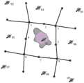
图2是本发明实施例提供的目标井组的结构示意图;2 is a schematic structural diagram of a target well group provided by an embodiment of the present invention;
图3是本发明实施例提供的油层剖面示意图;3 is a schematic cross-sectional view of an oil layer provided by an embodiment of the present invention;
图4是本发明实施例提供的生产井的受效方向及受效程度的示意图;4 is a schematic diagram of the effective direction and the effective degree of the production well provided by the embodiment of the present invention;
图5是本发明实施例提供的目标井组火驱位置平面图;5 is a plan view of the fire-flooding position of a target well group provided by an embodiment of the present invention;
图6是本发明实施例提供的用于预测火驱前缘位置的装置的结构示意图。FIG. 6 is a schematic structural diagram of an apparatus for predicting the position of a fire front edge provided by an embodiment of the present invention.
附图标记说明Description of reference numerals
1-8 生产井 01 中心注气井1-8
02-09 相邻注气井 10 存储器02-09 Adjacent gas injection well 10 Memory
20 处理器20 processors
α1 中心注气井沿生产井1方向的分配角Distribution angle of α1 central gas injection well along the direction of production well 1
α2 中心注气井沿生产井2方向的分配角Distribution angle of α2 central gas injection well along the direction of production well 2
具体实施方式Detailed ways
以下结合附图对本发明实施例的具体实施方式进行详细说明。应当理解的是,此处所描述的具体实施方式仅用于说明和解释本发明实施例,并不用于限制本发明实施例。The specific implementations of the embodiments of the present invention will be described in detail below with reference to the accompanying drawings. It should be understood that the specific implementation manners described herein are only used to illustrate and explain the embodiments of the present invention, and are not used to limit the embodiments of the present invention.
图1是本发明实施例提供的用于预测火驱前缘位置的方法流程图。如图1所示,该方法可包括如下步骤。FIG. 1 is a flowchart of a method for predicting the position of a fire driving front provided by an embodiment of the present invention. As shown in FIG. 1, the method may include the following steps.
在步骤S1中,获取根据目标井组中的中心注气井沿各个生产井方向的分配角。In step S1, the distribution angle along the direction of each production well according to the central gas injection well in the target well group is obtained.
其中,所述目标井组中的中心注气井沿各个生产井方向的分配角指的是:某一生产井与两个相邻生产井的距离的中点与中心注气井连线所构成的夹角。如图2所示,生产井1与生产井2和生产井4的中心分别与中心注气井01的连线构成了夹角α1。所述α1就表示中心注气井01沿生产井1方向的分配角。类似的,α2中心注气井01沿生产井2方向的分配角。所述分配角的大小是由中心注气井和各个生产井之间的位置关系决定的,在确定目标井组之后,中心注气井沿任一生产井方向的分配角是确定的。Wherein, the distribution angle of the central gas injection well in the target well group along the direction of each production well refers to the clip formed by the midpoint of the distance between a production well and two adjacent production wells and the connecting line of the central gas injection well horn. As shown in FIG. 2 , the lines connecting the centers of the
在步骤S2中,获取目标油藏的多个油层中的每个油层的厚度。In step S2, the thickness of each oil layer in the plurality of oil layers of the target oil reservoir is obtained.
为了解决现有技术中没有办法预测不同油层中火驱前缘的位置的问题,需要先确定目标油藏中的每一油层的厚度,这样才能预测目标油藏中的每一油层中的火驱前缘的位置。In order to solve the problem that there is no way to predict the position of the fire flooding front in different oil layers in the prior art, the thickness of each oil layer in the target oil reservoir needs to be determined first, so that the fire flooding in each oil layer in the target oil reservoir can be predicted. position of the leading edge.
具体的,本发明实施例还提供了一种确定目标油藏中每一油层的厚度的方法,其包括:对目标油藏进行精细油藏描述,以建立与目标油藏对应的地质模型,并根据所述地质模型,确定目标油藏中的每一油层的厚度。Specifically, an embodiment of the present invention also provides a method for determining the thickness of each oil layer in a target oil reservoir, which includes: performing a fine reservoir description on the target oil reservoir to establish a geological model corresponding to the target oil reservoir, and From the geological model, the thickness of each oil layer in the target reservoir is determined.
其中,油藏描述是指对油藏各种特征进行三维空间的定量描述和表征,综合多种理论和学科方法,定性和定量地描述三维空间中的油藏类型、外部几何形状,规模大小、油藏内部结构等参数。在进行石油勘探和开采时,进行油藏描述是必不可少的步骤,本发明实施例提供的技术方案仅需获取建立的地质模型中的每一油层的厚度即可。Among them, reservoir description refers to the quantitative description and characterization of various characteristics of oil reservoirs in three-dimensional space, combining a variety of theoretical and disciplinary methods to qualitatively and quantitatively describe the reservoir type, external geometry, scale, size, etc. in three-dimensional space. parameters such as the internal structure of the reservoir. When performing petroleum exploration and production, reservoir description is an essential step, and the technical solution provided by the embodiments of the present invention only needs to obtain the thickness of each oil layer in the established geological model.
在步骤S3中,获取单位体积油层燃烧消耗的空气量。In step S3, the amount of air consumed by the combustion of the oil layer per unit volume is obtained.
在本发明实施例提供的技术方案中还需要确定单位体积油层燃烧消耗的空气量。在本发明该实施例中,还提供了一种用于确定单位体积油层燃烧消耗的空气量的方法:先获取目标油藏所在位置的岩心和油样,并根据岩心和油样,确定单位体积油层燃烧消耗的空气量。In the technical solution provided by the embodiment of the present invention, it is also necessary to determine the amount of air consumed by the combustion of the oil layer per unit volume. In this embodiment of the present invention, a method for determining the amount of air consumed by the combustion of a unit volume of oil layer is also provided: first obtain the core and oil sample at the location of the target oil reservoir, and determine the unit volume according to the core and the oil sample The amount of air consumed by the combustion of the oil layer.
例如,通过取心井等设备可以钻取地下岩心和油样。工作人员通过对由所述岩心和油样构成的物理模型进行鉴定、分析和实验后,通过现有的实验手段就能测定单位体积油层燃烧消耗的空气量。For example, subsurface cores and oil samples can be drilled through equipment such as coring wells. After identifying, analyzing and experimenting on the physical model composed of the core and the oil sample, the staff can measure the air consumption per unit volume of oil layer combustion through existing experimental means.
可选的,可以通过砂子和油样确定单位体积油层燃烧消耗的空气量。Optionally, the amount of air consumed per unit volume of oil layer combustion can be determined from sand and oil samples.
在步骤S4中,获取多个油层中的每个油层的吸气百分比。In step S4, the suction percentage of each oil layer in the plurality of oil layers is obtained.
在进行火驱开发过程中,火线的推进距离会受到油层的吸气能力的影响。因此,可以通过吸气剖面测试资料,分析并确定纵向上各油层的吸气百分比。工作人员根据各个油层的吸气百分比,就能确定各个油层的吸气能力差异。In the process of fire flooding development, the advancing distance of the fire line will be affected by the suction capacity of the oil layer. Therefore, the suction percentage of each oil layer in the longitudinal direction can be analyzed and determined through the test data of the suction profile. According to the suction percentage of each oil layer, the staff can determine the difference in the suction capacity of each oil layer.
在步骤S5中,获取中心注气井沿各个生产井方向的在一定时间段内的累积注入量。In step S5, the cumulative injection amount of the central gas injection well along the direction of each production well within a certain period of time is obtained.
本发明实施例提供了一种用于确定中心注气井沿各个生产井方向的在一定时间段内的累积注入量的方法,其包括:An embodiment of the present invention provides a method for determining the cumulative injection amount of a central gas injection well along the direction of each production well within a certain period of time, comprising:
根据生产井的日尾气排量和各个生产井周围的一线注气井的日注气量,确定各个生产井与各个生产井周围的一线注气井之间的连通性;According to the daily exhaust gas displacement of the production well and the daily gas injection volume of the first-line gas injection wells around each production well, determine the connectivity between each production well and the first-line gas injection wells around each production well;
根据各个生产井与各个生产井周围的一线注气井之间的连通性,确定各个生产井的受效方向及与所述受效方向对应的受效程度;Determine the effective direction of each production well and the effective degree corresponding to the effective direction according to the connectivity between each production well and the first-line gas injection wells around each production well;
根据所述受效方向、受效程度和各个生产井在一定时间段内的总累积尾气排量,确定各个生产井来自中心注气井方向的在所述一定时间段内的累积尾气排量;以及According to the effective direction, the effective degree and the total cumulative exhaust gas discharge of each production well within a certain period of time, determine the cumulative exhaust gas discharge of each production well in the certain period of time from the direction of the central gas injection well; and
根据中心注气井在所述一定时间段内的总累积注入量和各个生产井来自中心注气井方向的在所述一定时间段内的累积尾气排量,确定中心注气井沿各个生产井方向的在所述一定时间段内的累积注入量。According to the total cumulative injection volume of the central gas injection well in the certain period of time and the cumulative exhaust gas discharge of each production well from the direction of the central gas injection well in the certain period of time, determine the position of the central gas injection well along the direction of each production well. The cumulative injection amount within the certain period of time.
可选的,还可以通过中心注气井的日注气量和生产井的日产液量(包括日产油量和日产水量)来确定的中心注气井与各个生产井之间的连通性。Optionally, the connectivity between the central gas injection well and each production well can also be determined by the daily gas injection volume of the central gas injection well and the daily liquid production volume (including daily oil production volume and daily water production volume) of the production well.
但是由于通过火驱技术开采油藏的特殊性,注气井注气量的变化引起的生产井产液量的变化会有延迟,一般都会延迟几个月,因此,不利于获取快速的响应数据。而本发明实施例提供的技术方案中,注气井的注气量对生产井的尾气排量的影响比较快,并且如果注气量与尾气排量之间的相关性好,就表示对应的注气井和生产井之间的连通性好。However, due to the particularity of oil reservoir exploitation by fire flooding technology, the change of the production well fluid production caused by the change of the gas injection volume of the gas injection well will be delayed, usually several months. Therefore, it is not conducive to obtain fast response data. In the technical solution provided by the embodiment of the present invention, the effect of the gas injection volume of the gas injection well on the exhaust gas volume of the production well is relatively fast, and if the correlation between the gas injection volume and the exhaust gas volume is good, it means that the corresponding gas injection well and Good connectivity between production wells.
相应的,本发明实施例还提供了一种用于确定目标井组中的各个生产井与各个生产井周围的一线注气井之间的连通性的公式:
qi(t)表示生产井i的日尾气排量、β0表示注采不平衡常数、βij表示生产井i与注气井j之间的连通系数,即其表示的是生产井i与注气井j之间的连通性、iij(t)表示注气井j的日注气量、n表示生产井i周围一线注气井数量(例如,如图2所示,生产井1周围一线注气井为中心注气井01、相邻注气井02、相邻注气井03和相邻注气井05,所以n为4,生产井2周围一线注气井为中心注气井01和相邻注气井03,所以n为2)。qi (t) represents the daily exhaust gas discharge of the production well i, β0 represents the injection-production imbalance constant, and βij represents the connection coefficient between the production well i and the gas injection well j, that is, it represents the production well i and the injection well j. The connectivity between gas wells j, iij (t) represents the daily gas injection volume of gas injection well j, n represents the number of first-line gas injection wells around production well i (for example, as shown in Figure 2, the first-line gas injection well around
其中,生产井i的日尾气排量qi(t)、注气井j的日注气量iij(t)和生产井i周围一线注气井数量n在进行石油开采工作过程中都是已知的。Among them, the daily exhaust gas displacement qi (t) of the production well i, the daily gas injection volume iij (t) of the gas injection well j, and the number n of the first-line gas injection wells around the production well i are all known in the process of oil exploitation. .
其中,如果要确定中心注气井与各个生产井之间的连通系数,需要将各个生产井的日尾气排量和各个生产井周围的一线注气井的日注气量代入上述用于确定连通性的公式,并通过矩阵计算确定结果。例如,如图2所示,将生产井1的日尾气排量、中心注气井01的日注气量、相邻注气井02的日注气量、相邻注气井03的日注气量和相邻注气井05的日注气量代入上述公式中,经过计算即可确定生产井1与中心注气井01之间的连通系数,同时还能够确定生产井1分别与相邻注气井02、相邻注气井03和相邻注气井05之间的连通系数。Among them, if you want to determine the connectivity coefficient between the central gas injection well and each production well, you need to substitute the daily exhaust gas displacement of each production well and the daily gas injection volume of the first-line gas injection wells around each production well into the above formula for determining connectivity , and determine the result by matrix calculation. For example, as shown in Fig. 2, the daily exhaust gas volume of
另外,本发明实施例中提到的受效方向,指注气井j到生产井i方向,与受效方向对应的受效程度,则表示生产井i排出的尾气中,来自注气井j方向的尾气所占的比例。In addition, the effective direction mentioned in the embodiment of the present invention refers to the direction from the gas injection well j to the production well i, and the effective degree corresponding to the effective direction means that in the exhaust gas discharged from the production well i, the gas from the gas injection well j direction percentage of exhaust gas.
相应的,本发明实施例还提供了一种用于确定各个生产井来自各个生产井周围的一线注气井方向的在所述一定时间段内的累积尾气排量的公式:
其中,Qij表示生产井i来自注气井j方向的在一定时间段内的累积尾气排量,βij表示生产井i与注气井j之间的连通系数、Qi表示生产井i在所述一定时间段内的总累积尾气排量、n表示生产井i周围一线注气井数量。Among them, Qij represents the cumulative exhaust gas discharge of the production welli from the direction of the gas injection well j in a certain period of time, βij represents the communication coefficient between the production well i and the gas injection well j, and Qi represents the production well i in the The total cumulative exhaust gas discharge in a certain period of time, n represents the number of first-line gas injection wells around the production well i.
其中,生产井i在所述一定时间段内的总累积尾气排量Qi和生产井i周围一线注气井数量n在进行石油开采工作过程中都是已知的。生产井i与注气井j之间的连通系数βij可以通过本发明实施例提供的方法确定,或者通过任意一种现有的技术手段确定。Wherein, the total cumulative exhaust gas discharge Qi of the production well i within the certain period of time and the number n of the first-line gas injection wells around the production well i are known during the oil exploitation process. The communication coefficient βij between the production well i and the gas injection well j may be determined by the method provided in the embodiment of the present invention, or by any existing technical means.
相应的,本发明实施例还提供了一种用于确定中心注气井沿各个生产井方向的在所述一定时间段内的累积注入量的公式:
其中,Ii0表示中心注气井沿生产井i方向的在一定时间段内的累积注入量、Qi0表示生产井i来自中心注气井方向的在一定时间段内的累积尾气排量、m表示目标井组内生产井的数量、I0表示中心注气井在所述一定时间内的总累积注入量。Among them, Ii0 represents the cumulative injection volume of the central gas injection well along the direction of the production well i in a certain period of time, Qi0 represents the cumulative exhaust gas discharge of the production well i from the direction of the central gas injection well in a certain period of time, m represents the target The number of production wells in the well group, I0 represents the total cumulative injection volume of the central gas injection well within the specified period of time.
其中,生产井i来自中心注气井方向的在一定时间段内的累积尾气排量Qi0可以由本发明实施例提供的上述用于确定各个生产井来自各个生产井周围的一线注气井方向的在所述一定时间段内的累积尾气排量的公式进行计算确定,中心注气井在所述一定时间内的总累积注入量I0在进行石油开采工作过程中是已知的。Wherein, the cumulative exhaust gas displacement Qi0 in a certain period of time from the direction of the production well i from the central gas injection well can be determined by the above-mentioned method for determining the direction of each production well from the first-line gas injection wells around each production well provided by the embodiment of the present invention. The formula for the cumulative exhaust gas discharge within a certain period of time is used to calculate and determine, and the total cumulative injection amount I0 of the central gas injection well within the certain period of time is known in the process of oil exploitation.
另外,本发明该实施例中提到的“一定时间段”可以由工作人员根据实际工作需要自行设定。In addition, the "certain time period" mentioned in this embodiment of the present invention can be set by the staff according to actual work needs.
在步骤S6中,获取中心注气井与各个生产井之间的地层空气留存率。In step S6, the formation air retention rate between the central gas injection well and each production well is obtained.
本发明实施例提供了一种通过以下步骤确定中心注气井与各个生产井之间的地层空气留存率的方法:The embodiment of the present invention provides a method for determining the formation air retention rate between the central gas injection well and each production well through the following steps:
获取各个生产井来自中心注气井方向的在一定时间段内的累积尾气排量;Obtain the cumulative exhaust gas discharge of each production well from the direction of the central gas injection well within a certain period of time;
获取中心注气井沿各个生产井方向的在一定时间段内的累积注入量;Obtain the cumulative injection volume of the central gas injection well along the direction of each production well within a certain period of time;
获取氮气含量,包括生产井排出的尾气中的氮气含量和中心注气井注入的空气中的含量;以及Obtain nitrogen content, including nitrogen content in tail gas from production wells and in air injected from central gas injection wells; and
根据上述获取的数据,确定中心注气井与各个生产井之间的地层空气留存率。According to the data obtained above, determine the formation air retention rate between the central gas injection well and each production well.
相应的,本发明实施例还提供了一种用于确定中心注气井与各个生产井之间的地层空气留存率的公式:Correspondingly, the embodiment of the present invention also provides a formula for determining the formation air retention rate between the central gas injection well and each production well:
其中,wi表示中心注气井与生产井i之间的地层空气留存率、Qi0表示生产井i来自中心注气井方向的在一定时间段内的累积尾气排量、NTi表示生产井i的尾气中的氮气百分比、NA表示注气井注入的空气中的氮气百分比、Ii0表示中心注气井沿生产井i方向的在一定时间段内的累积注入量。Among them, wi represents the formation air retention rate between the central gas injection well and the production well i, Qi0 represents the cumulative exhaust gas discharge of the production well i from the direction of the central gas injection well in a certain period of time, NTi represents the production well i The percentage of nitrogen in the tail gas, NA represents the percentage of nitrogen in the air injected by the gas injection well, andIi0 represents the cumulative injection amount of the central gas injection well along the direction of the production well i within a certain period of time.
其中,生产井i来自中心注气井方向的在一定时间段内的累积尾气排量Qi0和中心注气井沿生产井i方向的在一定时间段内的累积注入量Ii0可根据本发明实施例提供的方法进行确定,也可以通过其他方法进行确定。Wherein, the cumulative exhaust gas displacement Qi0 of the production well i from the direction of the central gas injection well within a certain period of time and the cumulative injection amount Ii0 of the central gas injection well along the direction of the production well i within a certain period of time can be according to the embodiments of the present invention The method provided is determined, and other methods can also be used to determine.
其中,在利用火驱技术开采油藏的过程中,氮气不参与燃烧反应。注气井注入的空气中的氮气含量百分比是已知的,根据注入的空气量,可以确定注入的氮气总量。根据排出的尾气总量和测定的尾气中的氮气的比例,可确定排出的尾气中的氮气总量。再根据注入的氮气总量和排出的氮气总量的差值,确定空气在地层中的留存率。Among them, in the process of exploiting oil reservoirs by fire flooding technology, nitrogen does not participate in the combustion reaction. The percentage of nitrogen content in the air injected into the gas injection well is known, and according to the amount of injected air, the total amount of injected nitrogen can be determined. According to the total amount of exhaust gas and the measured ratio of nitrogen in the exhaust gas, the total amount of nitrogen in the exhaust gas can be determined. Then, according to the difference between the total amount of nitrogen injected and the total amount of nitrogen discharged, the retention rate of air in the formation is determined.
上述步骤S1-S6的顺序不限于本发明实施例所示的顺序,可以根据实际情况按照任意的顺序获取所需的数据。The order of the above steps S1-S6 is not limited to the order shown in the embodiment of the present invention, and the required data can be acquired in any order according to the actual situation.
在步骤S7中,根据目标井组中的中心注气井沿各个生产井方向的分配角、目标油藏的多个油层中的每个油层的厚度、单位体积油层燃烧消耗的空气量、多个油层中的每个油层的吸气百分比、中心注气井沿所述各个生产井方向的在一定时间段内的累积注入量和中心注气井与各个生产井之间的地层空气留存率,确定多个油层中的每个油层的火驱前缘沿各个生产井方向的推进距离。In step S7, according to the distribution angle of the central gas injection well in the target well group along the direction of each production well, the thickness of each oil layer in the multiple oil layers of the target oil reservoir, the amount of air consumed by the combustion of the oil layer per unit volume, the multiple oil layers The air intake percentage of each oil layer in , the cumulative injection volume of the central gas injection well along the direction of each production well in a certain period of time, and the formation air retention rate between the central gas injection well and each production well, to determine multiple oil layers The advancing distance of the fire-flooding front of each oil layer in the direction of each production well.
本发明实施例还提供了一种用于确定多个油层中的每个油层的火驱前缘沿各个生产井方向的推进距离的公式:
其中,αi表示中心注气井沿生产井i方向的分配角、Rik表示第k层油层中火驱前缘沿生产井i方向的推进距离、hk表示第k层油层的厚度、As表示单位体积油层燃烧的空气量、Ii0表示中心注气井沿所述生产井i方向的在一定时间段内的累积注入量、ηk表示第k层油层的吸气百分比、Y表示氧气利用率、wi表示中心注气井与生产井i之间的地层空气留存率。where αi represents the distribution angle of the central gas injection well along the direction of production well i, Rik represents the advancing distance of the fire-flooding front in the direction of production well i in the k-th oil layer, hk represents the thickness of the k-th oil layer, Ass Represents the air volume burned in the oil layer per unit volume, Ii0 represents the cumulative injection volume of the central gas injection well along the direction of the production well i within a certain period of time, ηk represents the air intake percentage of the k-th oil layer, Y represents the oxygen utilization rate , wi represent the formation air retention rate between the central gas injection well and the production well i.
其中,上述公式中的各个参数的具体数值,都可以通过本发明实施例提供的方法确定,也可以通过其他现有的方法来确定。Wherein, the specific values of each parameter in the above formula may be determined by the method provided in the embodiment of the present invention, or may be determined by other existing methods.
可选的,为了给石油开采工作提供更多有意义的参考数据,本发明实施例提供了一种用于根据所确定的目标井组的多个油层中的每个油层的火驱前缘沿各个生产井方向的推进距离,确定目标井组中的火驱前缘沿各个生产井方向的推进距离的技术方案。Optionally, in order to provide more meaningful reference data for oil recovery work, the embodiment of the present invention provides a fire-flooding front edge for each oil layer in a plurality of oil layers in a determined target well group. The advancing distance in the direction of each production well is a technical solution for determining the advancing distance of the fire flooding front in the target well group along the direction of each production well.
相应的,本发明实施例还提供了一种用于确定目标井组中的火驱前缘沿各个生产井方向的推进距离的公式:
其中,Ri表示目标井组中的火驱前缘沿生产井i方向的推进距离、Rik表示第k层油层中火驱前缘沿生产井i方向的推进距离、hk表示第k层油层的厚度、z表示目标油藏中的油层的层数。Among them, Ri represents the advancing distance of the fire-flooding front in the target well group along the direction of production well i, Rik represents the advancing distance of the fire-flooding front in the k-th oil layer along the direction of production well i, and hk represents the k-th layer The thickness of the oil layer, z represents the number of layers of the oil layer in the target oil reservoir.
优选的,本发明实施例提供的技术方案适用于满足以下条件的目标油藏:油层边界有断层和岩性遮挡,不与水体相连;油层层数大于1,平均单层厚度大于1m;隔层连续分布;平均含油饱和度大于35%;平均孔隙度大于18%;地层原油粘度小于10000Pa·S;平均渗透率大于200mD。Preferably, the technical solutions provided in the embodiments of the present invention are suitable for target oil reservoirs that meet the following conditions: the boundary of the oil layer is blocked by faults and lithology, and is not connected to the water body; the number of oil layers is greater than 1, and the average single layer thickness is greater than 1 m; Continuous distribution; average oil saturation is greater than 35%; average porosity is greater than 18%; formation crude oil viscosity is less than 10000Pa·S; average permeability is greater than 200mD.
优选的,目标井组满足如下条件:采用井网面积开发,井距小于200m;注气井持续注入,无长期关停,注气强度大于200m3/(d·m);生产井平均氧气利用率大于85%,平均尾气二氧化碳含量大于12%。Preferably, the target well group meets the following conditions: the well pattern area is used for development, and the well spacing is less than 200m; the gas injection wells are continuously injected without long-term shutdown, and the gas injection intensity is greater than 200m3 /(d·m); the average oxygen utilization rate of the production wells More than 85%, the average exhaust carbon dioxide content is more than 12%.
为了便于理解本发明实施例提供的技术方案,现提供一具体实施例来详细解释本发明的技术方案。In order to facilitate the understanding of the technical solutions provided by the embodiments of the present invention, a specific embodiment is now provided to explain the technical solutions of the present invention in detail.
(1)选定目标油藏和目标井组:目标油藏位于中国东部某油田,为中深层薄互层状普通稠油油藏,埋深为800~1200米,目的层包括4个砂岩组20~40个油层,油层间隔层发育良好,边界封闭性较好。油藏平均孔隙度为19.3%,平均渗透率为774mD,平均含油饱和度为40%,地层原油粘度为1800Pa·S。其中,目标井组的结构示意图如图2所示,采用100m*141m正方形反九点井网开发,其油层渗透率剖面图如图3所示,纵向包含13个油层,平均单层厚度为2.3m,中心注气井01累积注入空气22.81*106m3,平均注气强度为271m3/(d·m),生产井平均氧气利用率为93%,平均尾气二氧化碳含量为18%。其中,根据图3所示的剖面图中的油层图像的灰度,对应图3右侧的标度,可以确定每一油层的对应渗透率。(1) Selecting the target oil reservoir and target well group: The target oil reservoir is located in an oil field in eastern China. It is a medium-deep thin interbedded ordinary heavy oil reservoir with a burial depth of 800-1200 meters. The target layer includes 4 sandstone groups. There are 20 to 40 oil layers, with well-developed oil interlayers and good boundary sealing. The average porosity of the reservoir is 19.3%, the average permeability is 774mD, the average oil saturation is 40%, and the formation crude oil viscosity is 1800Pa·S. Among them, the structure diagram of the target well group is shown in Figure 2. The 100m*141m square reverse nine-spot well pattern is used for development. The oil layer permeability profile is shown in Figure 3. There are 13 oil layers vertically, and the average single layer thickness is 2.3 m, the central gas injection well 01 accumulatively injects 22.81*106 m3 of air, the average gas injection intensity is 271 m3 /(d·m), the average oxygen utilization rate of the production well is 93%, and the average tail gas carbon dioxide content is 18%. Wherein, the corresponding permeability of each oil layer can be determined according to the grayscale of the oil layer image in the cross-sectional view shown in FIG. 3 , corresponding to the scale on the right side of FIG. 3 .
(2)利用开发过程中获取的岩心和油样,开展火驱室内物理模拟研究,测定燃烧单位体积油层的空气消耗量为248m3/m3。(2) Using the cores and oil samples obtained in the development process, carry out the physical simulation research in the fire flooding chamber, and determine the air consumption per unit volume of the oil layer burning to be 248m3 /m3 .
(3)根据目标井组内生产井的日尾气排量资料和目标井组及其相邻井组中注气井的日注气资料,判断目标井组内各生产井的受效方向和受效程度,采用本发明实施例提供的方法计算目标井组内生产井各受效方向的尾气贡献量。根据生产井各个受效方向的尾气贡献量和总的尾气贡献量,可以确定各个受效方向的尾气贡献率,其分析和计算结果如图4所示。其中,本发明该实施例提供的累积时间为12年。中心注气井01、注气井02、注气井03、注气井04、注气井05、注气井06、注气井07、注气井08和注气井09的累积注入量分别为:22.81×106m3、23.10×106m3、19.76×106m3、21.12×106m3、0.92×106m3、21.16×106m3、20.03×106m3、0.04×106m3和17.38×106m3。生产井1、生产井2、生产井3、生产井4、生产井5、生产井6、生产井7和生产井8的累积尾气排量分别为:6.37×10⁶m3、4.37×10⁶m3、4.78×10⁶m3、4.28×10⁶m3、7.51×10⁶m3、0.63×10⁶m3、1.86×10⁶m3和0.44×10⁶m3。经计算确定,中心注气井01对生产井1、生产井2、生产井3、生产井4、生产井5、生产井6、生产井7和生产井8的尾气贡献率分别为:74.2%、35.2%、13.4%、91.3%、82.1%、67.9%、93.3%和13.9%。另外,还可以确定注气井02、注气井03和注气井05对生产井1的尾气贡献率分别为:6.4%、14.8%和4.6%;注气井03对生产井2的尾气贡献率为64.8%;注气井03、注气井04和注气井06对生产井3的尾气贡献率为4.5%、79.1%和3%;注气井05对生产井4的尾气贡献率为8.7%;注气井06对生产井5的尾气贡献率为17.9%;注气井05、注气井06和注气井08对生产井6的尾气贡献率为1.2%、21%和9.9%;注气井08对生产井7的尾气贡献率为6.7%;注气井06、注气井08和注气井09对生产井8的尾气贡献率为23.6%、10.2%和52.3%。(3) According to the daily exhaust gas discharge data of the production wells in the target well group and the daily gas injection data of the gas injection wells in the target well group and its adjacent well groups, determine the effective direction and effectiveness of each production well in the target well group The method provided in the embodiment of the present invention is used to calculate the exhaust gas contribution of each effective direction of the production wells in the target well group. According to the exhaust gas contribution of each effective direction and the total exhaust gas contribution of the production well, the exhaust gas contribution rate of each effective direction can be determined. The analysis and calculation results are shown in Figure 4. The cumulative time provided by this embodiment of the present invention is 12 years. The cumulative injection volume of central gas injection well 01, gas injection well 02, gas injection well 03, gas injection well 04, gas injection well 05, gas injection well 06, gas injection well 07, gas injection well 08 and gas injection well 09 are: 22.81×10⁶ m3 , 23.10×10⁶ m3 , 19.76×10⁶ m3 , 21.12×10⁶ m3 , 0.92×10⁶ m3 , 21.16×10⁶ m3 , 20.03×10⁶ m3 , 0.04×10⁶ m3 and 17.38 ×10⁶ m3 . The cumulative exhaust gas discharges of
(4)根据目标井组中注气井对各生产井的尾气贡献量,判断目标井组内的井间连通性,劈分注气井沿各生产井方向的空气注入量。再根据各个生产井总的空气注入量和中心注气井的空气注入量确定中心注气井对各生产井方向的注气比例。经过分析和计算后,确定中心注气井01沿生产井1、生产井2、生产井3、生产井4、生产井5、生产井6、生产井7和生产井8方向的注气比例分别为:25.6%、8.3%、3.5%、19.5%、29.3%、2.3%、9.4%和1.9%。并且根据本发明实施例提供的技术方案,确定注入空气的平均地层空气留存率为24.5%。(4) According to the exhaust gas contribution of the gas injection wells in the target well group to each production well, the inter-well connectivity in the target well group is judged, and the air injection amount of the gas injection wells along the direction of each production well is divided. Then, according to the total air injection volume of each production well and the air injection volume of the central gas injection well, the gas injection ratio of the central gas injection well to each production well direction is determined. After analysis and calculation, it is determined that the gas injection ratios of the central gas injection well 01 along the directions of
(5)再根据吸气剖面测试资料,分析纵向上各油层的吸气能力。油层1-11的吸气百分比分别为:6%、8%、24%、12%、9%、3%、18%、0%、5%、6%和9%,由于仪器下至油层11处遇阻,油层11吸气9%为油层11-13的吸气量总和。(5) According to the test data of the suction profile, analyze the suction capacity of each oil layer in the longitudinal direction. The suction percentages for layers 1-11 are: 6%, 8%, 24%, 12%, 9%, 3%, 18%, 0%, 5%, 6%, and 9%, as the instrument goes down to the oil layer 11 In case of resistance, 9% of the suction of the oil layer 11 is the sum of the suction volume of the oil layers 11-13.
(6)采用本发明实施例提供的预测火驱前缘位置的方法,计算出各生产井方向上的火线推进距离。根据计算获得的相关数据,绘制目标井组火驱前缘位置的平面图,如图5所示。(6) Using the method for predicting the position of the fire-drive front provided in the embodiment of the present invention, the fire-line advancing distance in the direction of each production well is calculated. According to the relevant data obtained by calculation, a plan view of the position of the fire-flooding front of the target well group is drawn, as shown in Fig. 5.
其中,图5中示出的是油层1-13层的火驱前缘的平均位置。根据本发明实施例的技术方案,还可以根据实际需要计算并确定每一油层中的火驱前缘的位置,并绘制出单独的一个油层中的火驱前缘位置的平面图。Among them, Fig. 5 shows the average positions of the fire flooding fronts of oil layers 1-13. According to the technical solutions of the embodiments of the present invention, the position of the fire flooding front in each oil layer can also be calculated and determined according to actual needs, and a plan view of the position of the fire flooding front in a separate oil layer can be drawn.
本发明实施例提供的用于预测火驱前缘位置的方法,综合考虑了井网内平面波及不均和纵向动用不均的影响,通过分析目标井组内的井间连通性和各个油层的吸气能力,预测多层火驱推进位置,为多层火驱生产过程中注采参数的调控提供依据。The method for predicting the position of the fire-flooding front provided by the embodiment of the present invention comprehensively considers the influence of uneven planar sweeping and uneven vertical production in the well pattern, and analyzes the inter-well connectivity in the target well group and the relationship between each oil layer. The gas suction capacity can predict the propulsion position of multi-layer fire flooding, and provide a basis for the regulation of injection and production parameters in the production process of multi-layer fire flooding.
图6是本发明实施例提供的用于预测火驱前缘位置的装置的结构示意图。如图6所示,本发明实施例还提供了一种用于预测火驱前缘位置的装置,其包括存储器10和处理器20。其中,存储器10与处理器20相连接,存储器10用于存储指令,所述指令用于使得处理器20能够执行本发明实施例提供的任一种用于预测火驱前缘位置的方法。FIG. 6 is a schematic structural diagram of an apparatus for predicting the position of a fire front edge provided by an embodiment of the present invention. As shown in FIG. 6 , an embodiment of the present invention further provides an apparatus for predicting the position of a fire driving leading edge, which includes a memory 10 and a processor 20 . Wherein, the memory 10 is connected to the processor 20, and the memory 10 is used for storing instructions, the instructions are used for enabling the processor 20 to execute any method for predicting the position of a fire front provided in the embodiments of the present invention.
可选的,处理器20可以为通用处理器、专用处理器、常规处理器、数字信号处理器(DSP,Digital Signal Processing)、多个微处理器、与DSP核心关联的一个或多个微处理器、控制器、微控制器、专用集成电路(ASIC,Application Specific IntegratedCircuit)、现场可编程门阵列(FPGA,Field-Programmable Gate Array)电路、其他任何类型的集成电路(IC,Integrated Circuit)、嵌入式处理器等等可以实现上述功能的设备。Optionally, the processor 20 may be a general-purpose processor, a special-purpose processor, a conventional processor, a digital signal processor (DSP, Digital Signal Processing), multiple microprocessors, or one or more microprocessors associated with the DSP core device, controller, microcontroller, application specific integrated circuit (ASIC, Application Specific Integrated Circuit), field programmable gate array (FPGA, Field-Programmable Gate Array) circuit, any other type of integrated circuit (IC, Integrated Circuit), embedded A type processor or the like can realize the above-mentioned functions.
有关本发明提供的上述用于预测火驱前缘位置的装置的具体细节和益处,可参阅上述针对本发明提供的用于预测火驱前缘位置的方法的描述,于此不再赘述。For the specific details and benefits of the above-mentioned apparatus for predicting the position of a fire front edge provided by the present invention, reference may be made to the above description of the method for predicting the position of a fire front edge provided by the present invention, which will not be repeated here.
相应的,本发明实施例还提供了一种机器可读存储介质,所述机器可读存储介质上存储有指令,所述指令用于使得机器执行本发明实施例提供的用于预测火驱前缘位置的方法。Correspondingly, an embodiment of the present invention further provides a machine-readable storage medium, where instructions are stored on the machine-readable storage medium, and the instructions are used to cause a machine to execute the method for predicting a pre-fire drive provided by the embodiment of the present invention. edge location method.
以上结合附图详细描述了本发明实施例的可选实施方式,但是,本发明实施例并不限于上述实施方式中的具体细节,在本发明实施例的技术构思范围内,可以对本发明实施例的技术方案进行多种简单变型,这些简单变型均属于本发明实施例的保护范围。The optional embodiments of the embodiments of the present invention have been described in detail above with reference to the accompanying drawings. However, the embodiments of the present invention are not limited to the specific details of the above-mentioned embodiments. A variety of simple modifications are made to the technical solution of the invention, and these simple modifications all belong to the protection scope of the embodiments of the present invention.
另外需要说明的是,在上述具体实施方式中所描述的各个具体技术特征,在不矛盾的情况下,可以通过任何合适的方式进行组合。为了避免不必要的重复,本发明实施例对各种可能的组合方式不再另行说明。In addition, it should be noted that each specific technical feature described in the above-mentioned specific implementation manner may be combined in any suitable manner under the circumstance that there is no contradiction. To avoid unnecessary repetition, various possible combinations are not further described in this embodiment of the present invention.
本领域技术人员可以理解实现上述实施例方法中的全部或部分步骤是可以通过程序来指令相关的硬件来完成,该程序存储在一个存储介质中,包括若干指令用以使得单片机、芯片或处理器(processor)执行本申请各个实施例所述方法的全部或部分步骤。而前述的存储介质包括:U盘、移动硬盘、只读存储器(ROM,Read-Only Memory)、随机存取存储器(RAM,Random Access Memory)、磁碟或者光盘等各种可以存储程序代码的介质。Those skilled in the art can understand that all or part of the steps in the method of the above-mentioned embodiments can be completed by instructing the relevant hardware through a program, and the program is stored in a storage medium and includes several instructions to make a single-chip microcomputer, a chip or a processor. (processor) executes all or part of the steps of the methods described in the various embodiments of the present application. The aforementioned storage medium includes: U disk, mobile hard disk, Read-Only Memory (ROM, Read-Only Memory), Random Access Memory (RAM, Random Access Memory), magnetic disk or optical disk and other media that can store program codes .
此外,本发明实施例的各种不同的实施方式之间也可以进行任意组合,只要其不违背本发明实施例的思想,其同样应当视为本发明实施例所公开的内容。In addition, various implementations of the embodiments of the present invention may also be combined arbitrarily, as long as they do not violate the ideas of the embodiments of the present invention, they should also be regarded as the contents disclosed in the embodiments of the present invention.
Claims (11)
Translated fromChinese


Priority Applications (1)
| Application Number | Priority Date | Filing Date | Title |
|---|---|---|---|
| CN201810812785.0ACN109162686B (en) | 2018-07-23 | 2018-07-23 | Method and device for predicting fire flooding front edge position |
Applications Claiming Priority (1)
| Application Number | Priority Date | Filing Date | Title |
|---|---|---|---|
| CN201810812785.0ACN109162686B (en) | 2018-07-23 | 2018-07-23 | Method and device for predicting fire flooding front edge position |
Publications (2)
| Publication Number | Publication Date |
|---|---|
| CN109162686A CN109162686A (en) | 2019-01-08 |
| CN109162686Btrue CN109162686B (en) | 2020-01-10 |
Family
ID=64898091
Family Applications (1)
| Application Number | Title | Priority Date | Filing Date |
|---|---|---|---|
| CN201810812785.0AActiveCN109162686B (en) | 2018-07-23 | 2018-07-23 | Method and device for predicting fire flooding front edge position |
Country Status (1)
| Country | Link |
|---|---|
| CN (1) | CN109162686B (en) |
Families Citing this family (11)
| Publication number | Priority date | Publication date | Assignee | Title |
|---|---|---|---|---|
| CN111852423B (en)* | 2019-04-15 | 2022-05-10 | 中国石油天然气股份有限公司 | Fireflood leading edge determination method and device |
| CN109948108B (en)* | 2019-05-21 | 2019-08-09 | 江苏啸峰环保科技股份有限公司 | The verification method of the selection of fugitive dust discharge capacity account model, discharge capacity account and displacement data |
| CN110863806B (en)* | 2019-11-28 | 2021-07-23 | 西安石油大学 | A method for predicting the dynamic change of carbon dioxide flooding gas front |
| CN113137218B (en)* | 2020-01-16 | 2023-05-26 | 中国石油天然气股份有限公司 | Method and device for determining position of fire flooding front edge of fire flooding gas injection well |
| CN113622886A (en)* | 2020-04-22 | 2021-11-09 | 中国石油天然气股份有限公司 | Horizontal well fire flooding combustion front edge prediction method |
| CN111707325A (en)* | 2020-07-09 | 2020-09-25 | 广州能源检测研究院 | Method for calculating volume of bubbles and wall-mounted diesel oil flowing down |
| CN114060021B (en)* | 2020-08-06 | 2023-09-26 | 中国石油天然气股份有限公司 | Method and device for determining propelling distance of firing line of each oil layer of thin interbed heavy oil reservoir |
| CN113294133B (en)* | 2020-08-19 | 2023-05-26 | 中国石油天然气股份有限公司 | Method and system for determining fire flooding front edge in fire flooding well pattern |
| CN112502680A (en)* | 2020-11-19 | 2021-03-16 | 中国石油天然气股份有限公司 | Method for judging fireflood combustion state |
| CN115370336B (en)* | 2021-05-21 | 2024-07-02 | 中国石油天然气股份有限公司 | Combustion state analysis method for fireflood well group |
| CN115726751B (en)* | 2021-09-02 | 2024-11-08 | 中国石油天然气股份有限公司 | Method for judging combustion direction and state of fireflood oil reservoir |
Family Cites Families (5)
| Publication number | Priority date | Publication date | Assignee | Title |
|---|---|---|---|---|
| AU2002360301B2 (en)* | 2001-10-24 | 2007-11-29 | Shell Internationale Research Maatschappij B.V. | In situ thermal processing and upgrading of produced hydrocarbons |
| CN102877835B (en)* | 2012-10-10 | 2015-11-18 | 中国石油天然气股份有限公司 | Well temperature prediction method for horizontal production well in fireflooding process |
| CN103670356A (en)* | 2013-11-26 | 2014-03-26 | 里群 | Temperature-variable tracer composite for combustion in situ, distribution map of temperature fields of combustion in situ, production method of distribution map and development method of combustion in situ |
| CN104181602A (en)* | 2014-08-22 | 2014-12-03 | 尤尼斯油气技术(中国)有限公司 | Microseism monitoring operation method for combustion zone of in-situ combustion |
| CN106646591B (en)* | 2017-01-17 | 2019-06-21 | 克拉玛依市海晟达石油科技有限公司 | A kind of monitoring method using oil reservoir fireflood leading edge Microseismic monitoring system |
- 2018
- 2018-07-23CNCN201810812785.0Apatent/CN109162686B/enactiveActive
Also Published As
| Publication number | Publication date |
|---|---|
| CN109162686A (en) | 2019-01-08 |
Similar Documents
| Publication | Publication Date | Title |
|---|---|---|
| CN109162686B (en) | Method and device for predicting fire flooding front edge position | |
| CN105651676B (en) | A kind of reservoir heterogeneity characterizing method under horizontal well rule well pattern | |
| CN109441422A (en) | A method for optimizing the spacing between shale gas wells | |
| CN109209333B (en) | Shale gas multi-well group efficient mining interval optimization method | |
| CN112392472B (en) | Method and device for determining integrated development mode of shale and adjacent oil layer | |
| CN103455667B (en) | Aeration administers the method for numerical simulation of artesian aquifer seawater invasion | |
| CN109815516A (en) | Method and device for predicting productivity of shale gas well | |
| CN109577929B (en) | Quantitative evaluation method for establishing effective displacement of ultra-low permeability tight reservoir horizontal well | |
| CN106168685A (en) | A kind of shale gas individual well geological syntheses evaluation methodology | |
| CN111444621B (en) | Flow unit division method for high water-cut reservoirs based on dynamic and static seepage interface | |
| CN105952427A (en) | A Prediction and Evaluation Method for Water Injection-Induced Fractures in Low Permeability Reservoirs | |
| CN106295095A (en) | New method based on Conventional Logs prediction low permeability sandstone reservoir production capacity | |
| CN105317407B (en) | Development method of extratable reservoir with extra-high water-cut period | |
| CN106803021A (en) | A kind of evaluation method of the petroleum resources amount of routine and unconventional reservoir | |
| CN115146551A (en) | Evaluation method for dynamic resource amount of geothermal resources in different harvesting and irrigation scenarios | |
| CN109101773A (en) | Fine and close grease horizontal well solid seam net cluster network pressure splits optimization method | |
| CN113960659B (en) | A method for predicting gas content of coalbed methane reservoirs driven by seismic rock physics | |
| CN115407402A (en) | Multi-factor combined glutenite high-quality reservoir prediction method | |
| Niu et al. | Analyzing major controlling factors of shale oil'sweet spots' in the Chang-7 member of the Triassic Yanchang Formation, Ordos Basin | |
| CN114183113A (en) | Method for simplifying and representing fracturing fracture morphology of shale gas well | |
| CN104405350B (en) | Chemical profile control method for horizontal well | |
| CN117350007B (en) | Method, device, equipment and storage medium for determining open time of dead well | |
| CN108446476A (en) | A kind of method and apparatus at Tibetan probability of quantitative forecast fault block oil and gas pool | |
| CN114763744B (en) | Connectivity description method of conglomerate reservoir based on mudstone division | |
| CN113803029B (en) | Method and device for adjusting coalbed methane well pattern and computer readable storage medium |
Legal Events
| Date | Code | Title | Description |
|---|---|---|---|
| PB01 | Publication | ||
| PB01 | Publication | ||
| SE01 | Entry into force of request for substantive examination | ||
| SE01 | Entry into force of request for substantive examination | ||
| GR01 | Patent grant | ||
| GR01 | Patent grant |