CN109157250B - Endoscope puncture channel stitching instrument - Google Patents
Endoscope puncture channel stitching instrumentDownload PDFInfo
- Publication number
- CN109157250B CN109157250BCN201810812970.XACN201810812970ACN109157250BCN 109157250 BCN109157250 BCN 109157250BCN 201810812970 ACN201810812970 ACN 201810812970ACN 109157250 BCN109157250 BCN 109157250B
- Authority
- CN
- China
- Prior art keywords
- handle
- hole
- suture
- guide cylinder
- tangent
- Prior art date
- Legal status (The legal status is an assumption and is not a legal conclusion. Google has not performed a legal analysis and makes no representation as to the accuracy of the status listed.)
- Expired - Fee Related
Links
- 230000002093peripheral effectEffects0.000claimsabstractdescription11
- 238000004804windingMethods0.000claimsdescription26
- 238000005452bendingMethods0.000claimsdescription18
- 230000001154acute effectEffects0.000claimsdescription9
- 210000003815abdominal wallAnatomy0.000abstractdescription8
- 210000000683abdominal cavityAnatomy0.000description13
- 239000010985leatherSubstances0.000description5
- 238000000034methodMethods0.000description5
- 238000010586diagramMethods0.000description4
- 210000001519tissueAnatomy0.000description4
- 206010019909HerniaDiseases0.000description2
- 238000005516engineering processMethods0.000description2
- 230000002439hemostatic effectEffects0.000description2
- 238000003780insertionMethods0.000description2
- 230000037431insertionEffects0.000description2
- 238000012986modificationMethods0.000description2
- 230000004048modificationEffects0.000description2
- 230000000149penetrating effectEffects0.000description2
- 210000004303peritoneumAnatomy0.000description2
- 206010028980NeoplasmDiseases0.000description1
- 240000007643Phytolacca americanaSpecies0.000description1
- 210000001015abdomenAnatomy0.000description1
- 230000003187abdominal effectEffects0.000description1
- 239000000853adhesiveSubstances0.000description1
- 230000001070adhesive effectEffects0.000description1
- 230000009286beneficial effectEffects0.000description1
- 238000004891communicationMethods0.000description1
- 230000007423decreaseEffects0.000description1
- 238000002674endoscopic surgeryMethods0.000description1
- 210000000232gallbladderAnatomy0.000description1
- 230000035876healingEffects0.000description1
- 239000002874hemostatic agentSubstances0.000description1
- 210000001624hipAnatomy0.000description1
- 210000004185liverAnatomy0.000description1
- 239000002184metalSubstances0.000description1
- 230000001936parietal effectEffects0.000description1
- 230000002980postoperative effectEffects0.000description1
- 230000000717retained effectEffects0.000description1
- 238000009958sewingMethods0.000description1
Images


Classifications
- A—HUMAN NECESSITIES
- A61—MEDICAL OR VETERINARY SCIENCE; HYGIENE
- A61B—DIAGNOSIS; SURGERY; IDENTIFICATION
- A61B17/00—Surgical instruments, devices or methods
- A61B17/04—Surgical instruments, devices or methods for suturing wounds; Holders or packages for needles or suture materials
- A61B17/0469—Suturing instruments for use in minimally invasive surgery, e.g. endoscopic surgery
- A—HUMAN NECESSITIES
- A61—MEDICAL OR VETERINARY SCIENCE; HYGIENE
- A61B—DIAGNOSIS; SURGERY; IDENTIFICATION
- A61B17/00—Surgical instruments, devices or methods
- A61B17/04—Surgical instruments, devices or methods for suturing wounds; Holders or packages for needles or suture materials
- A61B17/0482—Needle or suture guides
- A—HUMAN NECESSITIES
- A61—MEDICAL OR VETERINARY SCIENCE; HYGIENE
- A61B—DIAGNOSIS; SURGERY; IDENTIFICATION
- A61B17/00—Surgical instruments, devices or methods
- A61B17/04—Surgical instruments, devices or methods for suturing wounds; Holders or packages for needles or suture materials
- A61B17/0491—Sewing machines for surgery
- A—HUMAN NECESSITIES
- A61—MEDICAL OR VETERINARY SCIENCE; HYGIENE
- A61B—DIAGNOSIS; SURGERY; IDENTIFICATION
- A61B17/00—Surgical instruments, devices or methods
- A61B17/04—Surgical instruments, devices or methods for suturing wounds; Holders or packages for needles or suture materials
- A61B2017/0496—Surgical instruments, devices or methods for suturing wounds; Holders or packages for needles or suture materials for tensioning sutures
Landscapes
- Health & Medical Sciences (AREA)
- Life Sciences & Earth Sciences (AREA)
- Surgery (AREA)
- Heart & Thoracic Surgery (AREA)
- Engineering & Computer Science (AREA)
- Biomedical Technology (AREA)
- Nuclear Medicine, Radiotherapy & Molecular Imaging (AREA)
- Medical Informatics (AREA)
- Molecular Biology (AREA)
- Animal Behavior & Ethology (AREA)
- General Health & Medical Sciences (AREA)
- Public Health (AREA)
- Veterinary Medicine (AREA)
- Surgical Instruments (AREA)
Abstract
Description
Translated fromChinese技术领域technical field
本发明涉及手术器械领域,具体而言,涉及一种腔镜穿刺道缝合器。The present invention relates to the field of surgical instruments, in particular, to an endoscopic puncture canal stapler.
背景技术Background technique
腔镜技术由于其突出的微创和视野更加清晰等特性,已成为外科手术的常规器械,在越来越多的领域应用。但是由于腔镜穿刺道孔径太小(5.0mm-30.0mm),而现有技术无法在如此小的孔径内进行缝合操作,所以目前的腔镜手术,对于术后的穿刺道仅作皮肤缝合。Laparoscopic technology has become a routine instrument for surgical operations due to its outstanding minimally invasive and clearer field of view, and is used in more and more fields. However, since the aperture of the endoscopic puncture channel is too small (5.0mm-30.0mm), and the existing technology cannot perform suturing within such a small aperture, the current endoscopic surgery only performs skin suture for the postoperative puncture canal.
虽然人体腹膜有较强的自愈合能力,但是,仍有很多患者出现壁层腹膜愈合不良,进一步引发戳口疝的并发症。尤其是在某些需要延长的切口(如胆囊或者某些肿瘤等体积较大的标本取出时)时,发生戳口疝的风险更高。Although the human peritoneum has a strong self-healing ability, there are still many patients with poor parietal peritoneal healing, which further leads to complications of poke hernia. The risk of puncture hernias is higher, especially when certain extended incisions are required (eg, the gallbladder or when larger specimens such as certain tumors are removed).
发明内容SUMMARY OF THE INVENTION
本发明旨在提供一种腔镜穿刺道缝合器,用以由内向外缝合内层的切口。The present invention aims to provide an endoscopic puncture suture device for suturing the incision of the inner layer from the inside to the outside.
本发明的实施例是这样实现的:Embodiments of the present invention are implemented as follows:
本发明实施例提供一种腔镜穿刺道缝合器,其包括:An embodiment of the present invention provides a endoscopic puncture canal stapler, which includes:
引导筒,所述引导筒的周壁上开设有沿竖向的通缝;a guide cylinder, the peripheral wall of the guide cylinder is provided with a vertical through slot;
缝合针,所述缝合针一端设置为手持段,另一端形成U型回弯的用于穿刺的尖端,并在回弯段的尖端设置穿线孔;A suture needle, one end of the suture needle is set as a hand-held section, the other end forms a U-shaped curved tip for puncturing, and a threading hole is provided at the tip of the curved section;
所述缝合针被配置成能够插入所述引导筒的内部通道,以及能够绕轴线转动至使其回弯段从通缝处穿出引导筒之外。The suture needle is configured to be able to be inserted into the inner channel of the guide barrel and to be rotatable about an axis such that its return section passes out of the guide barrel from the through seam.
在本发明的一种实施例中,进一步地,所述手持段长度大于所述回弯段的长度。In an embodiment of the present invention, further, the length of the hand-held segment is greater than the length of the return-bending segment.
在本发明的一种实施例中,进一步地,所述手持段设有第一手柄,所述引导筒设有第二手柄,所述第二手柄连接所述引导筒一端周壁。In an embodiment of the present invention, further, the hand-held section is provided with a first handle, the guide cylinder is provided with a second handle, and the second handle is connected to a peripheral wall of one end of the guide cylinder.
在本发明的一种实施例中,进一步地,所述第一手柄一端与所述手持段连接、另一端偏离所述手持段的轴线设置,所述第二手柄一端与所述引导筒周壁连接、另一端偏离所述引导筒的轴线设置。In an embodiment of the present invention, further, one end of the first handle is connected to the handle segment, the other end is deviated from the axis of the handle segment, and one end of the second handle is connected to the peripheral wall of the guide cylinder , the other end is deviated from the axis of the guide cylinder.
在本发明的一种实施例中,进一步地,还包括打结器,所述打结器包括第一主杆,所述第一主杆一端设置打结件、另一端连接有第三手柄,所述打结件为板状结构,所述打结件上设有贯穿板面的第一绕线孔和第二绕线孔。In an embodiment of the present invention, it further includes a knotter, the knotter includes a first main rod, one end of the first main rod is provided with a knotting piece, and the other end is connected with a third handle, The knotting piece is a plate-like structure, and the knotting piece is provided with a first winding hole and a second winding hole which penetrate through the board surface.
在本发明的一种实施例中,进一步地,所述打结件朝远离所述第三手柄的方向逐渐增大,所述第一绕线孔和所述第二绕线孔设置于所述打结件的大端。In an embodiment of the present invention, further, the knotting member is gradually increased in a direction away from the third handle, and the first winding hole and the second winding hole are provided in the The big end of the knotted piece.
在本发明的一种实施例中,进一步地,还包括切线器,所述切线器包括第二主杆,所述第二主杆一端设置切线件、另一端连接有第四手柄,所述切线件上开设有第一切线孔和第二切线孔,所述第一切线孔和所述第二切线孔的内壁设置有用于切断缝合线的切割部。In an embodiment of the present invention, it further includes a thread cutter, the thread cutter includes a second main rod, one end of the second main rod is provided with a thread cutter, and the other end is connected with a fourth handle, the thread cutter A first tangent hole and a second tangent hole are opened on the piece, and the inner walls of the first tangent hole and the second tangent hole are provided with a cutting portion for cutting the suture.
在本发明的一种实施例中,进一步地,所述第一切线孔和所述第二切线孔分别倾斜设置,所述切割部为切线孔的内壁与切线件底部形成锐角,所述锐角处设置刃口。In an embodiment of the present invention, further, the first tangent hole and the second tangent hole are respectively arranged obliquely, and the cutting portion is that the inner wall of the tangent hole and the bottom of the tangent member form an acute angle, and the acute angle Set the cutting edge.
在本发明的一种实施例中,进一步地,所述切线件底部设置为内凹的弧形,所述第一切线孔和所述第二切线孔靠近所述第四手柄的一端朝所述第二主杆倾斜。In an embodiment of the present invention, further, the bottom of the tangent member is set in a concave arc shape, and one end of the first tangent hole and the second tangent hole close to the fourth handle faces toward the The second main rod is inclined.
在本发明的一种实施例中,进一步地,所述切线件朝靠近所述第四手柄的方向逐渐减小。In an embodiment of the present invention, further, the tangent member gradually decreases toward the direction close to the fourth handle.
本发明有益效果包括:The beneficial effects of the present invention include:
本发明通过设计一种可由内向外缝合的专用于穿刺道的缝合器,该缝合器的缝合针设置为具有手持段的U型回弯针,缝合器的引导筒用以充当操作通道,使缝合针能够在尽量不损伤腹腔内部的组织或内容物的情况下,经由引导筒进入腹腔内层,并且缝合针能够在引导筒内转动;由于缝合针在刺入腹壁后不能放松,必须拉紧腹壁组织,因此发明人特别地,在引导筒的周壁上设置竖向通缝,使得缝合针能够通过竖向通缝穿出引导筒外,方便在不放松缝合针的情况下取出引导筒。本发明提供的缝合器能够在切口处形成操作通道,方便缝合针进入内层缝合,并能在刺入腹壁后方便取出引导筒,解放持有引导筒的手,方便进行下一步操作,实现由内向外缝合内层切口。The present invention designs a suturing device that can be sutured from the inside out and is dedicated to the puncture channel. The suturing needle of the suturing device is set as a U-shaped back-bending needle with a hand-held section, and the guiding cylinder of the suturing device is used as an operation channel, so that the suturing can be performed. The needle can enter the abdominal cavity through the guide tube without damaging the tissue or contents inside the abdominal cavity as much as possible, and the suture needle can be rotated in the guide tube; since the suture needle cannot be loosened after penetrating the abdominal wall, the abdominal wall must be tightened Therefore, the inventors specially set vertical through slits on the peripheral wall of the guide cylinder, so that the suture needle can pass out of the guide cylinder through the vertical through seam, and it is convenient to take out the guide cylinder without loosening the suture needle. The suture device provided by the invention can form an operation channel at the incision, which is convenient for the suture needle to enter the inner layer for suture, and can easily take out the guide tube after piercing the abdominal wall, free the hand holding the guide tube, and facilitate the next operation. The inner incision is sutured inside out.
附图说明Description of drawings
为了更清楚地说明本发明实施例的技术方案,下面将对实施例中所需要使用的附图作简单地介绍,应当理解,以下附图仅示出了本发明的某些实施例,因此不应被看作是对范围的限定,对于本领域普通技术人员来讲,在不付出创造性劳动的前提下,还可以根据这些附图获得其他相关的附图。In order to illustrate the technical solutions of the embodiments of the present invention more clearly, the following briefly introduces the accompanying drawings used in the embodiments. It should be understood that the following drawings only show some embodiments of the present invention, and therefore do not It should be regarded as a limitation of the scope, and for those of ordinary skill in the art, other related drawings can also be obtained according to these drawings without any creative effort.
图1为本发明实施例1中提供的腔镜穿刺道缝合器的结构示意图;1 is a schematic structural diagram of the endoscopic puncture suture provided in Embodiment 1 of the present invention;
图2为本发明实施例1中提供的缝合针的回弯段的结构示意图;FIG. 2 is a schematic structural diagram of the back-bending section of the suture needle provided in Embodiment 1 of the present invention;
图3为本发明实施例1中提供的打结器的打结件的结构示意图;Fig. 3 is the structural representation of the knotting piece of the knotter provided in Embodiment 1 of the present invention;
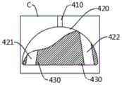
图4为本发明实施例1中提供的切线器的切线件的结构示意图;4 is a schematic structural diagram of the thread cutting member of the thread cutter provided in Embodiment 1 of the present invention;
图5为本发明实施例2中提供的切线器的切线件的结构示意图。FIG. 5 is a schematic structural diagram of a thread cutting member of the thread cutter provided in Embodiment 2 of the present invention.
图标:100-缝合针;110-手持段;120-回弯段;130-针尖;140-穿线孔;150-第一手柄;200-引导筒;210-通缝;220-第二手柄;300-打结器;310-第一主杆;320-打结件;321-第一绕线孔;322-第二绕线孔;330-第三手柄;400-切线器;410-第二主杆;420-切线件;421-第一切线孔;422-第二切线孔;430-切割部;440-第四手柄。Icon: 100-suture needle; 110-hand-held segment; 120-returned segment; 130-needle tip; 140-thread hole; 150-first handle; 200-guide cylinder; 210-through seam; 220-second handle; 300 - knotter; 310-first main rod; 320-knotting piece; 321-first winding hole; 322-second winding hole; 330-third handle; 400-thread cutter; 410-second main Rod; 420 - tangent; 421 - first tangent hole; 422 - second tangent hole; 430 - cutting part; 440 - fourth handle.
具体实施方式Detailed ways
为使本发明实施例的目的、技术方案和优点更加清楚,下面将结合本发明实施例中的附图,对本发明实施例中的技术方案进行清楚、完整地描述,显然,所描述的实施例是本发明一部分实施例,而不是全部的实施例。通常在此处附图中描述和示出的本发明实施例的组件可以以各种不同的配置来布置和设计。In order to make the purposes, technical solutions and advantages of the embodiments of the present invention clearer, the technical solutions in the embodiments of the present invention will be clearly and completely described below with reference to the accompanying drawings in the embodiments of the present invention. Obviously, the described embodiments These are some embodiments of the present invention, but not all embodiments. The components of the embodiments of the invention generally described and illustrated in the drawings herein may be arranged and designed in a variety of different configurations.
因此,以下对在附图中提供的本发明的实施例的详细描述并非旨在限制要求保护的本发明的范围,而是仅仅表示本发明的选定实施例。基于本发明中的实施例,本领域普通技术人员在没有做出创造性劳动前提下所获得的所有其他实施例,都属于本发明保护的范围。Thus, the following detailed description of the embodiments of the invention provided in the accompanying drawings is not intended to limit the scope of the invention as claimed, but is merely representative of selected embodiments of the invention. Based on the embodiments of the present invention, all other embodiments obtained by those of ordinary skill in the art without creative efforts shall fall within the protection scope of the present invention.
应注意到:相似的标号和字母在下面的附图中表示类似项,因此,一旦某一项在一个附图中被定义,则在随后的附图中不需要对其进行进一步定义和解释。It should be noted that like numerals and letters refer to like items in the following figures, so once an item is defined in one figure, it does not require further definition and explanation in subsequent figures.
在本发明的描述中,需要说明的是,若出现术语“中心”、“上”、“下”、“左”、“右”、“竖直”、“水平”、“内”、“外”等指示的方位或位置关系为基于附图所示的方位或位置关系,或者是该发明产品使用时惯常摆放的方位或位置关系,仅是为了便于描述本发明和简化描述,而不是指示或暗示所指的装置或元件必须具有特定的方位、以特定的方位构造和操作,因此不能理解为对本发明的限制。此外,本发明的描述中若出现术语“第一”、“第二”等仅用于区分描述,而不能理解为指示或暗示相对重要性。In the description of the present invention, it should be noted that if the terms "center", "upper", "lower", "left", "right", "vertical", "horizontal", "inner", "outer" appear The azimuth or positional relationship indicated by "" etc. is based on the azimuth or positional relationship shown in the attached drawings, or the azimuth or positional relationship that the product of the invention is usually placed in use, and is only for the convenience of describing the present invention and simplifying the description, rather than indicating Or imply that the device or element referred to must have a particular orientation, be constructed and operate in a particular orientation, and therefore should not be construed as limiting the invention. In addition, if the terms "first", "second" and the like appear in the description of the present invention, they are only used to distinguish the description, and should not be construed as indicating or implying relative importance.
此外,本发明的描述中若出现术语“水平”、“竖直”等术语并不表示要求部件绝对水平或悬垂,而是可以稍微倾斜。如“水平”仅仅是指其方向相对“竖直”而言更加水平,并不是表示该结构一定要完全水平,而是可以稍微倾斜。Furthermore, the appearance of the terms "horizontal", "vertical", etc. in the description of the present invention does not mean that the components are required to be absolutely horizontal or overhang, but rather may be slightly inclined. For example, "horizontal" only means that its direction is more horizontal than "vertical", it does not mean that the structure must be completely horizontal, but can be slightly inclined.
在本发明的描述中,还需要说明的是,除非另有明确的规定和限定,若出现术语“设置”、“安装”、“相连”、“连接”应做广义理解,例如,可以是固定连接,也可以是可拆卸连接,或一体地连接;可以是机械连接,也可以是电连接;可以是直接相连,也可以通过中间媒介间接相连,可以是两个元件内部的连通。对于本领域的普通技术人员而言,可以具体情况理解上述术语在本发明中的具体含义。In the description of the present invention, it should also be noted that, unless otherwise expressly specified and limited, the terms "arranged", "installed", "connected" and "connected" should be understood in a broad sense, for example, it may be a fixed The connection can also be a detachable connection, or an integral connection; it can be a mechanical connection or an electrical connection; it can be a direct connection, or an indirect connection through an intermediate medium, and it can be internal communication between two components. For those of ordinary skill in the art, the specific meanings of the above terms in the present invention can be understood in specific situations.
实施例1:Example 1:
本发明实施例提供一种腔镜穿刺道缝合器,用以由内向外缝合腹腔内层的腹膜的切口,请参照附图1,其包括用于进入腹腔进行穿刺缝合的缝合针100和引导筒200,以及用于方便在腹外对内部打结的打结器300和切线器400,打结器300用于打结缝合线,切线器400用于切断缝合线。An embodiment of the present invention provides an endoscopic puncture suture device for suturing the incision of the peritoneum in the inner layer of the abdominal cavity from the inside to the outside. Please refer to FIG. 1 , which includes a
请参照附图1,所述引导筒200的周壁上开设有沿竖向的通缝210,所述引导筒200设有第二手柄220,所述第二手柄220连接所述引导筒200一端周壁。Referring to FIG. 1 , the peripheral wall of the
请参照附图1,所述缝合针100包括手持段110,手持段110的一端设置第一手柄150,手持段110的另一端形成U型回弯的回弯段120,请参照附图2,回弯段120设置有针尖130,针尖130处设置穿线孔140。Please refer to FIG. 1 , the
为了便于手持操作使用,请参照附图1,所述手持段110长度大于所述回弯段120的长度。In order to facilitate hand-held operation and use, please refer to FIG. 1 , the length of the hand-held
所述缝合针100被配置成能够插入所述引导筒200的内部通道,缝合针100能够在所述引导筒200的内部通道内转动,以使缝合针100具有针尖130的回弯段120远离或者靠近引导筒200的通缝210,通过转动能够使缝合针100从通缝210处穿出引导筒200。The
为了进一步方便移动、转动所述缝合针100和所述引导筒200,所述第一手柄150一端与所述手持段110连接、另一端偏离所述手持段110的轴线设置,所述第二手柄220一端与所述引导筒200周壁连接、另一端偏离所述引导筒200的轴线设置。这种手柄偏置的设置能够进一步方便转动、倾斜、移动缝合针100和引导筒200,并且方便二者配合使用,不容易在缝合针100进出引导筒200时造成阻碍,也不容易在操作缝合针100时遮挡视线。In order to further facilitate the movement and rotation of the
请参照附图1,所述打结器300包括第一主杆310,所述第一主杆310一端设置打结件320、另一端连接有第三手柄330。Referring to FIG. 1 , the
请参照附图3,所述打结件320为板状结构,所述打结件320上设有贯穿板面的第一绕线孔321和第二绕线孔322。Referring to FIG. 3 , the
请参照附图3,所述打结件320朝远离所述第三手柄330的方向逐渐增大,所述第一绕线孔321和所述第二绕线孔322设置于所述打结件320的大端。Referring to FIG. 3 , the knotting
请参照附图3,所述的打结件320大致呈远离所述第三手柄330处大、靠近所述第三手柄330处小的三角形,第一绕线孔321和第二绕线孔322分列于靠近三角形底边的大端,能够方便缝合线两端穿过所述第一绕线孔321和所述第二绕线孔322后归拢于所述第一主杆310处。三角形的边角均设置为圆角、两腰设置成平滑的曲线,这种设置能够方便将打结件320从切口部位取出,减少打结件320与内部组织干扰。Please refer to FIG. 3 , the knotting
请参照附图1,所述切线器400包括第二主杆410,所述第二主杆410一端设置切线件420、另一端连接有第四手柄440。Referring to FIG. 1 , the
请参照附图4,所述切线件420上开设有第一切线孔421和第二切线孔422,所述第一切线孔421和所述第二切线孔422的内壁设置有用于切断缝合线的切割部430。该切割部430可以为设置在切线孔内壁的刃口。Referring to FIG. 4 , the
请参照附图1,为了便于切线件420进入切口,所述的切线件420设置为板状,同时切线件420远离所述第四手柄440处大、靠近所述第四手柄440处小,其侧边为平滑曲线。Please refer to FIG. 1 , in order to facilitate the entry of the
为了尽量避免对腹腔内部组织造成损伤,切割部430隐藏于切线件420内,请参照附图4,所述第一切线孔421和所述第二切线孔422设置于所述切线件420中部,所述第一切线孔421和所述第二切线孔422分别倾斜设置,所述切割部430为切线孔的内壁与切线件420底部形成的锐角,所述锐角处设置刃口。该刃口可以为设置在锐角处的金属薄片,或者可以对锐角边缘加工处理使其具有能够切割的刃口。In order to avoid damage to the internal tissue of the abdominal cavity as much as possible, the cutting
本发明不对缝合针100、引导筒200、打结器300和切线器400的具体尺寸做进一步限制,本实施例中,其具体的尺寸如下:The present invention does not further limit the specific dimensions of the
缝合针100:手持段110为长200mm、直径2mm的光圆直杆,回弯段120与手持段110一体成型,其长度为50mm,回弯段120末端2mm处设置针尖130和穿线孔140,手持段110与回弯段120的净间距为6mm。The suture needle 100: the hand-held
引导筒200:引导筒200恰好能够容许缝合针100穿行其间,引导筒200直径11mm,通缝210恰好容许缝合针100顺利穿过,通缝210宽度为2.5mm。Guide tube 200: the
打结器300:第一主杆310为直径3mm的光圆直杆,打结件320的最宽处为10mm,第一绕线孔321和第二绕线孔322的直径均为2mm。The knotter 300: the first
切线器400:第二主杆410为直径3mm的光圆直杆,切线件420的最宽处为8mm,第一切线孔421和第二切线孔422的直径为2mm,请参照附图4,切线孔上端向第二主杆410靠拢,切线孔的下端与切线件420的底角的距离为1mm。Thread cutter 400: the second
进一步地,所述的缝合针100、引导筒200、打结器300和切线器400的表面均设置为光滑的表面,且除缝合针100的针尖130外,任一边角均设置为圆角。Further, the surfaces of the
本发明实施例提供的腔镜穿刺道缝合器的使用原理如下。The use principle of the endoscopic puncture channel stapler provided by the embodiment of the present invention is as follows.
缝合操作:Stitching operation:
S11:腔镜手术结束后,先保留腔镜镜头在腹腔内做操作引导,接着用引导筒200置换出腔镜操作通道;S11: after the laparoscopic operation is completed, first retain the laparoscopic lens for operation guidance in the abdominal cavity, and then replace the laparoscopic operation channel with the
S12:将全长的缝合线穿过缝合针100的穿线孔140,具有针尖130的回弯段120经引导筒200插入腹腔,注意插入时回弯段120远离通缝210,插入深度以具有穿线孔140的针尖130刚好进入腹腔为宜;S12: Pass the full-length suture thread through the
S13:退出引导筒200,退出时使缝合针100由通缝210穿过,这样可以使引导筒200退出的同时,使缝合针100的回弯段120能够保留在腹腔及穿刺道内;S13: Exit the
S14:将回弯段120的针尖130沿距离破口1.0cm处刺入腹壁,右手执缝合针100的第一手柄150将回弯段120回拉,同时左手将位于回弯段120一侧的皮肤切口拉向远离回弯段120的一侧,然后引导回弯段120的针尖130经腔镜隧道内穿出。此时,用止血钳伸入隧道内夹住缝合线的一端,拉出并暂时固定。需注意的是,拉出长度应适宜,以免缝合线的另一端从穿线孔140脱出。S14: Insert the
S15:缓慢将回弯段120退回腹腔内,注意不要使缝合线从穿线孔140脱落。将缝合针100旋转180°,使回弯段120的针尖130从腹膜破口的另一侧,距离破口1.0cm处刺入腹壁,接着同S14操作使针尖130从隧道内穿出。S15: Slowly retract the
此时将止血钳伸入隧道内夹住缝合线,轻轻拉动,辨别出缝合线游离端后,将游离端缝合线从穿线孔140退出。将缝合线的两端用止血钳夹紧固定,备用。At this time, the hemostatic forceps are inserted into the tunnel to clamp the suture, and the suture is pulled gently. After identifying the free end of the suture, the free end of the suture is withdrawn from the
再缓慢将回弯段120退回腹腔内,使回弯段120针尖130恰好进入腹腔为宜,并对缝合针100稍施拉力,使针尖130固定在腹壁又不至于刺入腹壁,以达到避免针尖130损伤腹腔内容物(如肠管、肝脏等)的目的。此时缝合线应在回弯段120与手持段110形成的“U”型开口之外,即回弯段120与手持段110位于缝合线的同侧,为便于描述,以下将此时缝合针100所在一侧命名为缝合针100侧。Then slowly return the
S16:将引导筒200沿缝合针100再次进入隧道内,注意,操控第二手柄220将引导筒200引导至此时,缝合针100需经通缝210进入引导筒200内。S16: The
S17:双手配合执第一手柄150、第二手柄220,分别操作缝合针100和引导筒200,使回弯段120进入引导筒200内,并转动缝合针100使回弯段120远离通缝210,再同时退出缝合针100与引导筒200,缝合操作结束。S17: Hold the
打结操作:Knotting operation:
S21:缝合完成,退出缝合针100与引导筒200后,先打第一结,打结后将缝合线两端分别穿入第一绕线孔321和第二绕线孔322,左手捏紧缝合线两端,右手沿着缝合线将打结件320推入腔镜隧道内,边推边用力,直到线结收紧。然后缓缓退出打结件320。注意此时缝合线的线结有可能松动,属于正常现象,继续进行下一步。S21: After the suture is completed, after exiting the
S22:将缝合线从第一绕线孔321和第二绕线孔322退出,用同样方法打第二结。第二结应为滑结,将缝合线两端穿入第一绕线孔321和第二绕线孔322,采用与S21中的同样方法,利用打结件320收紧线结。此时虽为滑结,线结不会松动。S22: withdraw the suture from the first winding
注意:滑结是在常规操作下不应出现的打结方法,其所打线结不牢固,施加稍大拉力使容易滑动,但此处通过打滑结,可暂时起到压线作用,使线结不能松动,方便进行下一步操作。Note: The slip knot is a knotting method that should not occur under normal operation. The knot of the thread is not firm, and a slightly larger pulling force is applied to make it easy to slide. The knot cannot be loosened, which is convenient for the next operation.
S23:退出打结件320,打第三结,注意此时打结方向与第二结方向相反,线结收紧后可与第二结形成标准方结,至此打结完成。退出打结件320。S23: Exit the
S24:将缝合线两端分别穿入第一切线孔421和第二切线孔422,左手捏紧缝合线两端,将切线器400沿着缝合线缓慢推入隧道内。遇到阻力时,将缝合线与切线器400的第二主杆410捏紧固定,然后轻轻左右摆动切线器400,此时在第一切线孔421和第二切线孔422内缘锐利刃口的作用下,缝合线的一端将在距离线结0.1cm处先被切断,缝合线的另一端在距离线结0.1cm处受刃口作用亦形成部分离断,继续左右摆动切线件420,缝合线的另一端将继之被切断,最后退出切线器400,至此打结操作结束。S24: Insert the two ends of the suture into the first
如腹膜破口较长需缝合两针以上,可重复上述操作。皮肤缝合不再赘述。If the peritoneal incision is long and requires more than two sutures, the above operation can be repeated. Skin sutures are not repeated here.
实施例2:Example 2:
在实施例1的基础上,为了进一步方便快速切断缝合线,请参照附图5所示,所述切线件420底部设置为内凹的弧形,所述第一切线孔421和所述第二切线孔422靠近所述第四手柄440的一端朝所述第二主杆410倾斜。On the basis of Example 1, in order to further facilitate the quick cutting of the suture, please refer to FIG. 5 , the bottom of the
通过将切线件420底部设置为内凹的弧形结构,请结合附图4和附图5所示,切线孔内壁与切线件420底部形成的锐角的角度更小,从而使刃口更为锐利,更容易切断缝合线。同时内凹的构造,使得刃口位于切线件420的中部,不容易接触、损伤腹腔内部组织。By setting the bottom of the
需要说明的是,本发明提供的缝合器组件及其操作方法,还可以用于缝合其他物品的切口,例如:皮具制品的缝合,从皮具制品的外部,对切口的内部进行缝合。采用该缝合方法可以将不便于翻转皮面的皮具缝合,缝合部位位于皮具内层,外部大方美观。缝合完成后,还可在皮具外部采用粘合剂进行粘合,使切口进一步拉结。It should be noted that the suture assembly and its operation method provided by the present invention can also be used to suture the incision of other articles, for example, the suture of leather goods, from the outside of the leather goods to the inside of the incision. The suture method can be used to suture the leather goods which are inconvenient to turn the leather surface. After the stitching is complete, adhesives can also be used on the outside of the leather goods to further tie the incision.
以上所述仅为本发明的优选实施例而已,并不用于限制本发明,对于本领域的技术人员来说,本发明可以有各种更改和变化。凡在本发明的精神和原则之内,所作的任何修改、等同替换、改进等,均应包含在本发明的保护范围之内。The above descriptions are only preferred embodiments of the present invention, and are not intended to limit the present invention. For those skilled in the art, the present invention may have various modifications and changes. Any modification, equivalent replacement, improvement, etc. made within the spirit and principle of the present invention shall be included within the protection scope of the present invention.
Claims (7)
Priority Applications (1)
| Application Number | Priority Date | Filing Date | Title |
|---|---|---|---|
| CN201810812970.XACN109157250B (en) | 2018-07-23 | 2018-07-23 | Endoscope puncture channel stitching instrument |
Applications Claiming Priority (1)
| Application Number | Priority Date | Filing Date | Title |
|---|---|---|---|
| CN201810812970.XACN109157250B (en) | 2018-07-23 | 2018-07-23 | Endoscope puncture channel stitching instrument |
Publications (2)
| Publication Number | Publication Date |
|---|---|
| CN109157250A CN109157250A (en) | 2019-01-08 |
| CN109157250Btrue CN109157250B (en) | 2020-08-11 |
Family
ID=64898120
Family Applications (1)
| Application Number | Title | Priority Date | Filing Date |
|---|---|---|---|
| CN201810812970.XAExpired - Fee RelatedCN109157250B (en) | 2018-07-23 | 2018-07-23 | Endoscope puncture channel stitching instrument |
Country Status (1)
| Country | Link |
|---|---|
| CN (1) | CN109157250B (en) |
Families Citing this family (2)
| Publication number | Priority date | Publication date | Assignee | Title |
|---|---|---|---|---|
| CN111544067A (en)* | 2019-02-12 | 2020-08-18 | 苗瑞超 | Reverse laparoscope incision stitching instrument |
| CN114081555B (en)* | 2021-07-27 | 2025-02-11 | 中国人民解放军总医院第四医学中心 | A deep tissue suturing device |
Family Cites Families (14)
| Publication number | Priority date | Publication date | Assignee | Title |
|---|---|---|---|---|
| US5176691A (en)* | 1990-09-11 | 1993-01-05 | Pierce Instruments, Inc. | Knot pusher |
| US5439469A (en)* | 1993-11-05 | 1995-08-08 | Advanced Surgical, Inc. | Wound closure device |
| US7488327B2 (en)* | 2004-04-12 | 2009-02-10 | Synthes (U.S.A.) | Free hand drill guide |
| US9072476B2 (en)* | 2005-09-23 | 2015-07-07 | Medtronic Minimed, Inc. | Flexible sensor apparatus |
| CN201185959Y (en)* | 2008-04-13 | 2009-01-28 | 孙友良 | Malleolus medialis puncture needle locating guider |
| CN101810506A (en)* | 2010-01-29 | 2010-08-25 | 李冀 | Percutaneous bone grafting apparatus |
| CN203841745U (en)* | 2014-04-02 | 2014-09-24 | 中山大学附属第三医院 | Endoscopic two-way knot pusher |
| CN103961146B (en)* | 2014-05-06 | 2016-08-24 | 李达周 | Scope suture cutter |
| CN105832414B (en)* | 2015-03-02 | 2018-07-13 | 苏州市立普医疗科技有限公司 | Body puncture frame needle tray guider |
| CN204890094U (en)* | 2015-08-13 | 2015-12-23 | 宋留红 | Boring sleeve of thighbone |
| CN205814284U (en)* | 2016-06-23 | 2016-12-21 | 湖州市妇幼保健院 | Branchofiberoscope guide |
| CN106308894A (en)* | 2016-09-07 | 2017-01-11 | 重庆科杰医疗设备有限公司 | Independent type puncture needle protection device |
| CN106264635A (en)* | 2016-09-29 | 2017-01-04 | 江苏省人民医院 | A kind of fibrous ring stitching devices being easy to separate suture |
| CN206979517U (en)* | 2017-01-17 | 2018-02-09 | 陈晓东 | Fibrous ring stitching unstrument under a kind of scope |
- 2018
- 2018-07-23CNCN201810812970.XApatent/CN109157250B/ennot_activeExpired - Fee Related
Also Published As
| Publication number | Publication date |
|---|---|
| CN109157250A (en) | 2019-01-08 |
Similar Documents
| Publication | Publication Date | Title |
|---|---|---|
| US8876701B2 (en) | Medical systems, devices and methods for endoscopically suturing perforations | |
| US5449367A (en) | Pre-tied knot for surgical use and method of using same | |
| US9155534B2 (en) | Side-loaded medical implement particularly useful in arthroscopic surgery | |
| CN110545736B (en) | Endovascular surgery system | |
| US20040087978A1 (en) | Surgical fascia closure instrument, guide and method | |
| US20050090841A1 (en) | Suturing instrument with needle dock | |
| JP6302842B2 (en) | Insertion device and insertion system for laparoscopic instruments | |
| US20070185503A1 (en) | Suture instrument | |
| US20150257751A1 (en) | Suturing device | |
| US9301748B2 (en) | Suture apparatus, system and method | |
| JP2007090062A (en) | Suture tool | |
| JP5462301B2 (en) | Needle unit | |
| US11696780B2 (en) | Papillotome for percutaneous endoscopic gastrostomy | |
| US10660636B2 (en) | Suture apparatus, system and method | |
| JP2011072790A (en) | Wound closure device including direct-driven needle | |
| US10973510B2 (en) | Needle loading unit for surgical suturing apparatus | |
| CN109157250B (en) | Endoscope puncture channel stitching instrument | |
| EP2779912B1 (en) | A surgical device | |
| US10743862B1 (en) | Laparoscopic suturing device and methods of use | |
| JP2011098160A (en) | Surgery needle holder | |
| US9566059B2 (en) | Laparoscopic device for anchoring an organ to thoracic diaphragm | |
| CN102824201A (en) | Circular purse-string forceps capable of automatically sewing in purse way | |
| CN221431160U (en) | Puncture crochet needle capable of simplifying operation | |
| US20190239870A1 (en) | Laproscopic knot applicator | |
| CN103405252A (en) | Surgical suture needle for laparoscopic partial nephrectomy |
Legal Events
| Date | Code | Title | Description |
|---|---|---|---|
| PB01 | Publication | ||
| PB01 | Publication | ||
| SE01 | Entry into force of request for substantive examination | ||
| SE01 | Entry into force of request for substantive examination | ||
| GR01 | Patent grant | ||
| GR01 | Patent grant | ||
| CF01 | Termination of patent right due to non-payment of annual fee | ||
| CF01 | Termination of patent right due to non-payment of annual fee | Granted publication date:20200811 |