CN109152900B - suction equipment - Google Patents
suction equipmentDownload PDFInfo
- Publication number
- CN109152900B CN109152900BCN201780028193.3ACN201780028193ACN109152900BCN 109152900 BCN109152900 BCN 109152900BCN 201780028193 ACN201780028193 ACN 201780028193ACN 109152900 BCN109152900 BCN 109152900B
- Authority
- CN
- China
- Prior art keywords
- exhalation
- interior
- exhaust gas
- inspiratory
- gas
- Prior art date
- Legal status (The legal status is an assumption and is not a legal conclusion. Google has not performed a legal analysis and makes no representation as to the accuracy of the status listed.)
- Active
Links
Images


Classifications
- A—HUMAN NECESSITIES
- A61—MEDICAL OR VETERINARY SCIENCE; HYGIENE
- A61M—DEVICES FOR INTRODUCING MEDIA INTO, OR ONTO, THE BODY; DEVICES FOR TRANSDUCING BODY MEDIA OR FOR TAKING MEDIA FROM THE BODY; DEVICES FOR PRODUCING OR ENDING SLEEP OR STUPOR
- A61M16/00—Devices for influencing the respiratory system of patients by gas treatment, e.g. ventilators; Tracheal tubes
- A61M16/0087—Environmental safety or protection means, e.g. preventing explosion
- A61M16/009—Removing used or expired gases or anaesthetic vapours
- A—HUMAN NECESSITIES
- A61—MEDICAL OR VETERINARY SCIENCE; HYGIENE
- A61M—DEVICES FOR INTRODUCING MEDIA INTO, OR ONTO, THE BODY; DEVICES FOR TRANSDUCING BODY MEDIA OR FOR TAKING MEDIA FROM THE BODY; DEVICES FOR PRODUCING OR ENDING SLEEP OR STUPOR
- A61M16/00—Devices for influencing the respiratory system of patients by gas treatment, e.g. ventilators; Tracheal tubes
- A61M16/06—Respiratory or anaesthetic masks
- A61M16/0605—Means for improving the adaptation of the mask to the patient
- A61M16/0611—Means for improving the adaptation of the mask to the patient with a gusset portion
- A—HUMAN NECESSITIES
- A61—MEDICAL OR VETERINARY SCIENCE; HYGIENE
- A61M—DEVICES FOR INTRODUCING MEDIA INTO, OR ONTO, THE BODY; DEVICES FOR TRANSDUCING BODY MEDIA OR FOR TAKING MEDIA FROM THE BODY; DEVICES FOR PRODUCING OR ENDING SLEEP OR STUPOR
- A61M16/00—Devices for influencing the respiratory system of patients by gas treatment, e.g. ventilators; Tracheal tubes
- A61M16/08—Bellows; Connecting tubes ; Water traps; Patient circuits
- A61M16/0816—Joints or connectors
- A—HUMAN NECESSITIES
- A61—MEDICAL OR VETERINARY SCIENCE; HYGIENE
- A61M—DEVICES FOR INTRODUCING MEDIA INTO, OR ONTO, THE BODY; DEVICES FOR TRANSDUCING BODY MEDIA OR FOR TAKING MEDIA FROM THE BODY; DEVICES FOR PRODUCING OR ENDING SLEEP OR STUPOR
- A61M16/00—Devices for influencing the respiratory system of patients by gas treatment, e.g. ventilators; Tracheal tubes
- A61M16/10—Preparation of respiratory gases or vapours
- A—HUMAN NECESSITIES
- A61—MEDICAL OR VETERINARY SCIENCE; HYGIENE
- A61M—DEVICES FOR INTRODUCING MEDIA INTO, OR ONTO, THE BODY; DEVICES FOR TRANSDUCING BODY MEDIA OR FOR TAKING MEDIA FROM THE BODY; DEVICES FOR PRODUCING OR ENDING SLEEP OR STUPOR
- A61M2202/00—Special media to be introduced, removed or treated
- A61M2202/02—Gases
- A61M2202/0208—Oxygen
- A—HUMAN NECESSITIES
- A61—MEDICAL OR VETERINARY SCIENCE; HYGIENE
- A61M—DEVICES FOR INTRODUCING MEDIA INTO, OR ONTO, THE BODY; DEVICES FOR TRANSDUCING BODY MEDIA OR FOR TAKING MEDIA FROM THE BODY; DEVICES FOR PRODUCING OR ENDING SLEEP OR STUPOR
- A61M2202/00—Special media to be introduced, removed or treated
- A61M2202/02—Gases
- A61M2202/0266—Nitrogen (N)
- A61M2202/0283—Nitrous oxide (N2O)
- A—HUMAN NECESSITIES
- A61—MEDICAL OR VETERINARY SCIENCE; HYGIENE
- A61M—DEVICES FOR INTRODUCING MEDIA INTO, OR ONTO, THE BODY; DEVICES FOR TRANSDUCING BODY MEDIA OR FOR TAKING MEDIA FROM THE BODY; DEVICES FOR PRODUCING OR ENDING SLEEP OR STUPOR
- A61M2206/00—Characteristics of a physical parameter; associated device therefor
- A61M2206/10—Flow characteristics
- A61M2206/11—Laminar flow
- A—HUMAN NECESSITIES
- A61—MEDICAL OR VETERINARY SCIENCE; HYGIENE
- A61M—DEVICES FOR INTRODUCING MEDIA INTO, OR ONTO, THE BODY; DEVICES FOR TRANSDUCING BODY MEDIA OR FOR TAKING MEDIA FROM THE BODY; DEVICES FOR PRODUCING OR ENDING SLEEP OR STUPOR
- A61M2210/00—Anatomical parts of the body
- A61M2210/06—Head
- A61M2210/0618—Nose
Landscapes
- Health & Medical Sciences (AREA)
- Life Sciences & Earth Sciences (AREA)
- Engineering & Computer Science (AREA)
- Anesthesiology (AREA)
- Pulmonology (AREA)
- General Health & Medical Sciences (AREA)
- Heart & Thoracic Surgery (AREA)
- Hematology (AREA)
- Emergency Medicine (AREA)
- Biomedical Technology (AREA)
- Public Health (AREA)
- Animal Behavior & Ethology (AREA)
- Veterinary Medicine (AREA)
- Biodiversity & Conservation Biology (AREA)
- Ecology (AREA)
- Environmental & Geological Engineering (AREA)
- Environmental Sciences (AREA)
- Respiratory Apparatuses And Protective Means (AREA)
Abstract
Translated fromChinese
Description
Translated fromChinese技术领域technical field
本发明涉及呼吸或吸气系统,并且更具体地,涉及用于在医疗和牙科气体的施用时使用的设备。The present invention relates to breathing or inspiratory systems and, more particularly, to devices for use in the administration of medical and dental gases.
背景技术Background technique
用于对个体施用可呼吸气体的吸气或呼吸系统是众所周知的。特别重要的是在医疗和牙科领域中用于对患者分配医疗和牙科气体(诸如麻醉和镇痛气体以及氧气和氧化亚氮)时采用的设备。Inspiratory or respiratory systems for administering breathable gases to individuals are well known. Of particular importance are devices employed in the medical and dental fields for dispensing medical and dental gases, such as anesthetic and analgesic gases as well as oxygen and nitrous oxide, to patients.
通常,吸气系统包括选定的加压气体源以及用于将气体递送到患者的外部呼吸器官的装置。诸如面罩等呼吸装置配合到患者的面部以包围鼻部和/或口部。所述源可能是便携式或固定的,通常包括流量调节器。通常呈柔性软管的形式的递送导管在所述源与呼吸装置之间连通。可选地,系统可以包括扫气设备,所述扫气设备包括从呼吸装置延伸到真空源的返回导管。Typically, an inspiratory system includes a selected source of pressurized gas and means for delivering the gas to the patient's external respiratory organs. A breathing apparatus, such as a mask, fits over a patient's face to enclose the nose and/or mouth. The source may be portable or stationary and typically includes a flow regulator. A delivery catheter, usually in the form of a flexible hose, communicates between the source and the breathing apparatus. Optionally, the system may include a scavenging device including a return conduit extending from the breathing apparatus to the vacuum source.
现有技术已经设计呈许多结构配置的大量个人呼吸装置。这些个人呼吸装置通常称为吸气面罩或面具,用于多种功能。举例来说,已知在患者的口部和鼻部上方延伸的面罩,而其他一些面罩仅接收鼻部。通常,面罩包括用于附接气体递送导管的配件。在一些例子中,在面罩中并入有呼气阀,以防止周围空气的进入。The prior art has designed a large number of personal respiratory devices in many structural configurations. Often referred to as inhalation masks or masks, these personal breathing devices are used for a variety of functions. For example, masks are known that extend over a patient's mouth and nose, while some other masks only receive the nose. Typically, masks include fittings for attaching gas delivery conduits. In some examples, an exhalation valve is incorporated into the mask to prevent the ingress of ambient air.
认识到关于呼出气体的收集和弃置的问题,本领域的技术人员已经开发了对于吸气面罩有用的多种解决方案,诸如扫气阀附件、对于吸气面罩有用的扫气罩以及扫气回路。虽然这些现有技术实例起初似乎是足够的,但在现有技术扫气解决方案中固有的结构复杂性已经证明是不令人满意的,因而现有技术中必须有继续的改进。Recognizing the problems with the collection and disposal of exhaled gas, those skilled in the art have developed various solutions useful for inspiratory masks, such as scavenging valve accessories, scavenging masks useful for inspiratory masks, and scavenging circuits . While these prior art examples initially appeared to be adequate, the structural complexity inherent in prior art scavenging solutions has proven unsatisfactory, and there must be continued improvements in the prior art.
发明内容SUMMARY OF THE INVENTION
根据本发明的原理,一种用于对个体施用可呼吸气体以及用于从所述个体扫除废气的设备,所述个体包括含有用于接收可呼吸气体并且用于排出废气的呼吸器官的面部区域,所述设备包括主体、真空软管和扫气阀。所述主体是杯形的,包括第一侧面和第二侧面,并且可抵靠所述面部区域接收以用于封围所述呼吸器官。吸气构件从所述主体的所述第一侧面延伸。呼气构件从所述主体的所述第二侧面延伸。所述真空软管用于将真空源联接到所述呼气构件。所述扫气阀联接到所述真空软管。所述吸气构件用于将可呼吸气体施用到所述主体中,所述呼气构件用于将废气从所述主体排出到所述真空软管中,并且所述扫气阀用于穿过其将废气从所述真空软管排出到大气。所述主体包括限定主体内部的内表面,所述吸气构件进一步用于将可呼吸气体从所述吸气构件的入口施用到所述内部中,并且所述呼气构件进一步用于将废气通过所述呼气构件的入口从所述内部排出到所述真空软管。所述主体的所述内表面中的凹入表面轮廓从所述吸气构件的所述出口延伸到所述呼气构件的所述入口。当可呼吸气体从所述吸气构件的所述出口施加到所述内部时,所述凹入表面轮廓与所述吸气构件的所述出口协作以形成从所述吸气构件的所述出口到所述内部的可呼吸气体的层流。当废气被呼出到所述内部中时,所述凹入表面轮廓与所述呼气构件的所述入口协作以形成从所述内部到所述呼气构件的所述入口的废气的层流。所述扫气阀进一步用于禁止气体穿过其从所述大气流入所述真空软管中。In accordance with the principles of the present invention, an apparatus for administering breathable gas to an individual and for scavenging exhaust gas from the individual, the individual comprising a facial region containing a respiratory organ for receiving breathable gas and for expelling exhaust gas , the device includes a main body, a vacuum hose and a scavenging valve. The body is cup-shaped, includes a first side and a second side, and is receivable against the face region for enclosing the respiratory organ. A getter member extends from the first side of the body. An exhalation member extends from the second side of the body. The vacuum hose is used to couple a vacuum source to the expiratory member. The purge valve is coupled to the vacuum hose. The inhalation member is for administering breathable gas into the body, the exhalation member is for expelling exhaust gas from the main body into the vacuum hose, and the scavenging valve is for passing through It exhausts the exhaust gas from the vacuum hose to the atmosphere. The body includes an inner surface defining an interior of the body, the inspiratory member is further for administering breathable gas into the interior from an inlet of the inspiratory member, and the expiratory member is further for passing exhaust gas through The inlet of the exhalation member discharges from the interior to the vacuum hose. A concave surface profile in the inner surface of the body extends from the outlet of the inspiratory member to the inlet of the expiratory member. The concave surface profile cooperates with the outlet of the inspiratory member to form the outlet from the inspiratory member when breathable gas is applied to the interior from the outlet of the inspiratory member Laminar flow of breathable gas to the interior. The concave surface profile cooperates with the inlet of the exhalation member to form a laminar flow of exhaust gas from the interior to the inlet of the exhalation member when the exhaust gas is exhaled into the interior. The scavenging valve is further configured to inhibit the flow of gas from the atmosphere therethrough into the vacuum hose.
根据本发明的原理,一种用于对个体施用可呼吸气体以及用于从所述个体扫除废气的设备,所述个体包括含有用于接收可呼吸气体并且用于排出废气的呼吸器官的面部区域,所述设备包括主体、真空软管和扫气阀。所述主体是杯形的,包括第一侧面和第二侧面,并且可抵靠所述面部区域接收以用于封围所述呼吸器官。吸气构件从所述主体的所述第一侧面延伸。呼气构件从所述主体的所述第二侧面延伸。真空软管将真空源联接到所述呼气构件。扫气阀在所述呼气构件与所述真空源之间联接到所述真空软管。所述吸气构件用于将可呼吸气体施用到所述主体中,所述呼气构件用于将废气从所述主体排出到所述真空软管中,并且所述扫气阀用于穿过其将废气从所述真空软管排出到所述呼气构件与所述真空源之间的大气。所述主体包括限定主体内部的内表面,所述吸气构件进一步用于将可呼吸气体从所述吸气构件的入口施用到所述内部中,并且所述呼气构件进一步用于将废气通过所述呼气构件的入口从所述内部排出到所述真空软管。所述主体的所述内表面中的凹入表面轮廓从所述吸气构件的所述出口延伸到所述呼气构件的所述入口。当可呼吸气体从所述吸气构件的所述出口施加到所述内部时,所述凹入表面轮廓与所述吸气构件的所述出口协作以形成从所述吸气构件的所述出口到所述内部的可呼吸气体的层流。当废气被呼出到所述内部中时,所述凹入表面轮廓与所述呼气构件的所述入口协作以形成从所述内部到所述呼气构件的所述入口的废气的层流。所述扫气阀进一步用于禁止气体穿过其从所述大气流入所述真空软管中。In accordance with the principles of the present invention, an apparatus for administering breathable gas to an individual and for scavenging exhaust gas from the individual, the individual comprising a facial region containing a respiratory organ for receiving breathable gas and for expelling exhaust gas , the device includes a main body, a vacuum hose and a scavenging valve. The body is cup-shaped, includes a first side and a second side, and is receivable against the face region for enclosing the respiratory organ. A getter member extends from the first side of the body. An exhalation member extends from the second side of the body. A vacuum hose couples a vacuum source to the exhalation member. A purge valve is coupled to the vacuum hose between the exhalation member and the vacuum source. The inhalation member is for administering breathable gas into the body, the exhalation member is for expelling exhaust gas from the main body into the vacuum hose, and the scavenging valve is for passing through It exhausts exhaust gas from the vacuum hose to the atmosphere between the exhalation member and the vacuum source. The body includes an inner surface defining an interior of the body, the inspiratory member is further for administering breathable gas into the interior from an inlet of the inspiratory member, and the expiratory member is further for passing exhaust gas through The inlet of the exhalation member discharges from the interior to the vacuum hose. A concave surface profile in the inner surface of the body extends from the outlet of the inspiratory member to the inlet of the expiratory member. The concave surface profile cooperates with the outlet of the inspiratory member to form the outlet from the inspiratory member when breathable gas is applied to the interior from the outlet of the inspiratory member Laminar flow of breathable gas to the interior. The concave surface profile cooperates with the inlet of the exhalation member to form a laminar flow of exhaust gas from the interior to the inlet of the exhalation member when the exhaust gas is exhaled into the interior. The scavenging valve is further configured to inhibit the flow of gas from the atmosphere therethrough into the vacuum hose.
根据本发明的原理,一种用于对个体施用可呼吸气体以及用于从所述个体扫除废气的设备,所述个体包括含有用于接收可呼吸气体并且用于排出废气的呼吸器官的面部区域,所述设备包括主体和呼吸器回路。所述主体是杯形的,包括第一侧面和第二侧面,并且可抵靠所述面部区域接收以用于封围所述呼吸器官。吸气构件从所述主体的所述第一侧面延伸。呼气构件从所述主体的所述第二侧面延伸。呼吸器回路包括将气体源联接到所述吸气构件的递送软管、将真空源联接到所述呼气构件的真空软管、以及在所述呼气构件与所述真空源之间联接到所述真空软管的扫气阀。所述递送软管用于将可呼吸气体从所述气体源递送到所述吸气构件,所述吸气构件用于将可呼吸气体施用到所述主体中,所述呼气构件用于将废气从所述主体排出到所述真空软管中,并且所述扫气阀用于穿过其将废气从所述真空软管排出到所述呼气构件与所述真空源之间的大气。所述主体包括限定主体内部的内表面,所述吸气构件进一步用于将可呼吸气体从所述吸气构件的入口施用到所述内部中,并且所述呼气构件进一步用于将废气通过所述呼气构件的入口从所述内部排出到所述真空软管。所述主体的所述内表面中的凹入表面轮廓从所述吸气构件的所述出口延伸到所述呼气构件的所述入口。当可呼吸气体从所述吸气构件的所述出口施加到所述内部时,所述凹入表面轮廓与所述吸气构件的所述出口协作以形成从所述吸气构件的所述出口到所述内部的可呼吸气体的层流。当废气被呼出到所述内部中时,所述凹入表面轮廓与所述呼气构件的所述入口协作以形成从所述内部到所述呼气构件的所述入口的废气的层流。所述扫气阀进一步用于禁止气体穿过其从所述大气流入所述真空软管中。In accordance with the principles of the present invention, an apparatus for administering breathable gas to an individual and for scavenging exhaust gas from the individual, the individual comprising a facial region containing a respiratory organ for receiving breathable gas and for expelling exhaust gas , the device includes a main body and a ventilator circuit. The body is cup-shaped, includes a first side and a second side, and is receivable against the face region for enclosing the respiratory organ. A getter member extends from the first side of the body. An exhalation member extends from the second side of the body. A respirator circuit includes a delivery hose coupling a gas source to the inspiratory member, a vacuum hose coupling a vacuum source to the expiratory member, and a vacuum hose coupled between the expiratory member and the vacuum source The scavenging valve of the vacuum hose. The delivery hose is for delivering breathable gas from the gas source to the inspiratory member for administering breathable gas into the body, the expiratory member for delivering breathable gas to the body. Exhaust gas is exhausted from the body into the vacuum hose, and the purge valve is used to exhaust exhaust gas therethrough from the vacuum hose to the atmosphere between the exhalation member and the vacuum source. The body includes an inner surface defining an interior of the body, the inspiratory member is further for administering breathable gas into the interior from an inlet of the inspiratory member, and the expiratory member is further for passing exhaust gas through The inlet of the exhalation member discharges from the interior to the vacuum hose. A concave surface profile in the inner surface of the body extends from the outlet of the inspiratory member to the inlet of the expiratory member. The concave surface profile cooperates with the outlet of the inspiratory member to form the outlet from the inspiratory member when breathable gas is applied to the interior from the outlet of the inspiratory member Laminar flow of breathable gas to the interior. The concave surface profile cooperates with the inlet of the exhalation member to form a laminar flow of exhaust gas from the interior to the inlet of the exhalation member when the exhaust gas is exhaled into the interior. The scavenging valve is further configured to inhibit the flow of gas from the atmosphere therethrough into the vacuum hose.
附图说明Description of drawings
参见附图:See attached image:
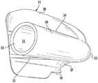
图1是用于对个体施用可呼吸气体以及用于从所述个体扫除废气的吸气设备的透视图,所述个体包括含有用于接收可呼吸气体且用于排出废气的呼吸器官的面部区域,所述吸气设备包括面罩,以及用于将可呼吸气体递送到面罩且用于从面罩排出废气的呼吸器回路,所述呼吸器回路包括用于将气体源联接到面罩的吸气构件的递送软管、用于将真空源联接到面罩的呼气构件的真空软管、以及联接到真空软管以用于将废气从真空软管排出到远离面罩的位置处的大气的扫气阀;1 is a perspective view of an inhalation device for administering breathable gas to an individual including a facial region containing a respiratory organ for receiving breathable gas and for expelling exhaust gas, and for scavenging exhaust gas from the individual , the inspiratory device includes a mask, and a respirator circuit for delivering breathable gas to the mask and for expelling exhaust gas from the mask, the respirator circuit including a gas source for coupling a gas source to an inspiratory member of the mask a delivery hose, a vacuum hose for coupling a vacuum source to an exhalation member of the mask, and a purge valve coupled to the vacuum hose for exhausting exhaust gas from the vacuum hose to atmosphere at a location remote from the mask;
图2和图3是对应于图1的分段透视图,图示了联接到面罩的吸气构件的递送软管,并且图示了联接到面罩的呼气构件的真空软管;2 and 3 are segmented perspective views corresponding to FIG. 1, illustrating a delivery hose coupled to an inspiratory member of a mask, and illustrating a vacuum hose coupled to an expiratory member of the mask;
图4是对应于图1的分段分解视图,示出了用于将递送软管和真空软管分别联接到吸气构件和呼气构件的适配器;Figure 4 is a fragmented exploded view corresponding to Figure 1 showing adapters for coupling the delivery hose and the vacuum hose to the inspiratory and expiratory members, respectively;
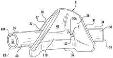
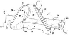
图5至图13是对应于图1的面罩的透视图;5-13 are perspective views corresponding to the mask of FIG. 1;
图14和图15是对应于图1的分段透视图,图示了将递送软管捆扎到扫气阀的联接件;并且Figures 14 and 15 are segmented perspective views corresponding to Figure 1 illustrating the coupling for bundling the delivery hose to the scavenging valve; and
图16是对应于图14和图15的分解视图。FIG. 16 is an exploded view corresponding to FIGS. 14 and 15 .
具体实施方式Detailed ways
本发明尤其提供一种用于对个体施用可呼吸气体以及用于从所述个体扫除废气的新型且改进的吸气设备,所述个体包括含有用于接收可呼吸气体且用于排出废气的呼吸器官的面部区域。The present invention provides, among other things, a new and improved inspiratory device for administering breathable gas to an individual, and for scavenging exhaust gas from said individual, the individual comprising a breath containing breathable gas for receiving breathable gas and for expelling exhaust gas The facial area of the organ.
转到附图,其中相同附图标记在若干视图中指示对应元件,首先关注图1,其中见到用于对个体施用可呼吸气体以及用于从所述个体扫除废气的吸气设备20,所述个体包括含有用于接收可呼吸气体且用于排出废气的呼吸器官的面部区域。吸气设备20包括面罩21和呼吸器回路22,所述呼吸器回路22用于将可呼吸气体递送到面罩21、用于从面罩21扫除废气并且用于将废气排放到相对于面罩21在远处位置的大气。Turning to the drawings, wherein like reference numerals designate corresponding elements throughout the several views, attention is firstly to FIG. 1, in which an
参见图5至图13,在相关部分中,面罩21包括主体30。主体60是杯形的,可抵靠面部区域接收以用于封围呼吸器官,并且是一体形成的。主体30包括相对的侧面31和32、在主体30的前部的前部中点33、吸气构件35以及呼气构件36。吸气构件34从主体30的侧面31延伸,并且呼气构件36从主体30的侧面32延伸。主体30以向后导向的周边边缘46终止。边缘36是在主体30的后部的主体30的终端部分。主体30还包括外表面37和内表面38。内表面38在主体30的后部从边缘40向内朝向主体30的前部延伸,并且界定面罩21的主体30的内部40。主体30的大小被设定成接收个体的外部呼吸器官,具体来说是鼻部。边缘36带有轮廓以抵靠面部区域包围鼻部接收。当边缘36抵靠面部区域包围鼻部接收时,内部40接收个体的鼻部。主体30由柔性弹性材料模制而成,诸如示例性商标
吸气构件34用于将可呼吸气体施用到主体30中,具体来说进入主体30的内部40,并且呼气构件35用于从主体30排出废气,具体来说从主体21的内部40。吸气构件34,即导管,是圆柱形侧壁50,其具有界定孔隙51的圆柱形内表面50A,所述孔隙从入口52延伸到去往内部40的出口53。吸气构件34从主体30的侧面31向后成角度地从出口53与内部40连通地突出到入口52。呼气构件35,即导管,是圆柱形侧壁60,其具有限定孔隙61的圆柱形内表面60A,所述孔隙从出口62延伸到去往内部40的入口63。呼气构件35从主体30的侧面32向后成角度地从入口63与内部40连通地突出到出口62。
参见图1,呼吸器回路22包括:柔性递送软管70,其用于将气体源71联接到面罩21的吸气构件34;柔性真空软管72,其用于将真空源73联接到面罩21的呼气构件35;以及扫气阀75,其远离面罩21联接到真空软管72,用于将废气从真空软管72排出到远离面罩21的大气或另外在远离面罩21的位置的大气。气体源71用于将可呼吸气体递送到递送软管70,递送软管70用于将来自气体源71的可呼吸气体递送到吸气构件34,吸气构件34用于将从递送软管70施加于其的可呼吸气体施用到主体30中,具体来说进入主体30的内部40,呼气构件35用于将废气从主体30、具体来说从主体30的内部40排出到真空软管72中,扫气阀75用于穿过其将废气从真空软管72排出到呼气构件35与真空源73之间的在远离面罩21的位置的大气,并且真空源用于对真空软管72施加真空以用于从主体30吸取废气,具体来说通过呼气构件35从主体30的内部40进入真空软管72。1 , the
在图1、图2和图3中,递送软管70的出口端70A借助一个连接器80A连接到吸气构件34的圆柱形侧壁50的入口52,并且真空软管72的入口端72A借助另一个完全相同的连接器80A连接到呼气构件35的圆柱形侧壁60的出口62。连接器80A用于准许可呼吸气体进入吸气构件34,并且连接器80B用于从呼气构件35传导废气。1, 2 and 3, the
连接器80A和80B是完全相同的。在图4中,连接器80A和80B各自包括具有相对末端82和83的圆柱形主体81以及通过其中从末端82延伸到末端83的孔隙84。连接器80A的末端82可以配合且密封方式接合于吸气构件34的入口52内,并且连接器80A的末端83可以配合且密封方式接合于递送软管70的出口端70A内。连接器80B的末端82可以配合且密封方式接合于呼气构件35的出口62内,并且连接器80B的末端83可以配合且密封方式接合于真空软管72的入口72A内。
在图1、图2和图3中,递送软管70的出口端70A借助连接器80A连接到吸气构件34的圆柱形侧壁50的入口52,并且真空软管72的入口端72A借助连接器80B连接到呼气构件35的圆柱形侧壁60的出口62,连接器80A用于准许可呼吸气体进入吸气构件34,并且连接器80B用于从呼气构件35传导废气。递送软管70从借助连接器80A联接到吸气构件34的入口52的出口端70A延伸到气体源71。真空软管72从借助连接器80B联接到呼气构件35的出口62的入口端72A延伸到真空源73。在图1中,联接到真空软管72的扫气阀75与面罩21间隔开,并且在呼气构件35与真空源73之间的远离面罩21的位置处。In Figures 1, 2 and 3, the
在使用中,气体源71将可呼吸气体施加到递送软管70,所述递送软管70将可呼吸气体传递到吸气构件34。吸气构件34又将来自递送软管70的可呼吸气体传递到主体30,具体来说传递到主体30的内部40,以用于由用户吸入。在用户呼气后,呼气构件35将呼出气/废气从主体30、具体来说从主体30的内部40传导到真空软管72中。真空源73将呼出气/废气从呼气构件35向外拉动到真空软管72中,并且通过真空软管72到达扫气阀75,所述扫气阀75穿过其将呼出气/废气从真空软管72排出到在远离主体30的扫气阀75的位置的大气。扫气阀75是单向阀,其使得能够穿过其使呼出气/废气从真空软管72流动到大气,并且禁止气体穿过其从大气流入真空软管72中,并且不会干扰真空源73维持真空软管73中的真空以用于将呼出气/废气从呼气构件35向外拉动到真空软管72中且通过真空软管72到达扫气阀75的能力。In use,
根据本发明的原理,在远离主体30的位置处联接到真空软管72的扫气阀75的位置使得扫气阀75能够将废气从真空软管72排出或另外驱出到在远离主体30的扫气阀75的位置处的大气,这禁止从扫气阀75排出的废气被牙科或保健从业者在对佩戴面罩21的患者的面部区域的牙齿或其他部分进行作业时吸入。在扫气阀75处的来自真空软管72的废气的排出还禁止废气被拉动到真空源73中。In accordance with the principles of the present invention, the position of the scavenging
在图1中,真空软管72包括两个软管部件,即,近侧真空软管段72’以及远侧真空软管段72”。近侧真空软管段72’从借助连接器80B联接到呼气构件35的出口62的入口端72A延伸到图1和图14中的联接到扫气阀75的出口端72B,并且远侧真空软管段72”从图1和图14中的联接到扫气阀75的入口端72C延伸到图1中的真空源73。在图16中,作为常规扫气阀的扫气阀75包括入口端90和出口端91。扫气阀75的入口端90可以配合且密封方式接合于近侧真空软管段72’的出口端72B内,并且扫气阀75的出口端91可以配合且密封方式接合于远侧真空软管段72”的入口端72C内。In FIG. 1,
且因此在图1中,近侧真空软管段72’从呼气构件35延伸到扫气阀75,并且远侧真空软管段72”从扫气阀75延伸到真空源73。呼气构件35将呼出气/废气从主体30、具体来说从主体30的内部40传导到近侧真空软管段72’中。真空源73将呼出气/废气从呼气构件35向外拉动到近侧真空软管段72’中,并且通过近侧真空软管段72’到达扫气阀75,所述扫气阀75穿过其将呼出气/废气从近侧真空软管段72’排出到大气。再次,扫气阀75是单向阀,其使得能够穿过其使呼出气/废气从真空软管72流动到大气,并且禁止气体从大气穿过其流入形成真空软管72的近侧真空软管段72’和远侧真空软管段72”中,并且不会干扰真空源73维持远侧真空软管段72”和近侧真空软管段72’中的真空的能力。And thus in Figure 1, proximal vacuum hose segment 72' extends from
在图1和图14至图16中,扫气阀75借助轴环100联接到递送软管70,所述轴环100用于将递送软管70和真空软管捆扎/保持在一起并且用于禁止递送软管70和真空软管72被拉动分开和偶然地彼此散开。递送软管70延伸穿过轴环100,所述轴环100与扫气阀75一体地形成。In Figures 1 and 14-16, the
在图9至图13中,内表面38形成有表面轮廓110。表面轮廓110是凹入的,在面罩31的主体30的后部朝向前部中点33向内弯曲远离边缘36,并且限定长形的且沿着主体30从图9、图12和图13中的吸气构件34的出口53横向延伸跨越前部中点33到图10、图11和图13中的呼气构件35的入口63的半管结构。表面轮廓110在出口53处对接吸气构件50的圆柱形侧壁50的内表面50A。表面轮廓110在入口63处对接呼气构件60的圆柱形侧壁60的内表面60A。此外,轮廓100的固有曲率分别在出口53和入口63处对应于且对接圆柱形侧壁50和60的内表面50A和60A的固有曲率。由于如所描述的在轮廓110与圆柱形侧壁50和60的内表面50A和60A以及出口53和入口63之间的此描述的结构布置,轮廓110在可呼吸气体从吸气构件34的出口53施加到内部40时与图9、图12和图13中的吸气构件34的出口53协作以形成从出口53到内部40的可呼吸气体的层流,并且在废气被呼出到内部40时与图10、图11和图13中的呼气构件35的入口52协作以形成从内部40到入口62的废气的层流。根据本发明,当可呼吸气体进入内部40并且与轮廓110相互作用时由轮廓110形成的可呼吸气体的层流实现在内部40中将可呼吸气体的层流施加到用户的呼吸器官,从而将可呼吸气体集中到用户的呼吸器官以用于改善吸气。当用户通过呼吸器官呼气时废气被呼出到内部40中并且与轮廓110相互作用时由轮廓110形成的废气的层流实现从内部40将废气的层流施加到呼气构件35的入口63,从而将废气集中到呼气构件35的入口63,从而改善废气从内部40排出且进入真空软管72。In FIGS. 9-13 , the
上文已经参考说明性实施方案描述了本发明。然而,本领域的技术人员将认识到,在不脱离本发明的本质和范围的情况下可以对实施方案做出改变和修改。为了说明目的而选择的对本文实施方案的各种改变和修改将是本领域的技术人员容易了解的。在这些修改和变化不会脱离本发明的精神的程度上,希望它们包括在本发明的范围内。The present invention has been described above with reference to illustrative embodiments. However, those skilled in the art will recognize that changes and modifications of the embodiments can be made without departing from the spirit and scope of the present invention. Various changes and modifications to the embodiments herein chosen for illustrative purposes will be readily apparent to those skilled in the art. To the extent that such modifications and variations do not depart from the spirit of the present invention, they are intended to be included within the scope of the present invention.
在用使本领域的技术人员能够理解和实践本发明的清楚且简明术语完全描述本发明后,做出本发明的权利要求书。Claims of the invention are made after the invention has been fully described in clear and concise terms that enable those skilled in the art to understand and practice the invention.
Claims (9)
Translated fromChineseApplications Claiming Priority (3)
| Application Number | Priority Date | Filing Date | Title |
|---|---|---|---|
| US15/183,529 | 2016-06-15 | ||
| US15/183,529US10576228B2 (en) | 2016-06-15 | 2016-06-15 | Inhalation apparatus |
| PCT/US2017/036987WO2017218398A1 (en) | 2016-06-15 | 2017-06-12 | Inhalation apparatus |
Publications (2)
| Publication Number | Publication Date |
|---|---|
| CN109152900A CN109152900A (en) | 2019-01-04 |
| CN109152900Btrue CN109152900B (en) | 2022-05-03 |
Family
ID=60661056
Family Applications (1)
| Application Number | Title | Priority Date | Filing Date |
|---|---|---|---|
| CN201780028193.3AActiveCN109152900B (en) | 2016-06-15 | 2017-06-12 | suction equipment |
Country Status (7)
| Country | Link |
|---|---|
| US (1) | US10576228B2 (en) |
| EP (1) | EP3471809B1 (en) |
| JP (1) | JP2019517876A (en) |
| CN (1) | CN109152900B (en) |
| AU (1) | AU2017284178B2 (en) |
| CA (1) | CA3027535A1 (en) |
| WO (1) | WO2017218398A1 (en) |
Families Citing this family (7)
| Publication number | Priority date | Publication date | Assignee | Title |
|---|---|---|---|---|
| US10576228B2 (en) | 2016-06-15 | 2020-03-03 | Accutron, Inc. | Inhalation apparatus |
| USD929568S1 (en) | 2016-09-16 | 2021-08-31 | Baldus Medizintechnik Gmbh | Anesthesia mask |
| USD867578S1 (en)* | 2017-06-23 | 2019-11-19 | Accutron, Inc. | Inhalation apparatus |
| USD936825S1 (en) | 2018-03-09 | 2021-11-23 | Hu-Friedy Mfg Co., Llc | Capnography fitting |
| TWD199739S (en)* | 2019-02-20 | 2019-09-11 | 崇仁科技事業股份有限公司 | Respiratory nasal mask part |
| US12083273B1 (en)* | 2020-09-09 | 2024-09-10 | SafER Medical Products, LLC | Vacuum shield assembly for attachment to medical masks |
| US20220072245A1 (en)* | 2020-09-09 | 2022-03-10 | SafER Medical Products, LLC | Vacuum shield assembly for attachment to medical masks |
Citations (8)
| Publication number | Priority date | Publication date | Assignee | Title |
|---|---|---|---|---|
| US1206045A (en)* | 1914-01-03 | 1916-11-28 | Arthur E Smith | Nasal inhaler. |
| US4176666A (en)* | 1976-06-01 | 1979-12-04 | Hovey Thomas C | Gas scavenger system |
| US4219020A (en)* | 1978-08-09 | 1980-08-26 | Fraser Sweatman, Inc. | Scavenger valve attachment for inhalation sedation system mask |
| US4265239A (en)* | 1978-11-27 | 1981-05-05 | Fischer Jr Charles M | Gas scavenging exhaust system |
| US4527558A (en)* | 1983-06-24 | 1985-07-09 | The Boc Group, Inc. | Scavenger system |
| US5018519A (en)* | 1990-08-03 | 1991-05-28 | Brown Glenn E | Mask for adminstering an anesthetic gas to a patient |
| US5676133A (en)* | 1995-06-14 | 1997-10-14 | Apotheus Laboratories, Inc. | Expiratory scavenging method and apparatus and oxygen control system for post anesthesia care patients |
| US6135109A (en)* | 1997-08-15 | 2000-10-24 | Blasdell; Richard J. | Inhalation apparatus |
Family Cites Families (37)
| Publication number | Priority date | Publication date | Assignee | Title |
|---|---|---|---|---|
| US1740083A (en) | 1928-06-02 | 1929-12-17 | Michael C Galvin | Inhaler |
| US2663297A (en) | 1953-01-19 | 1953-12-22 | Harold G Belasco | Nasal adapter for oxygen inhalation |
| US3393677A (en) | 1965-12-27 | 1968-07-23 | Echard Alonzo | Inhaling mask |
| US3575196A (en)* | 1969-01-10 | 1971-04-20 | Rocco Anthony Marrese | Closed exhaust discharge system for anesthesia machines |
| US3889671A (en) | 1974-02-19 | 1975-06-17 | Alfred Baker | Nasal adapter for administering analgesic gas |
| US4248218A (en) | 1978-09-22 | 1981-02-03 | Fischer Charles M | Gas administration scavenging mask |
| US4312339A (en)* | 1980-03-31 | 1982-01-26 | Porter Instrument Co., Inc. | Device for administering an anesthetic gas |
| DE3276924D1 (en) | 1981-04-24 | 1987-09-17 | Somed Pty Ltd | Device for treating snoring sickness |
| US4846170A (en) | 1986-11-19 | 1989-07-11 | Mcanalley Bill H | Gas delivery apparatus protection device |
| US4770169A (en)* | 1987-02-13 | 1988-09-13 | Mdt Diagnostic Company | Anaesthetic mask |
| USD321570S (en) | 1988-09-30 | 1991-11-12 | Blasdell Richard J | Inhaler |
| US5311862A (en) | 1988-11-14 | 1994-05-17 | Blasdell Richard J | Inhalation apparatus |
| US5109839A (en)* | 1988-11-14 | 1992-05-05 | Blasdell Richard J | Inhalation apparatus |
| USD353198S (en) | 1992-03-13 | 1994-12-06 | Accutron, Inc. | Gas flow controller |
| US5267557A (en) | 1992-08-17 | 1993-12-07 | Her Mou Lin | Nose mask with a filtering device |
| US5400781A (en) | 1993-08-03 | 1995-03-28 | Davenport; Richard A. | CO2 gas sampling mask having a bevelled sampling tube extending into the mask |
| USD365632S (en) | 1994-07-25 | 1995-12-26 | Blasdell Richard J | Gas flow controller |
| US5857460A (en) | 1996-03-14 | 1999-01-12 | Beth Israel Deaconess Medical Center, Inc. | Gas-sensing mask |
| US6019101A (en) | 1996-10-31 | 2000-02-01 | Sleepnet Corporation | Nasal air mask |
| USD398987S (en) | 1996-10-31 | 1998-09-29 | Sleepnet Corporation | Air mask |
| USD390653S (en) | 1997-03-04 | 1998-02-10 | Blasdell Richard J | Inhaler |
| US6263874B1 (en) | 1997-11-18 | 2001-07-24 | Ledez Kenneth Michael | Combined anesthetic and scavenger mask |
| US6860268B2 (en) | 2002-02-06 | 2005-03-01 | Shelly Bohn | Pediatric ventilation mask and headgear system |
| US7500482B2 (en) | 2004-05-21 | 2009-03-10 | Biederman Paul D | Capnography measurement adapter and airway mask system |
| US8539950B2 (en)* | 2007-02-27 | 2013-09-24 | Maquet Critical Care Ab | Method and apparatus for collection of waste anesthetic gases |
| US9981102B2 (en)* | 2007-03-02 | 2018-05-29 | Resmed Limited | Respiratory mask |
| US8001968B2 (en) | 2007-05-09 | 2011-08-23 | Doty Robert H | Apparatus for delivering and/or scavenging gas in the nose/mouth area of a patient |
| US8826905B2 (en)* | 2007-06-01 | 2014-09-09 | Ramses Nashed | Respiratory face mask and breathing circuit assembly |
| EP2464404B1 (en) | 2009-08-11 | 2017-06-28 | ResMed Motor Technologies Inc. | Single stage, axial symmetric blower and ventilator |
| GB0916971D0 (en)* | 2009-09-29 | 2009-11-11 | Linde Ag | Vacuum demand valve |
| US20110197889A1 (en)* | 2010-02-16 | 2011-08-18 | Ninna Lahde | Arrangement and method for supplying breathing gas for respiration |
| US9656037B2 (en)* | 2010-07-08 | 2017-05-23 | Robert F. Guyette | Nasal mask |
| US8893720B2 (en) | 2011-02-15 | 2014-11-25 | Binyomin A. Cohen | Inhalation apparatus |
| US8944059B2 (en) | 2011-05-11 | 2015-02-03 | Carefusion 207, Inc. | Non-invasive ventilation exhaust gas venting |
| USD777905S1 (en) | 2015-04-21 | 2017-01-31 | Parker-Hannifin Corporation | Nasal mask |
| US20170259018A1 (en) | 2016-03-14 | 2017-09-14 | Accutron, Inc. | Inhalation mask assembly |
| US10576228B2 (en) | 2016-06-15 | 2020-03-03 | Accutron, Inc. | Inhalation apparatus |
- 2016
- 2016-06-15USUS15/183,529patent/US10576228B2/enactiveActive
- 2017
- 2017-06-12CNCN201780028193.3Apatent/CN109152900B/enactiveActive
- 2017-06-12JPJP2018563518Apatent/JP2019517876A/enactivePending
- 2017-06-12AUAU2017284178Apatent/AU2017284178B2/enactiveActive
- 2017-06-12CACA3027535Apatent/CA3027535A1/enactivePending
- 2017-06-12WOPCT/US2017/036987patent/WO2017218398A1/ennot_activeCeased
- 2017-06-12EPEP17813867.3Apatent/EP3471809B1/enactiveActive
Patent Citations (9)
| Publication number | Priority date | Publication date | Assignee | Title |
|---|---|---|---|---|
| US1206045A (en)* | 1914-01-03 | 1916-11-28 | Arthur E Smith | Nasal inhaler. |
| US4176666A (en)* | 1976-06-01 | 1979-12-04 | Hovey Thomas C | Gas scavenger system |
| US4219020A (en)* | 1978-08-09 | 1980-08-26 | Fraser Sweatman, Inc. | Scavenger valve attachment for inhalation sedation system mask |
| US4265239A (en)* | 1978-11-27 | 1981-05-05 | Fischer Jr Charles M | Gas scavenging exhaust system |
| US4527558A (en)* | 1983-06-24 | 1985-07-09 | The Boc Group, Inc. | Scavenger system |
| US5018519A (en)* | 1990-08-03 | 1991-05-28 | Brown Glenn E | Mask for adminstering an anesthetic gas to a patient |
| US5018519B1 (en)* | 1990-08-03 | 2000-11-28 | Porter Instr Company Inc | Mask for administering an anesthetic gas to a patient |
| US5676133A (en)* | 1995-06-14 | 1997-10-14 | Apotheus Laboratories, Inc. | Expiratory scavenging method and apparatus and oxygen control system for post anesthesia care patients |
| US6135109A (en)* | 1997-08-15 | 2000-10-24 | Blasdell; Richard J. | Inhalation apparatus |
Also Published As
| Publication number | Publication date |
|---|---|
| AU2017284178A1 (en) | 2018-11-15 |
| US20170361057A1 (en) | 2017-12-21 |
| EP3471809A4 (en) | 2020-01-22 |
| US10576228B2 (en) | 2020-03-03 |
| WO2017218398A1 (en) | 2017-12-21 |
| EP3471809A1 (en) | 2019-04-24 |
| EP3471809B1 (en) | 2023-08-09 |
| CN109152900A (en) | 2019-01-04 |
| CA3027535A1 (en) | 2017-12-21 |
| AU2017284178B2 (en) | 2022-02-17 |
| JP2019517876A (en) | 2019-06-27 |
Similar Documents
| Publication | Publication Date | Title |
|---|---|---|
| CN109152900B (en) | suction equipment | |
| US6135109A (en) | Inhalation apparatus | |
| JP6847055B2 (en) | Ventilation mask | |
| CN109152869B (en) | Fitting for a nasal aspirator, nasal aspirator and kit thereof | |
| US20170259018A1 (en) | Inhalation mask assembly | |
| US5842467A (en) | Metered dose inhaler and ambulatory manual breathing unit combination | |
| EP2367589B1 (en) | Combination anesthesia and scavenger surgical mask | |
| EP1928528B9 (en) | Venturi geometry design for flow-generator patient circuit | |
| US6253766B1 (en) | Continuous positive airway pressure therapy device | |
| JP6284513B2 (en) | Breathing apparatus and adapter | |
| US6357437B1 (en) | Waste gas recovery apparatus | |
| JP6293760B2 (en) | Breathing mask | |
| US7647928B2 (en) | Inhalation device and inhalation device component | |
| US20140076311A1 (en) | Face Mask for Administration of Gaseous Anesthesia | |
| US20080210242A1 (en) | Mask-nebulizer-metered-dose-inhaler assembly | |
| US20030196664A1 (en) | Inhalation face mask | |
| CN1533288A (en) | nasal cannula | |
| CA2424731A1 (en) | Inhalation therapy assembly and method | |
| JP2018518350A (en) | Positive pressure mask and associated adapters, instruments and methods | |
| CN209661597U (en) | Breathe endoscopy auxiliary device | |
| JP2023528044A (en) | medical ventilation mask | |
| EP3912662A1 (en) | Nebulizer for aerosolizing a liquid comprising a pivotable cap arranged on the top cover including the valve system | |
| GB2285396A (en) | Rebreathing bag inhaler | |
| US20230191050A1 (en) | Filtered resuscitation device | |
| US20140299127A1 (en) | Device for Resuscitating Victims of Cardio-Respiratory Arrest |
Legal Events
| Date | Code | Title | Description |
|---|---|---|---|
| PB01 | Publication | ||
| PB01 | Publication | ||
| SE01 | Entry into force of request for substantive examination | ||
| SE01 | Entry into force of request for substantive examination | ||
| REG | Reference to a national code | Ref country code:HK Ref legal event code:DE Ref document number:40001871 Country of ref document:HK | |
| TA01 | Transfer of patent application right | Effective date of registration:20210531 Address after:Illinois, USA Applicant after:Hu-Friedy Mfg. Co.,LLC Address before:Arizona, USA Applicant before:ACCUTRON, Inc. | |
| TA01 | Transfer of patent application right | ||
| GR01 | Patent grant | ||
| GR01 | Patent grant |