CN109152445B - Capacitive foot presence sensing for footwear - Google Patents
Capacitive foot presence sensing for footwearDownload PDFInfo
- Publication number
- CN109152445B CN109152445BCN201780029822.4ACN201780029822ACN109152445BCN 109152445 BCN109152445 BCN 109152445BCN 201780029822 ACN201780029822 ACN 201780029822ACN 109152445 BCN109152445 BCN 109152445B
- Authority
- CN
- China
- Prior art keywords
- foot
- footwear
- sensor
- foot presence
- capacitive
- Prior art date
- Legal status (The legal status is an assumption and is not a legal conclusion. Google has not performed a legal analysis and makes no representation as to the accuracy of the status listed.)
- Active
Links
Images


Classifications
- A—HUMAN NECESSITIES
- A43—FOOTWEAR
- A43B—CHARACTERISTIC FEATURES OF FOOTWEAR; PARTS OF FOOTWEAR
- A43B1/00—Footwear characterised by the material
- A43B1/0054—Footwear characterised by the material provided with magnets, magnetic parts or magnetic substances
- A—HUMAN NECESSITIES
- A43—FOOTWEAR
- A43B—CHARACTERISTIC FEATURES OF FOOTWEAR; PARTS OF FOOTWEAR
- A43B7/00—Footwear with health or hygienic arrangements
- A43B7/14—Footwear with health or hygienic arrangements with foot-supporting parts
- A43B7/1405—Footwear with health or hygienic arrangements with foot-supporting parts with pads or holes on one or more locations, or having an anatomical or curved form
- A43B7/1415—Footwear with health or hygienic arrangements with foot-supporting parts with pads or holes on one or more locations, or having an anatomical or curved form characterised by the location under the foot
- A43B7/142—Footwear with health or hygienic arrangements with foot-supporting parts with pads or holes on one or more locations, or having an anatomical or curved form characterised by the location under the foot situated under the medial arch, i.e. under the navicular or cuneiform bones
- A—HUMAN NECESSITIES
- A43—FOOTWEAR
- A43B—CHARACTERISTIC FEATURES OF FOOTWEAR; PARTS OF FOOTWEAR
- A43B13/00—Soles; Sole-and-heel integral units
- A43B13/02—Soles; Sole-and-heel integral units characterised by the material
- A43B13/12—Soles with several layers of different materials
- A43B13/125—Soles with several layers of different materials characterised by the midsole or middle layer
- A—HUMAN NECESSITIES
- A43—FOOTWEAR
- A43B—CHARACTERISTIC FEATURES OF FOOTWEAR; PARTS OF FOOTWEAR
- A43B13/00—Soles; Sole-and-heel integral units
- A43B13/14—Soles; Sole-and-heel integral units characterised by the constructive form
- A—HUMAN NECESSITIES
- A43—FOOTWEAR
- A43B—CHARACTERISTIC FEATURES OF FOOTWEAR; PARTS OF FOOTWEAR
- A43B13/00—Soles; Sole-and-heel integral units
- A43B13/14—Soles; Sole-and-heel integral units characterised by the constructive form
- A43B13/18—Resilient soles
- A—HUMAN NECESSITIES
- A43—FOOTWEAR
- A43B—CHARACTERISTIC FEATURES OF FOOTWEAR; PARTS OF FOOTWEAR
- A43B17/00—Insoles for insertion, e.g. footbeds or inlays, for attachment to the shoe after the upper has been joined
- A—HUMAN NECESSITIES
- A43—FOOTWEAR
- A43B—CHARACTERISTIC FEATURES OF FOOTWEAR; PARTS OF FOOTWEAR
- A43B3/00—Footwear characterised by the shape or the use
- A43B3/0031—Footwear characterised by the shape or the use provided with a pocket, e.g. for keys or a card
- A—HUMAN NECESSITIES
- A43—FOOTWEAR
- A43B—CHARACTERISTIC FEATURES OF FOOTWEAR; PARTS OF FOOTWEAR
- A43B3/00—Footwear characterised by the shape or the use
- A43B3/34—Footwear characterised by the shape or the use with electrical or electronic arrangements
- A43B3/36—Footwear characterised by the shape or the use with electrical or electronic arrangements with light sources
- A—HUMAN NECESSITIES
- A43—FOOTWEAR
- A43B—CHARACTERISTIC FEATURES OF FOOTWEAR; PARTS OF FOOTWEAR
- A43B3/00—Footwear characterised by the shape or the use
- A43B3/34—Footwear characterised by the shape or the use with electrical or electronic arrangements
- A43B3/44—Footwear characterised by the shape or the use with electrical or electronic arrangements with sensors, e.g. for detecting contact or position
- A—HUMAN NECESSITIES
- A43—FOOTWEAR
- A43C—FASTENINGS OR ATTACHMENTS OF FOOTWEAR; LACES IN GENERAL
- A43C1/00—Shoe lacing fastenings
- A—HUMAN NECESSITIES
- A43—FOOTWEAR
- A43C—FASTENINGS OR ATTACHMENTS OF FOOTWEAR; LACES IN GENERAL
- A43C1/00—Shoe lacing fastenings
- A43C1/003—Zone lacing, i.e. whereby different zones of the footwear have different lacing tightening degrees, using one or a plurality of laces
- A—HUMAN NECESSITIES
- A43—FOOTWEAR
- A43C—FASTENINGS OR ATTACHMENTS OF FOOTWEAR; LACES IN GENERAL
- A43C1/00—Shoe lacing fastenings
- A43C1/006—Rear lacing, i.e. with a lace placed on the back of the foot in place of, or in addition to the traditional front lace
- A—HUMAN NECESSITIES
- A43—FOOTWEAR
- A43C—FASTENINGS OR ATTACHMENTS OF FOOTWEAR; LACES IN GENERAL
- A43C1/00—Shoe lacing fastenings
- A43C1/02—Shoe lacing fastenings with elastic laces
- A—HUMAN NECESSITIES
- A43—FOOTWEAR
- A43C—FASTENINGS OR ATTACHMENTS OF FOOTWEAR; LACES IN GENERAL
- A43C1/00—Shoe lacing fastenings
- A43C1/04—Shoe lacing fastenings with rings or loops
- A—HUMAN NECESSITIES
- A43—FOOTWEAR
- A43C—FASTENINGS OR ATTACHMENTS OF FOOTWEAR; LACES IN GENERAL
- A43C1/00—Shoe lacing fastenings
- A43C1/06—Shoe lacing fastenings tightened by draw-strings
- A—HUMAN NECESSITIES
- A43—FOOTWEAR
- A43C—FASTENINGS OR ATTACHMENTS OF FOOTWEAR; LACES IN GENERAL
- A43C11/00—Other fastenings specially adapted for shoes
- A—HUMAN NECESSITIES
- A43—FOOTWEAR
- A43C—FASTENINGS OR ATTACHMENTS OF FOOTWEAR; LACES IN GENERAL
- A43C11/00—Other fastenings specially adapted for shoes
- A43C11/008—Combined fastenings, e.g. to accelerate undoing or fastening
- A—HUMAN NECESSITIES
- A43—FOOTWEAR
- A43C—FASTENINGS OR ATTACHMENTS OF FOOTWEAR; LACES IN GENERAL
- A43C11/00—Other fastenings specially adapted for shoes
- A43C11/14—Clamp fastenings, e.g. strap fastenings; Clamp-buckle fastenings; Fastenings with toggle levers
- A—HUMAN NECESSITIES
- A43—FOOTWEAR
- A43C—FASTENINGS OR ATTACHMENTS OF FOOTWEAR; LACES IN GENERAL
- A43C11/00—Other fastenings specially adapted for shoes
- A43C11/16—Fastenings secured by wire, bolts, or the like
- A43C11/165—Fastenings secured by wire, bolts, or the like characterised by a spool, reel or pulley for winding up cables, laces or straps by rotation
- A—HUMAN NECESSITIES
- A43—FOOTWEAR
- A43C—FASTENINGS OR ATTACHMENTS OF FOOTWEAR; LACES IN GENERAL
- A43C7/00—Holding-devices for laces
- A—HUMAN NECESSITIES
- A43—FOOTWEAR
- A43C—FASTENINGS OR ATTACHMENTS OF FOOTWEAR; LACES IN GENERAL
- A43C7/00—Holding-devices for laces
- A43C7/08—Clamps drawn tight by laces
- A—HUMAN NECESSITIES
- A61—MEDICAL OR VETERINARY SCIENCE; HYGIENE
- A61B—DIAGNOSIS; SURGERY; IDENTIFICATION
- A61B5/00—Measuring for diagnostic purposes; Identification of persons
- A61B5/103—Measuring devices for testing the shape, pattern, colour, size or movement of the body or parts thereof, for diagnostic purposes
- A61B5/1036—Measuring load distribution, e.g. podologic studies
- A—HUMAN NECESSITIES
- A61—MEDICAL OR VETERINARY SCIENCE; HYGIENE
- A61B—DIAGNOSIS; SURGERY; IDENTIFICATION
- A61B5/00—Measuring for diagnostic purposes; Identification of persons
- A61B5/68—Arrangements of detecting, measuring or recording means, e.g. sensors, in relation to patient
- A61B5/6801—Arrangements of detecting, measuring or recording means, e.g. sensors, in relation to patient specially adapted to be attached to or worn on the body surface
- A61B5/6802—Sensor mounted on worn items
- A61B5/6804—Garments; Clothes
- A61B5/6807—Footwear
- G—PHYSICS
- G01—MEASURING; TESTING
- G01D—MEASURING NOT SPECIALLY ADAPTED FOR A SPECIFIC VARIABLE; ARRANGEMENTS FOR MEASURING TWO OR MORE VARIABLES NOT COVERED IN A SINGLE OTHER SUBCLASS; TARIFF METERING APPARATUS; MEASURING OR TESTING NOT OTHERWISE PROVIDED FOR
- G01D5/00—Mechanical means for transferring the output of a sensing member; Means for converting the output of a sensing member to another variable where the form or nature of the sensing member does not constrain the means for converting; Transducers not specially adapted for a specific variable
- G01D5/12—Mechanical means for transferring the output of a sensing member; Means for converting the output of a sensing member to another variable where the form or nature of the sensing member does not constrain the means for converting; Transducers not specially adapted for a specific variable using electric or magnetic means
- G01D5/14—Mechanical means for transferring the output of a sensing member; Means for converting the output of a sensing member to another variable where the form or nature of the sensing member does not constrain the means for converting; Transducers not specially adapted for a specific variable using electric or magnetic means influencing the magnitude of a current or voltage
- G01D5/142—Mechanical means for transferring the output of a sensing member; Means for converting the output of a sensing member to another variable where the form or nature of the sensing member does not constrain the means for converting; Transducers not specially adapted for a specific variable using electric or magnetic means influencing the magnitude of a current or voltage using Hall-effect devices
- G01D5/145—Mechanical means for transferring the output of a sensing member; Means for converting the output of a sensing member to another variable where the form or nature of the sensing member does not constrain the means for converting; Transducers not specially adapted for a specific variable using electric or magnetic means influencing the magnitude of a current or voltage using Hall-effect devices influenced by the relative movement between the Hall device and magnetic fields
- G—PHYSICS
- G01—MEASURING; TESTING
- G01D—MEASURING NOT SPECIALLY ADAPTED FOR A SPECIFIC VARIABLE; ARRANGEMENTS FOR MEASURING TWO OR MORE VARIABLES NOT COVERED IN A SINGLE OTHER SUBCLASS; TARIFF METERING APPARATUS; MEASURING OR TESTING NOT OTHERWISE PROVIDED FOR
- G01D5/00—Mechanical means for transferring the output of a sensing member; Means for converting the output of a sensing member to another variable where the form or nature of the sensing member does not constrain the means for converting; Transducers not specially adapted for a specific variable
- G01D5/12—Mechanical means for transferring the output of a sensing member; Means for converting the output of a sensing member to another variable where the form or nature of the sensing member does not constrain the means for converting; Transducers not specially adapted for a specific variable using electric or magnetic means
- G01D5/14—Mechanical means for transferring the output of a sensing member; Means for converting the output of a sensing member to another variable where the form or nature of the sensing member does not constrain the means for converting; Transducers not specially adapted for a specific variable using electric or magnetic means influencing the magnitude of a current or voltage
- G01D5/24—Mechanical means for transferring the output of a sensing member; Means for converting the output of a sensing member to another variable where the form or nature of the sensing member does not constrain the means for converting; Transducers not specially adapted for a specific variable using electric or magnetic means influencing the magnitude of a current or voltage by varying capacitance
- G01D5/2405—Mechanical means for transferring the output of a sensing member; Means for converting the output of a sensing member to another variable where the form or nature of the sensing member does not constrain the means for converting; Transducers not specially adapted for a specific variable using electric or magnetic means influencing the magnitude of a current or voltage by varying capacitance by varying dielectric
- G—PHYSICS
- G01—MEASURING; TESTING
- G01D—MEASURING NOT SPECIALLY ADAPTED FOR A SPECIFIC VARIABLE; ARRANGEMENTS FOR MEASURING TWO OR MORE VARIABLES NOT COVERED IN A SINGLE OTHER SUBCLASS; TARIFF METERING APPARATUS; MEASURING OR TESTING NOT OTHERWISE PROVIDED FOR
- G01D5/00—Mechanical means for transferring the output of a sensing member; Means for converting the output of a sensing member to another variable where the form or nature of the sensing member does not constrain the means for converting; Transducers not specially adapted for a specific variable
- G01D5/26—Mechanical means for transferring the output of a sensing member; Means for converting the output of a sensing member to another variable where the form or nature of the sensing member does not constrain the means for converting; Transducers not specially adapted for a specific variable characterised by optical transfer means, i.e. using infrared, visible, or ultraviolet light
- G01D5/32—Mechanical means for transferring the output of a sensing member; Means for converting the output of a sensing member to another variable where the form or nature of the sensing member does not constrain the means for converting; Transducers not specially adapted for a specific variable characterised by optical transfer means, i.e. using infrared, visible, or ultraviolet light with attenuation or whole or partial obturation of beams of light
- G01D5/34—Mechanical means for transferring the output of a sensing member; Means for converting the output of a sensing member to another variable where the form or nature of the sensing member does not constrain the means for converting; Transducers not specially adapted for a specific variable characterised by optical transfer means, i.e. using infrared, visible, or ultraviolet light with attenuation or whole or partial obturation of beams of light the beams of light being detected by photocells
- G—PHYSICS
- G01—MEASURING; TESTING
- G01L—MEASURING FORCE, STRESS, TORQUE, WORK, MECHANICAL POWER, MECHANICAL EFFICIENCY, OR FLUID PRESSURE
- G01L1/00—Measuring force or stress, in general
- G01L1/12—Measuring force or stress, in general by measuring variations in the magnetic properties of materials resulting from the application of stress
- G—PHYSICS
- G01—MEASURING; TESTING
- G01L—MEASURING FORCE, STRESS, TORQUE, WORK, MECHANICAL POWER, MECHANICAL EFFICIENCY, OR FLUID PRESSURE
- G01L1/00—Measuring force or stress, in general
- G01L1/14—Measuring force or stress, in general by measuring variations in capacitance or inductance of electrical elements, e.g. by measuring variations of frequency of electrical oscillators
- G01L1/142—Measuring force or stress, in general by measuring variations in capacitance or inductance of electrical elements, e.g. by measuring variations of frequency of electrical oscillators using capacitors
- G01L1/144—Measuring force or stress, in general by measuring variations in capacitance or inductance of electrical elements, e.g. by measuring variations of frequency of electrical oscillators using capacitors with associated circuitry
- G—PHYSICS
- G01—MEASURING; TESTING
- G01L—MEASURING FORCE, STRESS, TORQUE, WORK, MECHANICAL POWER, MECHANICAL EFFICIENCY, OR FLUID PRESSURE
- G01L5/00—Apparatus for, or methods of, measuring force, work, mechanical power, or torque, specially adapted for specific purposes
- G01L5/0009—Force sensors associated with a bearing
- G01L5/0014—Force sensors associated with a bearing by using capacitive sensors
- G—PHYSICS
- G01—MEASURING; TESTING
- G01L—MEASURING FORCE, STRESS, TORQUE, WORK, MECHANICAL POWER, MECHANICAL EFFICIENCY, OR FLUID PRESSURE
- G01L5/00—Apparatus for, or methods of, measuring force, work, mechanical power, or torque, specially adapted for specific purposes
- G01L5/0061—Force sensors associated with industrial machines or actuators
- G01L5/0071—Specific indicating arrangements, e.g. of overload
- G—PHYSICS
- G01—MEASURING; TESTING
- G01L—MEASURING FORCE, STRESS, TORQUE, WORK, MECHANICAL POWER, MECHANICAL EFFICIENCY, OR FLUID PRESSURE
- G01L5/00—Apparatus for, or methods of, measuring force, work, mechanical power, or torque, specially adapted for specific purposes
- G01L5/12—Apparatus for, or methods of, measuring force, work, mechanical power, or torque, specially adapted for specific purposes for measuring axial thrust in a rotary shaft, e.g. of propulsion plants
- G—PHYSICS
- G01—MEASURING; TESTING
- G01L—MEASURING FORCE, STRESS, TORQUE, WORK, MECHANICAL POWER, MECHANICAL EFFICIENCY, OR FLUID PRESSURE
- G01L5/00—Apparatus for, or methods of, measuring force, work, mechanical power, or torque, specially adapted for specific purposes
- G01L5/16—Apparatus for, or methods of, measuring force, work, mechanical power, or torque, specially adapted for specific purposes for measuring several components of force
- G01L5/165—Apparatus for, or methods of, measuring force, work, mechanical power, or torque, specially adapted for specific purposes for measuring several components of force using variations in capacitance
- G—PHYSICS
- G01—MEASURING; TESTING
- G01L—MEASURING FORCE, STRESS, TORQUE, WORK, MECHANICAL POWER, MECHANICAL EFFICIENCY, OR FLUID PRESSURE
- G01L5/00—Apparatus for, or methods of, measuring force, work, mechanical power, or torque, specially adapted for specific purposes
- G01L5/24—Apparatus for, or methods of, measuring force, work, mechanical power, or torque, specially adapted for specific purposes for determining value of torque or twisting moment for tightening a nut or other member which is similarly stressed
- G—PHYSICS
- G05—CONTROLLING; REGULATING
- G05B—CONTROL OR REGULATING SYSTEMS IN GENERAL; FUNCTIONAL ELEMENTS OF SUCH SYSTEMS; MONITORING OR TESTING ARRANGEMENTS FOR SUCH SYSTEMS OR ELEMENTS
- G05B15/00—Systems controlled by a computer
- G05B15/02—Systems controlled by a computer electric
- G—PHYSICS
- G05—CONTROLLING; REGULATING
- G05B—CONTROL OR REGULATING SYSTEMS IN GENERAL; FUNCTIONAL ELEMENTS OF SUCH SYSTEMS; MONITORING OR TESTING ARRANGEMENTS FOR SUCH SYSTEMS OR ELEMENTS
- G05B19/00—Programme-control systems
- G05B19/02—Programme-control systems electric
- G05B19/04—Programme control other than numerical control, i.e. in sequence controllers or logic controllers
- G05B19/048—Monitoring; Safety
- A—HUMAN NECESSITIES
- A43—FOOTWEAR
- A43B—CHARACTERISTIC FEATURES OF FOOTWEAR; PARTS OF FOOTWEAR
- A43B3/00—Footwear characterised by the shape or the use
- A43B3/34—Footwear characterised by the shape or the use with electrical or electronic arrangements
- A43B3/38—Footwear characterised by the shape or the use with electrical or electronic arrangements with power sources
- G—PHYSICS
- G05—CONTROLLING; REGULATING
- G05B—CONTROL OR REGULATING SYSTEMS IN GENERAL; FUNCTIONAL ELEMENTS OF SUCH SYSTEMS; MONITORING OR TESTING ARRANGEMENTS FOR SUCH SYSTEMS OR ELEMENTS
- G05B2219/00—Program-control systems
- G05B2219/20—Pc systems
- G05B2219/24—Pc safety
- G05B2219/24015—Monitoring
- Y—GENERAL TAGGING OF NEW TECHNOLOGICAL DEVELOPMENTS; GENERAL TAGGING OF CROSS-SECTIONAL TECHNOLOGIES SPANNING OVER SEVERAL SECTIONS OF THE IPC; TECHNICAL SUBJECTS COVERED BY FORMER USPC CROSS-REFERENCE ART COLLECTIONS [XRACs] AND DIGESTS
- Y02—TECHNOLOGIES OR APPLICATIONS FOR MITIGATION OR ADAPTATION AGAINST CLIMATE CHANGE
- Y02P—CLIMATE CHANGE MITIGATION TECHNOLOGIES IN THE PRODUCTION OR PROCESSING OF GOODS
- Y02P90/00—Enabling technologies with a potential contribution to greenhouse gas [GHG] emissions mitigation
- Y02P90/02—Total factory control, e.g. smart factories, flexible manufacturing systems [FMS] or integrated manufacturing systems [IMS]
Landscapes
- Physics & Mathematics (AREA)
- General Physics & Mathematics (AREA)
- Engineering & Computer Science (AREA)
- Health & Medical Sciences (AREA)
- Life Sciences & Earth Sciences (AREA)
- Chemical & Material Sciences (AREA)
- Analytical Chemistry (AREA)
- Public Health (AREA)
- General Health & Medical Sciences (AREA)
- Power Engineering (AREA)
- Microelectronics & Electronic Packaging (AREA)
- Automation & Control Theory (AREA)
- Molecular Biology (AREA)
- Biomedical Technology (AREA)
- Heart & Thoracic Surgery (AREA)
- Medical Informatics (AREA)
- Pathology (AREA)
- Surgery (AREA)
- Animal Behavior & Ethology (AREA)
- Biophysics (AREA)
- Veterinary Medicine (AREA)
- General Engineering & Computer Science (AREA)
- Dentistry (AREA)
- Oral & Maxillofacial Surgery (AREA)
- Combustion & Propulsion (AREA)
- Materials Engineering (AREA)
- Epidemiology (AREA)
- Footwear And Its Accessory, Manufacturing Method And Apparatuses (AREA)
- Switches That Are Operated By Magnetic Or Electric Fields (AREA)
- Force Measurement Appropriate To Specific Purposes (AREA)
- Electronic Switches (AREA)
- Wood Science & Technology (AREA)
- Measurement And Recording Of Electrical Phenomena And Electrical Characteristics Of The Living Body (AREA)
- Electrophonic Musical Instruments (AREA)
- Push-Button Switches (AREA)
Abstract
Translated fromChinese
Description
Translated fromChinese优先权要求priority claim
本申请要求Walker等人在2016年3月15日提交的、序列号62/308,657(代理人卷号4228.054PRV)、标题为“MAGNETIC AND PRESSURE-BASED FOOT PRESENCE AND POSITIONSENSING SYSTEMS AND METHODS FOR ACTIVE FOOTWEAR”的美国临时专利申请、和Walker等人在2016年3月15日提交的、序列号62/308,667(代理人卷号4228.074PRV)、标题为“CAPACITIVE FOOT PRESENCE AND POSITION SENSING SYSTEMS AND METHODS FOR ACTIVEFOOTWEAR”的美国临时专利申请、和Walker、Steven H.在2016年11月21日提交的、序列号62/424,939(代理人卷号4228.081PRV)、标题为“CAPACITIVE FOOT PRESENCE SENSING FORFOOTWEAR”的美国临时专利申请、以及Walker、Steven H.在2016年11月21日提交的、序列号62/424,959(代理人卷号4228.093PRV)、标题为“FOOT PRESENCE AND IMPACT RATE OFCHANGE FOR ACTIVE FOOTWEAR”的美国临时专利申请的优先权的权益,其中的每一个申请通过引用并入本文中。This application claims Serial No. 62/308,657 (Attorney Docket No. 4228.054PRV), entitled "MAGNETIC AND PRESSURE-BASED FOOT PRESENCE AND POSITIONSENSING SYSTEMS AND METHODS FOR ACTIVE FOOTWEAR," filed March 15, 2016 by Walker et al. U.S. Provisional Patent Application, and U.S. Serial No. 62/308,667 (Attorney Docket No. 4228.074PRV), filed March 15, 2016, by Walker et al., entitled "CAPACITIVE FOOT PRESENCE AND POSITION SENSING SYSTEMS AND METHODS FOR ACTIVEFOOTWEAR" Provisional Patent Application, and U.S. Provisional Patent Application Serial No. 62/424,939 (Attorney Docket No. 4228.081PRV), filed November 21, 2016, by Walker, Steven H., entitled "CAPACITIVE FOOT PRESENCE SENSING FORFOOTWEAR," and Priority of US Provisional Patent Application Serial No. 62/424,959 (Attorney Docket No. 4228.093PRV), titled "FOOT PRESENCE AND IMPACT RATE OFCHANGE FOR ACTIVE FOOTWEAR," filed November 21, 2016 by Walker, Steven H. , each of which is incorporated herein by reference.
背景background
多种基于鞋的传感器已经被提出以监测多种状况。例如,Brown在标题为“Sensorshoe for monitoring the condition of a foot”的美国专利第5,929,332号中提供了几个基于鞋的传感器的示例。Brown提到足部力传感器可以包括由多层相对薄的、平面的、柔性的、弹性的、电介质材料制成的鞋内底。足部力传感器可以包括导电互连装置(electrically conductive interconnecting means),该导电互连装置可以具有基于所施加的压缩力而改变的电阻。Various shoe-based sensors have been proposed to monitor various conditions. For example, Brown, in US Patent No. 5,929,332 entitled "Sensorshoe for monitoring the condition of a foot," provides several examples of shoe-based sensors. Brown mentions that a foot force sensor can include an insole made of multiple layers of relatively thin, planar, flexible, elastic, dielectric materials. The foot force sensor can include electrically conductive interconnecting means that can have a resistance that changes based on the applied compressive force.
Brown进一步讨论了要被糖尿病病人或患有多种类型的足部疾病的人穿用的鞋,其中施加在足部的一部分上的过度压力易于引起溃疡。鞋主体可以包括力感测电阻器(FSR),并且耦合到电阻器的开关电路可以激活警报单元,以警告穿用者已达到或超过了阈值压力水平。Brown further discusses shoes to be worn by diabetics or those with various types of foot conditions, where excessive pressure placed on a portion of the foot tends to cause ulcers. The shoe body may include a force sensing resistor (FSR), and a switching circuit coupled to the resistor may activate an alarm unit to alert the wearer that a threshold pressure level has been reached or exceeded.
先前已经提出了用于自动地收紧鞋类物品的设备。Liu在标题为“Automatictightening shoe”的美国专利第6,691,433号中提供了安装在鞋的鞋面部分上的第一紧固件,以及连接到闭合构件的第二紧固件,并且该第二紧固件能够与第一紧固件可移除地接合,以将闭合构件保持在收紧状态。Liu教导了安装在鞋底的鞋跟部分中的驱动单元。驱动单元包括壳体、可旋转地安装在壳体中的线轴、一对拉线和马达单元。每条线具有连接到线轴的第一端部和与第二紧固件中的线孔相对应的第二端部。马达单元联接到线轴。Liu教导了马达单元可操作为驱动壳体中线轴的旋转,以将拉线缠绕在线轴上,用于将第二紧固件朝向第一紧固件拉动。Liu还教导了拉线可以延伸穿过的导管单元。Devices for automatically tightening articles of footwear have been proposed previously. Liu, in US Patent No. 6,691,433, entitled "Automatictightening shoe," provides a first fastener mounted on the upper portion of the shoe, and a second fastener connected to the closure member, and the second fastener The piece is removably engageable with the first fastener to retain the closure member in the tightened state. Liu teaches a drive unit mounted in the heel portion of the shoe sole. The drive unit includes a housing, a spool rotatably mounted in the housing, a pair of pull wires, and a motor unit. Each wire has a first end connected to the spool and a second end corresponding to the wire hole in the second fastener. The motor unit is coupled to the spool. Liu teaches that the motor unit is operable to drive rotation of the spool in the housing to wind the pull wire on the spool for pulling the second fastener towards the first fastener. Liu also teaches a catheter unit through which the puller wire can extend.
附图简述Brief Description of Drawings
附图不一定按比例绘制,在附图中,同样的数字可以在不同的视图中描述相似的部件。具有不同字母后缀的相同数字可以表示相似部件的不同实例。附图以示例而非限制的方式总体上图示了本文件中讨论的多种实施方案。The drawings are not necessarily to scale, in the drawings, like numerals may describe similar parts in different views. The same numbers with different letter suffixes may represent different instances of similar components. The accompanying drawings generally illustrate, by way of example and not limitation, the various embodiments discussed in this document.
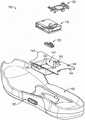
图1总体上图示了根据示例性实施方案的主动鞋类物品(active footweararticle)的部件的分解视图。1 generally illustrates an exploded view of components of an active footwear article according to an exemplary embodiment.
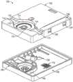
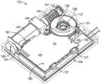
图2A至图2C总体上图示了根据一些示例性实施方案的传感器系统和机动化系带引擎。2A-2C generally illustrate a sensor system and a motorized tethering engine according to some example embodiments.
图3总体上图示了根据示例性实施方案的机动化系带系统的部件的框图。3 generally illustrates a block diagram of components of a motorized lacing system according to an exemplary embodiment.
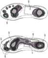
图4是图示了当鞋类物品的用户站立时鞋类物品中的标称或普通足部(nominalor average foot)(左)和高足弓足部(右)的压力分布数据的图。4 is a graph illustrating pressure distribution data for a nominal or average foot (left) and a high arch foot (right) in an article of footwear when a user of the article of footwear is standing.
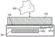
图5A和图5B总体上图示了根据示例性实施方案的鞋类物品的鞋内底中的基于电容的足部存在传感器的图。5A and 5B generally illustrate diagrams of a capacitance-based foot presence sensor in an insole of an article of footwear according to example embodiments.
图6总体上图示了根据示例性实施方案的用于足部存在检测的电容传感器系统。6 generally illustrates a capacitive sensor system for foot presence detection according to an exemplary embodiment.
图7总体上图示了根据示例性实施方案的基于电容的第一足部存在传感器的示意图。7 generally illustrates a schematic diagram of a capacitance-based first foot presence sensor according to an exemplary embodiment.
图8总体上图示了根据示例性实施方案的基于电容的第二足部存在传感器的示意图。8 generally illustrates a schematic diagram of a capacitance-based second foot presence sensor according to an exemplary embodiment.
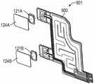
图9A、图9B和图9C总体上图示了根据一些示例性实施方案的基于电容的足部存在传感器电极的示例。9A, 9B, and 9C generally illustrate examples of capacitance-based foot presence sensor electrodes in accordance with some example embodiments.
图10图示了示出使用来自鞋类传感器的足部存在信息的示例的流程图。Figure 10 illustrates a flow chart showing an example of using foot presence information from footwear sensors.
图11图示了示出使用来自鞋类传感器的足部存在信息的第二示例的流程图。11 illustrates a flow chart showing a second example of using foot presence information from footwear sensors.
图12总体上图示了来自电容式足部存在传感器的第一时变信息的图表。12 generally illustrates a graph of first time-varying information from a capacitive foot presence sensor.
图13总体上图示了来自电容式足部存在传感器的第二时变信息的图表。13 generally illustrates a graph of second time-varying information from a capacitive foot presence sensor.
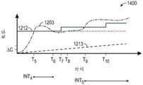
图14总体上图示了来自电容式足部存在传感器的第三时变信息的图表。14 generally illustrates a graph of third time-varying information from a capacitive foot presence sensor.
图15总体上图示了来自电容式足部存在传感器的第四时变信息的图表。15 generally illustrates a graph of fourth time-varying information from a capacitive foot presence sensor.
图16总体上图示了根据示例性实施方案的来自电容式足部存在传感器的时变信息和信号形态限度(signal morphology limit)的图表。16 generally illustrates a graph of time-varying information and signal morphology limits from capacitive foot presence sensors, according to an exemplary embodiment.
图17总体上图示了在鞋类物品的鞋底夹层中并且位于电介质堆叠(dielectricstack)下方的基于电容的足部存在传感器的图的示例。17 generally illustrates an example of a graph of a capacitance-based foot presence sensor in a midsole of an article of footwear and below a dielectric stack.
图18总体上图示了包括示出电介质填充物对来自电容式足部存在传感器的电容指示信号的影响的图表的示例。18 generally illustrates an example including a graph showing the effect of a dielectric filler on a capacitive indication signal from a capacitive foot presence sensor.
图19总体上图示了示出来自鞋类中的基于电容的足部存在传感器的电容指示第三信号的一部分的图表的示例。19 generally illustrates an example of a graph showing a portion of a third signal indicative of capacitance from a capacitance-based foot presence sensor in footwear.
详细描述Detailed Description
通过早在1989年发布的电影《回到未来II》中的Marty McFly穿用的虚构的动力系带

在示例中,模块化自动化系带鞋类平台包括固定到鞋类物品中的鞋底夹层的鞋底夹层板,该鞋底夹层板用于接纳系带引擎。鞋底夹层板的设计允许系带引擎迟至购买的时间点才被添加到鞋类平台。鞋底夹层板和模块化自动化鞋类平台的其他方面允许不同类型的系带引擎互换地使用。例如,下面讨论的机动化系带引擎可以被更改为人力系带引擎。可替代地,具有足部存在感测或其他特征的全自动机动化系带引擎可以被容纳在标准鞋底夹层板内。In an example, the modular automated lacing footwear platform includes a midsole panel secured to a midsole in the article of footwear for receiving a lacing engine. The design of the midsole panel allows the lace-up engine to be added to the footwear platform as late as the point of purchase. The midsole panel and other aspects of the modular automated footwear platform allow different types of lacing engines to be used interchangeably. For example, the motorized lacing engine discussed below can be changed to a human lacing engine. Alternatively, a fully motorized lacing engine with foot presence sensing or other features may be housed within a standard midsole panel.
本文中讨论的自动化鞋类平台可以包括鞋外底致动器接口,以向最终用户提供收紧控制以及视觉反馈,例如,使用穿过半透明的保护性鞋外底材料投射的LED灯光。致动器可以向用户提供触觉和视觉反馈,以指示系带引擎或其他自动化鞋类平台部件的状态。The automated footwear platforms discussed herein may include an outsole actuator interface to provide tightening control as well as visual feedback to the end user, eg, using LED lights projected through a translucent protective outsole material. The actuators can provide tactile and visual feedback to the user to indicate the status of the lacing engine or other automated footwear platform components.
在示例中,鞋类平台包括足部存在传感器,其被配置成检测足部何时存在于鞋中。当足部被检测到时,那么一个或更多个鞋类功能或过程可以诸如自动地以及在没有另外的用户输入或命令的情况下被启动。例如,当检测到足部适当地抵靠鞋内底安置在鞋类中时,控制电路可以自动地启动系带收紧、数据收集、鞋类诊断或其他过程。In an example, the footwear platform includes a foot presence sensor configured to detect when a foot is present in the shoe. When the foot is detected, then one or more footwear functions or processes may be initiated, such as automatically and without additional user input or command. For example, upon detecting that the foot is properly seated in the footwear against the insole, the control circuitry may automatically initiate lace-up, data collection, footwear diagnostics, or other processes.
过早地激活或启动自动化系带机构或鞋类收紧机构能够减损用户对鞋类的体验。例如,如果系带引擎在足部完全抵靠鞋内底安置之前被激活,那么用户可能难以将他或她的足部的剩余部分放入到鞋类中,或者用户可能不得不手动调整系带张力。因此,本发明人已经认识到,要解决的问题包括确定足部是否适当或完全安置在鞋类物品中,诸如其中脚趾、足底中段和足跟部分与鞋内底的对应部分适当地对齐。发明人还认识到,该问题包括使用尽可能少的传感器来精确地确定足部位置或足部定向,以致降低传感器成本和组装成本并且降低设备复杂性。Activating or activating an automated lacing mechanism or footwear tightening mechanism prematurely can detract from the user's experience with the footwear. For example, if the lacing engine is activated before the foot is fully seated against the insole, the user may have difficulty placing the remainder of his or her foot into the footwear, or the user may have to manually adjust the lacing tension. Accordingly, the inventors have recognized that the problem to be solved involves determining whether the foot is properly or fully seated in an article of footwear, such as where the toe, mid-plantar and heel portions are properly aligned with corresponding portions of the insole. The inventors have also recognized that the problem involves using as few sensors as possible to accurately determine foot position or foot orientation so as to reduce sensor and assembly costs and reduce device complexity.
对这些问题的解决方案包括在鞋类的足弓区域和/或鞋跟区域中提供传感器。在示例中,传感器是电容传感器,其被配置成感测附近电场中的改变。电场中的改变或电容改变可以当足部进入或离开鞋类时实现,包括当足部的一些部分处于距传感器比足部的其他部分更大的距离处时。在示例中,电容传感器与系带引擎外壳成一体或容纳在系带引擎外壳内。在示例中,电容传感器的至少一部分被设置在系带引擎外壳的外部,并且包括一个或更多个到外壳内部的电源或处理电路的导电互连件。Solutions to these problems include providing sensors in the arch area and/or heel area of the footwear. In an example, the sensor is a capacitive sensor configured to sense changes in a nearby electric field. Changes in the electric field or capacitance changes can be achieved when the foot enters or leaves the footwear, including when some parts of the foot are at a greater distance from the sensor than other parts of the foot. In an example, the capacitive sensor is integral with or contained within the tethered engine housing. In an example, at least a portion of the capacitive sensor is disposed outside the tethered engine housing and includes one or more conductive interconnects to power or processing circuitry inside the housing.
适于在足部存在检测中使用的电容传感器可以具有多种配置。电容传感器可以包括板电容器,其中一个板被配置成相对于另一个移动,诸如响应于施加在一个或更多个板上的压力或压力的改变。在示例中,电容传感器包括多个迹线,诸如大体上布置在平行于鞋内底的上表面或与鞋内底的上表面相重合的平面中。这样的迹线可以被空气间隙(或其他材料,诸如泡沫聚苯乙烯)横向分离,并且可以被由激励电路提供的AC驱动信号选择性地或周期性地驱动。在示例中,电极可以具有交错的梳状配置。这样的电容传感器可以提供变化的电容信号,该变化的电容信号基于电极自身相对于彼此的移动,并且基于由于足部或其他对象的存在或不存在或移动而对电极附近电场的干扰。Capacitive sensors suitable for use in foot presence detection can have a variety of configurations. Capacitive sensors may include plate capacitors, where one plate is configured to move relative to the other, such as in response to pressure or changes in pressure applied to one or more plates. In an example, the capacitive sensor includes a plurality of traces, such as disposed generally in a plane parallel to or coincident with the upper surface of the insole. Such traces may be laterally separated by an air gap (or other material, such as styrofoam), and may be selectively or periodically driven by an AC drive signal provided by an excitation circuit. In an example, the electrodes may have a staggered comb configuration. Such capacitive sensors may provide varying capacitive signals based on the movement of the electrodes themselves relative to each other and on disturbances to the electric field near the electrodes due to the presence or absence or movement of feet or other objects.
在示例中,基于电容的传感器可以比机械传感器更可靠,例如,因为基于电容的传感器不需要包括移动部件。基于电容的传感器的电极可以被耐用的电场可渗透材料涂覆或覆盖,并且因此可以保护电极免于直接暴露于环境改变、潮湿、溢出物、灰尘或其他污染物,并且人或其他材料不与传感器的电极直接接触。In an example, capacitive-based sensors may be more reliable than mechanical sensors, for example, because capacitive-based sensors need not include moving parts. The electrodes of capacitance-based sensors can be coated or covered with a durable electric field permeable material, and thus the electrodes can be protected from direct exposure to environmental changes, moisture, spills, dust or other contaminants, and from human or other materials The electrodes of the sensor are in direct contact.
在示例中,电容传感器提供模拟输出信号,该模拟输出信号指示由传感器检测到的电容幅度(a magnitude of a capacitance)或指示由传感器检测到的电容的改变。当足部存在于传感器附近时,输出信号可以具有第一值(例如,与低电容相对应),并且当足部不存在时,输出信号具有不同的第二值(例如,与高电容相对应)。In an example, the capacitive sensor provides an analog output signal indicative of a magnitude of a capacitance detected by the sensor or indicative of a change in capacitance detected by the sensor. The output signal may have a first value (eg, corresponding to a low capacitance) when the foot is present near the sensor, and a second, different value (eg, corresponding to a high capacitance) when the foot is not present ).
在示例中,当足部存在时的输出信号可以提供另外的信息。例如,电容信号中能够存在与迈步事件(step events)相关的可检测的变化。另外,电容信号中可以存在可检测的长期漂移,该长期漂移可以指示鞋部件(如鞋内底、矫正物或其他部件)中的磨损和/或剩余寿命。In an example, the output signal when the foot is present may provide additional information. For example, there can be detectable changes in the capacitive signal associated with step events. Additionally, there may be detectable long-term drift in the capacitance signal, which may be indicative of wear and/or remaining life in footwear components such as insoles, orthotics, or other components.
在示例中,电容传感器包括或耦合到电容数字转换器电路,该电容数字转换器电路被配置成提供指示由传感器感测的电容幅度的数字信号。在示例中,电容传感器包括处理器电路,该处理器电路被配置成提供中断信号或逻辑信号,该中断信号或逻辑信号指示所感测出的电容值是否满足指定的阈值电容条件。在示例中,电容传感器测量相对于基线或参考电容值的电容特性,并且基线或参考可以被更新或调整,以致适应环境改变或可以影响所感测出的电容值的其他改变。In an example, the capacitive sensor includes or is coupled to a capacitive-to-digital converter circuit configured to provide a digital signal indicative of the magnitude of the capacitance sensed by the sensor. In an example, the capacitive sensor includes a processor circuit configured to provide an interrupt signal or logic signal indicating whether the sensed capacitance value satisfies a specified threshold capacitance condition. In an example, a capacitive sensor measures capacitance characteristics relative to a baseline or reference capacitance value, and the baseline or reference may be updated or adjusted to accommodate environmental changes or other changes that may affect the sensed capacitance value.
在示例中,电容传感器在鞋的鞋内底的足弓区域或鞋跟区域附近设置在足部下方。电容传感器可以大体上是平面的或平坦的。电容传感器可以是刚性的或柔性的,并且被配置成符合足部的轮廓。在一些情况下,当鞋被穿用时,诸如可以具有相对低的介电常数或低的相对介电系数的空气间隙可以存在于电容传感器的一部分和足部之间。诸如可以具有相对高的介电常数或比空气更大的相对介电系数的间隙填充物可以被设置在电容传感器上方,以便桥接电容传感器和足部表面之间的任何空间。间隙填充物可以是可压缩的或不可压缩的。在示例中,间隙填充物被选择以提供介电值和在鞋类中使用的适合性之间的合适的折衷,以便提供具有足够的灵敏度和足部下方的用户舒适度的传感器。In an example, the capacitive sensor is positioned under the foot near the arch area or heel area of the insole of the shoe. Capacitive sensors may be substantially planar or flat. Capacitive sensors can be rigid or flexible and configured to conform to the contours of the foot. In some cases, an air gap, such as may have a relatively low dielectric constant or a low relative dielectric constant, may exist between a portion of the capacitive sensor and the foot when the shoe is worn. A gap filler such as, which may have a relatively high dielectric constant or a relative dielectric constant greater than air, may be placed over the capacitive sensor to bridge any space between the capacitive sensor and the surface of the foot. Gap fillers can be compressible or incompressible. In an example, the gap filler is selected to provide a suitable compromise between dielectric value and suitability for use in footwear in order to provide a sensor with sufficient sensitivity and user comfort under the foot.
下面讨论自动化鞋类平台的多种部件,包括机动化系带引擎、足部存在传感器、鞋底夹层板以及平台的多种其他部件。虽然本公开的大部分集中于作为用于机动化系带引擎的触发的足部存在感测,但是所讨论的设计的许多方面可应用于人力系带引擎,或者可以与足部存在传感器连接的其他电路或特征,以致使其他鞋类功能如数据收集或生理监测自动化。诸如在“自动化鞋类平台”中使用的术语“自动化”并不旨在仅覆盖在没有指定用户输入的情况下操作的系统。相反,术语“自动化鞋类平台”可以包括多种电动和人力、自动地激活和人为地激活的机构,以用于收紧鞋类的系带或保持系统或者用于控制主动鞋类的其他方面。Various components of the automated footwear platform are discussed below, including the motorized lacing engine, foot presence sensor, midsole panel, and various other components of the platform. While much of this disclosure focuses on foot presence sensing as a trigger for motorized lace engines, many aspects of the designs discussed are applicable to human-powered lace engines, or can be connected to foot presence sensors Other circuits or features to automate other footwear functions such as data collection or physiological monitoring. The term "automation" as used in "Automated Footwear Platform" is not intended to cover only systems that operate without specified user input. Conversely, the term "automated footwear platform" may include a variety of electrical and human, automatically activated and manually activated mechanisms for tightening lacing or retention systems of footwear or for controlling other aspects of active footwear .
图1总体上图示了根据示例性实施方案的主动鞋类物品的部件的分解视图。图1的示例包括具有系带引擎110、盖子120、致动器130、鞋底夹层板140、鞋底夹层155和鞋外底165的机动化系带系统100。系带引擎110可以包括系统100中的用户可替换部件,并且可以包括或者可以耦合到一个或更多个足部存在传感器。在示例中,系带引擎110包括电容式足部存在传感器,或者耦合到电容式足部存在传感器。未在图1的示例中示出的电容式足部存在传感器可以包括布置在系带引擎110的面向足部的侧面上的多个电极。在示例中,电容式足部存在传感器的电极可以容纳在系带引擎110内,可以与系带引擎110的壳体成一体,或者可以设置在系带引擎110附近的其他地方并且使用一个或更多个电导体耦合到系带引擎110的内部的电源或处理电路。1 generally illustrates an exploded view of components of an active article of footwear according to an exemplary embodiment. The example of FIG. 1 includes a
组装图1的示例中的机动化系带系统100从将鞋底夹层板140固定在鞋底夹层155内开始。接下来,致动器130可以插入到鞋底夹层板140的外侧部中的开口中,诸如与可以嵌入在鞋外底165中的接口按钮相对。接下来,系带引擎110可以插入到鞋底夹层板140中。在示例中,系带引擎110可以与设置在鞋类中其他地方的一个或更多个传感器耦合。可以类似地执行其他组装方法以构造机动化系带系统100。Assembly of the
在示例中,系带系统100被插入在系带缆线的连续环下方,并且系带缆线与系带引擎110中的线轴对齐。为了完成组装,盖子120可以插入到鞋底夹层板140中的固定装置中、固定到闭合位置中并且锁定到鞋底夹层板140中的凹部中。盖子120可以捕获系带引擎110,并且可以在操作期间帮助维持系带缆线的对齐。In an example, the
鞋底夹层板140包括系带引擎腔141、内侧和外侧系带引导件142、前凸缘143、后凸缘144、上(顶)和下(底)表面以及致动器切口145。系带引擎腔141被配置成接纳系带引擎110。在这个示例中,系带引擎腔141在横向和前/后方向上保持系带引擎110,但是不包括将系带引擎110锁定到腔141中的特征。可选地,系带引擎腔141包括沿着一个或更多个侧壁的棘爪、突片或其他机械特征,以更可靠地将系带引擎110保持在系带引擎腔141内。
系带引导件142可以帮助将系带缆线引导到具有系带引擎110的位置中。系带引导件142可以包括倒角边缘和向下板条式斜面,以帮助将系带缆线引导到相对于系带引擎110的期望位置中。在这个示例中,系带引导件142包括鞋底夹层板140的侧面中的开口,该开口比典型的系带缆线直径宽许多倍,然而可以使用其他尺寸。
在图1的示例中,鞋底夹层板140包括在鞋底夹层板140的内侧部上进一步延伸的被塑造的或有轮廓的前凸缘143。示例性前凸缘143被设计成在鞋类平台的足弓下方提供额外的支撑。然而,在其他示例中,前凸缘143在内侧部上可能不太明显。在这个示例中,后凸缘144包括在内侧部和外侧部两者上都具有延伸部分的轮廓。图示的后凸缘144可以为系带引擎110提供增强的横向稳定性。In the example of FIG. 1 ,
在示例中,一个或更多个电极可以嵌入在鞋底夹层板140中或设置在鞋底夹层板140上,并且可以形成足部存在传感器的一部分,诸如电容式足部存在传感器的一部分。在示例中,系带引擎110包括电耦合到鞋底夹层板140上的一个或更多个电极的传感器电路。传感器电路可以被配置成使用从电极感测的电场或电容信息以确定足部是否存在或不存在于邻近于鞋底夹层板140的区域中。在示例中,电极从前凸缘143的最前边缘延伸到后凸缘144的最后边缘,并且在其他示例中,电极仅在凸缘中的一个或两个的部分上延伸。In an example, one or more electrodes may be embedded in or disposed on
在示例中,鞋类或机动化系带系统100包括一个或更多个传感器或与一个或更多个传感器连接,该一个或更多个传感器可以监测或确定足部存在于鞋类中、足部不存在于鞋类或鞋类内的足部位置特性。基于来自一个或更多个这样的足部存在传感器的信息,包括机动化系带系统100的鞋类可以被配置成执行多种功能。例如,足部存在传感器可以被配置成提供关于足部是存在于还是不存在于鞋类中的二进制信息。在示例中,耦合到足部存在传感器的处理器电路接收并解释数字或模拟信号信息,并且提供关于足部是存在于还是不存在于鞋类中的二进制信息。如果来自足部存在传感器的二进制信号指示足部存在,那么机动化系带系统100中的系带引擎110可以被激活,以致自动地增加或减少系带缆线或其他鞋类收缩装置上的张力,以致收紧或放松足部周围的鞋类。在示例中,系带引擎110或鞋类物品的其他部分包括处理器电路,该处理器电路可以接收或解译来自足部存在传感器的信号。In an example, the footwear or
在示例中,足部存在传感器可以被配置成在足部进入鞋类时提供关于足部的位置的信息。机动化系带系统100通常可以被激活,以致仅当足部被适当地定位或安置在鞋类中(诸如抵靠着鞋类物品的鞋内底的全部或一部分)时才收紧系带缆线。感测关于足部行进或位置的信息的足部存在传感器可以提供关于足部诸如相对于鞋内底或相对于鞋类物品的一些其他特征是被完全还是部分安置的信息。自动化系带程序可以被中断或延迟,直到来自传感器的信息指示足部处于合适的位置。In an example, the foot presence sensor may be configured to provide information about the position of the foot when the foot enters the footwear.
在示例中,足部存在传感器可以被配置成提供关于足部在鞋类内部的相对位置的信息。例如,足部存在传感器可以被配置成诸如通过确定足部的足弓、足跟、脚趾或其他部位中的一个或更多个诸如相对于鞋类的被配置成接纳这些足部部位的对应部分的相对位置,来感测鞋类对于给定的足部是否是好的“配合”。在示例中,足部存在传感器可以被配置成感测足部或足部部位的位置是否随着时间相对于指定的或先前记录的参考位置而改变,诸如由于系带缆线随着时间而松开或者由于足部本身的自然膨胀和收缩。In an example, the foot presence sensor may be configured to provide information regarding the relative position of the foot within the footwear. For example, a foot presence sensor may be configured, such as by determining one or more of an arch, heel, toe, or other parts of the foot, such as with respect to corresponding portions of the footwear that are configured to receive these foot parts to sense whether the footwear is a good "fit" for a given foot. In an example, the foot presence sensor may be configured to sense whether the position of the foot or foot part has changed over time relative to a designated or previously recorded reference position, such as due to lacing cables loosening over time open or due to the natural expansion and contraction of the foot itself.
在示例中,足部存在传感器可以包括电、磁、热、电容、压力、光学或其他传感器设备,其可以被配置成感测或接收关于主体的存在的信息。例如,电传感器可以包括阻抗传感器,该阻抗传感器被配置成测量至少两个电极之间的阻抗特性。当主体(诸如足部)接近于电极或邻近于电极定位时,电传感器可以提供具有第一值的传感器信号,并且当主体远离电极定位时,电传感器可以提供具有不同的第二值的传感器信号。例如,第一阻抗值可以与空的鞋类状况相关联,并且较小的第二阻抗值可以与被占用的鞋类状况相关联。In an example, a foot presence sensor may comprise an electrical, magnetic, thermal, capacitive, pressure, optical or other sensor device that may be configured to sense or receive information about the presence of the subject. For example, the electrical sensor may include an impedance sensor configured to measure an impedance characteristic between at least two electrodes. The electrical sensor may provide a sensor signal having a first value when the body (such as a foot) is positioned proximate or adjacent to the electrode, and may provide a sensor signal having a second, different value when the body is positioned away from the electrode . For example, a first impedance value may be associated with an empty footwear condition, and a second, smaller impedance value may be associated with an occupied footwear condition.
电传感器可以包括AC信号发生器电路和天线,该天线被配置成发射或接收高频信号信息,诸如包括射频信息。基于主体相对于天线的接近度,可以接收和分析一个或更多个电信号特性(诸如阻抗、频率或信号振幅),以确定主体是否存在。在示例中,接收信号强度指示(RSSI)提供关于所接收的无线电信号中的功率水平的信息。RSSI中(诸如相对于某个基线或参考值)的改变可以用于识别主体的存在或不存在。在示例中,WiFi频率可以被使用,例如在2.4GHz、3.6GHz、4.9GHz、5GHz和5.9GHz频带中的一个或更多个中。在示例中,千赫范围中的频率可以被使用,例如,大约400kHz。在示例中,功率信号改变可以在毫瓦或微瓦范围中被检测。The electrical sensor may include an AC signal generator circuit and an antenna configured to transmit or receive high frequency signal information, such as including radio frequency information. Based on the proximity of the subject relative to the antenna, one or more electrical signal characteristics (such as impedance, frequency, or signal amplitude) may be received and analyzed to determine the presence or absence of the subject. In an example, a received signal strength indication (RSSI) provides information about the power level in the received radio signal. Changes in RSSI (such as relative to some baseline or reference value) can be used to identify the presence or absence of a subject. In an example, WiFi frequencies may be used, such as in one or more of the 2.4GHz, 3.6GHz, 4.9GHz, 5GHz, and 5.9GHz frequency bands. In an example, frequencies in the kilohertz range may be used, eg, about 400 kHz. In an example, power signal changes may be detected in the milliwatt or microwatt range.
足部存在传感器可以包括磁传感器。第一磁传感器可以包括磁体和磁力计。在示例中,磁力计可以被定位在系带引擎110中或系带引擎110附近。磁体可以远离系带引擎110定位,诸如在次级鞋底或鞋内底中,该次级鞋底或鞋内底被构造成被穿用在鞋外底165上方。在示例中,磁体被嵌入在泡沫或次级鞋底的另一种可压缩材料中。当用户按压次级鞋底时,诸如当站立或行走时,磁体相对于磁力计的位置中的对应改变可以被感测和通过传感器信号被报告。The foot presence sensor may include a magnetic sensor. The first magnetic sensor may include a magnet and a magnetometer. In an example, the magnetometer may be positioned in or near the
第二磁传感器可以包括磁场传感器,该磁场传感器被配置成感测磁场中的改变或中断(例如,经由霍尔效应)。当主体接近于第二磁传感器时,传感器可以产生指示环境磁场改变的信号。例如,第二磁传感器可以包括霍尔效应传感器,该霍尔效应传感器响应于所检测出的磁场的变化而改变电压输出信号。输出信号处的电压改变可以是由于在电信号导体上产生的电压差,诸如横向于导体中的电流和垂直于电流的磁场。The second magnetic sensor may include a magnetic field sensor configured to sense changes or interruptions in the magnetic field (eg, via the Hall effect). When the subject is in proximity to the second magnetic sensor, the sensor may generate a signal indicative of a change in the ambient magnetic field. For example, the second magnetic sensor may comprise a Hall effect sensor that changes a voltage output signal in response to a detected change in the magnetic field. The voltage change at the output signal may be due to a voltage difference developed across the electrical signal conductor, such as a magnetic field transverse to the current in the conductor and perpendicular to the current.
在示例中,第二磁传感器被配置成从主体接收电磁场信号。例如,Varshavsky等人在标题为“Devices,systems and methods for security using magnetic field basedidentification”的美国专利第8,752,200号中教导了使用主体的独特电磁签名以用于认证。在示例中,鞋类物品中的磁传感器可以用于通过所检测出的电磁签名来认证或验证当前用户是鞋的所有者,并且该物品应该自动地系带,诸如根据所有者的一个或更多个指定的系带偏好(例如,收紧轮廓)。In an example, the second magnetic sensor is configured to receive an electromagnetic field signal from the subject. For example, Varshavsky et al., in US Patent No. 8,752,200, entitled "Devices, systems and methods for security using magnetic field based identification," teach the use of a subject's unique electromagnetic signature for authentication. In an example, a magnetic sensor in an item of footwear may be used to authenticate or verify through the detected electromagnetic signature that the current user is the owner of the shoe and that the item should be automatically strapped, such as according to one or more of the owner's Multiple specified lace-up preferences (eg, tightened contours).
在示例中,足部存在传感器包括热传感器,该热传感器被配置成感测鞋类的一部分中或附近的温度上的改变。当穿用者的足部进入鞋类物品时,当穿用者自身的体温不同于鞋类物品的环境温度时,物品的内部温度改变。因此,热传感器可以基于温度改变提供足部可能存在或不存在的指示。In an example, the foot presence sensor includes a thermal sensor configured to sense a change in temperature in or near a portion of the footwear. When the wearer's foot enters the article of footwear, the internal temperature of the article changes when the wearer's own body temperature differs from the ambient temperature of the article of footwear. Thus, the thermal sensor can provide an indication that the foot may or may not be present based on temperature changes.
在示例中,足部存在传感器包括电容传感器,该电容传感器被配置成感测电容的变化。电容传感器可以包括单板或电极,或者电容传感器可以包括多板或多电极配置。在本文中进一步描述了电容型足部存在传感器的多种示例。In an example, the foot presence sensor includes a capacitive sensor configured to sense changes in capacitance. Capacitive sensors may include a single plate or electrode, or capacitive sensors may include a multi-plate or multi-electrode configuration. Various examples of capacitive foot presence sensors are further described herein.
在示例中,足部存在传感器包括光学传感器。光学传感器可以被配置成确定视线是否被中断,诸如在鞋类腔的相对的侧面之间。在示例中,光学传感器包括光传感器,当足部插入到鞋类中时,该光传感器可以被足部覆盖。当传感器指示感测的光或亮度状况上的改变时,可以提供足部存在或位置的指示。In an example, the foot presence sensor includes an optical sensor. The optical sensor may be configured to determine if the line of sight is interrupted, such as between opposing sides of the footwear cavity. In an example, the optical sensor includes a light sensor that can be covered by the foot when the foot is inserted into the footwear. When the sensor indicates a change in sensed light or brightness conditions, an indication of the presence or position of the foot may be provided.
在本文中讨论的任何不同类型的足部存在传感器可以独立使用,或者来自两个或更多个不同的传感器或传感器类型的信息可以一起使用,以提供关于足部存在、不存在、定向、与鞋类的适配性的更多信息或者关于足部和/或其与鞋类的关系的其他信息。Any of the different types of foot presence sensors discussed herein can be used independently, or information from two or more different sensors or sensor types can be used together to provide information on foot presence, absence, orientation, and More information on the fit of the footwear or other information about the foot and/or its relationship to the footwear.
图2A至图2C总体上图示了根据一些示例性实施方案的传感器系统和机动化系带引擎。图2A介绍了示例性系带引擎110的多种外部特征,包括壳体结构150、壳螺钉108、系带通道112(也称为系带引导缺口112)、系带通道过渡部114、线轴凹部115、按钮开口122、按钮121、按钮膜密封件124、编程座部128、线轴131和线轴131中的系带凹槽132。其他设计可以类似地被使用。例如,其他开关类型可以被使用,诸如密封的圆顶开关、或者膜密封件124可以被消除,等。在示例中,系带引擎110可以包括一个或更多个互连件或电接触件,用于将系带引擎110内部的电路与系带引擎110的外部的电路,诸如外部足部存在传感器(或其部件)、如开关或按钮的外部致动器或其他设备或部件连接。2A-2C generally illustrate a sensor system and a motorized tethering engine according to some example embodiments. 2A illustrates various external features of the
系带引擎110可以通过一个或更多个螺钉(诸如壳螺钉108)保持在一起。壳螺钉108可以定位在主驱动机构附近,以增强系带引擎110的结构完整性。壳螺钉108还起到帮助组装过程的作用,诸如将壳体结构150保持在一起用于外部接缝的超声波焊接。The
在图2A的示例中,系带引擎110包括系带通道112,一旦引擎被组装到自动化鞋类平台中,系带通道112接纳系带或系带缆线。系带通道112可以包括具有倒角边缘的通道壁,以提供平滑引导表面,系带缆线可在操作期间抵靠该引导表面或在该引导表面内行进。系带通道112的平滑引导表面的部分可以包括通道过渡部114,该通道过渡部114可以是系带通道112的通向线轴凹部115的加宽部分。线轴凹部115从通道过渡部114过渡到与线轴131的轮廓紧密符合的大致圆形部分。线轴凹部115可以帮助保持缠绕的系带缆线,以及保持线轴131的位置。该设计的其他方面可以提供保持线轴131的其他手段。在图2A的示例中,线轴131成形为类似于溜溜球的一半,具有贯穿平坦顶表面的系带凹槽132和从相对侧面向下延伸的线轴轴杆(图2A中未示出)。In the example of FIG. 2A, lacing
系带引擎110的外侧部包括容纳按钮121的按钮开口122,按钮121可以被配置成激活或调整自动化鞋类平台的一个或更多个特征。按钮121可以提供外部接口,用于激活被包括在系带引擎110中的多种开关。在一些示例中,壳体结构150包括按钮膜密封件124,以提供保护免于灰尘和水。在这个示例中,按钮膜密封件124是高达几密耳(千分之一英寸)厚的透明塑料(或类似材料),其可以从壳体结构150的上表面粘附,诸如在拐角上方和外侧部下面。在另一示例中,按钮膜密封件124是覆盖按钮121和按钮开口122的近似2密耳厚的乙烯基粘合剂背衬膜。其他类型的按钮和密封剂可以被类似地使用。The outboard portion of lacing
图2B是包括顶部部分102和底部部分104的壳体结构150的图示。在这个示例中,顶部部分102包括诸如壳螺钉108、系带通道112、系带通道过渡部114、线轴凹部115、按钮开口122和按钮密封凹部126的特征。在示例中,按钮密封凹部126是顶部部分102的被切除以为按钮膜密封件124提供插入部的一部分。FIG. 2B is an illustration of
在图2B的示例中,底部部分104包括诸如无线充电器入口105、接合部106和脂膏隔离壁109的特征。还图示但未具体指明的是用于接纳壳螺钉108的壳螺钉基座,以及脂膏隔离壁109内用于保持驱动机构的部分的多种特征。脂膏隔离壁109被设计成将脂膏或驱动机构周围的类似化合物保持远离系带引擎110的多种电气部件。In the example of FIG. 2B ,
壳体结构150可以在顶部部分102和底部部分104中的一个或两个中包括嵌入在结构表面中或施加在结构表面上的一个或更多个电极170。图2B的示例中的电极170被示出耦合到底部部分104。在示例中,电极170包括基于电容的足部存在传感器电路(例如,参见本文中讨论的足部存在传感器310)的一部分。另外地或可替代地,电极170可以耦合到顶部部分102。耦合到顶部部分102或底部部分104的电极170可以用于无线功率传输和/或作为基于电容的足部存在传感器电路的一部分。在示例中,电极170包括设置在壳体结构150的外表面上的一个或更多个部分,并且在另一示例中,电极170包括设置在壳体结构150的内侧表面上的一个或更多个部分。The
图2C是根据示例性实施方案的系带引擎110的多个内部部件的图示。在这个示例中,系带引擎110还包括线轴磁体136、O形环密封件138、蜗杆传动件140、套管141、蜗杆传动键、齿轮箱148、齿轮马达145、马达编码器146、马达电路板147、蜗杆齿轮151、电路板160、马达座部161、电池连接部162和有线充电座部163。线轴磁体136通过磁力计(图2C中未示出)的检测来帮助跟踪线轴131的运动。O形环密封件138起到杜绝可能围绕线轴轴杆移动到系带引擎110中的灰尘和湿气的作用。电路板160可以包括一个或更多个用于诸如下面描述的电容式足部存在传感器310的足部存在传感器的接口或互连件。在示例中,电路板160包括提供足部存在传感器310的一部分的一个或更多个迹线或导电平面。FIG. 2C is an illustration of various internal components of the
在这个示例中,系带引擎110的主要驱动部件包括蜗杆传动件140、蜗杆齿轮151、齿轮马达145和齿轮箱148。蜗杆齿轮151被设计成抑制蜗杆传动件140和齿轮马达145的反向传动,这意味着经由线轴131从系带缆线进入的主要输入力可以在相对大的蜗杆齿轮和蜗杆传动齿上得到分解。这种布置以免齿轮箱148需要包括足够强度的齿轮,以承受来自鞋类平台的主动使用的动态加载或来自收紧系带系统的收紧加载两者。蜗杆传动件140包括帮助保护驱动系统的多个脆弱部分的额外的特征,诸如蜗杆传动键。在这个示例中,蜗杆传动键是蜗杆传动件140的马达端部中的径向狭槽,该径向狭槽通过从齿轮箱148出来的传动轴杆与销接合。这种布置通过允许蜗杆传动件140在轴向方向上自由移动(远离齿轮箱148)、将那些轴向负荷传递到套管141和壳体结构150上来防止蜗杆传动件140在齿轮箱148或齿轮马达145上施加不适当的轴向力。In this example, the main drive components of
图3总体上图示了根据示例性实施方案的机动化系带系统300的部件的框图。系统300包括机动化系带系统的一些但不一定是所有的部件,诸如包括接口按钮301、电容式足部存在传感器310和壳体结构150,该壳体结构150封装具有处理器电路320的印刷电路板组件(PCA)、电池321、充电线圈322、编码器325、运动传感器324和驱动机构340。除了其他方面外,驱动机构340可以包括马达341、传动装置342和系带线轴343。除了其他方面外,运动传感器324可以包括单轴或多轴加速度计、磁力计、陀螺仪或被配置成感测壳体结构150的运动或壳体结构150内或耦合到壳体结构150的一个或更多个部件的运动的其他传感器或设备。FIG. 3 generally illustrates a block diagram of the components of a
在图3的示例中,处理器电路320与接口按钮301、足部存在传感器310、电池321、充电线圈322和驱动机构340中的一个或更多个进行数据或功率信号通信。传动装置342将马达341联接到线轴343以形成驱动机构340。在图3的示例中,按钮301、足部存在传感器310和环境传感器350被示出在壳体结构150的外部或部分地在壳体结构150的外部。In the example of FIG. 3 ,
在可替代实施方案中,按钮301、足部存在传感器310和环境传感器350中的一个或更多个可以被封装在壳体结构150中。在示例中,足部存在传感器310被设置在壳体结构150的内部,以保护传感器免受汗液和灰尘或碎屑的侵害。最小化或消除穿过壳体结构150的壁的连接可以帮助增加组件的耐用性和可靠性。In alternative embodiments, one or more of
在示例中,处理器电路320控制驱动机构340的一个或更多个方面。例如,处理器电路320可以被配置成从按钮301和/或从足部存在传感器310和/或从运动传感器324接收信息,并且作为响应而控制驱动机构340,以致围绕足部收紧或松开鞋类。在示例中,处理器电路320另外地或可替代地被配置成发出命令,以从足部存在传感器310或其他传感器获取或记录传感器信息,以及其他功能。在示例中,处理器电路320借助使用足部存在传感器310检测足部存在、使用足部存在传感器310检测足部定向或位置、或者使用运动传感器324检测指定的姿势中的一个或更多个决定驱动机构340的操作。In an example,
在示例中,系统300包括环境传感器350。来自环境传感器350的信息可以用于更新或调整用于足部存在传感器310的基线或参考值。如下面进一步解释的,诸如响应于传感器附近的环境条件,由电容式足部存在传感器测量的电容值可以随时间变化。因此,使用来自环境传感器350的信息,处理器电路320和/或足部存在传感器310可以被配置成更新或调整测量或感测的电容值。In an example,
图4是图示了当鞋类物品的用户站立时,鞋类物品400中的标称或普通足部(左)和用于高足弓足部(右)的压力分布数据的图。在这个示例中,可以看到的是,足下相对较大的压力区包括在足跟区域401处、在前脚掌区域402(例如,在足弓和脚趾之间)处和在拇趾区域403(例如,“大脚趾”区域)处。然而,如以上讨论的,将多种主动部件(例如,包括足部存在传感器310)包括在中央区域(诸如在足弓区域处或附近)中会是有利的。在示例中,在足弓区域中,当包括壳体结构150的鞋类物品被穿用时,壳体结构150对用户来说可以通常是不太引人注意或不太侵扰的。4 is a graph illustrating pressure distribution data for a nominal or normal foot (left) and for a high arch foot (right) in article of
在图4的示例中,系带引擎腔141可以设置在足弓区域中。与足部存在传感器310相对应的一个或更多个电极可以定位在第一位置405处或附近。取决于足部相对于第一位置405的接近度,使用定位在第一位置405处的电极测量的电容值可以是不同的。例如,对于平均足部和高足弓足部不同的电容值将被获得,因为足部本身的表面存在于离第一位置405不同的距离处。在示例中,足部存在传感器310和/或系带引擎110的位置可以相对于鞋类进行调整(例如,由用户或由在销售点处的技术人员),以致适应不同用户的不同足部特性并且增强从足部存在传感器310获得的信号质量。在示例中,足部存在传感器310的灵敏度可以被调整,诸如通过增加驱动信号电平或者通过改变定位在足部存在传感器310和足部之间的电介质材料。In the example of FIG. 4, the lace-up
图5A和图5B总体上图示了根据示例性实施方案的鞋类物品的鞋内底中的基于电容的足部存在传感器的图。当包含基于电容的足部存在传感器的物品被穿用时,该传感器可以设置在对象或主体550(诸如足部)的表面下方。5A and 5B generally illustrate diagrams of a capacitance-based foot presence sensor in an insole of an article of footwear according to example embodiments. When an article containing a capacitance-based foot presence sensor is worn, the sensor may be positioned below the surface of an object or
在图5A中,基于电容的足部存在传感器可以包括耦合到电容感测控制器电路502的第一电极组件501A。在示例中,控制器电路502被包括在处理器电路320中或包括由处理器电路320执行的功能。在图5A的示例中,第一电极组件501A和/或控制器电路502可以被包括在壳体结构150的内部部分中或安装到壳体结构150的内部部分,或者可以耦合到壳体结构150的内部的PCA。在示例中,第一电极组件501A可以设置在壳体结构150的面向足部的表面处或邻近于壳体结构150的面向足部的表面设置。在示例中,第一电极组件501A包括跨过壳体结构150的内部的上表面区域分布的多个迹线。In FIG. 5A , the capacitance-based foot presence sensor may include a
在图5B中,基于电容的足部存在传感器可以包括耦合到电容感测控制器电路502的第二电极组件501B。第二电极组件501B可以安装到壳体结构150的外部部分或壳体结构150的外部部分的附近,并且可以电耦合到壳体结构150的内部的PCA,诸如使用柔性连接器511。在示例中,第二电极组件501B可以设置在壳体结构150的面向足部的表面处或邻近于壳体结构150的面向足部的表面设置。在示例中,第二电极组件501B包括柔性电路,该柔性电路固定到壳体结构150的内表面或外表面,并且经由一个或更多个导体耦合到处理器电路320。In FIG. 5B , the capacitance-based foot presence sensor may include a
在示例中,控制器电路502包括爱特梅尔(Atmel)的ATSAML21E18B-MU、意法半导体(ST Microelectronics)的STM32L476M或其他类似设备。除了其他方面之外,如下面更详细解释的,控制器电路502可以被配置成向第一电极组件502A或第二电极组件501B中的至少一对电极提供AC驱动信号,并且作为响应,基于对象或主体550对该对电极的接近度的对应的改变来感测电场的改变。在示例中,控制器电路502包括或使用足部存在传感器310或处理器电路320。In an example, the
可以在电极组件501和待被感测的对象或主体550之间提供多种材料。例如,电极间绝缘、壳体结构150的材料、鞋内底材料、插入材料510、袜子或其他足部覆盖物、主体贴布、肌内效贴布(kinesiology tape)、或者可以插入主体550和电极组件501之间,以致改变鞋类的介电特性,从而影响包括或使用电极组件501的传感器的电容检测灵敏度的其他材料。控制器电路502可以被配置成基于插入材料的数量或类型来更新或调整激励或感测参数,以致增强使用电极组件501感测出的电容值的灵敏度或信噪比。Various materials may be provided between the electrode assembly 501 and the object or
在图5A-5B的示例中,第一电极组件501A和/或第二电极组件501B可以由控制器电路502中的信号发生器激励,并且因而电场可以从电极组件的面向足部的顶侧面投射。在示例中,电极组件下方的电场可以至少部分地使用定位在感测电极下方的驱动屏蔽件来阻挡。驱动屏蔽件和电极组件可以彼此电绝缘。例如,如果第一电极组件501A在PCA的一个表面上,那么驱动屏蔽件可以在PCA的底层上,或者在多层PCA上的多个内层中的任何一个上。在示例中,驱动屏蔽件可以具有等于或大于第一电极组件501A的表面积,并且可以被居中地置于第一电极组件501A正下方。驱动屏蔽件可以接收驱动信号,并且作为响应,产生与由第一电极组件501A产生的场的X轴分支(X axis leg)的极性、相位和/或振幅相同的电场。驱动屏蔽件的场可以排斥第一电极组件501A的电场,从而将传感器场与多种寄生效应隔离,诸如不期望耦合到PCA的接地面。驱动屏蔽件可以被类似地提供用于与第二电极组件501B一起使用。例如,如图5B的示例中所示出的,第二电极组件501B可以设置在壳体结构150上方,并且壳体结构150的一部分可以包括用作驱动屏蔽件的导电薄膜。另外地或可替代地,当第二电极组件501B设置在除了壳体结构150的顶上之外的位置处时,驱动屏蔽件可以设置在鞋类物品中的其他位置。In the example of Figures 5A-5B, the
将壳体结构150定位在其中的优选位置是在鞋类的足弓区中,因为它是不太可能被穿用者感觉到的区,并且不太可能引起穿用者的不舒适。使用电容感测用于检测鞋类中的足部存在的一个优点包括:即使当电容传感器放置在足弓区域中并且用户具有相对或异常高的足部足弓时,电容传感器也可以良好地运行。例如,传感器驱动信号振幅或形态特性可以基于从电容传感器接收的信号的检测出的信噪比来改变或选择。在示例中,传感器驱动信号可以在每次鞋类被使用时被更新或调整,以致适应设置在第一电极组件501A或第二电极组件501B与主体550之间的一种或更多种材料(例如,袜子、鞋内底等)上的改变。The preferred location in which the
在示例中,电容传感器的电极组件,诸如第一电极组件501A或第二电极组件501B,可以被配置成感测多个电极之间(诸如X轴和Y轴定向的电极之间)的在信号方面的差异。在示例中,合适的采样频率可以在大约2Hz和50Hz之间。在一些示例中,基于电容的足部感测技术对鞋内底上或足部周围的袜子中的汗液(湿度)来说可以是相对不变的。这样的湿气的影响可以是减小检测的动态范围,因为湿气的存在可以增加测量的电容。然而,在一些示例中,动态范围足以在鞋类中的湿气的预期水平内适应这种效果。In an example, an electrode assembly of a capacitive sensor, such as the
图6总体上图示了根据示例性实施方案的用于足部存在检测的电容传感器系统600。系统600包括主体550(例如,表示主动鞋类物品中或附近的足部)以及第一电极601和第二电极602。电极601和602可以形成来自图5A-5B的示例的第一电极组件501A或第二电极组件501B的全部或一部分,诸如包括足部存在传感器310的一部分。在图6的示例中,第一电极601和第二电极602被图示为相对于彼此和主体550竖直地间隔开,然而,例如,如图7至图9C的示例中详细描述的,电极可以类似地水平间隔开。也就是说,在示例中,电极可以设置在平行于主体550的下表面的平面中。在图6的示例中,第一电极601被配置作为发射电极并且耦合到信号发生器610。在示例中,信号发生器610包括来自图3的示例的处理器电路320的一部分。也就是说,处理器电路320可以被配置成生成驱动信号并将其施加到第一电极601。FIG. 6 generally illustrates a
作为利用来自信号发生器610的驱动信号激励第一电极601的结果,电场615可以主要产生在第一电极601和第二电极602之间。也就是说,产生的电场615的多个分量可以在第一电极601和第二电极602之间延伸,并且产生的电场615的其他边缘分量可以在其他方向上延伸。例如,边缘分量可以从发射器电极或第一电极601远离壳体结构150延伸(图6的示例中未描绘),并且向后终止在接收器电极或第二电极602处。As a result of exciting the
关于电场615的信息(包括关于由于主体550的接近度的电场615中的改变的信息)可以被第二电极602感测或接收。从第二电极602感测的信号可以使用多种电路来处理,并且用于提供指示主体550存在或不存在的模拟或数字信号。Information about the
例如,由第二电极602接收的电场615的场强可以使用被配置成将模拟电容指示信号转换成数字信号的Σ-Δ(sigma-delta)模拟-数字转换器电路(ADC)620来测量。当诸如主体550的对象侵入电场615(包括其边缘分量)时,电极附近的电环境改变。当主体550进入场时,电场615的一部分被分流到地面,而不是在第二电极602处被接收和终止,或者在第二电极602处接收之前穿过主体550(例如,而不是穿过空气)。这可以导致电容改变,该电容改变可以由足部存在传感器310和/或由处理器电路320检测。For example, the field strength of the
在示例中,第二电极602可以大体上连续地接收电场信息,并且该信息可以由ADC620连续地或周期性地采样。来自ADC 620的信息可以根据偏移621而被处理或更新,然后数字输出信号622可以被提供。在示例中,偏移621是电容偏移,其可以被指定或编程(例如,在处理器电路320的内部),或者可以基于用于跟踪环境随时间、温度和环境的其他可变特性的改变的另一个电容器。In an example, the
在示例中,数字输出信号622可以包括关于主体550的诸如通过将测量的电容值与指定的阈值进行比较确定的存在或不存在的二进制信息。在示例中,数字输出信号622包括关于测量的电容的定性信息,诸如可以用于(例如,由处理器电路320)提供主体550存在或不存在的可能性的指示。In an example,
周期性地,或者每当足部存在传感器310未激活时(例如,如使用来自运动传感器324的信息确定的),电容值可以被测量并存储为参考值、基线值或环境值。当足部或主体接近于足部存在传感器310以及第一电极601和第二电极602时,所测量出的电容可以诸如相对于存储的参考值减小或增加。在示例中,一个或更多个阈值电容水平可以存储在例如具有处理器电路320的片上寄存器中。当测量的电容值超过指定的阈值时,那么可以确定主体550存在于(或不存在于)包含足部存在传感器310的鞋类中。Periodically, or whenever the
足部存在传感器310以及包括足部存在传感器310的一部分的电极601和602可以采取多种不同的形式,如下面几个非限制性示例中所图示的。在示例中,足部存在传感器310被配置成感测或使用关于多个电极或板之中或之间的互电容(mutual capacitance)的信息。
在示例中,电极601和602布置在电极网格中。使用网格的电容传感器可以在网格的每个行和每个列的每个交叉点处包括可变电容器。可选地,电极网格包括以一个或多个行或列布置的电极。电压信号可以施加到行或列,并且传感器的表面附近的主体或足部可以影响局部电场,并且转而可以减小互电容效应。在示例中,网格上多个点处的电容改变可以被测量以确定主体位置,诸如通过测量每个轴上的电压。在示例中,互电容测量技术可以同时提供来自网格周围多个位置的信息。In the example,
在示例中,互电容测量使用发射和接收电极的正交网格。在这样的基于网格的传感器系统中,可以针对多个离散X-Y坐标对中的每一个检测测量值。在示例中,来自多个电容器的电容信息可以用于确定鞋类中的足部存在或足部定向。在另一个示例中,来自一个或更多个电容器的电容信息可以随时间获得并且被分析以确定足部存在或足部定向。在示例中,关于X和/或Y检测坐标的变化率信息可以用于确定足部何时或是否相对于鞋类中的鞋内底适当地或完全地安置。In an example, the mutual capacitance measurement uses an orthogonal grid of transmit and receive electrodes. In such grid-based sensor systems, measurements may be detected for each of a plurality of discrete X-Y coordinate pairs. In an example, capacitance information from multiple capacitors may be used to determine foot presence or foot orientation in footwear. In another example, capacitance information from one or more capacitors may be obtained over time and analyzed to determine foot presence or foot orientation. In an example, rate of change information regarding X and/or Y detection coordinates may be used to determine when or if the foot is properly or completely seated relative to the insole in the footwear.
在示例中,基于自电容的足部存在传感器可以具有与互电容传感器相同的X-Y网格,但是列和行可以独立地操作。在自电容传感器中,主体在每个列或行处的电容加载可以被独立地检测。In an example, a self-capacitance based foot presence sensor may have the same X-Y grid as a mutual capacitance sensor, but the columns and rows may operate independently. In a self-capacitance sensor, the capacitive loading of the body at each column or row can be detected independently.
图7总体上图示了根据示例性实施方案的基于电容的第一足部存在传感器的示意图。在图7的示例中,第一电容传感器700包括多个平行电容板。多个板可以布置在壳体结构150上或壳体结构150中,例如,当包括第一电容传感器700的鞋类物品被穿用时定位在足部的底侧处或附近。在示例中,电容式足部存在传感器310包括或使用第一电容传感器700。7 generally illustrates a schematic diagram of a capacitance-based first foot presence sensor according to an exemplary embodiment. In the example of FIG. 7, the
在图7的示例中,四个导电电容器板被图示为701至704。板可以由诸如导电箔的导电材料制成。箔可以是柔性的并且可以可选地嵌入到壳体结构150本身的塑料中,或者可以独立于壳体结构150。应理解的是,可以使用任何导电材料,诸如薄膜、油墨、沉积金属或其他材料。在图7的示例中,板701至704布置在公共平面中并且彼此间隔开以形成离散的导电元件或电极。In the example of FIG. 7, four conductive capacitor plates are illustrated as 701-704. The plate may be made of conductive material such as conductive foil. The foil may be flexible and may optionally be embedded in the plastic of the
电容器的电容值在功能上与形成电容器的两块板之间的材料的介电常数相关联。在第一电容传感器700内,电容器可以形成在电容器板701至704中的两个或更多个中的每一对之间。因此,存在由电容器板701至704的六个独特组合对所形成的六个有效电容器,如在图7中所指定为电容器A、B、C、D、E和F。可选地,两个或更多个板可以电耦合以形成单个板。也就是说,在示例中,可以使用被电耦合以提供第一导体的第一电容器板701和第二电容器板702以及被电耦合以提供第二导体的第三电容器板703和第四电容器板704来形成电容器。The capacitance value of a capacitor is functionally related to the dielectric constant of the material between the two plates that form the capacitor. Within the
在示例中,第一电容器板701和第二电容器板702之间的电容效应通过由字母A标识的虚线电容器(phantom capacitor)表示在图7中。第一电容器板701和第三电容器板703之间的电容效应由通过字母B标识的虚线电容器表示。第二电容器板702和第四电容器板704之间的电容效应由通过字母C标识的虚线电容器表示,依此类推。本领域普通技术人员将认识到的是,每个虚线电容器表示在相应的一对电容器板之间延伸的静电场。在下文中,为了易于识别的目的,由每一对电容板形成的电容器通过在图7中使用以识别虚线画出的电容器的字母(例如,“A”、“B”等)被提及。In an example, the capacitive effect between the
对于图7的示例中的每一对电容器板,板之间的有效电介质包括设置在板之间的空气间隙(或其他材料)。对于每一对电容器板,主体或足部的接近于相应的一对电容板的任何部分可以成为对于给定的一对电容板的有效电介质的部分,或者可以影响对于给定的一对电容板的有效电介质。也就是说,根据主体与相应的一对板的接近度,可以在每一对电容器板之间提供可变电介质。例如,主体或足部离给定的一对板越近,有效电介质的值可能越大。随着介电常数值增加,电容值增加。这样的电容值改变可以被处理器电路320接收,并且用于指示主体是否存在于第一电容传感器700处或附近。For each pair of capacitor plates in the example of Figure 7, the effective dielectric between the plates includes an air gap (or other material) disposed between the plates. For each pair of capacitor plates, any portion of the body or foot that is proximate to the corresponding pair of capacitor plates can become part of the effective dielectric for a given pair of capacitor plates, or can affect, for a given pair of capacitor plates effective dielectric. That is, a variable dielectric may be provided between each pair of capacitor plates depending on the proximity of the body to the corresponding pair of plates. For example, the closer the body or foot is to a given pair of plates, the larger the value of the effective dielectric may be. As the dielectric constant value increases, the capacitance value increases. Such capacitance value changes may be received by the
在包括第一电容传感器700的足部存在传感器310的示例中,多个电容传感器驱动/监测电路可以耦合到板701至704。例如,单独的驱动/监测电路可以与图7的示例中的每一对电容器板相关联。在示例中,驱动/监测电路可以向电容器板对提供驱动信号(例如,时变电激励信号),并且作为响应,可以接收电容指示值。每个驱动/监测电路可以被配置成测量相关联的电容器(例如,与第一板701和第二板702相对应的电容器“A”)的可变电容值,并且可以被进一步配置为提供指示所测量出的电容值的信号。驱动/监测电路可以具有用于测量电容的任何合适的结构。在示例中,两个或更多个驱动/监测电路可以一起使用,以致提供使用不同的电容器测量的电容值之间的差异的指示。In the example of
图8总体上图示了根据示例性实施方案的基于电容的第二足部存在传感器的示意图。图8的示例包括第二电容传感器800,该第二电容传感器800包括第一电极801和第二电极802。足部存在传感器310可以包括或使用第二电容传感器800。在图8的示例中,第一电极801和第二电极802沿着大体上平坦的表面布置,诸如处于梳状配置。在示例中,诸如处理器电路320的驱动电路可以被配置为产生激励或刺激信号以施加到第一电极801和第二电极802。相同或不同的电路可以被配置为感测指示第一电极801和第二电极802之间的电容上的改变的响应信号。电容可能受到主体或足部相对于电极的存在的影响。例如,第一电极801和第二电极802可以布置在壳体结构150的表面上或附近,诸如当足部存在于包括壳体结构150的鞋类内时接近于足部。8 generally illustrates a schematic diagram of a capacitance-based second foot presence sensor according to an exemplary embodiment. The example of FIG. 8 includes a
在示例中,第二电容传感器800包括蚀刻导电层,诸如在X-Y网格中以形成电极的图案。另外地或可替代地,第二电容传感器800的电极可以通过蚀刻多个分离的平行导电材料层,例如利用垂直线或轨迹以形成网格来提供。在这个和其他电容传感器中,主体或足部与导电层或电极之间不需要直接接触。例如,导电层或电极可以嵌入在壳体结构150中,或者可以涂覆有保护层或绝缘层。相反,待检测的主体或足部可以与电极附近的电场特性交互或影响电极附近的电场特性,并且电场中的改变可以被检测。In an example, the
在示例中,可以针对第一电极801相对于地面或参考以及针对第二电极802相对于地面或参考测量单独的电容值。用于在足部存在检测中使用的信号可以基于针对第一电极801和第二电极802测量的单独的电容值之间的差异。也就是说,足部存在或足部检测信号可以基于使用第一电极801和第二电极802测量的离散电容信号之间的差异。In an example, separate capacitance values may be measured for the
图9A和图9B总体上图示了根据一些示例的第三电容传感器900的示例。图9C总体上图示了第四电容传感器902的示例。图9A示出了第三电容传感器900的示意性俯视图。图9B示出了包括第三电容传感器900的传感器组件901的透视图。图9C示出了第四电容传感器902的示意性俯视图。9A and 9B generally illustrate an example of a third
在图9A的示例中,第三电容传感器900包括具有第一电极迹线911和第二电极迹线912的电极区域。第一电极迹线911和第二电极迹线912由绝缘体迹线913分开。在示例中,除其他导电材料之外,第一电极迹线911和第二电极迹线912可以是铜、碳或银,并且可以设置在由FR4、flex、PET或ITO以及其他材料制成的基底上。第三电容传感器900的基底和迹线可以包括一个或更多个柔性部分。In the example of FIG. 9A , the third
第一电极迹线911和第二电极迹线912可以大体上跨第三电容传感器900的基底的表面区分布。当安装第三电容传感器900时,电极迹线可以抵靠壳体结构150的上表面或顶表面定位。在示例中,第一电极迹线911和第二电极迹线912中的一个或两个可以是大约2mm宽。绝缘体迹线913可以是大约相同的宽度。在示例中,除了其他方面之外,迹线宽度可以基于鞋类尺寸或鞋内底类型来选择。例如,取决于例如迹线和待感测的主体之间的距离、鞋内底材料、间隙填充物、壳体结构150材料或鞋类中使用的其他材料,不同的迹线宽度可以被选择用于第一电极迹线911和第二电极迹线912和/或绝缘体迹线913,以致最大化使用第三电容传感器900测量的电容值的信噪比。The first electrode traces 911 and the second electrode traces 912 may be distributed generally across the surface area of the substrate of the third
第三电容传感器900可以包括连接器915。连接器915可以与匹配连接器相耦合,诸如耦合到壳体结构150中的PCA。匹配连接器可以包括一个或更多个导体以将第一电极迹线911和第二电极迹线912与处理器电路320电耦合。The third
在示例中,第三电容传感器900包括输入信号导体920A和920B。输入信号导体920A和920B可以被配置成与一个或更多个输入设备(诸如圆顶按钮或诸如与图2A的示例中的按钮121相对应的其他开关)相联接。In an example, the third
图9B图示了传感器组件901,包括第三电容传感器900、按钮121A和121B以及膜密封件124A和124B。在示例中,粘合剂将输入信号导体920A和920B的对应的导电表面与按钮121A和121B相联接。膜密封件124A和124B可以粘合在按钮121A和121B之上,以致保护按钮121A和121B免受碎屑的侵害。9B illustrates
在图9C的示例中,第四电容传感器902包括具有第一电极迹线921和第二电极迹线922的电极区域。第一电极迹线921和第二电极迹线922由绝缘体迹线923分开。电极迹线可以包括多种导电材料,并且第四电容传感器902可以包括一个或更多个柔性部分。四个电容传感器902可以包括连接器925,并且连接器915可以与匹配连接器相耦合,诸如耦合到壳体结构150中的PCA。In the example of FIG. 9C , the
本发明人已经认识到,待解决的问题包括例如,当足部存在传感器的全部或一部分与待检测的足部或主体诸如通过空气间隙或其他中介材料(intervening material)间隔开时,获得来自电容式足部存在传感器的适当的灵敏度或响应。本发明人已经认识到,解决方案可以包括使用特定形状、尺寸和定向的多个电极以增强电极通电时产生的电场的定向和相对强度。也就是说,本发明人已经识别了用于在电容式足部存在感测中使用的最佳电极配置。The inventors have recognized that the problems to be solved include, for example, obtaining a signal from the capacitance when all or a portion of the foot presence sensor is spaced apart from the foot or body to be detected, such as by an air gap or other intervening material. Appropriate sensitivity or response of the foot presence sensor. The inventors have recognized that solutions may include the use of multiple electrodes of specific shape, size and orientation to enhance the orientation and relative strength of the electric field generated when the electrodes are energized. That is, the inventors have identified the optimal electrode configuration for use in capacitive foot presence sensing.
在示例中,第四电容传感器902的多个电极包括第一电极迹线921和第二电极迹线922,并且第一电极迹线921和第二电极迹线922中的每一个包括大体上彼此平行延伸的多个分立指状物或迹线。例如,第一电极迹线921和第二电极迹线922可以包括多个交错的导电指状物部分,如图9C中所示出的。In an example, the plurality of electrodes of the
在示例中,第二电极迹线922可以包括大体上围绕第四电容传感器902的外周界边缘或表面部分延伸并且大体上环绕第一电极迹线921的岸线(shoreline)或周界部分。在图9C的示例中,包括第二电极迹线922的岸线大体上围绕第四电容传感器902组件的所有顶表面延伸,然而,在一些其他示例中,岸线可以围绕传感器的较少部分延伸。本发明人还认识到,当第一电极迹线921和第二电极迹线922的大部分或全部指状物大体上彼此平行布置时,诸如没有包括不平行的一个或更多个迹线或指状物部分时,产生用于检测足部存在的最佳电场。例如,与第四电容传感器902相比,图9A的第三电容传感器900包括非平行指状物,诸如在第一电极迹线911的包括竖直延伸的指状物部分的上部部分处和在第一电极迹线911的包括水平延伸的指状物部分的下部部分处。第一电极迹线921和第二电极迹线922的相对厚度可以被调整,以进一步增强传感器的灵敏度。在示例中,第二电极迹线922比第一电极迹线921厚三倍或更多倍。In an example, the
在示例中,由足部存在传感器310(诸如使用第一电容传感器700、第二电容传感器800、第三电容传感器900和第四电容传感器902中的一个或更多个)测量的电容值可以被提供给控制器或处理器电路,诸如图3的处理器电路320。响应于所测量出的电容,处理器电路320可以致动驱动机构340,以致调整围绕足部的鞋类张力。调整操作可以可选地至少部分地由分立的“硬连线”部件来执行,可以由执行软件的处理器来执行,或者可以由硬连线部件和软件的组合来执行。在示例中,致动驱动机构340包括:(1)使用一个或更多个驱动/监测电路(诸如使用处理器电路320)来监测来自足部存在传感器310的信号;(2)确定接收的电容信号中的哪一个(如果有的话)指示达到或超过(例如,存储在处理器电路320的存储寄存器中和/或存储在与处理器电路320数据通信的存储电路中的)指定的阈值的电容值;(3)诸如基于被超过的多个指定阈值来表征足部存在传感器310附近的主体或足部的位置、尺寸、定向或其他特性;以及(4)根据特性而允许、启用、调整、或抑制驱动机构340的致动。In an example, capacitance values measured by foot presence sensor 310 (such as using one or more of first
图10图示了示出包括使用来自鞋类传感器的足部存在信息的方法1000的示例的流程图。在操作1010处,该示例包括接收来自足部存在传感器310的足部存在信息。足部存在信息可以包括关于足部是否存在于鞋类中的二进制信息(例如,参见在图12至图14的示例中讨论的中断信号),或者可以包括足部存在于鞋类物品中的可能性的指示。该信息可以包括从足部存在传感器310提供给处理器电路320的电信号。在示例中,足部存在信息包括关于足部相对于鞋类中的一个或更多个传感器的位置的定性信息。10 illustrates a flow diagram illustrating an example of a
在操作1020处,该示例包括确定足部是否完全安置在鞋类中。如果传感器信号指示足部完全安置,那么该示例可以在操作1030处继续致动驱动机构340。例如,当在操作1020处诸如基于来自足部存在传感器310的信息确定足部被完全安置时,驱动机构340可以被接合以经由线轴131收紧鞋类系带,如以上所描述的。如果传感器信号指示足部没有完全安置,那么该示例可以在操作1022处通过持续某个指定的间隔(例如,1秒至2秒或更多)的延迟或空置来继续。在指定的延迟过去之后,示例可以返回到操作1010,并且处理器电路可以重新采样来自足部存在传感器310的信息,以再次确定足部是否完全安置。At
在操作1030处驱动机构340被致动之后,处理器电路320可以被配置成在操作1040处监测足部位置信息。例如,处理器电路可以被配置成周期性地或间歇地监测来自足部存在传感器310的关于足部在鞋类中的绝对位置或相对位置的信息。在示例中,在操作1040处监测足部位置信息以及在操作1010处接收足部存在信息可以包括从相同或不同的足部存在传感器310接收信息。例如,在操作1010和1040处,不同的电极可以被使用以监测足部存在或位置信息。After actuation of
在操作1040处,该示例包括监测来自与鞋类相关联的一个或更多个按钮(诸如按钮121)的信息。诸如当用户希望移除鞋类时,基于来自按钮121的信息,驱动机构340可以被指示以解开或松开系带。At
在示例中,系带张力信息可以被另外地或可替代地监测或用作用于致动驱动机构340或用于张紧系带的反馈信息。例如,通过测量供应到马达341的驱动电流,系带张力信息可以被监测。张力可以在制造点处特征化,或者可以由用户预设或调整,并且可以与监测或测量的驱动电流水平相关。In an example, the lace tension information may additionally or alternatively be monitored or used as feedback information for actuating the
在操作1050处,该示例包括确定足部位置在鞋类中是否已经改变。如果足部存在传感器310和处理器电路320没有检测到足部位置上的改变,那么该示例可以通过在操作1052处的延迟而继续。在操作1052处的指定的延迟间隔之后,该示例可以返回到操作1040以重新采样来自足部存在传感器310的信息,以再次确定足部位置是否已经改变。操作1052处的延迟可以在几毫秒到几秒的范围中,并且可以可选地由用户指定。At
在示例中,操作1052处的延迟可以由处理器电路320自动地确定,诸如响应于确定鞋类使用特性。例如,如果处理器电路320确定穿用者从事剧烈活动(例如,跑步、跳跃等),那么处理器电路320可以减少在操作1052处提供的延迟持续时间。如果处理器电路确定穿用者从事非剧烈活动(例如,步行或坐下),那么处理器电路可以增加在操作1052处提供的延迟持续时间。通过增加延迟持续时间,通过推迟传感器采样事件和处理器电路320和/或足部存在传感器310的对应功耗,电池寿命可以被维持。在示例中,如果在操作1050处检测到位置改变,那么该示例可以通过返回到操作1030来继续,例如,致动驱动机构340以收紧或松开围绕足部的鞋类。在示例中,处理器电路320包括或结合了用于驱动机构340的滞环控制器,以在例如检测到的足部位置上的轻微改变的情况下帮助避免不需要的系带缠绕。In an example, the delay at
图11图示了示出使用来自鞋类传感器的足部存在信息的方法1100的示例的流程图。在示例中,图11的示例可以涉及状态机的操作,诸如可以使用处理器电路320和足部存在传感器310实施的状态机的操作。11 illustrates a flow diagram illustrating an example of a
状态1110可以包括表示用于主动鞋类物品的默认或基线状态的“运送(ship)”状态,该物品包括可以受来自足部存在传感器310的信息影响的一个或更多个特征。在运送状态1110中,鞋类的多个主动部件可以被关闭或停用,以维持鞋类的电池寿命。
响应于“加电”事件1115,该示例可以转换到“禁用”或非激活状态1120。驱动机构340或主动鞋类的其他特征可以在禁用状态1120下保持待机状态。多种输入可以用作退出禁用状态1120的触发事件。例如,来自按钮121中的一个的用户输入可以用于指示离开禁用状态1120的转变。在示例中,来自运动传感器324的信息可以用作唤醒信号。来自运动传感器324的信息可以包括关于鞋类的运动(诸如可以对应于用户将鞋放置在准备位置中,或者用户开始将足部插入到鞋类中)的信息。In response to a "power up"
在加电事件1115之后,状态机可以保持在禁用状态1120,直到自动系带启动事件(Autolace enabled event)1123被遇到或被接收到。自动系带启动事件1123可以由用户手动地触发(例如,使用到驱动机构340的用户输入或接口设备),或者可以响应于例如从运动传感器324接收的手势信息自动地触发。在自动系带启动事件1123之后,校准事件1125可以发生。校准事件1125可以包括为足部存在传感器310的电容设置参考值或基线值,使得考虑了对传感器的环境影响。校准可以基于从足部存在传感器310自身感测的信息或者可以基于编程或指定的参考信息来执行。After a power up
在自动系带启动事件1123之后,状态机可以进入保持状态1130以“等待足部存在信号”。在状态1130处,状态机可以等待来自足部存在传感器310和/或来自运动传感器324的中断信号。一旦接收到中断信号,诸如指示足部存在,或者指示足部存在的充分可能性,事件寄存器可以在事件1135处指示“发现足部”。After the automatic
当发现足部事件1135发生时,状态机可以转换到或启动多种功能。例如,鞋类可以被配置成响应于发现足部事件1135,使用驱动机构340收紧或调整张力特性。在示例中,处理器电路320响应于发现足部事件1135致动驱动机构340以将系带张力调整初始量,并且处理器电路320延迟进一步张紧鞋类,除非或者直到另外的控制手势被检测到或者用户输入被接收到。也就是说,状态机可以转变到“等待移动”状态1140。在示例中,在发现足部事件1135之后处理器电路320启用驱动机构340,但是不致动驱动机构。在状态1140处,状态机可以在启动任何初始或另外的张力调整之前保持或暂停另外的所感测出的鞋类运动信息。在等待移动状态1140之后,跺脚/步行/站立事件1145可以被检测到,并且作为响应,处理器电路320可以进一步调整用于鞋类的张力特性。When a
跺脚/步行/站立事件1145可以包括诸如来自主动鞋类中的一个或更多个传感器的多种离散的感测输入。例如,跺脚事件可以包括来自运动传感器324的指示肯定加速度(例如,在指定的或一般性的方向上)和“向上”或“直立”定向的信息。在示例中,跺脚事件包括“高抬腿(high knee)”或踢腿类型事件,其中用户大体上竖直地并向前抬起一个膝盖。来自运动传感器324的加速度特性可以被分析,以致确定加速度是否满足或超过指定的阈值。例如,慢速膝盖抬起事件可能不会触发跺脚事件响应,然而迅速或快速膝盖抬起事件可以触发跺脚事件响应。The stomp/walk/
步行事件可以包括来自运动传感器324的信息,该信息指示肯定迈步模式和“向上”或“直立”定向。在示例中,运动传感器324和/或处理器电路320被配置成识别迈步事件,并且当迈步事件被识别时以及当加速度计(例如,包括在运动传感器324内或与运动传感器324相分离)指示鞋类是直立的时,步行事件可以被识别。A walk event may include information from
站立事件可以包括来自运动传感器的指示“向上”或“直立”定向的信息,诸如没有来自运动传感器的关于鞋类的加速度或方向改变的另外的信息。在示例中,诸如下面进一步描述的,可以使用来自电容式足部存在传感器310的关于电容信号中的改变的信息来辨别站立事件。也就是说,来自足部存在传感器310的电容信号可以包括能够指示用户是否正站立的信号变化,诸如当用户的足部在鞋类上施加向下压力时。A standing event may include information from the motion sensor indicating an "up" or "upright" orientation, such as no additional information from the motion sensor regarding acceleration or orientation changes of the footwear. In an example, such as described further below, information from capacitive
跺脚/步行/站立事件1145的具体示例不被认为是限制性的,并且诸如在发现足部事件1135处检测到足部之后,多种其他姿势、基于时间的输入或用户输入控制可以被提供以进一步控制或影响鞋类的行为。The specific example of the stomp/walk/
在跺脚/步行/站立事件1145之后,状态机可以包括“等待解带”状态1150。等待解带状态1150可以包括(例如,使用运动传感器324)监测用于指令的用户输入和/或姿势信息以对鞋类放松、解除张力或解带。在等待解带状态1150中,诸如处理器电路320的状态管理器可以指示系带引擎或驱动机构340被解带,并且应当返回到等待足部存在信号状态1130。也就是说,在第一示例中,解带事件1155可以发生(例如,响应于用户输入),状态机可以将鞋类转变到解带状态,并且状态机可以返回到等待足部存在信号状态1130。在第二示例中,自动系带禁用事件1153可以发生,并且将鞋类转变到禁用状态1120。After the stomp/walk/
图12总体上图示了来自电容式足部存在传感器的第一时变信息的图表1200。图12的示例包括电容-时间图表和在该图表上绘制的第一时变电容信号1201。在示例中,第一时变电容信号1201可以使用本文中描述的足部存在传感器310来获得。如以上所描述的,第一时变电容信号1201可以对应于足部存在传感器310中的多个电极之间的测量的电容,或者主体对电场的影响的指示。在示例中,第一时变电容信号1201表示绝对或相对电容值,并且在另一个示例中,该信号表示多个不同的电容信号之间的差异。FIG. 12 generally illustrates a
在示例中,第一电容信号1201可以与指定的第一阈值电容值1211进行比较。足部存在传感器310可以被配置成执行比较,或者处理器电路320可以被配置成从足部存在传感器310接收电容信息并且执行比较。在图12的示例中,第一阈值电容值1211被指示为恒定的非零值。当第一电容信号1201满足或超过第一阈值电容值1211时,诸如在时间T1时,足部存在传感器310和/或处理器电路320可以提供第一中断信号INT1。只要由足部存在传感器310指示的电容值满足或超过第一阈值电容值1211,第一中断信号INT1就可以保持高。In an example, the
在示例中,第一中断信号INT1可以在图10的示例中使用,诸如在操作1010或1020处。在操作1010处,从足部存在传感器310接收足部存在信息可以包括诸如在处理器电路320处接收第一中断信号INT1。在示例中,操作1020可以包括使用中断信号信息以确定足部是否或者可能完全安置在鞋类中。例如,处理器电路320可以监测第一中断信号INT1的持续时间,以确定足部存在传感器310提供超过第一阈值电容值1211的电容值多长时间。如果持续时间超过指定的参考持续时间,那么处理器电路320可以确定足部被完全安置或者可能被完全安置。In an example, the first interrupt signal INT1 may be used in the example of FIG. 10 , such as at
在示例中,第一中断信号INT1可以在图11的示例中使用,诸如在状态1130或事件1135处。在状态1130处,状态机可以被配置成等待来自处理器电路320或来自足部存在传感器310的中断信号,诸如INT1。在事件1135处,状态机可以接收第一中断信号INT1,并且作为响应,一个或更多个后续状态可以被启动。In an example, the first interrupt signal INT1 may be used in the example of FIG. 11 , such as at
在示例中,第一阈值电容值1211是可调整的。阈值可以基于(诸如由于环境改变)在电容基线或参考中测量或检测出的改变而改变。在示例中,第一阈值电容值1211可以由用户指定。用户对阈值的指定能够影响鞋类的灵敏度。在示例中,第一阈值电容值1211可以响应于在足部存在传感器310中或周围感测出的环境或材料改变而自动地调整。In an example, the first
图13总体上图示了来自电容式足部存在传感器的第二时变信息的图表1300。图13的示例示出了可以如何处理或使用第一阈值电容值1211附近的第二电容信号1202的波动以确定关于鞋类中足部存在或定向的更多信息。13 generally illustrates a
在示例中,从足部存在传感器310接收第二电容信号1202,并且将第二电容信号1202与第一阈值电容值1211进行比较。除了其他方面之外,根据用户、用户偏好、鞋类类型或环境或环境特性,其他阈值可以被类似地使用。在图13的示例中,第二电容信号1202可以在时间T2、T3和T4处与第一阈值电容值1211交叉。在示例中,多个阈值交叉点可以用于通过足部存在传感器310来明确地识别足部存在,诸如通过在足部进入鞋类时指示足部的行进路径。例如,由在时间T2和T3处的第一阈值交叉点和第二阈值交叉点界定的时间间隔可以指示当足部的脚趾或趾骨定位在足部存在传感器310的电极处或附近时的持续时间。当感测的电容小于第一阈值电容值1211时,T3和T4之间的间隔可以对应于当足部的跖骨关节或跖骨骨头在足部存在传感器310的电极上方或附近行进时的时间。跖骨关节和骨头可以远离足部存在传感器310间隔开一距离,该距离大于当趾骨行进到鞋类中时趾骨到足部存在传感器310的距离,并且因此在T3和T4之间的所得到的测量出的电容可以更小。在时间T4处,足部的足跟或距骨可以滑动到适当位置中,并且足弓可以变成安置在足部存在传感器310的电极上方,从而使所感测出的电容备用(back up)并超过第一阈值电容值1211。因此,足部存在传感器310或处理器电路320可以被配置成在时间T2和T3之间提供第二中断信号INT2,并且在时间T4之后提供第三中断信号INT3。In an example, the
在示例中,处理器电路320可以被配置成基于中断信号的序列来明确地识别足部存在。例如,处理器电路320可以使用关于接收的中断信号以及关于接收的中断信号之间的一个或更多个间隔或持续时间的信息。例如,处理器电路可以被配置成寻找一对间隔开指定的持续时间的中断信号,以提供足部存在的明确指示。例如,在图13中,T3和T4之间的持续时间可以用于提供足部存在的指示,诸如具有一些可调整或指定的误差幅度。在示例中,处理器电路320可以接收中断信号作为数据,并且与其他用户输入信号(例如作为基于手势的用户输入的部分)一起处理该数据。在示例中,关于中断信号的存在或不存在的信息可以用于验证或忽略一个或更多个其他信号。例如,当中断信号被接收或最近被接收时,加速度计信号可以被处理器电路320验证和处理,或者当与足部存在传感器相对应的中断信号不存在时,加速度计信号可以被处理器电路320忽略。In an example, the
图12和图13的示例示出了实施方案,其中来自足部存在传感器310的所测量的电容值随时间可靠地恒定或可再现,包括在存在环境条件的改变的情况下。然而,在许多鞋类用例中,嵌入式电子设备中的环境电容改变可能持续或不可预测地发生,诸如由于温度、湿度或其他环境因素的改变。环境电容的显著改变可以诸如通过改变传感器的基线或参考电容特性而不利地影响足部存在传感器310的激活。The examples of FIGS. 12 and 13 illustrate embodiments in which the measured capacitance value from the
图14总体上图示了来自电容式足部存在传感器的第三时变信息的图表1400。图14的示例示出了诸如由于多种环境条件的改变、使用场景的改变、或者由于鞋类部件的磨损或劣化的改变而引起的参考电容改变可以如何被考虑进去。该示例包括绘制在图表1400上的第三电容信号1203,以及第二阈值电容1212和时变参考电容1213。在图14的示例中,时变参考电容1213随时间增加。在其他示例中,诸如在鞋类使用事件的过程中(例如,在一天的过程中,比了一场比赛,一个用户的设置或偏好等),参考电容可以随着时间而减小,或者可以波动。在示例中,参考电容可以在鞋类本身的多个部件(诸如鞋内底、鞋外底、鞋垫、矫正插入物或鞋类的其他部件)的寿命周期中改变。FIG. 14 generally illustrates a
在示例中,从足部存在传感器310接收第三电容信号1203,并且将第三电容信号1203与第二阈值电容1212进行比较,诸如使用足部存在传感器310上的处理电路或使用处理器电路320。在不考虑或不使用时变参考电容1213的示例中,可以在时间T5、T6和T8处观察到第三电容信号1203的阈值交叉点。然而,第二阈值电容1212可以被调整,诸如利用来自足部存在传感器310的感测的信息实时调整。对第二阈值电容1212的调整可以基于时变参考电容1213。In an example, the
在示例中,第二阈值电容1212被连续地调整,并且调整对应于时变参考电容1213的改变的量。在可替代示例中,第二阈值电容1212以步进增量调整,诸如响应于时变参考电容1213的指定的阈值改变量。通过在示出的间隔中第二阈值电容1212的步进增加,步进调整技术被图示在图14中。例如,响应于时变参考电容1213中电容的指定的阈值增加ΔC,第二阈值电容1212在时间T7和T10处增加。在图14的示例中,第三电容信号1203在时间T5、T6和T9处与参考补偿的第二阈值电容1212交叉。因此,取决于阈值是否被参考补偿,可以提供不同的中断信号或中断信号定时。例如,可以在时间T5和T6之间生成并提供第四中断信号INT4。如果第二阈值电容1212在没有参考补偿的情况下使用,那么可以在时间T8处生成并提供第五中断信号INT5。然而,如果参考补偿的第二阈值电容1212被使用,那么如当第三电容信号1203与补偿的第二阈值电容1212交叉时所图示的,在时间T9处产生并提供第五中断信号INT5。In an example, the
逻辑电路可以用于监测和更新阈值电容值。这样的逻辑电路可以与足部存在传感器310或处理器电路320一体化。更新的阈值水平可以自动地提供并存储在片上RAM中。在示例中,执行阈值更新不需要来自用户的输入或确认。Logic circuits can be used to monitor and update threshold capacitance values. Such logic circuits may be integrated with the
图15总体上图示了来自电容式足部存在传感器的第四时变信息的图表1500。图15的示例示出了诸如由于多种环境条件的改变、使用场景的改变、或者由于鞋类部件的磨损或劣化的改变而引起的参考电容改变可以如何被考虑进去。该示例包括绘制在图表1500上的第四电容信号1204以及自适应阈值电容1214。第四电容信号1204可以由足部存在传感器310提供。自适应阈值电容1214可以用于帮助补偿由足部存在传感器310测量的电容的环境或用例相关改变。FIG. 15 generally illustrates a
在示例中,足部存在传感器310或处理器电路320被配置成监测第四电容信号1204的信号幅度改变(诸如大于指定的阈值幅度量的改变)。也就是说,当第四电容信号1204包括满足或超过指定的阈值电容幅度ΔC的幅度改变时,足部存在传感器310或处理器电路320然后可以提供中断信号。In an example,
在示例中,将第四电容信号1204的感测或测量的电容值与参考电容或基线进行比较,并且该参考或基线可以以指定的或时变的间隔更新。在图15的示例中,如所示出的,参考更新在时间T11、T12、T13等处周期性地发生。其他间隔,或响应于其他触发事件的更新,可以另外地或可替代地使用。In an example, the sensed or measured capacitance value of the
在图15的示例中,初始参考电容可以是0或者可以由x轴表示。第六中断信号INT6可以在第四电容信号1204相对于先前指定的参考增加大于指定的阈值电容幅度ΔC之后的时间T11处提供。在图15的示例中,中断可以以周期性间隔提供,然而,在其他示例中,可以与识别电容的阈值改变同时地提供中断。In the example of Figure 15, the initial reference capacitance may be 0 or may be represented by the x-axis. The sixth interrupt signal INT6 may be provided at time T11 after the
在所识别的阈值改变之后,诸如在时间T11处,参考或基线电容可以被更新到第一电容参考C1。在时间T11之后,足部存在传感器310或处理器电路320可以被配置成监测第四电容信号1204的信号中至少ΔC的后续改变,也就是说,以寻找C1+ΔC或C1-ΔC的电容值。After an identified threshold change, such as at time T11 , the reference or baseline capacitance may be updated to the first capacitance reference C1 . After time T11 ,
在包括在第一时间处识别电容增加的示例中,中断信号状态可以响应于在后续时间处识别电容减少而被改变。然而,如果在后续时间处识别出另外的电容增加,那么参考电容可以被更新,并且可以基于更新的参考电容作出后续比较。这种场景被图示在图15中。例如,在时间T12处,第四电容信号1204中的电容增加被检测到,并且该参考可以被更新到第二电容参考C2。因为第一电容改变和后续的第二电容改变表示增加,所以第六中断信号INT6的状态可以不改变。在时间T13处,第四电容信号1204中的电容减小被检测到,并且该参考可以被更新到第三电容参考C3。由于在时间T13处的电容改变是大于指定的阈值电容幅度ΔC的减小,所以第六中断信号INT6的状态可以改变(例如,从中断确定状态到未确定状态)。In examples that include identifying an increase in capacitance at a first time, the interrupt signal state may be changed in response to identifying a decrease in capacitance at a subsequent time. However, if additional capacitance increases are identified at a subsequent time, the reference capacitance can be updated, and subsequent comparisons can be made based on the updated reference capacitance. Such a scenario is illustrated in FIG. 15 . For example, at timeT12 , a capacitance increase in the
在示例中,在时间T11处的第一检测处的改变和对应的中断信号INT6表示足部被足部存在传感器310感测出并被确定为存在于鞋类中。参考电容中的后续增加表示由足部存在传感器310测量的基线电容的改变,诸如由于传感器处或附近的环境改变所引起的。在时间T13处所检测出的改变可以表示足部从鞋类中被移除并且在足部存在传感器310的附近不再被感测到。后续电容改变(例如,在时间T16处)可以表示足部被重新插入到鞋类中。In an example, the change at the first detection at time T11 and the corresponding interrupt signal INT6 indicate that the foot was sensed by the
图16总体上图示了根据示例性实施方案的来自电容式足部存在传感器的时变信息和信号形态限度的图表1600。该示例包括在图表1600上绘制的第五电容信号1205和第六电容信号1206。图表1600还包括形态限度1601。形态限度1601可以与来自足部存在传感器310的电容信号的采样节段比较。可以使用足部存在传感器310或处理器电路320来执行比较,以确定特定采样节段是否符合形态限度1601。在图16的示例中,形态限度限定了下限,如果超过该下限,则指示电容信号节段不表示或者不太可能表示足部存在传感器310附近存在足部。16 generally illustrates a
第五电容信号1205的图示的采样部分符合形态限度1601。在图16的示例中,形态限度1601限定了包括电容信号幅度改变或骤降(dip)、驻留(dwell)和恢复的形态。在识别出第五电容信号1205符合形态限度1601的全部或一部分之后,中断信号可以被提供以指示足部存在或成功检测。The sampled portion of the illustration of the
第六电容信号1206的图示的采样部分不符合形态限度1601。例如,第六电容信号1206的急剧减小和长停留时间落在由形态限度1601限定的边界的外侧,并且因此中断信号可以被扣留,以致指示足部没有被足部存在传感器310检测到。The illustrated sampled portion of the
形态限度1601可以是固定的或可变的。例如,基于关于参考电容、环境、鞋类用例、用户、灵敏度偏好的信息或其他信息,形态限度可以被调整。例如,取决于所使用的鞋类的类型,形态限度1601可以是不同的。也就是说,至少部分地因为鞋的不同的几何形状或材料,或者用户穿上或脱下特定鞋类物品期望耗费的时间量,篮球鞋可以具有与跑步鞋不同的形态限度1601。在示例中,形态限度1601可以由用户编程,以致对应于用户的独特的鞋类穿上或脱下的偏好或过程。
如上面所解释的,足部存在传感器310可以具有相关联的固定的或可变的基线或参考电容值。参考电容值可以是电极表面积的函数,或者是电极相对于其他鞋类部件的放置的函数,或者是鞋类定向的函数,或者是传感器或鞋类本身在其中被使用的环境的函数。也就是说,在没有足部存在于鞋类中的情况下,传感器可以具有一些相关联的电容值,并且该值可以是传感器处或附近的一种或更多种材料或环境因素的介电效应的函数。在示例中,鞋类中的矫正插入物(例如,鞋内底)可以在电容传感器处或附近改变鞋类的介电特性。处理器电路320可以可选地被配置成当基线或参考特性改变时,诸如当鞋内底改变时,校准足部存在传感器310。在示例中,处理器电路320可以被配置成自动地检测基线或参考电容改变,或者可以被配置成响应于用户输入或命令来更新基线或参考电容。As explained above, the
图17总体上图示了鞋类物品的鞋底夹层中并且位于电介质堆叠下方的基于电容的足部存在传感器的图的示例1700。示例1700包括壳体结构150,诸如可以包括或使用系带引擎或驱动机构340,其至少部分地基于来自电容式足部存在传感器1701的信息被致动。电容式足部存在传感器1701可以被配置成基于接近于传感器的主体550的存在或不存在来提供电容或电容指示信号。FIG. 17 generally illustrates an example 1700 of a graph of a capacitive-based foot presence sensor in a midsole of an article of footwear and located beneath a dielectric stack. Example 1700 includes
一种或更多种材料可以设置在主体550和电容式足部存在传感器1701之间,并且该一种或更多种材料可以影响传感器的灵敏度,或者可以影响来自传感器的信号的信噪比。在示例中,该一种或更多种材料形成电介质堆叠。除了其他方面之外,该一种或更多种材料可以包括:袜子1751、(诸如由于传感器处或附近的主体550的足弓高度而产生的)空气间隙、鞋垫1750、紧固件1730(诸如维可牢(Velcro))或电介质填充物1720。在示例中,当电容式足部存在传感器1701设置在壳体结构150的内部时,壳体结构150本身的顶壁是电介质堆叠的一部分。在示例中,矫正插入物可以是电介质堆叠的一部分。One or more materials can be disposed between the
本发明人已经认识到,提供具有高的相对介电系数或高k值的电介质堆叠可以增强电容式足部存在传感器1701的输入灵敏度。对于在鞋类中的有效性和适用性,测试和评估了多种高k值材料。在示例中,电介质填充物1720可以包括氯丁橡胶构件。氯丁橡胶构件可以被指定为具有硬质或硬度特性,该硬质或硬度特性适于在鞋类中足下使用,并且提供足够的介电效应以诸如相对于在其位置具有空气间隙或其他低k值材料增加电容式足部存在传感器1701的灵敏度。在示例中,氯丁橡胶构件包括具有大约30肖氏A硬度值的闭孔泡沫材料。The inventors have recognized that providing a dielectric stack with a high relative permittivity or high k value can enhance the input sensitivity of the capacitive
图18总体上图示了包括示出电介质填充物1720对来自电容式足部存在传感器1701的电容指示信号的影响的图表1800的示例。在图表1800中,x轴指示数字采样的数量并且对应于消逝的时间,而y轴指示由电容式足部存在传感器1701检测到的电容的相对测量值。图表1800包括与第一类型的电介质填充物1720材料相对应的电容指示第一信号1801和与不同的第二类型的电介质填充物1720相对应的电容指示第二信号1802的时间对准的重叠。FIG. 18 generally illustrates an example including a
在该示例中,第一信号1801对应于具有作为电介质填充物1720提供的第一电介质构件的鞋类。第一电介质构件可以包括例如具有第一介电k值的聚氨酯泡沫。图表1800示出了主体550被插入到包括第一电介质构件和足部存在传感器1701的鞋类物品中,并且然后从该鞋类物品中移除的多个实例。例如,第一信号1801的第一部分1820指示由电容式足部存在传感器1701测量的参考或基线电容。在图18的示例中,参考或基线被归一化到零值。参考或基线条件可以对应于没有足部存在于鞋类中。也就是说,第一信号1801的第一部分1820指示足部不存在于鞋类中。在与近似采样600相对应的时间处,主体550可以插入到鞋类中,并且可以位于电容式足部存在传感器1701和第一电介质构件处或附近。在插入之后,第一信号1801的幅度改变,诸如改变第一量1811,并且指示足部(或其他主体)存在于鞋类中。在图18的示例中,主体550存在于鞋类中长达与第一信号1801的第二部分1821相对应的持续时间,诸如与近似采样600至1400相对应的持续时间。在与近似采样1400相对应的时间处,主体550可以从鞋类移除。当主体550被移除时,第一信号1801可以返回到其参考或基线值。In this example,
在图18的示例中,第二信号1802对应于具有作为电介质填充物1720提供的第二电介质构件的鞋类。第二电介质构件可以包括例如氯丁橡胶泡沫,该氯丁橡胶泡沫具有超过以上讨论的第一电介质构件的第一介电k值的第二介电k值。图表1800示出了主体550被插入到包括第二电介质构件和足部存在传感器1701的鞋类物品中,并且然后从该鞋类物品移除的多个实例。第二信号1802的第一部分1820指示由电容式足部存在传感器1701测量的参考或基线电容,并且在图18的示例中,第二信号1802的第一部分1820指示足部不存在于鞋类中。在与近似采样600相对应的时间处,主体550可以插入到鞋类中,并且可以位于电容式足部存在传感器1701和第二电介质构件处或附近。在插入之后,第二信号1802的幅度改变,诸如改变第二量1812,并且指示足部(或其他主体)存在于鞋类中。在该示例中,第二量1812超过第一量1811。幅度改变的差异归因于用于电介质填充物1720的材料的类型。也就是说,当使用不同的电介质堆叠时,电容指示第一信号1801和电容指示第二信号1802的幅度可以是不同的。当电介质堆叠包括高k值电介质填充物1720时,那么幅度的差异或与基线的差异大于当电介质堆叠包括低k值介电滤波器1720时。In the example of FIG. 18 ,
在示例中,矫正插入物包括鞋类中的电介质堆叠的一部分。本发明人进行了各种测试来评估多种矫正插入物对电容足部感测技术的影响。测试了完全和部分长度矫正鞋内底。向鞋类添加规则(部分长度)矫正物增加了堆叠的整体介电效应,并且减小了对足部的存在的电场灵敏度。在存在矫正物的情况下,所感测的信号振幅(例如,与所感测出的电容上的改变相对应)也减小。然而,在有或没有矫正物的情况下,噪声本底的RMS振幅是相似的。加载和卸载条件下的响应也是相似的。In an example, the orthotic insert includes a portion of a dielectric stack in footwear. The inventors conducted various tests to evaluate the effect of various orthotic inserts on capacitive foot sensing technology. Full and partial length corrective insoles were tested. The addition of regular (partial length) orthotics to footwear increases the overall dielectric effect of the stack and reduces electric field sensitivity to the presence of the foot. In the presence of the corrector, the sensed signal amplitude (eg, corresponding to a change in the sensed capacitance) also decreases. However, the RMS amplitude of the noise floor was similar with or without the corrector. The responses under loading and unloading conditions are also similar.
基于矫正物测试的结果,对于信噪比分辨率,在具有规则或完全长度矫正物的情况下,使用电容感测检测足部存在是可行的。使用部分或完全长度矫正物,超过约6dB的期望最小值的SNR可以用于分辨足部存在,并且可以在轻加载和重加载两种条件下使用。在示例中,足部存在传感器310可以包括或使用电容偏移范围来补偿矫正物的额外的介电效应。Based on the results of the orthotic testing, for signal-to-noise ratio resolution, detection of foot presence using capacitive sensing is feasible with regular or full length orthotics. Using partial or full length orthotics, SNRs in excess of the desired minimum of about 6 dB can be used to resolve foot presence and can be used under both light and heavy loading conditions. In an example, the
完全长度矫正物和足部存在传感器310的电极之间的空气间隙的变化可以对应于作为所施加负载的函数的SNR的可测量变化。例如,如图18的示例中所展示的,当在电容式足部存在传感器处或附近提供高k值电介质材料时,则相对于包括或使用低k值电介质材料的示例,SNR可以被提高。The change in the air gap between the full length orthosis and the electrodes of the
发现多个足部区在低加载条件下表现相似,诸如显示在矫正物下的间隙距离没有显著变形。然而,在高加载条件下,诸如当用户站立时,矫正物的足弓区域可以被压缩,并且空气间隙可以被大体上最小化或消除。因此,在感测条件下,在存在矫正物的情况下测量的电场可以在幅度上类似于使用生产或OEM鞋内底测量的电场。在矫正物或OEM生产鞋内底的示例中,多种材料可以被提供或添加以补偿或填充空气间隙,该OEM生产鞋内底在足部存在传感器310和待检测的主体之间产生空气间隙。例如,间隙填充泡沫(诸如氯丁橡胶)可以被提供在完全长度矫正物的底侧处。Various foot regions were found to behave similarly under low loading conditions, such as showing no significant deformation of the gap distance under the orthotic. However, under high loading conditions, such as when the user is standing, the arch area of the orthosis may be compressed and air gaps may be substantially minimized or eliminated. Thus, under sensing conditions, the electric field measured in the presence of the orthotic may be similar in magnitude to the electric field measured using a production or OEM shoe insole. Various materials may be provided or added to compensate or fill the air gap in the example of an orthotic or OEM production insole that creates an air gap between the
在示例中,在鞋内底中包括矫正物增加了电介质堆叠的总电介质厚度,减小了对足部的存在的电场灵敏度。具有矫正物,信号振幅减小。具有或没有矫正物,噪声特性的RMS振幅是相似的。还确定占据电容传感器的感测电极和矫正物的下表面之间的体积的电介质构件能够对电容传感器的灵敏度具有很大影响。例如具有1.28的k值的聚氨酯泡沫可以具有比在使用具有约5.6的介电常数或k值的氯丁橡胶泡沫时测量的小约70%的信号振幅。在噪声振幅相等的情况下,这相当于大约4.6dB的SNR差。In an example, the inclusion of an orthotic in the insole increases the overall dielectric thickness of the dielectric stack, reducing electric field sensitivity to the presence of the foot. With the corrector, the signal amplitude is reduced. With or without the corrector, the RMS amplitude of the noise characteristics is similar. It was also determined that the dielectric member occupying the volume between the sensing electrode of the capacitive sensor and the lower surface of the orthosis can have a large effect on the sensitivity of the capacitive sensor. For example, a polyurethane foam with a k value of 1.28 may have a signal amplitude that is about 70% smaller than that measured when using a neoprene foam with a dielectric constant or k value of about 5.6. With equal noise amplitudes, this corresponds to an SNR difference of about 4.6dB.
因此,对于信噪比,在具有碳纤维矫正物的情况下,使用电容感测来检测足部存在是可行的。超过分辨足部存在所需的6dB的最小值的SNR被测量。Therefore, for signal-to-noise ratio, it is feasible to use capacitive sensing to detect foot presence with carbon fiber orthotics. SNR above the minimum of 6 dB required to resolve the presence of a foot was measured.
图19总体上图示了示出来自鞋类中基于电容的足部存在传感器的电容指示第三信号1803的一部分的图表1900的示例。在图表1900中,x轴指示数字采样的数量并且对应于消逝的时间,而y轴指示由电容式足部存在传感器1701检测到的电容的相对测量值。来自第三信号1803的信息可以用于确定用户是否在鞋类上施加向下的力,除了其他方面之外,诸如可以用于辨别用户是坐下还是站立,或者确定步数,或者确定用户步态特性。19 generally illustrates an example of a
在初始时间处,诸如与x轴上的采样“0”相对应,第三信号1803在相对电容标度上可以具有大约是0的参考或基线值。在1901处,或者在x轴上的大约采样175处,第三信号1803包括与例如主体550被插入到鞋类中相对应的鞋类穿上事件。第三信号1803包括在1910处或在大约采样10000处的鞋类脱下事件,其后第三信号1803返回基线值。At an initial time, such as corresponding to a sample "0" on the x-axis, the
图19的示例还包括阈值1920。阈值1920可以对应于指示主体550存在于鞋类中的相对电容值。例如,当足部或主体550存在于鞋类中时,由第三信号1803指示的相对电容超过阈值1920,并且当足部或主体550不存在于鞋类时,相对电容可以低于阈值1920。多种方法或技术可以用于动态地调整阈值1920,诸如本文中进一步描述的,以致考虑环境改变或鞋类材料改变。The example of FIG. 19 also includes a
在分别在1901和1910处的鞋类穿上事件和鞋类脱下事件之间,诸如与采样175和1000之间的间隔相对应,鞋类物品的穿用者可以在坐下和站立位置之间转换多次。坐下和站立之间的转换可以对应于第三信号1803中的波动,其例如由于鞋类材料的压缩和松弛,鞋类材料在提供第三信号1803的电容传感器上形成电介质堆叠。也就是说,当用户站立并且在电介质堆叠上施加向下的力时,电介质堆叠中的一种或更多种材料可以压缩,并且用户的足部可以移动得更靠近电容传感器,从而改变使用传感器测量的相对电容。当用户坐下并且电介质堆叠上的向下的力被减小时,那么电介质堆叠材料可以松弛或延伸,并且用户的足部可以移动远离电容传感器。Between the footwear donning and footwear doffing events at 1901 and 1910, respectively, such as corresponding to the interval between
穿上事件1901包括第三信号1803的湍流部分。也就是说,当用户将他或她的足部安置到鞋类内的位置中时,第三信号1803快速且不规律地波动,而不是示出平滑或平缓的过渡。在示例中,穿上事件1901包括系带,诸如自动或手动系带,其可以对应于用户在鞋类材料上施加多种力,包括在电介质堆叠上施加多种力,并且用户调整鞋类的围绕用户的足部的张力。在图19的示例中,在1901处的穿上事件之后,用户可以就座长达第一持续时间1931,诸如与采样200至275相对应。对于第一持续时间1931,第三信号1803可以具有大约220个相对电容单位的平均值。The put on
在第一持续时间1931之后,用户可以站立,使得电介质堆叠的材料压缩以允许用户的足部接近堆叠下面的电容传感器。当用户完全站立并压缩电介质堆叠时,第三信号1803可以具有大约120个相对电容单位的平均值长达第二持续时间1932。也就是说,当用户从坐下过渡到站立时,或者当用户从在电介质堆叠上施加最小力过渡到在电介质堆叠上施加最大力时,第三信号1803的幅度可以改变第一幅度改变量1951,并且从而改变电介质堆叠本身的介电特性。在示例中,第一幅度改变量1951可以对应于施加在电介质堆叠上的力的幅度。也就是说,除了其他方面之外,第一幅度改变量1951可以用于确定用户的体重或用户是跑步还是步行,例如因为与步行相比,预期用户跑步时在电介质堆叠上施加更大的力。After the
在图19的示例中,在大约采样375处,当用户返回到就座姿势时,第三信号1803返回到大约220个相对电容单位的值。在下一次相对电容改变之前,用户坐下长达第三持续时间1933。In the example of FIG. 19, at approximately sample 375, when the user returns to the seated posture, the
第三信号1803的虚线部分(在图19的示例中的大约采样500之后)指示时间流逝和x轴的标度上的改变。在示例中,采样0至500对应于当包含电容传感器的鞋类是新的时或者当新的电介质堆叠与鞋类一起使用时的时间。大约采样9800之后的采样可以对应于当鞋类较旧或部分磨损时或者当电介质堆叠的一部分被压缩并且在松弛或非使用条件下不能回弹或延展时的时间。The dashed portion of the third signal 1803 (after approximately
在图19的示例中,第三信号1803指示了用户在坐下和站立姿势之间的若干转换。在该示例中,第四持续时间1934和第六持续时间1936对应于具有施加到鞋类中的电介质堆叠上的最小力或压力的坐下姿势。第五持续时间1935对应于具有施加在电介质堆叠上的升高的力的站立姿势。在该示例中,第四持续时间1934和第六持续时间1936可以对应于大约240个相对电容单位的平均值。也就是说,第四持续时间1934和第六持续时间1936的平均值可以超过大约是220个单位的第一持续时间1931和第三持续时间1933的平均值。在示例中,平均值之间的差异可以归因于电介质堆叠的一个或更多个部分或随着鞋类的使用而随时间改变的其他鞋类材料的磨损。在该示例中,第五持续时间1935可以对应于大约150个相对电容单位的平均值,其超过了对于第三持续时间1933的大约120个单位的平均值。此外,坐下和站立姿势之间的差异,即施加到或不施加到电介质堆叠上的力之间的差异,对于新的鞋类和二手鞋类的情况可以不同。第一幅度改变量1951指示对于新的鞋类在站立和就座姿势之间的相对电容的大约200单位改变,并且第二幅度改变量1952指示对于较旧鞋类或二手鞋类在站立和就座姿势之间的相对电容的大约150单位改变。在图19的示例中,与第一持续时间1931至第三持续时间1933相比,第四持续时间1934至第六持续时间1936进一步指示相对嘈杂的信号,这可以另外地归因于鞋类或传感器部件的磨损。In the example of Figure 19, the
因此,除了其他方面之外,图19图示了来自第三信号1803的信息可以用于指示鞋类寿命周期状态或鞋类使用特性。该信息可以用于例如通过向用户报告或警告一个或更多个鞋类部件已经磨损或用尽,并且可能不再可用于提供最佳或足够的缓冲或足部保持来帮助防止用户受伤。Accordingly, Figure 19 illustrates, among other things, that information from the
在示例中,来自电容式足部传感器的信息可以用于导出或确定步伐频率信息,诸如当用户的步幅是已知的或可确定的时,该步伐频率信息继而可以用作步伐计数器或计步器。再次参考图19,第三信号1803中的波动可以对应于不同的迈步事件。例如,第二持续时间1932可以对应于包括用户迈步的第一部分的间隔,诸如当用户的第一足部在地面上并且用户的体重在用户的鞋类上施加力时,并且鞋类包括提供第三信号1803的基于电容的足部存在传感器。在第二持续时间1932之后,用户可以将他或她的重量从用户的第一足部转移到他或她的第二足部。作为结果,被用户施加到鞋类的压力或力可以减小,并且第三信号1803中的对应改变可以被观察到。例如,第三信号1803的幅度可以增加,诸如增加第一幅度改变量1951。当用户再次迈步并返回到第一足部时,那么第三信号1803的幅度可以减小,诸如减小相同或相似的第一幅度改变量1951。在示例中,幅度改变可以取决于或者可以与由用户施加在鞋类上的力相关联,这继而可以对应于用户步行或者跑步多迅速。例如,较大的幅度改变量可以对应于跑步速度,而较小的改变量可以对应于步行速度。In an example, information from capacitive foot sensors may be used to derive or determine step frequency information, such as when the user's stride length is known or determinable, which may then be used as a step counter or meter stepper. Referring again to Figure 19, fluctuations in the
在示例中,第三信号1803的指定部分的持续时间、间隔或采样计数可以用于确定步伐间隔或步伐计数。例如,第一持续时间1931可以具有大约75个采样的采样计数,并且第二持续时间1932可以具有大约50个采样的采样计数。如果第一持续时间1931对应于用户的步行或步伐周期的当第一足部离开地面时的第一部分,并且第二持续时间1932对应于当用户的步行或步伐周期的第一足部在地面上时的稍后的第二部分,那么用户可以具有大约125个采样的步伐间隔。取决于采样速率,步伐间隔可以与步行或跑步速度相关联,诸如使用处理器电路320来处理采样计数信息。In an example, the duration, interval or sample count of the specified portion of the
在示例中,第三信号1803中的信号幅度改变之间的持续时间、间隔或采样计数可以用于确定步伐间隔或步伐计数。诸如大于指定阈值幅度改变量的幅度改变可以由处理器电路320识别,并且然后处理器电路320可以计算或识别所识别出的幅度改变之间的间隔长度。例如,第二持续时间1932的开始可以被处理器电路320识别为在大约采样325处,诸如与在第三信号1803中观察到的大于指定阈值改变的幅度改变相对应。第二持续时间1932的结束可以由处理器电路320识别为在大约采样375处,诸如与在第三信号1803中观察到的并且大于指定阈值改变的后续幅度改变相对应。处理器电路320可以计算采样计数之间的差异,并且确定第二持续时间1932是持续时间中的大约50次采样。处理器电路320可以类似地确定对于第三信号1803的任何一个或更多个节段的持续时间或采样长度。处理器电路320然后可以确定步伐间隔,并且步伐间隔可以用于确定行进的距离或用户以其移动的速率。在示例中,关于用户的步幅长度的信息可以与步伐间隔信息一起使用,以确定行进的距离。In an example, the duration, interval or sample count between changes in signal amplitude in the
在示例中,用户的步幅长度没有被指定或已知。用户的步幅长度可以可选地协同足部传感器信息使用来自一个或更多个其他传感器的信息来确定,诸如加速度计或位置传感器(例如,GPS传感器)。例如,来自位置传感器的信息可以指示用户在指定的持续时间内行进的总距离。处理器电路320或附属于鞋类的其他处理器可以接收第三信号1803并将信号幅度改变事件的数量与行进的步数和距离相关联,以确定平均用户步伐或步幅长度。例如,如果用户在30秒内行进100米,并且来自足部存在传感器的电容指示信号指示在相同的30秒间隔内100个信号幅度改变事件,那么处理器电路320或其他处理器可以确定用户的步幅是大约100米/100个幅度改变事件=1米每幅度改变事件。In the example, the user's stride length is not specified or known. The user's stride length may optionally be determined using information from one or more other sensors, such as an accelerometer or a position sensor (eg, a GPS sensor), in conjunction with foot sensor information. For example, information from a location sensor can indicate the total distance the user has traveled for a specified duration. The
在示例中,来自第三信号1803的信息可以用于确定用户步态特性或用户的步态上的改变。处理器电路320可以例如被配置成监测随着时间的电容指示信号,诸如识别信号上的改变。例如,处理器电路320可以在检测到穿上事件之后监测第一(或其他)持续时间或第一迈步事件。通常,每次用户穿上鞋类时,可以期望用户以类似的方式开始步行或跑步,诸如使用类似的步态。如果处理器电路320在鞋类穿上之后检测到与建立的基线或平均信号特性的偏差,那么用户可以被警告。类似地,处理器电路320可以被配置成检测可能与用户疲劳相关联的使用特性或偏差,这继而可能导致伤害。例如,与所建立的基线或参考信号特性的偏差可以指示足部或脚踝已经在鞋类内旋转或滑动,诸如因为足部位置改变可以对应地改变基于电容的足部存在传感器处或上方的介电特性。在包括自动系带引擎的示例中,关于足部位置改变的信息可以用于自动地收紧围绕用户的足部的鞋类,以帮助防止对用户的伤害。In an example, information from the
以下方面提供了本文中讨论的鞋类和电容传感器的非限制性概述。The following aspects provide a non-limiting overview of the footwear and capacitive sensors discussed herein.
方面1可以包括或使用主题(诸如装置、系统、设备、方法、用于执行动作的装置或包括指令的设备可读介质,当指令由设备执行时可以引起设备执行动作),诸如可以包括或使用用于控制主动鞋类的方法。该方法可以包括接收来自耦合到鞋类物品的电容传感器的时变传感器信号,其中,该电容传感器被配置成当足部进入或离开物品时,感测关于足部的位置的信息,并且使用处理器电路在接收的时变传感器信号中识别一系列信号改变事件,该信号改变事件对应于超过指定的阈值幅度改变量的信号幅度改变。方面1还可以包括,基于如识别的该系列,确定足部是否存在于物品中或不存在于物品中。Aspect 1 may include or use subject matter (such as an apparatus, system, device, method, apparatus for performing an action, or a device-readable medium comprising instructions that, when executed by a device, may cause the device to perform an action), such as may include or use A method for controlling active footwear. The method may include receiving a time-varying sensor signal from a capacitive sensor coupled to the article of footwear, wherein the capacitive sensor is configured to sense information about the position of the foot as the foot enters or leaves the article, and using processing The timer circuit identifies a sequence of signal change events in the received time-varying sensor signal, the signal change events corresponding to signal amplitude changes that exceed a specified threshold amplitude change amount. Aspect 1 may also include, based on the series as identified, determining whether a foot is present in the article or not present in the article.
方面2可以包括或使用方面1的主题或者可以可选地与方面1的主题相结合,以可选地包括,其中,确定足部是否存在于物品中或不存在于物品中包括:识别第一信号改变事件和后续第二信号改变事件的计时;确定计时之间的持续时间;并且当如确定的持续时间超过指定的阈值持续时间时提供足部存在的指示。Aspect 2 may include or use the subject matter of Aspect 1 or may optionally be combined with the subject matter of Aspect 1 to optionally include, wherein determining whether a foot is or is not present in the article includes: identifying a first timing of a signal change event and a subsequent second signal change event; determining a duration between the timings; and providing an indication of foot presence when the duration as determined exceeds a specified threshold duration.
方面3可以包括或使用方面1的主题或者可以可选地与方面1的主题相结合,以可选地包括,其中,识别该系列信号改变事件包括调节信号幅度改变根据其被确定的电容传感器的参考电容。Aspect 3 may include or use the subject matter of Aspect 1 or may optionally be combined with the subject matter of Aspect 1 to optionally include, wherein identifying the series of signal change events includes adjusting the signal amplitude change from which the capacitive sensor is determined. Reference capacitance.
方面4可以包括或使用方面3的主题或者可以可选地与方面3的主题相结合,以可选地包括,其中,调节参考电容包括以固定的时间间隔周期性地调节参考电容。Aspect 4 may include or use the subject matter of aspect 3 or may optionally be combined with the subject matter of aspect 3 to optionally include, wherein adjusting the reference capacitance includes periodically adjusting the reference capacitance at fixed time intervals.
方面5可以包括或使用方面3的主题或者可以可选地与方面3的主题相结合,以可选地包括:使用环境传感器感测环境特性中的改变,并且其中,调节参考电容包括基于环境特性中的改变。Aspect 5 may include or use the subject matter of Aspect 3 or may optionally be combined with the subject matter of Aspect 3 to optionally include sensing a change in an environmental characteristic using an environmental sensor, and wherein adjusting the reference capacitance comprises based on the environmental characteristic changes in.
方面6可以包括或使用方面5的主题或者可以可选地与方面5的主题相结合,以可选地包括:使用环境传感器感测环境特性中的改变包括感测温度改变或湿度改变。Aspect 6 may include or use the subject matter of Aspect 5 or may optionally be combined with the subject matter of Aspect 5 to optionally include sensing a change in an environmental characteristic using an environmental sensor including sensing a change in temperature or a change in humidity.
方面7可以包括或使用方面1至6中的一个或任意组合的主题或者可以可选地与方面1至6中的一个或任意组合的主题相结合,以可选地包括:响应于确定的足部存在或不存在,使用处理器电路启动物品中的自动化鞋类收紧或松开设备。Aspect 7 may include or use the subject matter of one or any combination of aspects 1 to 6 or may optionally be combined with the subject matter of one or any combination of aspects 1 to 6 to optionally include: Part presence or absence, use the processor circuit to activate the automated footwear tightening or loosening device in the article.
方面8可以包括或使用方面7的主题或者可以可选地与方面7的主题相结合,以可选地包括:接收来自物品中的加速度计的姿势信息,并且其中启动包括收紧或松开鞋类,包括使用如从物品中的加速度计接收的姿势信息。Aspect 8 may include or use the subject matter of aspect 7 or may optionally be combined with the subject matter of aspect 7 to optionally include receiving posture information from an accelerometer in the article, and wherein activation includes tightening or loosening the shoe class, including using posture information as received from an accelerometer in an item.
方面9可以包括或使用方面1至8中的一个或任意组合的主题或者可以可选地与方面1至8中的一个或任意组合的主题相结合,以可选地包括:当足部被确定存在于物品中时,使用处理器电路向系带引擎提供中断信号。Aspect 9 may include or use the subject matter of one or any combination of aspects 1 to 8 or may optionally be combined with the subject matter of one or any combination of aspects 1 to 8 to optionally include: When present in the article, a processor circuit is used to provide an interrupt signal to the lace engine.
方面10可以包括方面1至9中的一个或任意组合的主题或者可以可选地与方面1至9中的一个或任意组合的主题相结合,以包括或使用主题(诸如装置、方法、用于执行动作的装置或包括指令的机器可读介质,当指令由机器执行时可以引起机器执行动作),诸如可以包括或使用用于控制主动鞋类的方法,该方法包括使用处理器电路接收来自鞋类物品中的电容传感器电路的数字中断信号,该数字中断信号指示足部是否接近于电容接近传感器存在,该电容接近传感器位于物品的鞋内底中或鞋内底上和足弓区域中的第一位置中,并且当数字中断信号指示足部存在于物品中时,使用处理器电路有条件地操作机动化张紧设备以围绕足部收紧物品。
方面11可以包括或使用方面10的主题或者可以可选地与方面10的主题相结合,以可选地包括:使用来自电容传感器的信息产生数字中断信号,该产生基于由电容接近传感器测量的电容和指定的阈值电容之间的关系。Aspect 11 may include or use the subject matter of
方面12可以包括或使用方面11的主题或者可以可选地与方面11的主题相结合,以可选地包括:使用依赖环境的电容参考值(environment-dependent capacitancereference value),确定由电容接近传感器测量的电容和指定的阈值电容之间的关系。Aspect 12 may include or use the subject matter of Aspect 11 or may optionally be combined with the subject matter of Aspect 11 to optionally include: using an environment-dependent capacitance reference value, determining that measurements by a capacitive proximity sensor are The relationship between the capacitance and the specified threshold capacitance.
方面13可以包括或使用方面12的主题或者可以可选地与方面12的主题相结合,以可选地包括:使用来自环境传感器的信息,确定依赖环境的电容参考值。Aspect 13 may include or use the subject matter of aspect 12 or may optionally be combined with the subject matter of aspect 12 to optionally include determining an environment dependent capacitance reference value using information from environmental sensors.
方面14可以包括或使用方面13的主题或者可以可选地与方面13的主题相结合,以可选地包括:使用来自环境传感器的信息,周期性地更新依赖环境的电容参考值。
方面15可以包括或使用方面13或14中的一个或任意组合的主题或者可以可选地与方面13或14中的一个或任意组合的主题相结合,以可选地包括:当来自环境传感器的信息指示鞋类中或附近的环境温度或湿度的改变时,更新依赖环境的电容参考值。
方面16可以包括方面1至15中的一个或任意组合的主题或者可以可选地与方面1至15中的一个或任意组合的主题相结合,以包括或使用主题(诸如装置、方法、用于执行动作的装置或包括指令的机器可读介质,当指令由机器执行时可以引起机器执行动作),诸如可以包括或使用用于控制主动鞋类的方法,该方法包括接收来自耦合到鞋类物品的电容传感器的时变传感器信号,其中,电容传感器被配置成当足部进入或离开物品时,感测关于足部的位置的信息,并且使用处理器电路来识别时变传感器信号的第一值,该第一值包括关于第一足部位置相对于鞋类的传感器部分的信息。方面16还可以包括使用处理器电路识别时变传感器信号的后续第二值,该第二值包括关于第二足部位置相对于鞋类的相同的传感器部分的信息,并且基于时变传感器信号的第一值和后续第二值之间的关系,使用处理器电路,确定足部是否存在于或不存在于物品中。
方面17可以包括或使用方面16的主题或者可以可选地与方面16的主题相结合,以可选地包括:使用处理器电路识别时变传感器信号的后续第三值,该第三值包括关于第三足部位置相对于鞋类的相同的传感器部分的信息,并且基于时变传感器信号的第一值、第二值和第三值之间的关系,使用处理器电路,确定足部是否存在于物品中。
方面18可以包括或使用方面17的主题或者可以可选地与方面17的主题相结合,以可选地包括:基于时变传感器信号的第一值、第二值和第三值之间的关系确定足部是否存在于物品中包括识别第一值和第二值之间的第一差别,并且识别第二值和第三值之间的第二差别,并且基于第一差别和第二差别提供足部存在确定。
方面19可以包括或使用方面17的主题或者可以可选地与方面17的主题相结合,以可选地包括:确定足部是否存在于物品中包括将第一值、第二值和第三值与指定的阈值电容值进行比较,并且然后当第一值和第三值满足或超过指定的阈值电容值时,提供足部存在确定。Aspect 19 may include or use the subject matter of
方面20可以包括或使用方面16至19中的一个或任意组合的主题或者可以可选地与方面16至19中的一个或任意组合的主题相结合,以可选地包括:基于该关系确定足部是否存在或不存在于物品中包括基于时变传感器信号的第一值和后续第二值之间的确定的差别。
方面21可以包括方面1至20中的一个或任意组合的主题或者可以可选地与方面1至20中的一个或任意组合的主题相结合,以包括或使用主题(诸如装置、方法、用于执行动作的装置或包括指令的机器可读介质,当指令由机器执行时可以引起机器执行动作),诸如可以包括或使用用于控制主动鞋类的方法,该方法包括接收来自耦合到鞋类物品的电容传感器的时变传感器信号,其中,电容传感器被配置成当足部进入或离开物品时,感测关于足部的位置的信息,并且使用处理器电路:识别时变传感器信号的时变形态特性,将识别的时变形态特性与范本(template)进行比较,并且基于比较,提供足部存在或不存在于物品中的指示。Aspect 21 may include or may optionally be combined with the subject matter of one or any combination of aspects 1 to 20 to include or use the subject matter (such as an apparatus, method, An apparatus for performing an action or a machine-readable medium comprising instructions that, when executed by a machine, may cause the machine to perform the action), such as may include or use a method for controlling active footwear, the method comprising receiving data from a device coupled to an article of footwear A time-varying sensor signal of a capacitive sensor, wherein the capacitive sensor is configured to sense information about the position of the foot when the foot enters or leaves the item, and uses a processor circuit to: identify the time-varying morphology of the time-varying sensor signal properties, the identified time-varying morphological properties are compared to a template, and based on the comparison, an indication of the presence or absence of the foot in the item is provided.
方面22可以包括或使用方面21的主题或者可以可选地与方面21的主题相结合,以可选地包括:识别时变传感器信号的时变形态特性包括识别指定的信号持续时间内的至少两个信号幅度改变。Aspect 22 may include or use the subject matter of aspect 21 or may optionally be combined with the subject matter of aspect 21 to optionally include identifying a time-varying morphological property of a time-varying sensor signal comprising identifying at least two of the specified signal durations. signal amplitude changes.
方面23可以包括或使用方面21或22中的一个或任意组合的主题或者可以可选地与方面21或22中的一个或任意组合的主题相结合,以可选地包括:接收来自电容传感器的时变传感器信号包括接收相对于可调节的电容参考值的时变信号幅度信息。Aspect 23 may include or use the subject matter of one or any combination of aspects 21 or 22 or may optionally be combined with the subject matter of one or any combination of aspects 21 or 22 to optionally include: receiving The time-varying sensor signal includes receiving time-varying signal amplitude information relative to an adjustable capacitance reference value.
方面24可以包括或使用方面23的主题或者可以可选地与方面23的主题相结合,以可选地包括:在指定的参考持续时间消逝之后,更新电容参考值。Aspect 24 may include or use the subject matter of aspect 23 or may optionally be combined with the subject matter of aspect 23 to optionally include updating the capacitance reference value after a specified reference duration has elapsed.
方面25可以包括或使用方面22或23中的一个或任意组合的主题或者可以可选地与方面22或23中的一个或任意组合的主题相结合,以可选地包括:响应于环境特性中的感测的改变,更新电容参考值。Aspect 25 may include or use the subject matter of one or any combination of aspects 22 or 23 or may optionally be combined with the subject matter of one or any combination of aspects 22 or 23 to optionally include: of the sensed change, update the capacitance reference value.
方面26可以包括或使用方面22至24中的一个或任意组合的主题或者可以可选地与方面22至24中的一个或任意组合的主题相结合,以可选地包括:响应于用户输入,更新电容参考值。Aspect 26 may include or use the subject matter of one or any combination of aspects 22 to 24 or may optionally be combined with the subject matter of one or any combination of aspects 22 to 24 to optionally include: in response to user input, Update the capacitor reference value.
方面27可以包括或使用方面21至26中的一个或任意组合的主题或者可以可选地与方面21至26中的一个或任意组合的主题相结合,以可选地包括:将识别的时变形态特性与范本进行比较包括将识别的时变形态特性与用户指定的形态范本进行比较。Aspect 27 may include or use the subject matter of one or any combination of aspects 21 to 26 or may optionally be combined with one or any combination of the subject matter of aspects 21 to 26 to optionally include: Comparing morphological properties to a template includes comparing the identified time-varying morphological properties to a user-specified morphological template.
方面28可以包括或使用方面27的主题或者可以可选地与方面27的主题相结合,以可选地包括:使用在学习过程期间从电容传感器获得的信息,准备用户指定的形态范本。Aspect 28 may include or use the subject matter of Aspect 27 or may optionally be combined with the subject matter of Aspect 27 to optionally include preparing a user-specified morphological template using information obtained from capacitive sensors during the learning process.
方面29可以包括或使用方面21至28中的一个或任意组合的主题或者可以可选地与方面21至28中的一个或任意组合的主题相结合,以可选地包括:使用足部存在或不存在于鞋类中的指示,启动鞋类中的自动化鞋类收紧或松开设备。Aspect 29 may include or use the subject matter of one or any combination of aspects 21 to 28 or may optionally be combined with one or any combination of the subject matter of aspects 21 to 28 to optionally include: use of foot presence or Instructions not present in the footwear activate an automated footwear tightening or loosening device in the footwear.
方面30可以包括或使用方面29的主题或者可以可选地与方面29的主题相结合,以可选地包括:接收来自设置在鞋类中的运动传感器的姿势信息,并且其中启动包括基于从运动传感器接收的姿势信息收紧或松开鞋类。
方面31可以包括或使用方面21至30中的一个或任意组合的主题或者可以可选地与方面21至30中的一个或任意组合的主题相结合,以可选地包括:当足部被指示存在于鞋类中时,收集来自鞋类中的一个或更多个其他传感器的鞋类使用数据。Aspect 31 may include or use the subject matter of one or any combination of aspects 21 to 30 or may optionally be combined with one or any combination of the subject matter of aspects 21 to 30 to optionally include: when the foot is indicated When present in the footwear, footwear usage data is collected from one or more other sensors in the footwear.
这些非限制性方面中的每一个可以独立存在,或者可以以各种排列或组合与本文中描述的其他方面或示例中的一个或更多个相结合。Each of these non-limiting aspects may stand on its own or may be combined in various permutations or combinations with one or more of the other aspects or examples described herein.
多种注释Various annotations
以上描述包括对附图的参考,附图形成了详细描述的一部分。附图以说明的方式示出了在其中本发明可以被实践的具体实施方案。这些实施方案在本文中也称为“示例”。这样的示例可以包括除了示出或描述的要素之外的要素。然而,本发明人还设想了在其中仅提供示出或描述的那些要素的示例。此外,本发明人还考虑了使用关于特定示例(或其一个或更多个方面),或者关于本文中所示出或描述的其他示例(或其一个或更多个方面)所示出或描述的那些要素(或其一个或更多个方面)的任何组合或排列的示例。The above description includes references to the accompanying drawings, which form a part of the detailed description. The drawings show, by way of illustration, specific embodiments in which the invention may be practiced. These embodiments are also referred to herein as "examples." Such examples may include elements in addition to those shown or described. However, the inventors also contemplate examples in which only those elements shown or described are provided. In addition, the inventors contemplate using what is shown or described with respect to the particular example (or one or more aspects thereof), or with respect to other examples (or one or more aspects thereof) shown or described herein Examples of any combination or permutation of those elements (or one or more aspects thereof).
在本文件中,独立于“至少一个”或“一个或更多个”的任何其他实例或使用,如专利文件中常见的,术语“一(a)”或“一(an)”被用于包括一个或多于一个。在本文件中,除非另外指明,否则术语“或”用于指非排他性的,或使得“A或B”包括“A但不是B”、“B但不是A”和“A和B”。在本文件中,术语“包括”和“其中(in which)”被用作相应术语“包含”和“其中(wherein)”的简明英语等价物。另外,在下面的权利要求中,术语“包括”和“包含”是开放式的,也就是说,包括除了在权利要求中这样的术语之后列出的那些要素之外的要素的系统、设备、物品、组合物、制剂或工艺仍然被认为落入该权利要求的范围内。此外,在下面的权利要求中,术语“第一”、“第二”和“第三”等仅用作标签,并且不意图对其对象施加数字要求。In this document, independent of any other instance or use of "at least one" or "one or more", the terms "a(a)" or "an(an)" are used as is common in patent documents Include one or more than one. In this document, unless otherwise indicated, the term "or" is used to mean non-exclusive, or such that "A or B" includes "A but not B", "B but not A" and "A and B". In this document, the terms "including" and "in which" are used as the plain English equivalents of the corresponding terms "including" and "wherein". Additionally, in the following claims, the terms "comprising" and "comprising" are open ended, that is to say, a system, apparatus, Articles, compositions, formulations or processes are still considered to fall within the scope of the claims. Furthermore, in the following claims, the terms "first," "second," and "third," etc. are used merely as labels, and are not intended to impose numerical requirements on their objects.
除非上下文另外指明,否则几何术语,诸如“平行”、“垂直”、“圆形”或“正方形”,并不意图要求绝对的数学精度。相反,这样的几何术语允许由于制造或等效功能的变化。例如,如果元件被描述为“圆形”或“大致圆形”,则不是精确圆形的部件(例如,稍微椭圆形或多面多边形的部件)仍然被该描述所涵盖。Geometric terms, such as "parallel," "perpendicular," "circular," or "square," are not intended to require absolute mathematical precision unless the context dictates otherwise. Rather, such geometrical terms allow for variations due to manufacturing or equivalent functionality. For example, if an element is described as being "circular" or "substantially circular," components that are not exactly circular (eg, slightly elliptical or polygonal components) are still encompassed by the description.
在本文中描述的方法示例可以至少部分地是机器或计算机实现的。一些示例可以包括编码有指令的计算机可读介质或机器可读介质,该指令可操作为配置电子设备以执行如上述示例中所描述的方法。这样的方法的实现可以包括代码,诸如微码、汇编语言代码、高级语言代码等等。这样的代码可以包括用于执行多种方法的计算机可读指令。代码可以形成计算机程序产品的部分。此外,在示例中,诸如在执行期间或在其他时间,代码可以有形地存储在一个或更多个易失性、非暂时性或非易失性有形计算机可读介质上。这些有形计算机可读介质的示例可以包括但不限于硬盘、可移动磁盘、可移动光盘(例如,光盘和数字视频盘)、盒式磁带、存储卡或棒、随机存取存储器(RAM)、只读存储器(ROM)等等。The method examples described herein may be machine or computer implemented, at least in part. Some examples may include a computer-readable medium or a machine-readable medium encoded with instructions operable to configure an electronic device to perform a method as described in the above examples. Implementations of such methods may include code, such as microcode, assembly language code, high-level language code, and the like. Such code may include computer-readable instructions for performing various methods. The code may form part of a computer program product. Also, in an example, the code may be tangibly stored on one or more volatile, non-transitory, or non-volatile tangible computer-readable media, such as during execution or at other times. Examples of such tangible computer-readable media may include, but are not limited to, hard disks, removable magnetic disks, removable optical disks (eg, optical disks and digital video disks), tape cassettes, memory cards or sticks, random access memory (RAM), only Read Memory (ROM) and so on.
以上描述旨在是说明性的而非限制性的。例如,以上描述的示例(或其一个或更多个方面)可以彼此组合使用。其他实施方案可以被诸如本领域普通技术人员在回顾以上描述时使用。提供摘要以遵守37 C.F.R.§1.72(b),以允许读者快速确定技术公开的性质。摘要被提交,其并不应理解为用于解释或限制权利要求的范围或含义。另外,在以上详细描述中,多种特征可以被组合在一起以简化本公开。这不应该被解释为旨在未要求保护的公开特征对于任何权利要求都是必不可少的。相反,发明主题可能在于少于特定公开实施方案的所有特征。因此,下面的权利要求作为示例或实施方案在此被并入到详细描述中,其中每个权利要求作为单独的实施方案独立存在,并且预期这样的实施方案可以以多种组合或排列彼此结合。本发明的范围应当参考所附权利要求连同这样的权利要求有权享有的等同物的全部范围来确定。The above description is intended to be illustrative and not restrictive. For example, the examples described above (or one or more aspects thereof) may be used in combination with each other. Other embodiments may be used, such as by one of ordinary skill in the art upon reviewing the above description. The Abstract is provided to comply with 37 C.F.R. §1.72(b) to allow the reader to quickly determine the nature of the technical disclosure. The Abstract is submitted and should not be construed to interpret or limit the scope or meaning of the claims. Additionally, in the above Detailed Description, various features may be grouped together to simplify the present disclosure. This should not be interpreted as an intention that an unclaimed disclosed feature is essential to any claim. Rather, inventive subject matter may lie in less than all features of a particular disclosed embodiment. Thus, the following claims are hereby incorporated into the Detailed Description by way of example or embodiment, with each claim standing on its own as a separate embodiment, and it is contemplated that such embodiments may be combined with each other in various combinations or permutations. The scope of the invention should be determined with reference to the appended claims, along with the full scope of equivalents to which such claims are entitled.
Claims (14)
Priority Applications (2)
| Application Number | Priority Date | Filing Date | Title |
|---|---|---|---|
| CN202111400899.2ACN114287695A (en) | 2016-03-15 | 2017-03-14 | Capacitive foot presence sensing for footwear |
| CN202011074666.3ACN112471685B (en) | 2016-03-15 | 2017-03-14 | Capacitive foot presence sensing for footwear |
Applications Claiming Priority (9)
| Application Number | Priority Date | Filing Date | Title |
|---|---|---|---|
| US201662308657P | 2016-03-15 | 2016-03-15 | |
| US201662308667P | 2016-03-15 | 2016-03-15 | |
| US62/308,667 | 2016-03-15 | ||
| US62/308,657 | 2016-03-15 | ||
| US201662424959P | 2016-11-21 | 2016-11-21 | |
| US201662424939P | 2016-11-21 | 2016-11-21 | |
| US62/424,939 | 2016-11-21 | ||
| US62/424,959 | 2016-11-21 | ||
| PCT/US2017/022342WO2017160865A1 (en) | 2016-03-15 | 2017-03-14 | Capacitive foot presence sensing for footwear |
Related Child Applications (2)
| Application Number | Title | Priority Date | Filing Date |
|---|---|---|---|
| CN202111400899.2ADivisionCN114287695A (en) | 2016-03-15 | 2017-03-14 | Capacitive foot presence sensing for footwear |
| CN202011074666.3ADivisionCN112471685B (en) | 2016-03-15 | 2017-03-14 | Capacitive foot presence sensing for footwear |
Publications (2)
| Publication Number | Publication Date |
|---|---|
| CN109152445A CN109152445A (en) | 2019-01-04 |
| CN109152445Btrue CN109152445B (en) | 2020-10-30 |
Family
ID=59847273
Family Applications (7)
| Application Number | Title | Priority Date | Filing Date |
|---|---|---|---|
| CN201780029822.4AActiveCN109152445B (en) | 2016-03-15 | 2017-03-14 | Capacitive foot presence sensing for footwear |
| CN202111400899.2APendingCN114287695A (en) | 2016-03-15 | 2017-03-14 | Capacitive foot presence sensing for footwear |
| CN202011074666.3AActiveCN112471685B (en) | 2016-03-15 | 2017-03-14 | Capacitive foot presence sensing for footwear |
| CN201780028316.3AActiveCN109414092B (en) | 2016-03-15 | 2017-03-15 | Foot presence sensing in footwear using magnets |
| CN201780029823.9AActiveCN109152446B (en) | 2016-03-15 | 2017-03-15 | Foot presence sensing system for active footwear |
| CN201780029841.7AActiveCN109152448B (en) | 2016-03-15 | 2017-03-15 | Foot presence signal processing system and method |
| CN201780029824.3AActiveCN109152447B (en) | 2016-03-15 | 2017-03-15 | Capacitive foot presence sensing device for footwear |
Family Applications After (6)
| Application Number | Title | Priority Date | Filing Date |
|---|---|---|---|
| CN202111400899.2APendingCN114287695A (en) | 2016-03-15 | 2017-03-14 | Capacitive foot presence sensing for footwear |
| CN202011074666.3AActiveCN112471685B (en) | 2016-03-15 | 2017-03-14 | Capacitive foot presence sensing for footwear |
| CN201780028316.3AActiveCN109414092B (en) | 2016-03-15 | 2017-03-15 | Foot presence sensing in footwear using magnets |
| CN201780029823.9AActiveCN109152446B (en) | 2016-03-15 | 2017-03-15 | Foot presence sensing system for active footwear |
| CN201780029841.7AActiveCN109152448B (en) | 2016-03-15 | 2017-03-15 | Foot presence signal processing system and method |
| CN201780029824.3AActiveCN109152447B (en) | 2016-03-15 | 2017-03-15 | Capacitive foot presence sensing device for footwear |
Country Status (7)
| Country | Link |
|---|---|
| US (15) | US10499711B2 (en) |
| EP (9) | EP4631384A2 (en) |
| JP (15) | JP6896758B2 (en) |
| KR (11) | KR102494900B1 (en) |
| CN (7) | CN109152445B (en) |
| TW (6) | TWI831198B (en) |
| WO (5) | WO2017160865A1 (en) |
Cited By (6)
| Publication number | Priority date | Publication date | Assignee | Title |
|---|---|---|---|---|
| US11026481B2 (en) | 2016-03-15 | 2021-06-08 | Nike, Inc. | Foot presence signal processing using velocity |
| US11064768B2 (en) | 2016-03-15 | 2021-07-20 | Nike, Inc. | Foot presence signal processing using velocity |
| US20220021387A1 (en)* | 2020-04-05 | 2022-01-20 | Sensortek Technology Corp. | Proximity detection method and circuit thereof |
| US11357290B2 (en) | 2016-03-15 | 2022-06-14 | Nike, Inc. | Active footwear sensor calibration |
| US11857029B2 (en) | 2016-03-15 | 2024-01-02 | Nike, Inc. | Foot presence signal processing systems and methods |
| US12445129B2 (en)* | 2021-04-05 | 2025-10-14 | Sensortek Technology Corp. | Proximity detection method and circuit thereof |
Families Citing this family (89)
| Publication number | Priority date | Publication date | Assignee | Title |
|---|---|---|---|---|
| US10852069B2 (en) | 2010-05-04 | 2020-12-01 | Fractal Heatsink Technologies, LLC | System and method for maintaining efficiency of a fractal heat sink |
| EP3281297B1 (en)* | 2015-04-08 | 2024-01-03 | NIKE Innovate C.V. | Multi-antenna tuned wearable article |
| US20180231393A1 (en)* | 2015-06-23 | 2018-08-16 | Ipcomm Llc | Method for Calibrating Local Coordinates and Force Reference of Motion and Ground Reaction Force Analysis System |
| US12366496B2 (en) | 2015-06-23 | 2025-07-22 | Motion Metrics Limited | Methods for calibrating a motion and ground reaction force analysis system |
| US11033079B2 (en) | 2015-10-07 | 2021-06-15 | Puma SE | Article of footwear having an automatic lacing system |
| US11185130B2 (en) | 2015-10-07 | 2021-11-30 | Puma SE | Article of footwear having an automatic lacing system |
| US11103030B2 (en) | 2015-10-07 | 2021-08-31 | Puma SE | Article of footwear having an automatic lacing system |
| MX378226B (en) | 2015-12-02 | 2025-03-10 | Puma SE | PROCEDURE FOR TYING A SHOE, PARTICULARLY A SPORTS SHOE |
| CN108601420B (en)* | 2016-02-04 | 2020-12-01 | 3M创新有限公司 | Removable Footwear Deterioration Sensor Reader |
| US9961963B2 (en) | 2016-03-15 | 2018-05-08 | Nike, Inc. | Lacing engine for automated footwear platform |
| US10390589B2 (en)* | 2016-03-15 | 2019-08-27 | Nike, Inc. | Drive mechanism for automated footwear platform |
| US10827804B2 (en)* | 2016-03-15 | 2020-11-10 | Nike, Inc. | Lacing apparatus for automated footwear platform |
| US10104937B2 (en)* | 2016-03-15 | 2018-10-23 | Nike, Inc. | Input assembly for an article of manufacture |
| US20170273849A1 (en)* | 2016-03-28 | 2017-09-28 | Under Armour, Inc. | Active recorery system and method having capacitive proximity sensor |
| US10918156B2 (en)* | 2016-05-23 | 2021-02-16 | Lg Innotek Co., Ltd. | Pressure detection sensor and pressure detection insole including same |
| US12194344B2 (en)* | 2016-08-18 | 2025-01-14 | Sigmasense, Llc. | Plurality of layers of pressure sensors within a foot force detection system |
| MX2019005959A (en) | 2016-11-22 | 2019-07-10 | Puma SE | Method for fastening a shoe, in particular a sports shoe, and shoe, in particular sports shoe. |
| US11439192B2 (en) | 2016-11-22 | 2022-09-13 | Puma SE | Method for putting on or taking off a piece of clothing or for closing, putting on, opening, or taking off a piece of luggage |
| JP2018119906A (en)* | 2017-01-27 | 2018-08-02 | 日立金属株式会社 | Composite detection sensor and sensor cable |
| US11497275B2 (en) | 2017-02-27 | 2022-11-15 | Kornit Digital Technologies Ltd. | 3D printed articles of footwear with particles |
| WO2018157146A1 (en)* | 2017-02-27 | 2018-08-30 | Voxel8, Inc. | Systems and methods of 3d printing articles of footwear with property gradients |
| US11701813B2 (en) | 2017-02-27 | 2023-07-18 | Kornit Digital Technologies Ltd. | Methods for three-dimensionally printing and associated multi-input print heads and systems |
| US11470908B2 (en) | 2017-02-27 | 2022-10-18 | Kornit Digital Technologies Ltd. | Articles of footwear and apparel having a three-dimensionally printed feature |
| US11904614B2 (en) | 2017-02-27 | 2024-02-20 | Kornit Digital Technologies Ltd. | Multi-input print heads for three-dimensionally printing and associated systems and methods |
| US11857023B2 (en) | 2017-02-27 | 2024-01-02 | Kornit Digital Technologies Ltd. | Digital molding and associated articles and methods |
| KR102805177B1 (en)* | 2017-03-14 | 2025-05-08 | 나이키 이노베이트 씨.브이. | Footwear article and method for installing tensioning device |
| EP4129108B1 (en)* | 2017-05-31 | 2024-06-19 | Nike Innovate C.V. | Automated footwear lacing systems, devices, and techniques |
| KR20190009640A (en)* | 2017-07-19 | 2019-01-29 | 엘지전자 주식회사 | Apparatus for adjusting shoe lace and shoe including the same |
| KR102064591B1 (en)* | 2017-07-31 | 2020-01-09 | 충남대학교산학협력단 | Smart shoes system for calculating energy expenditure |
| US20190069759A1 (en)* | 2017-09-06 | 2019-03-07 | Biosense Webster (Israel) Ltd. | Single Handled ENT Tool |
| CN107549917A (en)* | 2017-10-17 | 2018-01-09 | 张友光 | A kind of night illumination slipper |
| WO2019076461A1 (en)* | 2017-10-19 | 2019-04-25 | Nathan Smith | Insole with sensors |
| EP3697251B1 (en) | 2017-10-20 | 2022-08-03 | Nike Innovate C.V. | Lacing architecture for automated footwear platform |
| KR102229928B1 (en)* | 2017-10-20 | 2021-03-19 | 나이키 이노베이트 씨.브이. | Support structure for automated footwear platform |
| CN113397265B (en)* | 2017-10-25 | 2023-08-29 | 耐克创新有限合伙公司 | Automatic footwear system with preset user profile |
| JP7151072B2 (en)* | 2017-11-15 | 2022-10-12 | セイコーエプソン株式会社 | robot |
| USD889086S1 (en)* | 2017-11-21 | 2020-07-07 | Altra Llc | Shoe sole |
| WO2019173827A1 (en)* | 2018-03-09 | 2019-09-12 | Case Western Reserve University | Customizable pressure sensor array |
| CN108851320B (en)* | 2018-04-27 | 2021-03-19 | 深圳市科迈爱康科技有限公司 | Intelligent navigation shoe and control method thereof |
| US10172409B1 (en) | 2018-05-31 | 2019-01-08 | Nike, Inc. | Intelligent electronic footwear and control logic for automated pedestrian collision avoidance |
| US11793275B2 (en) | 2018-06-14 | 2023-10-24 | Puma SE | Shoe, especially a sports shoe |
| KR102514651B1 (en) | 2018-08-27 | 2023-03-28 | 삼성전자주식회사 | Insole and shoes comprising the same |
| KR102588072B1 (en) | 2018-08-27 | 2023-10-12 | 삼성전자주식회사 | Method for manufacturing an insole |
| US11684110B2 (en)* | 2018-08-31 | 2023-06-27 | Nike, Inc. | Autolacing footwear |
| CN116369621A (en)* | 2018-08-31 | 2023-07-04 | 耐克创新有限合伙公司 | Automatic lacing footwear motor with notched spool |
| US11511440B2 (en) | 2018-11-16 | 2022-11-29 | Hewlett-Packard Development Company, L.P. | Object detection to activiate pressure sensors |
| EP4302626A3 (en) | 2018-11-30 | 2024-03-20 | Nike Innovate C.V. | Autolacing footwear motor having force-directing supports |
| KR102604085B1 (en) | 2018-12-12 | 2023-11-21 | 삼성전자주식회사 | Shoe type apparatus and control method thereof |
| US12130190B2 (en) | 2019-01-24 | 2024-10-29 | Ecco Sko A/S | Load sensing device for articles of footwear |
| JP7705799B2 (en)* | 2019-01-29 | 2025-07-10 | クリム8 | Textile elements such as clothing |
| USD906657S1 (en) | 2019-01-30 | 2021-01-05 | Puma SE | Shoe tensioning device |
| USD889805S1 (en) | 2019-01-30 | 2020-07-14 | Puma SE | Shoe |
| USD899053S1 (en) | 2019-01-30 | 2020-10-20 | Puma SE | Shoe |
| EP3937717A4 (en)* | 2019-03-14 | 2022-11-23 | NIKE Innovate C.V. | Touch interface for active footwear systems |
| DE102019203878B4 (en)* | 2019-03-21 | 2020-10-01 | Festo Se & Co. Kg | Sensor device |
| CN110113463B (en)* | 2019-04-04 | 2021-10-01 | 北京乐驾科技有限公司 | Mobile phone support based on capacitance detection, signal processing method and device |
| GB201904768D0 (en)* | 2019-04-04 | 2019-05-22 | Tech 21 Licensing Ltd | A pressure sensor incorporated into a resiliently deformable thermoplastic polymer |
| EP3972483A2 (en)* | 2019-05-23 | 2022-03-30 | T.J.Smith and Nephew,Limited | Systems and methods for monitoring and treating diabetic foot ulcers |
| JP2022535765A (en) | 2019-05-31 | 2022-08-10 | ナイキ イノベイト シーブイ | Adaptive support apparel system and method |
| US11236807B2 (en)* | 2019-06-03 | 2022-02-01 | Power Engineering & Mfg., Inc. | Actuators for use with an external controller |
| EP4013297A4 (en) | 2019-08-16 | 2023-12-13 | Poltorak Technologies, LLC | DEVICE AND METHOD FOR MEDICAL DIAGNOSTICS |
| JP6793417B1 (en)* | 2019-10-09 | 2020-12-02 | 株式会社ノーニューフォークスタジオ | Grounding mode evaluation system, footwear, information processing server, grounding mode evaluation method, and grounding mode evaluation program |
| US11484089B2 (en) | 2019-10-21 | 2022-11-01 | Puma SE | Article of footwear having an automatic lacing system with integrated sound damping |
| CN114945321A (en) | 2019-11-22 | 2022-08-26 | 耐克创新有限合伙公司 | Garment-based dynamic motion scoring |
| CN113023501B (en)* | 2019-12-09 | 2023-05-26 | 苏州星诺奇科技股份有限公司 | High-efficient driven rope belt elastic device and wearing article |
| KR102145754B1 (en)* | 2019-12-18 | 2020-08-19 | 이지연 | Shoes that are easy to wear as they are equipped with an expansion control device that does not use the hand |
| TWI711431B (en)* | 2020-01-17 | 2020-12-01 | 寶成工業股份有限公司 | Judgment method of left and right gait and analysis device thereof |
| CN120403632A (en) | 2020-05-15 | 2025-08-01 | 耐克创新有限合伙公司 | Smart electronic shoe system with automatic tactile, auditory and visual feedback navigation assistance |
| CN111637956B (en)* | 2020-05-25 | 2021-11-16 | 湖北交投智能检测股份有限公司 | Bridge span monitoring system and monitoring method based on polarized light |
| CN115666311A (en)* | 2020-05-29 | 2023-01-31 | 耐克创新有限合伙公司 | Footwear airbag with flexible electronic interconnect |
| US11842571B2 (en)* | 2020-07-29 | 2023-12-12 | Google Llc | System and method for exercise type recognition using wearables |
| US20220110401A1 (en)* | 2020-10-13 | 2022-04-14 | Nike, Inc. | Article of Footwear |
| FR3116900B1 (en) | 2020-11-27 | 2023-01-13 | Faurecia Sieges Dautomobile | Method for determining the occupancy state of a seat and corresponding determination system |
| US20220175091A1 (en)* | 2020-12-04 | 2022-06-09 | Nidec Corporation | Spool and lacing module provided with same |
| JP2022090802A (en)* | 2020-12-08 | 2022-06-20 | 日本電産株式会社 | Racing module |
| JP7636556B2 (en) | 2020-12-23 | 2025-02-26 | ナイキ イノベイト シーブイ | Gesture Recognition Device for Activating Footwear Motors |
| US12121366B2 (en)* | 2021-02-12 | 2024-10-22 | The Board Of Trustees Of The University Of Alabama | Sensorized shoelace-tensioning system and method |
| CN113633067B (en)* | 2021-08-12 | 2023-08-11 | 广东足行健健康科技有限公司 | Multifunctional intelligent massage insole |
| US20230122485A1 (en)* | 2021-10-15 | 2023-04-20 | Shimano Inc. | Cycling shoe system |
| CN114017928B (en)* | 2021-10-29 | 2023-06-09 | 广东万和新电气股份有限公司 | Intelligent shoe, water heater circulating system and preheating control method thereof |
| CN114098716B (en)* | 2021-11-15 | 2023-11-21 | 北京航空航天大学 | A method and device for obtaining movement posture |
| US12171306B2 (en) | 2021-11-16 | 2024-12-24 | Puma SE | Article of footwear having an automatic lacing system |
| KR102494468B1 (en)* | 2021-12-24 | 2023-02-08 | 주식회사 슈올즈 | Self-powered vibration functional shoes equipped with GPS device |
| CN114305390B (en)* | 2021-12-29 | 2023-09-05 | 北京航空航天大学 | Device and detection method for plantar pressure detection and slippage calibration |
| EP4554425A1 (en)* | 2022-07-13 | 2025-05-21 | NIKE Innovate C.V. | Recursive footwear-based body presence detection |
| KR20250036740A (en)* | 2022-07-13 | 2025-03-14 | 나이키 이노베이트 씨.브이. | Shoe-based body detector |
| GB2621995A (en)* | 2022-08-27 | 2024-03-06 | Movmenta Ltd | Shoe degradation sensor |
| US20250104543A1 (en)* | 2023-09-26 | 2025-03-27 | Tamika Blanchard | Movement tracking device producing an audible sound |
| KR102798152B1 (en)* | 2024-05-24 | 2025-04-21 | 정경환 | Shoes for barefoot walking exercise |
Citations (4)
| Publication number | Priority date | Publication date | Assignee | Title |
|---|---|---|---|---|
| CN101217894A (en)* | 2005-07-11 | 2008-07-09 | 耐克国际有限公司 | Control system and foot-receiving device product containing the same |
| CN102014682A (en)* | 2008-05-02 | 2011-04-13 | 耐克国际有限公司 | Automatic lacing system |
| CN104619207A (en)* | 2013-05-22 | 2015-05-13 | 代尔莫地产(股份)责任有限公司 | Traceable footwear, tracking system for said footwear and network application for said tracking |
| WO2015163982A1 (en)* | 2014-04-22 | 2015-10-29 | Nike Innovate C.V. | Article of footwear with dynamic support |
Family Cites Families (165)
| Publication number | Priority date | Publication date | Assignee | Title |
|---|---|---|---|---|
| US4152748A (en) | 1977-05-05 | 1979-05-01 | Arkans Edward J | Multiple transducer |
| CH674124A5 (en) | 1987-12-22 | 1990-05-15 | Raichle Sportschuh Ag | |
| DE3900777C2 (en)* | 1988-06-30 | 1999-06-24 | Lowa Sportschuhe Gmbh | Ski boots (cross slot tensioner for instep and heel rope) |
| JPH0582319U (en) | 1992-04-15 | 1993-11-09 | 清太郎 大内 | brush |
| JPH0596758U (en) | 1992-05-26 | 1993-12-27 | 横山産業株式会社 | Charcoal ignition device |
| US5449002A (en) | 1992-07-01 | 1995-09-12 | Goldman; Robert J. | Capacitive biofeedback sensor with resilient polyurethane dielectric for rehabilitation |
| US6033370A (en) | 1992-07-01 | 2000-03-07 | Preventive Medical Technologies, Inc. | Capacitative sensor |
| US5791068A (en) | 1992-07-20 | 1998-08-11 | Bernier; Rejeanne M. | Self-tightening shoe |
| CA2078270C (en) | 1992-09-15 | 1999-01-12 | Nicholas A. Rodgers | Signalling footwear |
| JP2675251B2 (en) | 1993-06-29 | 1997-11-12 | 住友ベークライト株式会社 | Continuous heat treatment method for composite tape |
| US6122960A (en) | 1995-12-12 | 2000-09-26 | Acceleron Technologies, Llc. | System and method for measuring movement of objects |
| US5929332A (en) | 1997-08-15 | 1999-07-27 | Brown; Norma | Sensor shoe for monitoring the condition of a foot |
| US5933102A (en) | 1997-09-24 | 1999-08-03 | Tanisys Technology, Inc. | Capacitive sensitive switch method and system |
| US6301964B1 (en) | 1997-10-14 | 2001-10-16 | Dyhastream Innovations Inc. | Motion analysis system |
| US6896128B1 (en) | 1998-03-26 | 2005-05-24 | Gregory G. Johnson | Automated tightening shoe |
| US6032387A (en) | 1998-03-26 | 2000-03-07 | Johnson; Gregory G. | Automated tightening and loosening shoe |
| US7096559B2 (en) | 1998-03-26 | 2006-08-29 | Johnson Gregory G | Automated tightening shoe and method |
| US7661205B2 (en) | 1998-03-26 | 2010-02-16 | Johnson Gregory G | Automated tightening shoe |
| JP2000014402A (en) | 1998-07-02 | 2000-01-18 | Matsushita Electric Ind Co Ltd | shoes |
| AU2342000A (en) | 1998-09-11 | 2000-04-17 | Loquitor Technologies Llc | Generation and detection of induced current using acoustic energy |
| DE19904744B4 (en) | 1999-02-05 | 2005-11-10 | Adidas International Marketing B.V. | shoe |
| US7334350B2 (en) | 1999-03-16 | 2008-02-26 | Anatomic Research, Inc | Removable rounded midsole structures and chambers with computer processor-controlled variable pressure |
| US6297811B1 (en) | 1999-06-02 | 2001-10-02 | Elo Touchsystems, Inc. | Projective capacitive touchscreen |
| CN2438353Y (en) | 2000-07-28 | 2001-07-11 | 周龙交 | Variable-ratio transmission-controlled shoelaces that automatically tie and untie interactive shoes |
| US6195921B1 (en) | 1999-09-28 | 2001-03-06 | Vinncente Hoa Gia Truong | Virtual intelligence shoe with a podiatric analysis system |
| US6593755B1 (en) | 2000-07-31 | 2003-07-15 | Banner Engineering Corporation | Method and apparatus for detection sensor shielding |
| DE10133489B4 (en) | 2001-07-10 | 2005-11-03 | Egon Voswinkel | Device for actuating a lacing device of a shoe |
| US6876135B2 (en) | 2001-10-05 | 2005-04-05 | Sri International | Master/slave electroactive polymer systems |
| JPWO2003036247A1 (en) | 2001-10-22 | 2005-09-29 | マイクロジェニックス株式会社 | Pressure sensor and monitor using the pressure sensor |
| TW521593U (en) | 2002-02-08 | 2003-02-21 | Kuen-Jung Liou | Shoes capable of being tightened electrically |
| US7154275B2 (en)* | 2002-12-10 | 2006-12-26 | Bae Systems Information And Electronic Systems Integration Inc. | Method and apparatus for detecting individuals using electrical field sensors |
| US7631382B2 (en) | 2003-03-10 | 2009-12-15 | Adidas International Marketing B.V. | Intelligent footwear systems |
| US7225565B2 (en) | 2003-03-10 | 2007-06-05 | Adidas International Marketing B.V. | Intelligent footwear systems |
| US7188439B2 (en) | 2003-03-10 | 2007-03-13 | Adidas International Marketing B.V. | Intelligent footwear systems |
| JP3855950B2 (en) | 2003-03-19 | 2006-12-13 | 株式会社デンソー | Capacitive humidity sensor |
| US9440089B2 (en) | 2003-12-05 | 2016-09-13 | Rio Grande Neurosciences, Inc. | Apparatus and method for electromagnetic treatment of neurological injury or condition caused by a stroke |
| US9433797B2 (en) | 2003-12-05 | 2016-09-06 | Rio Grande Neurosciences, Inc. | Apparatus and method for electromagnetic treatment of neurodegenerative conditions |
| US7355519B2 (en) | 2004-02-24 | 2008-04-08 | Kevin Grold | Body force alarming apparatus and method |
| US8141277B2 (en)* | 2004-03-01 | 2012-03-27 | Acushnet Company | Shoe with sensors, controller and active-response elements and method for use thereof |
| US7310895B2 (en) | 2004-03-01 | 2007-12-25 | Acushnet Company | Shoe with sensors, controller and active-response elements and method for use thereof |
| US20050198867A1 (en) | 2004-03-12 | 2005-09-15 | Frederick Labbe | Self tying shoe |
| CN100409780C (en) | 2004-03-30 | 2008-08-13 | 阿迪达斯国际经营管理有限公司 | Smart system for shoes |
| WO2006014622A2 (en) | 2004-07-19 | 2006-02-09 | Face Bradbury R | Footwear incorporating piezoelectric energy harvesting system |
| US20070209234A1 (en) | 2004-07-20 | 2007-09-13 | Lung-Chiao Chou | Automatic tying and loosing shoes |
| JP4481806B2 (en)* | 2004-12-03 | 2010-06-16 | アルプス電気株式会社 | Capacitance detection type sensor |
| DE102005004086A1 (en) | 2005-01-21 | 2006-07-27 | Xybermind Gmbh | Device and method for detecting movement |
| JP4545108B2 (en) | 2005-04-14 | 2010-09-15 | ジー−マン カンパニー,リミテッド | Functional footwear |
| US7497037B2 (en)* | 2005-04-15 | 2009-03-03 | Boston Ideas, Llc | Lighted footwear |
| JP4639979B2 (en) | 2005-06-15 | 2011-02-23 | 株式会社デンソー | Capacitance type mechanical quantity sensor and manufacturing method thereof |
| US8028443B2 (en) | 2005-06-27 | 2011-10-04 | Nike, Inc. | Systems for activating and/or authenticating electronic devices for operation with footwear |
| US7911339B2 (en) | 2005-10-18 | 2011-03-22 | Apple Inc. | Shoe wear-out sensor, body-bar sensing system, unitless activity assessment and associated methods |
| US8874227B2 (en) | 2009-03-20 | 2014-10-28 | ElectroCore, LLC | Devices and methods for non-invasive capacitive electrical stimulation and their use for vagus nerve stimulation on the neck of a patient |
| US7827000B2 (en) | 2006-03-03 | 2010-11-02 | Garmin Switzerland Gmbh | Method and apparatus for estimating a motion parameter |
| US7712373B2 (en) | 2006-03-03 | 2010-05-11 | Nagle H Troy | Sensor device for real-time monitoring or relative movement using capacitive fabric sensors |
| US8087188B2 (en) | 2006-10-15 | 2012-01-03 | Frederick Labbe | Weight-activated tying shoe |
| US7752774B2 (en)* | 2007-06-05 | 2010-07-13 | Tim James Ussher | Powered shoe tightening with lace cord guiding system |
| US7676957B2 (en) | 2007-06-14 | 2010-03-16 | Johnson Gregory G | Automated tightening shoe |
| DE102007032821A1 (en) | 2007-07-12 | 2009-01-15 | Nora Systems Gmbh | Shoe for medical applications |
| KR20100065343A (en)* | 2007-08-27 | 2010-06-16 | 가부시키가이샤후지쿠라 | Headrest position adjustment device and headrest position adjustment method |
| US7943874B2 (en) | 2007-09-18 | 2011-05-17 | Honeywell International Inc. | Ground contact switch for personal navigation system |
| US20090102669A1 (en) | 2007-10-17 | 2009-04-23 | Shyuh Der Lin | Alarm clock with a proximity detector |
| DE102007050593B4 (en) | 2007-10-23 | 2017-10-05 | Adidas International Marketing B.V. | Active ventilated shoe |
| FR2924577B1 (en)* | 2007-12-07 | 2010-03-12 | Ct Tech Cuir Chaussure Maroqui | FOAMING ARTICLE WITH EASY CLAMP |
| US20100004566A1 (en)* | 2008-01-11 | 2010-01-07 | Esoles, L,L.C. | Intelligent orthotic insoles |
| CN102007465B (en)* | 2008-02-28 | 2015-05-20 | 纽约大学 | Method and apparatus and sensor pad for providing input to a processor |
| US9907359B2 (en) | 2008-05-02 | 2018-03-06 | Nike, Inc. | Lacing system with guide elements |
| FI121197B (en)* | 2008-05-16 | 2010-08-13 | Marimils Oy | Sensor for detecting conductive objects |
| DE102008027104A1 (en) | 2008-06-06 | 2009-12-10 | Cairos Technologies Ag | System and method for the mobile evaluation of shoe cushioning properties |
| US9462844B2 (en) | 2008-06-13 | 2016-10-11 | Nike, Inc. | Footwear having sensor system |
| US9549585B2 (en) | 2008-06-13 | 2017-01-24 | Nike, Inc. | Footwear having sensor system |
| WO2010048433A1 (en)* | 2008-10-22 | 2010-04-29 | Atmel Corporation | Sensor and method of sensing |
| US9063182B2 (en) | 2008-11-10 | 2015-06-23 | Google Technology Holdings LLC | Detecting three different open ranges in a flip device |
| US8231506B2 (en) | 2008-12-05 | 2012-07-31 | Nike, Inc. | Athletic performance monitoring systems and methods in a team sports environment |
| US8172722B2 (en) | 2008-12-05 | 2012-05-08 | Nike, Inc. | Athletic performance monitoring systems and methods in a team sports environment |
| US8627716B2 (en) | 2009-02-06 | 2014-01-14 | Pressure Profile Systems Inc. | Capacitive proximity tactile sensor |
| US20110054359A1 (en) | 2009-02-20 | 2011-03-03 | The Regents of the University of Colorado , a body corporate | Footwear-based body weight monitor and postural allocation, physical activity classification, and energy expenditure calculator |
| AU2010229989B2 (en) | 2009-03-25 | 2014-02-20 | Alsentis, Llc | Apparatus and method for determining a touch input |
| US9024907B2 (en) | 2009-04-03 | 2015-05-05 | Synaptics Incorporated | Input device with capacitive force sensor and method for constructing the same |
| CN201450760U (en) | 2009-04-29 | 2010-05-12 | 河北农业大学 | Suspended trencher |
| TWI406164B (en) | 2009-05-21 | 2013-08-21 | Ite Tech Inc | Touch panel dector with slider structure |
| US8480541B1 (en) | 2009-06-23 | 2013-07-09 | Randall Thomas Brunts | User footfall sensing control system for treadmill exercise machines |
| DE102009028924A1 (en) | 2009-08-27 | 2011-03-03 | Robert Bosch Gmbh | Capacitive sensor and actuator |
| KR101386545B1 (en)* | 2009-12-18 | 2014-04-17 | 오티스 엘리베이터 컴파니 | Detection of people relative to a passenger conveyor with a capacitive sensor |
| JP5540797B2 (en)* | 2010-03-19 | 2014-07-02 | ソニー株式会社 | Sensor device and display device |
| DE102010019841A1 (en)* | 2010-05-07 | 2011-11-10 | Ident Technology Ag | Printed circuit board for display and display module with display and printed circuit board |
| US8960022B2 (en) | 2010-06-15 | 2015-02-24 | Aito B.V. | Device for detecting the presence of at least one human finger on surface, and a method of using the device in the user interface of a machine, a device (in particular a portable device), or a system |
| US9940682B2 (en) | 2010-08-11 | 2018-04-10 | Nike, Inc. | Athletic activity user experience and environment |
| KR101685902B1 (en) | 2010-09-15 | 2016-12-13 | 삼성전자주식회사 | Touch sensing appratus and method for sensing approach |
| US8581731B2 (en) | 2011-02-16 | 2013-11-12 | Connor Kent Purks | Circuits, systems, and methods for monitoring and reporting foot impact, foot placement, shoe life, and other running/walking characteristics |
| US9095251B2 (en) | 2011-02-16 | 2015-08-04 | Bryce Benjamin Purks | Circuits, systems, and methods for monitoring and coaching a person's sideways spacing foot placement and roll, shoe life, and other running/walking characteristics |
| EP2675312B1 (en) | 2011-02-17 | 2017-01-18 | NIKE Innovate C.V. | Footwear having sensor system |
| CN105361330B (en) | 2011-02-17 | 2019-02-15 | 耐克创新有限合伙公司 | Shoes with sensing system |
| CA2827684C (en) | 2011-02-17 | 2016-09-27 | Nike International Ltd. | Footwear having sensor system |
| US8970230B2 (en) | 2011-02-28 | 2015-03-03 | Cypress Semiconductor Corporation | Capacitive sensing button on chip |
| US9993181B2 (en) | 2011-03-24 | 2018-06-12 | Med Hab, LLC | System and method for monitoring a runner'S gait |
| WO2012137897A1 (en)* | 2011-04-08 | 2012-10-11 | 株式会社村田製作所 | Displacement sensor, displacement detecting apparatus, and operation device |
| WO2012162140A2 (en)* | 2011-05-20 | 2012-11-29 | Brian James Vogt | Method and apparatus for cooling footwear |
| US20120304500A1 (en) | 2011-05-30 | 2012-12-06 | Thomas Bove | Magnetic Shoe Insert System |
| US8752200B2 (en) | 2011-07-12 | 2014-06-10 | At&T Intellectual Property I, L.P. | Devices, systems and methods for security using magnetic field based identification |
| US8904673B2 (en)* | 2011-08-18 | 2014-12-09 | Palidium, Inc. | Automated tightening shoe |
| JP5845747B2 (en)* | 2011-09-10 | 2016-01-20 | 株式会社デンソー | footwear |
| US8935860B2 (en) | 2011-10-28 | 2015-01-20 | George Torres | Self-tightening shoe |
| JP5746604B2 (en)* | 2011-12-07 | 2015-07-08 | 株式会社東芝 | Communication device |
| US9411472B2 (en)* | 2011-12-08 | 2016-08-09 | Atmel Corporation | Touch sensor with adaptive touch detection thresholding |
| US10197259B2 (en) | 2012-01-09 | 2019-02-05 | L&P Property Management Company | Standalone capacitance sensor for furniture |
| CN202552364U (en) | 2012-01-16 | 2012-11-28 | 曾胜克 | Self-luminous shoes |
| US9352207B2 (en) | 2012-01-19 | 2016-05-31 | Nike, Inc. | Action detection and activity classification |
| CN103251170B (en) | 2012-02-16 | 2015-09-02 | 安德润普科技开发(深圳)有限公司 | A kind of pressure monitoring footwear |
| US11071344B2 (en) | 2012-02-22 | 2021-07-27 | Nike, Inc. | Motorized shoe with gesture control |
| US8739639B2 (en) | 2012-02-22 | 2014-06-03 | Nike, Inc. | Footwear having sensor system |
| US20130213144A1 (en)* | 2012-02-22 | 2013-08-22 | Nike, Inc. | Footwear Having Sensor System |
| JP2013205480A (en)* | 2012-03-27 | 2013-10-07 | Canon Inc | Image forming device |
| US9201548B2 (en) | 2012-05-03 | 2015-12-01 | Texas Instruments Incorporated | Material-discerning proximity sensing |
| US9582072B2 (en) | 2013-09-17 | 2017-02-28 | Medibotics Llc | Motion recognition clothing [TM] with flexible electromagnetic, light, or sonic energy pathways |
| US9164629B2 (en) | 2012-08-06 | 2015-10-20 | Stmicroelectronics Asia Pacific Pte Ltd | Touch screen panel with slide feature |
| WO2014036371A1 (en) | 2012-08-31 | 2014-03-06 | Nike International Ltd. | Motorized tensioning system |
| CN104822284B (en)* | 2012-08-31 | 2016-10-19 | 耐克创新有限合伙公司 | Motorized tensioning system with sensor |
| US9692875B2 (en) | 2012-08-31 | 2017-06-27 | Analog Devices, Inc. | Grip detection and capacitive gesture system for mobile devices |
| CN104352010A (en)* | 2012-09-11 | 2015-02-18 | 赵汤臣 | A slipper with lighting capabilities |
| FR2996673B1 (en) | 2012-10-05 | 2016-02-05 | Bostik Sa | CAPACITIVE SENSOR FOR DETECTING THE PRESENCE OF AN OBJECT AND / OR AN INDIVIDUAL. |
| US20140135954A1 (en) | 2012-11-13 | 2014-05-15 | John M. Vranish | Balance-assist shoe |
| US9066558B2 (en) | 2012-12-17 | 2015-06-30 | Nike, Inc. | Electronically controlled bladder assembly |
| WO2014100045A1 (en) | 2012-12-17 | 2014-06-26 | Qi2 ELEMENTS II, LLC | Foot-mounted sensor systems for tracking body movement |
| US9125595B2 (en)* | 2012-12-20 | 2015-09-08 | SmartMove, Inc. | System and insole for measuring information from the foot of a user and related method of providing same |
| US8922963B2 (en) | 2013-01-30 | 2014-12-30 | Monolithic Power Systems, Inc. | Electrostatic discharge protection circuit and method thereof |
| US11006690B2 (en)* | 2013-02-01 | 2021-05-18 | Nike, Inc. | System and method for analyzing athletic activity |
| US9322121B2 (en) | 2013-02-28 | 2016-04-26 | Regents Of The University Of Minnesota | Stitched stretch sensor |
| US20140260189A1 (en)* | 2013-03-15 | 2014-09-18 | Desen Corporation | Forced induction system with regenerative charge air control |
| US9410857B2 (en) | 2013-03-15 | 2016-08-09 | Nike, Inc. | System and method for analyzing athletic activity |
| CN203505737U (en)* | 2013-07-01 | 2014-04-02 | 叶忠 | Device for quickly lacing shoe |
| CN104337105A (en) | 2013-07-31 | 2015-02-11 | 北京红旗胜利科技发展有限责任公司 | Walking positioning shoe |
| CN203762364U (en)* | 2013-07-31 | 2014-08-13 | 北京红旗胜利科技发展有限责任公司 | A walking positioning shoe |
| WO2015042216A1 (en)* | 2013-09-20 | 2015-03-26 | Nike Innovate C.V. | Footwear having removable motorized adjustment system |
| JP6070856B2 (en) | 2013-10-07 | 2017-02-01 | 株式会社村田製作所 | Shoe deterioration measuring device and shoe deterioration measuring system |
| US9681827B2 (en) | 2013-10-09 | 2017-06-20 | LEDO Networks, Inc. | Systems, methods, applications for smart sensing, motion activity monitoring, and motion activity pattern recognition |
| US9867985B2 (en) | 2014-03-24 | 2018-01-16 | Bioness Inc. | Systems and apparatus for gait modulation and methods of use |
| US9433254B2 (en)* | 2014-03-26 | 2016-09-06 | Step-Right LLC | Footwork activity instruction and evaluation apparatus and system |
| EP3131426B1 (en)* | 2014-04-14 | 2019-12-11 | Flyclip LLC | Lace adjuster assembly including feedback assembly for use in visualizing and measuring athletic performance |
| US10092065B2 (en) | 2014-04-15 | 2018-10-09 | Nike, Inc. | Footwear having motorized adjustment system and removable midsole |
| US20170049190A1 (en) | 2014-04-25 | 2017-02-23 | Mighty Styley Sl | Shoe |
| FR3023914B1 (en) | 2014-07-18 | 2017-07-21 | Feetme | NETWORK SYSTEM WITH CAPACITIVE PRESSURE AND SHEAR CAPACITIVE SENSOR CELLS AND METHOD OF MANUFACTURE |
| JP6568205B2 (en) | 2014-08-25 | 2019-08-28 | スリーエム イノベイティブ プロパティズ カンパニー | Capacitance-based touch device and method with reduced interference |
| US9687577B2 (en) | 2014-09-13 | 2017-06-27 | Sensor Electronic Technology, Inc. | Ultraviolet illuminator for footwear treatment |
| US10575591B2 (en) | 2014-10-07 | 2020-03-03 | Boa Technology Inc. | Devices, methods, and systems for remote control of a motorized closure system |
| US9582111B2 (en) | 2014-10-31 | 2017-02-28 | Semtech Corporation | Method and device for improved accuracy of proximity and touch detection in mobile devices |
| CN104652046B (en) | 2015-02-13 | 2016-10-05 | 晋江守正缝纫机械贸易有限公司 | Fungus flower automatic processing equipment |
| CN204561139U (en)* | 2015-04-23 | 2015-08-19 | 长沙格致电子科技有限公司 | A kind of inertial positioning shoe-pad |
| US20170002254A1 (en) | 2015-06-30 | 2017-01-05 | Exxonmobil Chemical Patents Inc. | Lubricant Compositions and Methods of Making and Using Same |
| WO2017033036A1 (en) | 2015-08-25 | 2017-03-02 | Feetme | Insoles for insertion into an article of footwear and system for monitoring a foot pressure |
| EP3358981B1 (en) | 2015-10-07 | 2019-07-17 | Puma Se | Shoe, in particular athletic shoe |
| MX378226B (en) | 2015-12-02 | 2025-03-10 | Puma SE | PROCEDURE FOR TYING A SHOE, PARTICULARLY A SPORTS SHOE |
| US9591891B1 (en) | 2015-12-07 | 2017-03-14 | Nike, Inc. | Article having sole assembly with cleats |
| CN105898460A (en) | 2015-12-10 | 2016-08-24 | 乐视网信息技术(北京)股份有限公司 | Method and device for adjusting panorama video play visual angle of intelligent TV |
| JP6711009B2 (en) | 2016-02-24 | 2020-06-17 | アイシン精機株式会社 | Vehicle operation detection device |
| US11357290B2 (en) | 2016-03-15 | 2022-06-14 | Nike, Inc. | Active footwear sensor calibration |
| US11064768B2 (en) | 2016-03-15 | 2021-07-20 | Nike, Inc. | Foot presence signal processing using velocity |
| US10390589B2 (en) | 2016-03-15 | 2019-08-27 | Nike, Inc. | Drive mechanism for automated footwear platform |
| KR102494900B1 (en) | 2016-03-15 | 2023-02-01 | 나이키 이노베이트 씨.브이. | Capacitive Foot Presence Detection for Footwear |
| US11026481B2 (en) | 2016-03-15 | 2021-06-08 | Nike, Inc. | Foot presence signal processing using velocity |
| WO2018170148A2 (en) | 2016-03-15 | 2018-09-20 | Walker Steven H | Foot presence signal processing using velocity |
| US20170273849A1 (en) | 2016-03-28 | 2017-09-28 | Under Armour, Inc. | Active recorery system and method having capacitive proximity sensor |
| CN205568006U (en) | 2016-04-20 | 2016-09-14 | 浙江工贸职业技术学院 | Take intelligent device and deodorant ventilative sports shoes |
| MX2019005959A (en) | 2016-11-22 | 2019-07-10 | Puma SE | Method for fastening a shoe, in particular a sports shoe, and shoe, in particular sports shoe. |
| KR102805177B1 (en) | 2017-03-14 | 2025-05-08 | 나이키 이노베이트 씨.브이. | Footwear article and method for installing tensioning device |
| EP3937717A4 (en) | 2019-03-14 | 2022-11-23 | NIKE Innovate C.V. | Touch interface for active footwear systems |
- 2017
- 2017-03-14KRKR1020187029690Apatent/KR102494900B1/enactiveActive
- 2017-03-14KRKR1020237003347Apatent/KR102698677B1/enactiveActive
- 2017-03-14EPEP25184828.9Apatent/EP4631384A2/enactivePending
- 2017-03-14EPEP17767355.5Apatent/EP3429406B1/enactiveActive
- 2017-03-14JPJP2018549159Apatent/JP6896758B2/enactiveActive
- 2017-03-14CNCN201780029822.4Apatent/CN109152445B/enactiveActive
- 2017-03-14CNCN202111400899.2Apatent/CN114287695A/enactivePending
- 2017-03-14WOPCT/US2017/022342patent/WO2017160865A1/ennot_activeCeased
- 2017-03-14CNCN202011074666.3Apatent/CN112471685B/enactiveActive
- 2017-03-14USUS15/458,625patent/US10499711B2/enactiveActive
- 2017-03-15KRKR1020227017939Apatent/KR102588978B1/enactiveActive
- 2017-03-15USUS15/459,889patent/US10172423B2/enactiveActive - Reinstated
- 2017-03-15USUS15/459,897patent/US11071355B2/enactiveActive
- 2017-03-15JPJP2018549149Apatent/JP7086852B2/enactiveActive
- 2017-03-15EPEP17767442.1Apatent/EP3429414A4/enactivePending
- 2017-03-15EPEP17767453.8Apatent/EP3429415B1/enactiveActive
- 2017-03-15WOPCT/US2017/022548patent/WO2017161014A1/ennot_activeCeased
- 2017-03-15KRKR1020237001876Apatent/KR102705666B1/enactiveActive
- 2017-03-15EPEP17767469.4Apatent/EP3429416A4/enactivePending
- 2017-03-15JPJP2018549150Apatent/JP7077231B2/enactiveActive
- 2017-03-15TWTW111116614Apatent/TWI831198B/enactive
- 2017-03-15CNCN201780028316.3Apatent/CN109414092B/enactiveActive
- 2017-03-15EPEP23156478.2Apatent/EP4218488B1/enactiveActive
- 2017-03-15KRKR1020187029261Apatent/KR102361930B1/enactiveActive
- 2017-03-15USUS15/460,060patent/US11213100B2/enactiveActive
- 2017-03-15TWTW107134260Apatent/TWI736797B/enactive
- 2017-03-15CNCN201780029823.9Apatent/CN109152446B/enactiveActive
- 2017-03-15EPEP20204643.9Apatent/EP3795023A1/enactivePending
- 2017-03-15TWTW113142443Apatent/TW202506023A/enunknown
- 2017-03-15EPEP22187318.5Apatent/EP4098142A1/enactivePending
- 2017-03-15KRKR1020217042316Apatent/KR102490819B1/enactiveActive
- 2017-03-15JPJP2018548842Apatent/JP7132124B2/enactiveActive
- 2017-03-15WOPCT/US2017/022533patent/WO2017161000A2/ennot_activeCeased
- 2017-03-15KRKR1020187029682Apatent/KR102404495B1/enactiveActive
- 2017-03-15TWTW106108511Apatent/TWI721132B/enactive
- 2017-03-15KRKR1020227026339Apatent/KR102609358B1/enactiveActive
- 2017-03-15CNCN201780029841.7Apatent/CN109152448B/enactiveActive
- 2017-03-15USUS15/459,402patent/US11044967B2/enactiveActive
- 2017-03-15EPEP17767420.7Apatent/EP3429410B1/enactiveActive
- 2017-03-15KRKR1020187029439Apatent/KR102345184B1/enactiveActive
- 2017-03-15WOPCT/US2017/022576patent/WO2017161037A1/ennot_activeCeased
- 2017-03-15CNCN201780029824.3Apatent/CN109152447B/enactiveActive
- 2017-03-15KRKR1020187029691Apatent/KR102404494B1/enactiveActive
- 2017-03-15WOPCT/US2017/022489patent/WO2017160969A1/ennot_activeCeased
- 2017-03-15TWTW110126544Apatent/TWI766763B/enactive
- 2017-03-15KRKR1020227002198Apatent/KR102428289B1/enactiveActive
- 2017-03-15JPJP2018548653Apatent/JP6882319B2/enactiveActive
- 2017-03-15TWTW113100565Apatent/TWI865288B/enactive
- 2017-05-31USUS15/610,179patent/US10448707B2/enactiveActive
- 2018
- 2018-11-21USUS16/197,905patent/US10758012B2/enactiveActive
- 2019
- 2019-02-20USUS16/280,732patent/US10477923B2/enactiveActive
- 2019-08-21USUS16/546,661patent/US12053057B2/enactiveActive
- 2019-10-21USUS16/658,647patent/US11889900B2/enactiveActive
- 2019-11-15USUS16/685,081patent/US10722000B2/enactiveActive
- 2020
- 2020-07-30USUS16/943,364patent/US20200352284A1/enactivePending
- 2021
- 2021-05-06JPJP2021078734Apatent/JP7268082B2/enactiveActive
- 2021-05-25USUS17/329,422patent/US20210274888A1/ennot_activeAbandoned
- 2021-06-09JPJP2021096352Apatent/JP7275197B2/enactiveActive
- 2021-06-22USUS17/354,166patent/US11857029B2/enactiveActive
- 2021-12-02USUS17/540,813patent/US11925239B2/enactiveActive
- 2022
- 2022-05-02JPJP2022076282Apatent/JP7346657B2/enactiveActive
- 2022-05-18JPJP2022081638Apatent/JP7434412B2/enactiveActive
- 2022-06-08JPJP2022092876Apatent/JP7375114B2/enactiveActive
- 2022-06-20JPJP2022098807Apatent/JP7146133B2/enactiveActive
- 2023
- 2023-04-20JPJP2023069159Apatent/JP7733055B2/enactiveActive
- 2023-05-02JPJP2023076105Apatent/JP2023103308A/enactivePending
- 2023-09-06JPJP2023144423Apatent/JP7630573B2/enactiveActive
- 2024
- 2024-02-07JPJP2024016982Apatent/JP7676605B2/enactiveActive
Patent Citations (4)
| Publication number | Priority date | Publication date | Assignee | Title |
|---|---|---|---|---|
| CN101217894A (en)* | 2005-07-11 | 2008-07-09 | 耐克国际有限公司 | Control system and foot-receiving device product containing the same |
| CN102014682A (en)* | 2008-05-02 | 2011-04-13 | 耐克国际有限公司 | Automatic lacing system |
| CN104619207A (en)* | 2013-05-22 | 2015-05-13 | 代尔莫地产(股份)责任有限公司 | Traceable footwear, tracking system for said footwear and network application for said tracking |
| WO2015163982A1 (en)* | 2014-04-22 | 2015-10-29 | Nike Innovate C.V. | Article of footwear with dynamic support |
Cited By (9)
| Publication number | Priority date | Publication date | Assignee | Title |
|---|---|---|---|---|
| US11026481B2 (en) | 2016-03-15 | 2021-06-08 | Nike, Inc. | Foot presence signal processing using velocity |
| US11064768B2 (en) | 2016-03-15 | 2021-07-20 | Nike, Inc. | Foot presence signal processing using velocity |
| US11357290B2 (en) | 2016-03-15 | 2022-06-14 | Nike, Inc. | Active footwear sensor calibration |
| US11766095B2 (en) | 2016-03-15 | 2023-09-26 | Nike, Inc. | Foot presence signal processing using velocity |
| US11857029B2 (en) | 2016-03-15 | 2024-01-02 | Nike, Inc. | Foot presence signal processing systems and methods |
| US11925239B2 (en) | 2016-03-15 | 2024-03-12 | Nike, Inc. | Foot presence sensing systems for active footwear |
| US12222223B2 (en) | 2016-03-15 | 2025-02-11 | Nike, Inc. | Active footwear sensor calibration |
| US20220021387A1 (en)* | 2020-04-05 | 2022-01-20 | Sensortek Technology Corp. | Proximity detection method and circuit thereof |
| US12445129B2 (en)* | 2021-04-05 | 2025-10-14 | Sensortek Technology Corp. | Proximity detection method and circuit thereof |
Also Published As
Similar Documents
| Publication | Publication Date | Title |
|---|---|---|
| CN109152445B (en) | Capacitive foot presence sensing for footwear | |
| WO2018170148A2 (en) | Foot presence signal processing using velocity | |
| CN110621186A (en) | Foot presence signal processing using velocity |
Legal Events
| Date | Code | Title | Description |
|---|---|---|---|
| PB01 | Publication | ||
| PB01 | Publication | ||
| SE01 | Entry into force of request for substantive examination | ||
| SE01 | Entry into force of request for substantive examination | ||
| GR01 | Patent grant | ||
| GR01 | Patent grant |