CN109083806B - Wave wing type blade and wind turbine - Google Patents
Wave wing type blade and wind turbineDownload PDFInfo
- Publication number
- CN109083806B CN109083806BCN201810872370.2ACN201810872370ACN109083806BCN 109083806 BCN109083806 BCN 109083806BCN 201810872370 ACN201810872370 ACN 201810872370ACN 109083806 BCN109083806 BCN 109083806B
- Authority
- CN
- China
- Prior art keywords
- wave
- blade
- airfoil blade
- cylinder
- trough
- Prior art date
- Legal status (The legal status is an assumption and is not a legal conclusion. Google has not performed a legal analysis and makes no representation as to the accuracy of the status listed.)
- Expired - Fee Related
Links
- 241000775719PteryxiaSpecies0.000title1
- 239000000463materialSubstances0.000claimsdescription11
- 238000010248power generationMethods0.000abstractdescription22
- 239000004576sandSubstances0.000abstractdescription6
- 239000002245particleSubstances0.000abstractdescription4
- 239000000126substanceSubstances0.000abstractdescription4
- 206010044565TremorDiseases0.000abstractdescription2
- 238000010586diagramMethods0.000description7
- 238000012423maintenanceMethods0.000description6
- 238000000926separation methodMethods0.000description6
- 238000011161developmentMethods0.000description4
- 238000000034methodMethods0.000description4
- 238000002474experimental methodMethods0.000description3
- 229910000914Mn alloyInorganic materials0.000description2
- 229910000831SteelInorganic materials0.000description2
- 230000000903blocking effectEffects0.000description2
- 238000012986modificationMethods0.000description2
- 230000004048modificationEffects0.000description2
- 238000005457optimizationMethods0.000description2
- 238000011160researchMethods0.000description2
- 239000010959steelSubstances0.000description2
- 238000003466weldingMethods0.000description2
- 229910000838Al alloyInorganic materials0.000description1
- OKTJSMMVPCPJKN-UHFFFAOYSA-NCarbonChemical compound[C]OKTJSMMVPCPJKN-UHFFFAOYSA-N0.000description1
- 229910001018Cast ironInorganic materials0.000description1
- 229910000599Cr alloyInorganic materials0.000description1
- 229910001141Ductile ironInorganic materials0.000description1
- 229910000617MangalloyInorganic materials0.000description1
- 229910045601alloyInorganic materials0.000description1
- 239000000956alloySubstances0.000description1
- 229910052799carbonInorganic materials0.000description1
- 239000000788chromium alloySubstances0.000description1
- 239000000306componentSubstances0.000description1
- 239000002131composite materialSubstances0.000description1
- 239000008358core componentSubstances0.000description1
- 230000001934delayEffects0.000description1
- 230000003111delayed effectEffects0.000description1
- 230000000694effectsEffects0.000description1
- 230000002401inhibitory effectEffects0.000description1
- 230000002452interceptive effectEffects0.000description1
- 238000004519manufacturing processMethods0.000description1
- 229910052751metalInorganic materials0.000description1
- 239000002184metalSubstances0.000description1
- 239000002905metal composite materialSubstances0.000description1
- 239000011664nicotinic acidSubstances0.000description1
- 229910052755nonmetalInorganic materials0.000description1
- 238000004088simulationMethods0.000description1
- 238000012795verificationMethods0.000description1
Images


Classifications
- F—MECHANICAL ENGINEERING; LIGHTING; HEATING; WEAPONS; BLASTING
- F03—MACHINES OR ENGINES FOR LIQUIDS; WIND, SPRING, OR WEIGHT MOTORS; PRODUCING MECHANICAL POWER OR A REACTIVE PROPULSIVE THRUST, NOT OTHERWISE PROVIDED FOR
- F03D—WIND MOTORS
- F03D1/00—Wind motors with rotation axis substantially parallel to the air flow entering the rotor
- F03D1/06—Rotors
- F03D1/065—Rotors characterised by their construction elements
- F03D1/0675—Rotors characterised by their construction elements of the blades
- Y—GENERAL TAGGING OF NEW TECHNOLOGICAL DEVELOPMENTS; GENERAL TAGGING OF CROSS-SECTIONAL TECHNOLOGIES SPANNING OVER SEVERAL SECTIONS OF THE IPC; TECHNICAL SUBJECTS COVERED BY FORMER USPC CROSS-REFERENCE ART COLLECTIONS [XRACs] AND DIGESTS
- Y02—TECHNOLOGIES OR APPLICATIONS FOR MITIGATION OR ADAPTATION AGAINST CLIMATE CHANGE
- Y02E—REDUCTION OF GREENHOUSE GAS [GHG] EMISSIONS, RELATED TO ENERGY GENERATION, TRANSMISSION OR DISTRIBUTION
- Y02E10/00—Energy generation through renewable energy sources
- Y02E10/70—Wind energy
- Y02E10/72—Wind turbines with rotation axis in wind direction
Landscapes
- Engineering & Computer Science (AREA)
- Life Sciences & Earth Sciences (AREA)
- Sustainable Development (AREA)
- Sustainable Energy (AREA)
- Chemical & Material Sciences (AREA)
- Combustion & Propulsion (AREA)
- Mechanical Engineering (AREA)
- General Engineering & Computer Science (AREA)
- Wind Motors (AREA)
- Structures Of Non-Positive Displacement Pumps (AREA)
Abstract
Translated fromChinese
Description
Translated fromChinese技术领域technical field
本申请涉及风力发电设备技术领域,尤其涉及一种波浪翼型叶片及风力机。The present application relates to the technical field of wind power generation equipment, and in particular, to a wave airfoil blade and a wind turbine.
背景技术Background technique
随着能源储量的减少,发展新型能源是目前发展的主要趋势,而作为清洁能源的风能就成为主要发展对象。但是目前,发展风力发电的成本相比于发展传统能源和其他新型能源发电的成本要高,使得风力发电还不能被广泛采用,其中,其成本大多是用于风力机叶片对风能的捕捉和后期维护中,叶片是风力机最核心的部件,叶片工作性能的好坏直接影响到整个风力发电机的发电效率,提高了风电机的发电效率,也就相当于提高了风力发电的价格竞争力,提高了其性价比,变相减少了其成本。因此,要想提高风力发电的价格竞争力、减少风力发电的成本,改善叶片性能尤为重要。With the reduction of energy reserves, the development of new energy is the main trend of current development, and wind energy as a clean energy has become the main development target. However, at present, the cost of developing wind power generation is higher than the cost of developing traditional energy and other new energy power generation, so that wind power generation cannot be widely used. Most of the costs are used for wind turbine blades to capture wind energy and later In maintenance, the blade is the core component of the wind turbine. The working performance of the blade directly affects the power generation efficiency of the entire wind turbine. Improving the power generation efficiency of the wind turbine is equivalent to improving the price competitiveness of wind power generation. It improves its cost performance and reduces its cost in disguise. Therefore, in order to improve the price competitiveness of wind power generation and reduce the cost of wind power generation, it is particularly important to improve blade performance.
风电发展至今,人们不断探索着提高其发电效率的方法,其中如何提升叶片的输出功率一直是一个重要的研究课题。现有的一种仿生波浪前缘翼型风力机叶片,由于其自身的结构特点使得具有较好的气动性能、较高的输出功率,但是由于其具有明显波峰和波谷的波浪形前缘翼型结构,使得该种叶片前缘的稳定性较差,尤其是现如今有些研究为了一味的提高叶片的输出功率就采用重量很轻的材质去制作叶片,这种材质制成的叶片重量轻的同时一般质量较脆,这样使得叶片的稳定性能更差,同时在使用过程中还容易磨损甚至被折断,从而降低该叶片甚至整个风力机的使用寿命,即使可以维修,也会增加其维修费用,增加其使用成本,成本较高的风力发电是不容易被广泛采用的。因此在提升叶片的输出功率的同时,保证叶片具有良好的稳定性也是非常重要的。Since the development of wind power, people are constantly exploring ways to improve its power generation efficiency, and how to improve the output power of blades has always been an important research topic. The existing bionic wave leading edge airfoil wind turbine blade has good aerodynamic performance and high output power due to its own structural characteristics, but because of its wave leading edge airfoil with obvious wave crests and troughs. The structure of the blade makes the leading edge of the blade less stable. Especially nowadays, some researches use a very light material to make the blade in order to blindly improve the output power of the blade. The blade made of this material is light in weight at the same time. Generally, the quality is brittle, which makes the stability of the blade worse. At the same time, it is easy to be worn or even broken during use, thereby reducing the service life of the blade and even the entire wind turbine. Even if it can be repaired, it will increase its maintenance costs. Its use cost, high-cost wind power generation is not easy to be widely adopted. Therefore, it is also very important to ensure that the blade has good stability while increasing the output power of the blade.
发明内容SUMMARY OF THE INVENTION
本申请提供了一种波浪翼型叶片及风力机,以提高叶片的输出功率,及解决现有的波浪翼型叶片稳定性差的问题。The present application provides a wave airfoil blade and a wind turbine, so as to improve the output power of the blade and solve the problem of poor stability of the existing wave airfoil blade.
本申请的第一方面提供了一种波浪翼型叶片,包括:A first aspect of the present application provides a wave airfoil blade, comprising:
在前缘沿所述波浪翼型叶片伸展方向连续分布的多个波峰和多个波谷,相邻两个所述波峰之间连接有一柱体,所述柱体的轴向与所述波浪翼型叶片伸展方向一致,所述柱体的横截面积远小于所述波峰与之相对一面的截面积。There are a plurality of wave crests and wave troughs continuously distributed along the extending direction of the wave airfoil blade at the leading edge, a cylinder is connected between two adjacent wave crests, and the axial direction of the cylinder is the same as that of the wave airfoil blade. The extending directions of the blades are consistent, and the cross-sectional area of the cylinder is much smaller than the cross-sectional area of the opposite side of the wave crest.
与现有技术相比,在相邻的两个波峰之间连接有一横截面积较小的柱体,且所述柱体的轴向与所述叶片伸展方向一致,也就是说,在两个波峰之间横向设置一个横截面积较小的柱体,这样的结构设置使叶片的结构更佳稳定、坚固、刚性更强,可以稳定控制住波峰由于强烈来流而产生的震颤;而且由于柱体的阻挡,还能够在一定程度上阻碍来流中夹杂的沙粒等物质对叶片波谷部位的磨损;另外,由于柱体的横截面积较小,其重量也相对较轻,这样该叶片的重量就不会有明显的增加,输出功率也不会有明显的降低,该叶片的气动性能也不会有明显的下降,反而,该柱体可以起到干扰波谷处自然来流与波峰处来流的作用,使两个来流在波谷处前方不会产生干扰涡,从而使得波谷处的流动分离推迟,进而使得整个波浪翼型叶片发生失速的攻角增大,从而大大提升叶片的气动性能。Compared with the prior art, a cylinder with a smaller cross-sectional area is connected between two adjacent wave crests, and the axial direction of the cylinder is consistent with the extending direction of the blade, that is, between two adjacent wave crests. A column with a smaller cross-sectional area is arranged laterally between the wave crests, which makes the structure of the blade more stable, firm, and rigid, and can stably control the tremor of the wave crest due to the strong incoming flow; The blocking of the cylinder can also prevent the wear of the trough of the blade caused by the sand and other substances mixed in the incoming flow to a certain extent; in addition, due to the small cross-sectional area of the cylinder, its weight is relatively light, so that the blade has a relatively low weight. The weight will not increase significantly, the output power will not be significantly reduced, and the aerodynamic performance of the blade will not be significantly reduced. On the contrary, the column can interfere with the natural flow at the trough and the peak of the wave. The effect of the flow, so that the two incoming flows will not produce interference vortices in front of the wave valley, so that the flow separation at the wave valley is delayed, and the angle of attack at which the entire wave airfoil blade stalls increases, thereby greatly improving the aerodynamic performance of the blade .
进一步的,所述波浪翼型叶片包括多个所述柱体,每个所述波谷对应设置最多一个所述柱体,且每个所述柱体的两端直接搭接于与之相邻的两个所述波峰。Further, the wave airfoil blade includes a plurality of the cylinders, each of the wave valleys is provided with a maximum of one of the cylinders, and the two ends of each of the cylinders are directly overlapped with the adjacent ones. two of the peaks.
这种做法相比于一根柱体直接贯穿整个叶片的做法来说,一方面减少了柱体材料的使用量,减轻了柱体的重量,进一步减轻了叶片的重量,也就使叶片的输出功率的降低幅度更小;另一方面,由于从一根较长的柱体改成多个较短的柱体,其强度、坚韧度也就有所提高。Compared with the method in which a cylinder directly runs through the entire blade, this method reduces the amount of cylinder material used, reduces the weight of the cylinder, and further reduces the weight of the blade, which also reduces the output of the blade. The reduction in power is smaller; on the other hand, the strength and toughness are improved by changing from one longer cylinder to multiple shorter cylinders.
进一步的,所述柱体和与之相连的所述波峰之间为平滑焊接。Further, smooth welding is formed between the column body and the wave crest connected thereto.
这样可以提高叶片表面的光滑度,减小对来流走向的影响,提高叶片的气动性能。This can improve the smoothness of the blade surface, reduce the influence on the direction of the incoming flow, and improve the aerodynamic performance of the blade.
进一步的,多个所述柱体与多个所述波谷一一对应设置。Further, a plurality of the pillars are arranged in a one-to-one correspondence with a plurality of the troughs.
多个柱体与多个波谷一一对应设置,相对于部分波谷处设置柱体,部分波谷120处不设置柱体来说,叶片的结构更稳定,刚性更强,可以更牢固的控制住波峰的震颤,叶片阻挡来流夹杂的沙粒的能力也就更强,叶片的磨损程度也就更小,干扰波谷处自然来流与波峰处来流的能力更强,更能进一步提升叶片的气动性能。A plurality of columns and a plurality of troughs are arranged in a one-to-one correspondence. Compared with the columns provided at some of the troughs and no columns at 120 of the troughs, the structure of the blade is more stable, the rigidity is stronger, and the peaks of the waves can be controlled more firmly. The vibration of the blade is stronger, the ability of the blade to block the sand particles mixed in the incoming flow is stronger, the degree of wear of the blade is smaller, the ability to interfere with the natural incoming flow at the trough and the incoming flow at the peak of the wave is stronger, and the aerodynamics of the blade can be further improved. performance.
进一步的,所述柱体为圆柱体,其直径大于等于0.02倍的弦长,且小于等于0.1倍的弦长。Further, the cylinder is a cylinder whose diameter is greater than or equal to 0.02 times the chord length and less than or equal to 0.1 times the chord length.
所述柱体面向所述波谷的一侧到所述波谷底端的距离范围为大于等于0.1倍的弦长,且小于等于0.3倍的弦长。The distance from the side of the cylinder facing the wave trough to the bottom end of the wave trough is greater than or equal to 0.1 times the chord length and less than or equal to 0.3 times the chord length.
柱体为圆柱体可以提高柱体130的圆滑程度,以尽量减小对来流走势的影响。采用上述柱体直径及柱体面向波谷的一侧到波谷底端的距离的取值范围可以得到较优的本申请的波浪翼型叶片,得到较小且合理尺寸的柱体,使其本身的增加不会明显增加叶片的重量,以及较小且合理的柱体和波谷的前缘之间的缝隙,使得混合来流无法产生较大的扰动涡,从而抑制较早的流动分离,进而提高叶片的气动性能。The cylindrical body can improve the smoothness of the
更进一步的,所述柱体的直径为0.04倍的弦长;Further, the diameter of the cylinder is 0.04 times the chord length;
所述柱体面向所述波谷的一侧到所述波谷底端的距离为0.2倍的弦长。The distance from the side of the cylinder facing the wave trough to the bottom end of the wave trough is 0.2 times the chord length.
根据前述尺寸制造出的叶片能够达到最大程度的性能优化,大大提高叶片的输出功率。The blades manufactured according to the aforementioned dimensions can achieve maximum performance optimization and greatly improve the output power of the blades.
进一步的,每相邻两个所述波峰顶端之间的距离均相等,每相邻两个所述波峰顶端和所述波谷底端的距离均相等。Further, the distances between the tops of every two adjacent wave crests are the same, and the distances between the tops of every two adjacent wave crests and the bottom ends of the wave troughs are the same.
这样可以使波浪结构部位得到较均匀的压差阻力,提高叶片的稳定性。In this way, a relatively uniform pressure differential resistance can be obtained at the wave structure part, and the stability of the blade can be improved.
进一步的,所述波峰和所述波谷设置在所述波浪翼型叶片的中部位置。Further, the wave crest and the wave trough are arranged in the middle position of the wave airfoil blade.
这样可以有效利用波浪翼型叶片的波浪结构部位,在提高叶片气动性能的同时,降低成本,提高风力发电的价格竞争力。In this way, the wave structure part of the wave airfoil blade can be effectively utilized, the aerodynamic performance of the blade is improved, the cost is reduced, and the price competitiveness of wind power generation is improved.
进一步的,所述柱体由耐磨材料制成。Further, the cylinder is made of wear-resistant material.
这样可以提高柱体的耐磨性,以提高柱体的使用寿命,进而提高叶片的使用寿命,以及叶片后期维护的费用,降低了风力发电成本,进而提高了风力发电的价格竞争力。In this way, the wear resistance of the column can be improved to increase the service life of the column, thereby increasing the service life of the blade, and the cost of later maintenance of the blade, reducing the cost of wind power generation, and thus improving the price competitiveness of wind power generation.
本申请的第一方面提供了一种风力机,包括至少三个前述中任一项所述的波浪翼型叶片,各所述波浪翼型叶片均匀设置。A first aspect of the present application provides a wind turbine, comprising at least three wave airfoil blades according to any one of the foregoing, each of the wave airfoil blades being uniformly arranged.
本申请所提供的风力机提高了其发电功率,同时降低了该风力机的成本,提高了该风力机的价格竞争力,进而可以使该风力机可以得到更广泛的采用。The wind turbine provided by the present application increases its power generation, reduces the cost of the wind turbine, and improves the price competitiveness of the wind turbine, thereby enabling the wind turbine to be more widely used.
应当理解的是,以上的一般描述和后文的细节描述仅是示例性的,并不能限制本申请。It is to be understood that the foregoing general description and the following detailed description are exemplary only and do not limit the application.
附图说明Description of drawings
图1为本申请实施例所提供的风力机的结构示意图;1 is a schematic structural diagram of a wind turbine provided by an embodiment of the application;
图2为图1的A部放大图;Fig. 2 is the enlarged view of A part of Fig. 1;
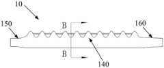
图3为本申请实施例所提供的波浪翼型叶片的结构示意图;3 is a schematic structural diagram of a wave airfoil blade provided by an embodiment of the application;
图4为图3的B-B剖视图;Fig. 4 is the B-B sectional view of Fig. 3;
图5为本申请实施例所提供的波浪翼型叶片的剖切图;5 is a cross-sectional view of a wave airfoil blade provided by an embodiment of the application;
图6为本申请实施例所提供的波浪翼型叶片与现有的波浪翼型叶片的数据对比图;6 is a data comparison diagram of a wave airfoil blade provided by an embodiment of the application and an existing wave airfoil blade;
图7为现有的波浪翼型叶片的波谷处流线图;Fig. 7 is the streamline diagram at the trough of the existing wave airfoil blade;
图8为本申请实施例所提供的波浪翼型叶片的波谷处流线图。FIG. 8 is a streamline diagram of a wave trough of a wave airfoil blade provided by an embodiment of the present application.
附图标记:Reference number:
1-风力机;1 - wind turbine;
10-波浪翼型叶片(简称叶片);10-Wave airfoil blade (blade for short);
110-波峰;110 - crest;
111-波峰顶端;111 - top of the crest;
120-波谷;120 - trough;
130-柱体;130 - cylinder;
140-中部;140 - middle;
150-根部;150 - root;
160-尖部;160 - tip;
170-缝隙;170 - gap;
180-叶片前缘;180 - the leading edge of the blade;
190-叶片后缘;190 - trailing edge of blade;
20-机舱;20 - cabin;
30-塔架;30 - tower;
40-整流罩。40 - Fairing.
此处的附图被并入说明书中并构成本说明书的一部分,示出了符合本申请的实施例,并与说明书一起用于解释本申请的原理。The accompanying drawings, which are incorporated in and constitute a part of this specification, illustrate embodiments consistent with the application and together with the description serve to explain the principles of the application.
具体实施方式Detailed ways
下面通过具体的实施例并结合附图对本申请做进一步的详细描述。The present application will be further described in detail below through specific embodiments and in conjunction with the accompanying drawings.
如图1-4所示,本申请实施例提供了一种波浪翼型叶片10,该波浪翼型叶片10作为用于风力发电的风力机的叶片使用,该波浪翼型叶片10包括在叶片前缘180沿该叶片10伸展方向连续分布的多个波峰110和多个波谷120,本申请中提到的多个为至少两个及两个以上特定数量个,相邻的两个波峰110之间连接有一柱体130,相邻的两个波峰110的排列方向和与前述二者相连的柱体130的轴向方向相同,且该柱体130的横截面积远小于与之相连的波峰110与之相对一面的截面积,也可以说,该柱体130的体积远小于叶片10的波峰110的体积,该柱体130只占该叶片10的较小部分,该柱体130的重量也相对较轻,整个叶片10的重量也不会有明显的增加,那么叶片10的输出功率也就不会有明显的降低,该叶片10的气动性能就不会有明显的下降。在保证叶片10的刚性满足其功能要求的前提下,可以采用重量较轻的材料制造该叶片10,例如铝合金、金属或非金属复合材料等,以进一步减轻其重量,使叶片10的输出功率的降低幅度更小。As shown in FIGS. 1 to 4 , an embodiment of the present application provides a
与现有技术相比,在相邻的两个波峰110之间连接一横截面积较小的柱体130,且相邻的波峰110的排列方向与柱体130的轴向相同,也就是说,在两个波峰110之间横向设置一个横截面积较小的柱体130,这样的结构设置使叶片10的结构更佳稳定、坚固、刚性更强,可以稳定控制住波峰110由于强烈来流而产生的震颤;而且由于柱体130的阻挡,还能够在一定程度上阻碍来流中夹杂的沙粒等物质对叶片10波谷120部位的磨损;另外,由于柱体130的横截面积较小,其重量也相对较轻,这样该叶片10的重量就不会有明显的增加,输出功率也不会有明显的降低,该叶片10的气动性能也不会有明显的下降,反而,该柱体130可以起到干扰波谷120处自然来流与波峰110处来流的作用,使两个来流在波谷120处前方不会产生干扰涡,从而使得波谷120处的流动分离推迟,进而使得整个波浪翼型叶片10发生失速的攻角增大,从而大大提升叶片10的气动性能。Compared with the prior art, a
具体的,如图7和图8所示,图7为现有的波浪翼型叶片的波谷处流线图,图8为本申请实施例所提供的波浪翼型叶片的波谷处流线图,图中深浅不同的线条代表各处不同的速度流动,颜色越深代表速度越快,如图7可知,现有的波浪翼型叶片的尾缘已经进入了深度失速,吸力面中部位置已经开始发生流动分离,叶片的表面的扰动涡十分巨大,这样会严重导致叶片气动性能急速降低。如图8可知,本申请提供的波浪翼型叶片10由于柱体130的存在,使波谷120位置处于背风面,当自然来流绕过柱体130后,增加了其本身的动量,从而产生一定的压差;又由于波峰110处下压力面的压力较大,使得气流从波峰110下压力面向上流动,产生附着涡;波峰110处的来流与柱体130的来流会在柱体130和波谷120的前缘之间的缝隙170处(如图1所示)发生混合,然后一起向波谷120的尾缘流动,但由于前述的缝隙170的大小较小,使得混合来流无法产生较大的扰动涡,从而抑制了较早的流动分离。因此,柱体130的存在能扰动自然来流和来自波峰两侧的气流,使得波谷120位置上吸力面的湍动量降低,气流扰动降低,进而延缓了该叶片10表面的失速。现有的波浪翼型叶片的波谷位置处发生流动分离较早,叶片表面的扰动较大,湍动量较大。然而,本申请实施例所提供的波浪翼型叶片10能使气流扰动降低,延缓叶片10表面失速,相较于现有的波浪翼型叶片来说,明显的提升了波浪翼型叶片10的气动性能。Specifically, as shown in FIGS. 7 and 8 , FIG. 7 is a streamline diagram at the trough of the existing wave airfoil blade, and FIG. 8 is a streamline diagram at the trough of the wave airfoil blade provided by the embodiment of the application, The lines with different shades in the figure represent different speed flows in different places. The darker the color, the faster the speed. As shown in Figure 7, the trailing edge of the existing wave airfoil blade has entered a deep stall, and the middle of the suction surface has begun to occur. When the flow is separated, the disturbance vortex on the surface of the blade is very large, which will seriously lead to the rapid reduction of the aerodynamic performance of the blade. As can be seen from FIG. 8 , the
如图6所示,为本申请实施例所提供的波浪翼型叶片与现有的波浪翼型叶片的升力和阻力系数数据对比图,如图6可知,在攻角逐渐增大的过程中,本申请所提供的波浪翼型叶片10的升力系数均高于现有的波浪翼型叶片的升力系数,且在水平轴风力机最佳攻角范围内(8度~18度)升力系数提升近10%,本申请实施例所提供的波浪翼型叶片10还使得失速攻角向后推迟了1~3度。从图中的阻力系数数据可以看出,在攻角度数为10度之前,本申请实施例所提供的波浪翼型叶片10的阻力系数较现有的波浪翼型叶片的阻力系数高,这是由于柱体130的存在而增加了叶片10表面的摩擦阻力,从而可以阻碍来流中夹杂的沙粒等物质对叶片10的磨损,进而延长叶片10的使用寿命,及降低后期维修成本;从攻角度数为10度之后,本申请实施例所提供的波浪翼型叶片10的阻力系数随着攻角的增加,其增加的趋势逐渐平缓,并低于现有的波浪翼型叶片的阻力系数,这是由于此时本申请实施例所提供的波浪翼型叶片10的压差阻力要低于现有的波浪翼型叶片的压差阻力,从而使在波谷120前缘不会产生干扰涡,进而提高叶片10的气动性能。As shown in FIG. 6 , a comparison chart of the lift and drag coefficient data between the wave airfoil blade provided in the embodiment of the application and the existing wave airfoil blade, as shown in FIG. 6 , in the process of gradually increasing the angle of attack, The lift coefficients of the
一种可选的实施例为,柱体130可以为一根较长的柱体130,该一根较长的柱体130可以直接贯穿整个叶片10,这样制作工艺简单。另一种优选的实施例为,该叶片10可以具有多根较短的柱体130,每个波谷120处均可以设置一根该柱体130,也可以部分波谷120处设置柱体130,部分波谷120处不设置柱体130,当然每个波谷120处均设置一根柱体130,也就是多个柱体130与多个波谷120一一对应设置的这种做法,相比于部分波谷120处设置柱体130,部分波谷120处不设置柱体130的这种做法来说,叶片10的结构更稳定,刚性更强,可以更牢固的控制住波峰110的震颤,叶片10阻挡来流夹杂的沙粒的能力也就更强,叶片10的磨损程度也就更小,干扰波谷120处自然来流与波峰110处来流的能力更强,更能进一步提升叶片10的气动性能。该优选的实施例相比于前述一根柱体130直接贯穿整个叶片10的这种可选的实施例来说,一方面减少了柱体130材料的使用量,减轻了柱体130的重量,进一步减轻了叶片10的重量,也就使叶片10的输出功率的降低幅度更小;另一方面,由于从一根较长的柱体130改成多个较短的柱体130,其强度、坚韧度也有所提高。In an optional embodiment, the
具体实施中,每个柱体130的两端可以直接搭接于与之相邻的两个波峰110,这种搭接的方式具体可以为焊接、粘接、卡接、铆接等,优选的可以采用平滑焊接,这样可以提高叶片表面的光滑度,减小对来流走向的影响,提高叶片10的气动性能。另外,为了提高柱体130的圆滑程度,以尽量减小对来流走势的影响,本申请实施例的柱体130具体可以为圆柱体。In a specific implementation, the two ends of each
另外,如图3所示,为了有效利用波浪翼型叶片10的波浪结构部位,在提高叶片10气动性能的同时,降低成本,提高风力发电的价格竞争力,波浪翼型叶片10的波浪结构部位(即具有波峰110和波谷120的部位)可以只设置在叶片10的中部140位置,而根部150和尖部160不进行设置。进一步的,为了使波浪结构部位得到较均匀的压差阻力,提高叶片10的稳定性,那么每相邻两个波峰顶端111之间的距离可以相等,每相邻两个波峰顶端111和波谷120底端的距离可以相等。In addition, as shown in FIG. 3 , in order to effectively utilize the wave structure part of the
如图5所示,图中标注出叶片10的各个特征,C为弦长(即波谷120底端到叶片后缘190边沿之间的距离),λ为波长(即相邻两个波峰110顶端之间的距离),A为振幅(即波峰顶端111与波谷120低端之间的距离),d为柱体130(圆柱体)的直径,L为柱体130面向波谷120的一侧到波谷120底端的距离。发明人根据实验累积经验以及现有的波浪翼型叶片的部分尺寸参数来得到本申请实验的波浪翼型叶片10的不变量(波长λ、振幅A等)的参数值,即波长λ的范围为[0.25C,0.5C],振幅A的范围为[0.025C,0.12C],从而通过实验及理论推出较优的柱体130的直径d以及柱体130面向波谷120的一侧到波谷120底端的距离L的尺寸数据,具体的,由动量-叶素理论可知,叶片升阻比大小直接影响风力机的发电效率,设定叶片运行工况相应的雷诺数Re,马赫数Ma以及攻角α,设定本申请的波浪翼型叶片10的升阻比Cld2与同种工况下现有的波浪翼型叶片的升阻比Cld1作比较,利用MATLAB中的求解最大值函数f(x)=max(Cld1/Cld2)进行求解,最终经计算获得直径d的范围为[0.02C,0.1C],L的范围为[0.1C,0.3C],也就是所述柱体130的直径大于等于0.02倍的弦长,且小于等于0.1倍的弦长,柱体130面向波谷120的一侧到波谷120底端的距离范围为大于等于0.1倍的弦长,且小于等于0.3倍的弦长。采用前述直径d及距离L的取值范围可以得到较优的本申请的波浪翼型叶片10,得到较小且合理尺寸的柱体130,使其本身的增加不会明显增加叶片10的重量,以及较小且合理的柱体130和波谷120的前缘之间的缝隙170,使得混合来流无法产生较大的扰动涡,从而抑制较早的流动分离,进而提高叶片10的气动性能。As shown in FIG. 5 , various features of the
更优选的,发明人在模拟验证分析时选用了气动性能优于现有的波浪翼型叶片的波浪翼型叶片的尺寸参数,即λ=0.25C,A=0.12C,对应的得出直径d与距离L的优化尺寸,即d=0.04C,L=0.2C。根据前述尺寸制造出的波浪翼型叶片10能够达到更大程度的性能优化,大大提高叶片10的输出功率,提高叶片10的气动性能。More preferably, the inventor selects the size parameters of the wave airfoil blade whose aerodynamic performance is better than the existing wave airfoil blade in the simulation verification analysis, that is, λ=0.25C, A=0.12C, and the corresponding diameter d is obtained. Optimal dimensions with distance L, ie d=0.04C, L=0.2C. The
另外,为了提高柱体130的耐磨性,以提高柱体130的使用寿命,进而提高叶片10的使用寿命,以及降低叶片10后期的维修成本,在保证叶片10的刚性满足其功能要求的前提下,柱体130可以采用耐磨的材料制成,例如高锰钢(ZGMn13)、高锰合金(ZGMn13Cr2MoRe)、超高锰合金(ZGMn18Cr2MoRe)、高、中、低铬合金铸铁(如Cr15MOZCu)和中、低、高碳多元金合钢(如ZG40SiMnCrMO和ZG35Cr2MoNiRe)、奥贝球铁(ADI)以及各类复合或梯度材料及硬质合金材料等,由于柱体130的体积较小,采用了前述这类耐磨材料也不会明显的增加叶片10的重量,不会明显降低其输出功率,但是却减少了叶片后期维护的费用,降低了风力发电成本,进而提高了风力发电的价格竞争力。In addition, in order to improve the wear resistance of the
如图1所示,本申请实施例还提供了一种风力机1,该风力机1包括前述实施例中的任一种波浪翼型叶片10,以及机舱20、塔架30和整流罩40,该风力机1包括至少三个叶片10,各叶片10的根部150均固定连接于整流罩40外周,且各叶片10沿整流罩40外周均匀分布,该整流罩40与机舱20固定连接,该机舱20架设在塔架30上。本申请实施例提高了波浪翼型叶片10的输出功率,进而提高了该风力机1的发电功率,同时降低了该风力机1的成本,提高了该风力机1的价格竞争力,进而可以使该风力机1可以得到更广泛的采用。As shown in FIG. 1 , an embodiment of the present application further provides a wind turbine 1 , the wind turbine 1 includes any one of the
以上所述仅为本申请的较佳实施例而已,并不用以限制本申请,对于本领域的技术人员来说,本申请可以有各种更改和变化。凡在本申请的精神和原则之内,所作的任何修改、等同替换、改进等,均应包含在本申请的保护范围之内。The above descriptions are only preferred embodiments of the present application, and are not intended to limit the present application. For those skilled in the art, the present application may have various modifications and changes. Any modification, equivalent replacement, improvement, etc. made within the spirit and principle of this application shall be included within the protection scope of this application.
Claims (10)
Priority Applications (1)
| Application Number | Priority Date | Filing Date | Title |
|---|---|---|---|
| CN201810872370.2ACN109083806B (en) | 2018-08-02 | 2018-08-02 | Wave wing type blade and wind turbine |
Applications Claiming Priority (1)
| Application Number | Priority Date | Filing Date | Title |
|---|---|---|---|
| CN201810872370.2ACN109083806B (en) | 2018-08-02 | 2018-08-02 | Wave wing type blade and wind turbine |
Publications (2)
| Publication Number | Publication Date |
|---|---|
| CN109083806A CN109083806A (en) | 2018-12-25 |
| CN109083806Btrue CN109083806B (en) | 2020-03-13 |
Family
ID=64833681
Family Applications (1)
| Application Number | Title | Priority Date | Filing Date |
|---|---|---|---|
| CN201810872370.2AExpired - Fee RelatedCN109083806B (en) | 2018-08-02 | 2018-08-02 | Wave wing type blade and wind turbine |
Country Status (1)
| Country | Link |
|---|---|
| CN (1) | CN109083806B (en) |
Families Citing this family (4)
| Publication number | Priority date | Publication date | Assignee | Title |
|---|---|---|---|---|
| AT522086B1 (en)* | 2019-03-19 | 2020-08-15 | Schmidt Michael | AERODYNAMIC COMPONENT |
| CN113482843B (en)* | 2021-08-05 | 2022-08-05 | 大连理工大学 | A bionic airfoil vertical axis hydro turbine power generation device |
| CN118728649B (en)* | 2024-08-26 | 2024-12-17 | 广州蓝色能源研究院 | Vertical axis lift type wind driven generator and self-powered wind speed warning system |
| CN119840755B (en)* | 2025-03-20 | 2025-07-22 | 浙江远算科技有限公司 | Cycling taillight |
Family Cites Families (10)
| Publication number | Priority date | Publication date | Assignee | Title |
|---|---|---|---|---|
| US4886421A (en)* | 1984-01-09 | 1989-12-12 | Wind Feather, United Science Asc. | Wind turbine air foil |
| EP1338793A3 (en)* | 2002-02-22 | 2010-09-01 | Mitsubishi Heavy Industries, Ltd. | Serrated wind turbine blade trailing edge |
| CN201428551Y (en)* | 2009-07-22 | 2010-03-24 | 中国科学院工程热物理研究所 | Wind turbine blade with concave-convex leading edge structure |
| CN201461226U (en)* | 2009-08-05 | 2010-05-12 | 中国科学院工程热物理研究所 | a leaf |
| US9249666B2 (en)* | 2011-12-22 | 2016-02-02 | General Electric Company | Airfoils for wake desensitization and method for fabricating same |
| ES2864028T3 (en)* | 2015-05-21 | 2021-10-13 | Siemens Gamesa Renewable Energy As | Toothed rotor blade for wind turbine |
| EP3112667B1 (en)* | 2015-06-30 | 2020-08-26 | Vestas Wind Systems A/S | Anti-oscillation tool |
| US10240576B2 (en)* | 2015-11-25 | 2019-03-26 | General Electric Company | Wind turbine noise reduction with acoustically absorbent serrations |
| JP2017120072A (en)* | 2015-12-28 | 2017-07-06 | 明久 松園 | Corrugated lift enhancement blade |
| CN206707918U (en)* | 2017-02-10 | 2017-12-05 | 中国电力工程顾问集团华北电力设计院有限公司 | Waveform trailing edge blade and H type vertical-shaft aerogenerators |
- 2018
- 2018-08-02CNCN201810872370.2Apatent/CN109083806B/ennot_activeExpired - Fee Related
Also Published As
| Publication number | Publication date |
|---|---|
| CN109083806A (en) | 2018-12-25 |
Similar Documents
| Publication | Publication Date | Title |
|---|---|---|
| CN109083806B (en) | Wave wing type blade and wind turbine | |
| EP2604856B1 (en) | Wind turbine blade, wind power generation device provided with same, and design method for wind turbine blade | |
| US8573541B2 (en) | Wavy airfoil | |
| US9677537B2 (en) | Acoustic shield for noise reduction in wind turbines | |
| US9951749B2 (en) | System and method for trailing edge noise reduction of a wind turbine blade | |
| CN105715449B (en) | Rotor blades and wind turbines with vortex generators | |
| CN101596934B (en) | Wingtip eddy diffusion device | |
| CN202023688U (en) | Wind turbine blade with blunt trailing edge | |
| EP2031244A1 (en) | Means to maintain flow of a flowing medium attached to the exterior of a flow control member by use of crossing sub-channels | |
| KR20130112772A (en) | Slat with tip vortex modification appendage for wind turbine | |
| CN101649807A (en) | Wind turbine blade planforms with twisted and tapered tips | |
| WO2009026928A2 (en) | Wind turbine blade with submerged boundary layer control means | |
| JP6783211B2 (en) | How to determine the placement of the vortex generator on the wind turbine blades and wind turbine blades | |
| CN104364517A (en) | Twisted blade root | |
| EP3181895A1 (en) | Splitter plate arrangement for a serrated wind turbine blade | |
| WO2011106733A2 (en) | Advanced aerodynamic and structural blade and wing design | |
| CN106949021A (en) | It is a kind of that the pneumatic equipment bladess of stalling characteristics are improved based on Fractal optimization | |
| KR102197679B1 (en) | Blade of vertical axis wind turbine with longitudinal strips to increase aerodynamic performanc | |
| KR102144276B1 (en) | Ship with small duct and method for assessing application of small duct on ship | |
| JP2015078667A (en) | Wind turbine blade and wind power generator | |
| CN205633013U (en) | Rotatory wind wheel circular rector control type wing | |
| US11028823B2 (en) | Wind turbine blade with tip end serrations | |
| CN207554255U (en) | A kind of band winglet and the up-front darrieus marine tidal-current energy runner bucket of shaped form | |
| CN113513368B (en) | Turbine capable of directly backing with primary and secondary moving blade structures | |
| EP2851556A1 (en) | Arrangement to reduce noise of a wind turbine rotor blade |
Legal Events
| Date | Code | Title | Description |
|---|---|---|---|
| PB01 | Publication | ||
| PB01 | Publication | ||
| SE01 | Entry into force of request for substantive examination | ||
| SE01 | Entry into force of request for substantive examination | ||
| GR01 | Patent grant | ||
| CF01 | Termination of patent right due to non-payment of annual fee | ||
| CF01 | Termination of patent right due to non-payment of annual fee | Granted publication date:20200313 Termination date:20210802 |