CN109075458B - Apparatus and method for beamforming tracking - Google Patents
Apparatus and method for beamforming trackingDownload PDFInfo
- Publication number
- CN109075458B CN109075458BCN201680083078.1ACN201680083078ACN109075458BCN 109075458 BCN109075458 BCN 109075458BCN 201680083078 ACN201680083078 ACN 201680083078ACN 109075458 BCN109075458 BCN 109075458B
- Authority
- CN
- China
- Prior art keywords
- phase shift
- phase
- signal
- antenna
- variable
- Prior art date
- Legal status (The legal status is an assumption and is not a legal conclusion. Google has not performed a legal analysis and makes no representation as to the accuracy of the status listed.)
- Active
Links
Images


Classifications
- H—ELECTRICITY
- H01—ELECTRIC ELEMENTS
- H01Q—ANTENNAS, i.e. RADIO AERIALS
- H01Q3/00—Arrangements for changing or varying the orientation or the shape of the directional pattern of the waves radiated from an antenna or antenna system
- H01Q3/26—Arrangements for changing or varying the orientation or the shape of the directional pattern of the waves radiated from an antenna or antenna system varying the relative phase or relative amplitude of energisation between two or more active radiating elements; varying the distribution of energy across a radiating aperture
- H01Q3/30—Arrangements for changing or varying the orientation or the shape of the directional pattern of the waves radiated from an antenna or antenna system varying the relative phase or relative amplitude of energisation between two or more active radiating elements; varying the distribution of energy across a radiating aperture varying the relative phase between the radiating elements of an array
- H01Q3/34—Arrangements for changing or varying the orientation or the shape of the directional pattern of the waves radiated from an antenna or antenna system varying the relative phase or relative amplitude of energisation between two or more active radiating elements; varying the distribution of energy across a radiating aperture varying the relative phase between the radiating elements of an array by electrical means
- H01Q3/36—Arrangements for changing or varying the orientation or the shape of the directional pattern of the waves radiated from an antenna or antenna system varying the relative phase or relative amplitude of energisation between two or more active radiating elements; varying the distribution of energy across a radiating aperture varying the relative phase between the radiating elements of an array by electrical means with variable phase-shifters
- H01Q3/38—Arrangements for changing or varying the orientation or the shape of the directional pattern of the waves radiated from an antenna or antenna system varying the relative phase or relative amplitude of energisation between two or more active radiating elements; varying the distribution of energy across a radiating aperture varying the relative phase between the radiating elements of an array by electrical means with variable phase-shifters the phase-shifters being digital
- G—PHYSICS
- G01—MEASURING; TESTING
- G01S—RADIO DIRECTION-FINDING; RADIO NAVIGATION; DETERMINING DISTANCE OR VELOCITY BY USE OF RADIO WAVES; LOCATING OR PRESENCE-DETECTING BY USE OF THE REFLECTION OR RERADIATION OF RADIO WAVES; ANALOGOUS ARRANGEMENTS USING OTHER WAVES
- G01S3/00—Direction-finders for determining the direction from which infrasonic, sonic, ultrasonic, or electromagnetic waves, or particle emission, not having a directional significance, are being received
- G01S3/02—Direction-finders for determining the direction from which infrasonic, sonic, ultrasonic, or electromagnetic waves, or particle emission, not having a directional significance, are being received using radio waves
- G01S3/14—Systems for determining direction or deviation from predetermined direction
- G01S3/38—Systems for determining direction or deviation from predetermined direction using adjustment of real or effective orientation of directivity characteristic of an antenna or an antenna system to give a desired condition of signal derived from that antenna or antenna system, e.g. to give a maximum or minimum signal
- G—PHYSICS
- G01—MEASURING; TESTING
- G01S—RADIO DIRECTION-FINDING; RADIO NAVIGATION; DETERMINING DISTANCE OR VELOCITY BY USE OF RADIO WAVES; LOCATING OR PRESENCE-DETECTING BY USE OF THE REFLECTION OR RERADIATION OF RADIO WAVES; ANALOGOUS ARRANGEMENTS USING OTHER WAVES
- G01S3/00—Direction-finders for determining the direction from which infrasonic, sonic, ultrasonic, or electromagnetic waves, or particle emission, not having a directional significance, are being received
- G01S3/02—Direction-finders for determining the direction from which infrasonic, sonic, ultrasonic, or electromagnetic waves, or particle emission, not having a directional significance, are being received using radio waves
- G01S3/14—Systems for determining direction or deviation from predetermined direction
- G01S3/46—Systems for determining direction or deviation from predetermined direction using antennas spaced apart and measuring phase or time difference between signals therefrom, i.e. path-difference systems
- H—ELECTRICITY
- H01—ELECTRIC ELEMENTS
- H01Q—ANTENNAS, i.e. RADIO AERIALS
- H01Q25/00—Antennas or antenna systems providing at least two radiating patterns
- H01Q25/004—Antennas or antenna systems providing at least two radiating patterns providing two or four symmetrical beams for Janus application
- H—ELECTRICITY
- H01—ELECTRIC ELEMENTS
- H01Q—ANTENNAS, i.e. RADIO AERIALS
- H01Q25/00—Antennas or antenna systems providing at least two radiating patterns
- H01Q25/02—Antennas or antenna systems providing at least two radiating patterns providing sum and difference patterns
- H—ELECTRICITY
- H01—ELECTRIC ELEMENTS
- H01Q—ANTENNAS, i.e. RADIO AERIALS
- H01Q21/00—Antenna arrays or systems
- H01Q21/06—Arrays of individually energised antenna units similarly polarised and spaced apart
- H—ELECTRICITY
- H01—ELECTRIC ELEMENTS
- H01Q—ANTENNAS, i.e. RADIO AERIALS
- H01Q21/00—Antenna arrays or systems
- H01Q21/06—Arrays of individually energised antenna units similarly polarised and spaced apart
- H01Q21/08—Arrays of individually energised antenna units similarly polarised and spaced apart the units being spaced along or adjacent to a rectilinear path
Landscapes
- Physics & Mathematics (AREA)
- Engineering & Computer Science (AREA)
- General Physics & Mathematics (AREA)
- Radar, Positioning & Navigation (AREA)
- Remote Sensing (AREA)
- Variable-Direction Aerials And Aerial Arrays (AREA)
Abstract
Description
Translated fromChinese相关申请的交叉引用CROSS-REFERENCE TO RELATED APPLICATIONS
本申请要求于2016年6月16日提交的美国专利申请第15/184,006号的优先权,并且该申请通过引用并入本文。This application claims priority to US Patent Application No. 15/184,006, filed June 16, 2016, and incorporated herein by reference.
技术领域technical field
本公开内容总体涉及通信,并且具体地涉及用于天线阵列的波束成形跟踪。The present disclosure relates generally to communications, and in particular to beamforming tracking for antenna arrays.
背景技术Background technique
具有多个天线元件的天线阵列被用于各种类型的通信设备中。对被馈送到天线阵列的天线元件和从天线阵列的天线元件馈送的信号的相位的控制使得能够操纵天线波束。这被称为波束操纵或波束成形。Antenna arrays with multiple antenna elements are used in various types of communication devices. Control of the phases of the signals fed to and from the antenna elements of the antenna array enables the antenna beam to be steered. This is called beam steering or beamforming.
发明内容SUMMARY OF THE INVENTION
可变相移器被耦接用以从天线阵列中的相应天线元件接收信号。每个可变相移器包括一对相移元件,该对相移元件施加与可变相移器从其接收信号的天线元件所关联的通道相移有关的相应的相移。这些相应的相移对应于与天线阵列的当前天线波束方向的侧角。波束成形跟踪控制器被耦接用以从可变相移器接收相移信号,并且被配置成基于相移信号生成控制信号以控制通道相移。波束成形跟踪控制器可以在模拟电路系统中实现,或者实现为数字组件例如处理器或者被配置成生成控制信号的其他电子装置。Variable phase shifters are coupled to receive signals from corresponding antenna elements in the antenna array. Each variable phase shifter includes a pair of phase shifting elements that apply a respective phase shift related to the phase shift of the channel associated with the antenna element from which the variable phase shifter receives signals. These corresponding phase shifts correspond to side angles from the current antenna beam direction of the antenna array. A beamforming tracking controller is coupled to receive the phase shift signal from the variable phase shifter, and is configured to generate a control signal based on the phase shift signal to control the channel phase shift. The beamforming tracking controller may be implemented in analog circuitry, or as a digital component such as a processor or other electronic device configured to generate control signals.
在另一实施方式中,一种方法涉及:从天线阵列中的天线元件接收信号,施加与天线元件所关联的通道相移有关的相应的相移,并且基于相移信号生成控制信号以控制通道相移。In another embodiment, a method involves receiving a signal from an antenna element in an antenna array, applying a corresponding phase shift related to the phase shift of a channel associated with the antenna element, and generating a control signal to control the channel based on the phase shift signal phase shift.
通过向由天线元件接收的信号施加通道相移并且然后向通道相移信号施加相应的有关相移,可以分别施加通道相移和与通道相移有关的相应的相移。在另一实施方式中,通过施加以下第一相移和第二相移来对由每个天线元件接收的信号进行相移,第一相移与和天线元件相关联的通道相移加上与第一方向上的第一侧角对应的δ相移对应,第二相移与通道相移减去与不同于第一方向的第二方向上的第二侧角对应的δ相移对应。By applying a channel phase shift to the signal received by the antenna element and then applying a corresponding relative phase shift to the channel phase shifted signal, the channel phase shift and the corresponding phase shift related to the channel phase shift can be applied, respectively. In another embodiment, the signal received by each antenna element is phase shifted by applying a first phase shift and a second phase shift, the first phase shift being the channel phase shift associated with the antenna element plus the The delta phase shift corresponding to the first side angle in the first direction corresponds to the delta phase shift corresponding to the channel phase shift minus the delta phase shift corresponding to the second side angle in the second direction different from the first direction.
波束成形跟踪可以结合一维线性天线阵列和在相反的方向上的与天线阵列的当前天线波束方向的侧角来实现。在二维阵列中,侧角在四个方向上,并且与通道相移有关并且与四个侧角对应的相应的相移被施加至所接收的信号。Beamforming tracking can be implemented in combination with a one-dimensional linear antenna array and a flank angle in the opposite direction to the current antenna beam direction of the antenna array. In a two-dimensional array, the side angles are in four directions, and the channel phase shifts are related and corresponding phase shifts corresponding to the four side angles are applied to the received signal.
在一些实施方式中,通过相应的相移进行相移的信号被组合,以实现例如余弦窗函数。In some embodiments, the signals phase-shifted by respective phase shifts are combined to implement, for example, a cosine window function.
信号放大、下变频和模数转换中的任何一个或更多个也可以在接收信号路径中实现。Any one or more of signal amplification, down-conversion, and analog-to-digital conversion may also be implemented in the receive signal path.
通信设备可以包括天线阵列、可变相移器和波束成形跟踪控制器,以在用户设备和/或通信网络设备中实现波束成形跟踪。这种通信设备还可以包括接收器、发送器或收发器。The communication device may include an antenna array, a variable phase shifter and a beamforming tracking controller to enable beamforming tracking in user equipment and/or communication network equipment. Such communication devices may also include receivers, transmitters or transceivers.
类似地,该方法可以在用户设备和/或通信网络设备中实现。Similarly, the method may be implemented in user equipment and/or communication network equipment.
还设想了其他实施方式。例如,非暂态处理器可读介质可以用于存储指令,所述指令在由一个或更多个处理器执行时使一个或更多个处理器执行一种方法。这种方法可以涉及:接收相移信号,该相移信号在天线元件处被接收并且通过与通道相移有关的相应的相移来进行相移;以及基于相移信号生成控制信号以控制通道相移。Other implementations are also contemplated. For example, a non-transitory processor-readable medium may be used to store instructions that, when executed by one or more processors, cause one or more processors to perform a method. Such a method may involve: receiving a phase-shifted signal, the phase-shifted signal being received at the antenna element and being phase-shifted by a corresponding phase-shift related to the channel phase-shift; and generating a control signal based on the phase-shifted signal to control the channel phase shift.
对于本领域普通技术人员而言,在阅读以下描述时,本公开内容的实施方式的其他方面和特征将变得明显。Other aspects and features of embodiments of the present disclosure will become apparent to those of ordinary skill in the art upon reading the following description.
附图说明Description of drawings
现在将参照附图更详细地描述本发明的实施方式的示例。Examples of embodiments of the present invention will now be described in more detail with reference to the accompanying drawings.
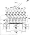
图1是根据实施方式的具有主通道路径、侧通道路径、可变主通道相移元件和固定侧通道相移元件的示例波束成形跟踪设备的框图。1 is a block diagram of an example beamforming tracking device having a main channel path, a side channel path, a variable main channel phase shift element, and a fixed side channel phase shift element, according to an embodiment.
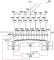
图2是根据另一实施方式的具有侧通道路径、可变侧通道相移元件和信号组合器的示例波束成形跟踪设备的框图。2 is a block diagram of an example beamforming tracking device with side channel paths, variable side channel phase shift elements, and signal combiners, according to another embodiment.
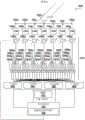
图3是根据另一实施方式的具有侧通道路径、可变主通道相移元件、固定侧通道相移元件和信号组合器的示例波束成形跟踪设备的框图。3 is a block diagram of an example beamforming tracking device with side channel paths, variable main channel phase shift elements, fixed side channel phase shift elements, and signal combiners, according to another embodiment.
图4是根据另一实施方式的具有模拟跟踪控制器的示例波束成形跟踪设备的框图。4 is a block diagram of an example beamforming tracking device with an analog tracking controller, according to another embodiment.
图5是根据另一实施方式的用于利用数字跟踪控制器进行二维波束成形跟踪的示例波束成形跟踪设备的框图。5 is a block diagram of an example beamforming tracking apparatus for two-dimensional beamforming tracking with a digital tracking controller, according to another embodiment.
图5A示出了二维波束成形跟踪的示例。Figure 5A shows an example of two-dimensional beamforming tracking.
图6是根据另一实施方式的用于利用模拟跟踪控制器进行二维波束成形跟踪的示例波束成形跟踪设备的框图。6 is a block diagram of an example beamforming tracking apparatus for two-dimensional beamforming tracking using an analog tracking controller, according to another embodiment.
图7是示例通信设备的框图。7 is a block diagram of an example communication device.
图8是示例通信系统的框图。8 is a block diagram of an example communication system.
图9是示出示例波束成形跟踪方法的流程图。9 is a flowchart illustrating an example beamforming tracking method.
图10是模拟结果的曲线图,并且示出了用于到达角(angle of arrival,AoA)梯度方法和幂律(power law)方法的频谱函数。10 is a graph of the simulation results and shows the spectral functions for the angle of arrival (AoA) gradient method and the power law method.
图11是模拟结果的另一曲线图,并且示出了在天线波束与所接收信号的到达方向对准时的用于AoA梯度方法和幂律方法的频谱函数。Figure 11 is another graph of the simulation results and shows the spectral functions for the AoA gradient method and the power law method when the antenna beam is aligned with the direction of arrival of the received signal.
图12是模拟结果的又一曲线图,示出了针对基于组合两个侧信号的天线方向图和基于主通道路径而没有信号组合的天线方向图的信号功率与方位角的关系。12 is yet another graph of simulation results showing signal power versus azimuth for an antenna pattern based on combining the two side signals and an antenna pattern based on the main channel path without signal combining.
具体实施方式Detailed ways
根据一种传统的波束成形跟踪技术,阵列中的每个天线元件连接至相应的数字处理通道。所接收信号的目标跟踪通常是基于诸如多信号分类(Multiple SignalClassification,MUSIC)算法或借助于旋转不变技术的信号参数估计(Estimation ofSignal Parameters via Rotational Invariance Technique,ESPRIT)算法的算法。这种跟踪技术的优点是具有高跟踪精度。然而,还存在缺点,即在硬件中实现非常昂贵。每个天线元件需要单独的数字处理通道,这对于大量天线元件是不实用的。例如,天线阵列可以包括超过一百个天线元件,对于这些天线元件,单独的数字处理通道可能是不实用的。According to one conventional beamforming tracking technique, each antenna element in the array is connected to a corresponding digital processing channel. Target tracking of received signals is usually based on algorithms such as Multiple Signal Classification (MUSIC) algorithms or Estimation of Signal Parameters via Rotational Invariance Technique (ESPRIT) algorithms. The advantage of this tracking technique is high tracking accuracy. However, there is also the disadvantage that it is very expensive to implement in hardware. Each antenna element requires a separate digital processing channel, which is not practical for a large number of antenna elements. For example, an antenna array may include more than a hundred antenna elements for which a separate digital processing channel may not be practical.
另一传统技术涉及在与当前天线波束角有关的相反方向上扫描两个“δ”角或侧角。在两个时隙中扫描两个δ角,并且然后基于总接收信号具有更强功率的δ角来确定波束角应被移动的方向。这是一种简单、鲁棒的算法,但是由于与在各个时隙中分开地扫描δ角相关联的波束切换时间和基带处理时间而涉及高系统开销和慢响应(几毫秒或更长)。该技术在使用抖动方法的跟踪模式下也倾向于低信噪比(Signal to Noise Ratio,SNR),失去用于跟踪的几个dB的SNR。Another conventional technique involves scanning two "delta" or side angles in opposite directions relative to the current antenna beam angle. The two delta angles are scanned in two time slots, and then the direction in which the beam angle should be shifted is determined based on the delta angle with the greater power of the total received signal. This is a simple, robust algorithm, but involves high overhead and slow response (milliseconds or more) due to beam switching time and baseband processing time associated with scanning the delta angle separately in each slot. This technique also tends to have a low Signal to Noise Ratio (SNR) in the tracking mode using the dithering method, losing several dB of SNR for tracking.
本文公开的实施方式提供与中心通道信号处理同时进行的δ角信号处理,而不需要用于每个天线元件的单独的数字处理通道或用于捕获或处理每个δ角信号或“侧信号”的单独时隙。与和当前天线波束方向不同的方向上的δ角对应的δ角相移被施加至所接收的信号。然后,施加至在相应天线元件处接收的信号的通道相移被控制,以基于δ角相移信号自适应地重新对准波束方向。相对于为每个天线元件提供单独的数字处理通道,复杂性和硬件成本可以更低,并且波束跟踪可以比在涉及相应时隙中的δ角扫描的实现方式中更快。Embodiments disclosed herein provide simultaneous delta angle signal processing with center channel signal processing without requiring a separate digital processing channel for each antenna element or for capturing or processing each delta angle signal or "side signal" a separate time slot. A delta angle phase shift corresponding to the delta angle in a direction different from the current antenna beam direction is applied to the received signal. The channel phase shift applied to the signal received at the corresponding antenna element is then controlled to adaptively realign the beam direction based on the delta angle phase shifted signal. Relative to providing a separate digital processing channel for each antenna element, the complexity and hardware cost can be lower, and beam tracking can be faster than in implementations involving delta angle scanning in the corresponding time slot.
图1是根据实施方式的具有主通道路径、侧通道路径、可变主通道相移元件和固定侧通道相移元件的示例波束成形跟踪设备的框图。设备100包括:天线元件102a至102g,低噪声放大器(Low-Noise Amplifier,LNA)104a至104g,通常表示为112的可变相移器,下变频器114、116、118,模数转换器(analog to digital converter,ADC)120、122、124以及跟踪控制器126。在所示的示例中有七个可变相移器112,并且每个可变相移器包括一个可变相移元件106a至106g和一对固定相移元件108a/110a至108g/110g。跟踪控制器126与可变相移元件106a至106g之间的虚线表示用于从跟踪控制器向可变相移元件提供控制信号的控制连接。1 is a block diagram of an example beamforming tracking device having a main channel path, a side channel path, a variable main channel phase shift element, and a fixed side channel phase shift element, according to an embodiment.
天线元件102a至102g形成天线阵列。天线元件102a至102g可以采用各种形式中的任何一种,这取决于实现图1所示的组件的通信设备的类型。贴片天线元件可以在用户设备中实现,例如在空间有限的情况下,然而物理上更大的天线阵列孔径可以在网络设备中实现。The
LNA在无线通信设备中是常见的,并且各种放大器电路系统实现方式中的任何一个可以用于LNA 104a至104g。LNAs are common in wireless communication devices, and any of a variety of amplifier circuitry implementations may be used for LNAs 104a through 104g.
还存在用于实现可变相移元件106a至106g和固定相移元件108a至108g、110a至110g的各种选择。例如,矢量调制器可以用于实现可变相移元件106a至106g。固定延迟线表示用于实现固定相移元件108a至108g、110a至110g的一种可能的选择。使用与多个固定延迟线耦接的单极多掷开关实现固定相移元件108a至108g、110a至110g中的每一个可以提供由固定相移元件施加的δ角相移的选择性。因此,在每个实施方式中,固定相移元件108a至108g、110a至110g的δ角或“侧角”不需要被固定在仅一个特定值。可变相移元件106a至106g将具有比固定相移元件108a至108g、110a至110g更高的分辨率和更大的相移范围,但是在一些实施方式中,在由固定相移元件施加的δ角相移中可以存在一些灵活性或可调节性。使用多个固定延迟线实现固定相移元件108a至108g、110a至110g也可以为优选的或替代为优选的,以使得能够通过改变开关位置来为波束成形跟踪的不同应用设置不同的δ角,而不需要改变电路结构。There are also various options for implementing the variable
下变频器在无线通信设备中也很常见,用于将射频(radio frequency,RF)信号转换成中频(Intermediate Frequency,IF)信号或低频信号。这种频率转换通常涉及将信号混合。可以使用各种类型的频率转换电路系统中的任何一种来实现下变频器114、116、118。Downconverters are also common in wireless communication devices for converting radio frequency (RF) signals into intermediate frequency (IF) signals or low frequency signals. This frequency conversion usually involves mixing the signals. The
在一个实施方式中,以RF互补金属氧化物半导体(Complementary Metal OxideSemiconductor,CMOS)技术实现LNA 104a至104g、可变相移器112和下变频器114、116、118。与其他技术相比,这可以提供物理上小的解决方案,尤其是当实现多RF通道集成电路(integrated circuit,IC)时。更小和更多功能的IC设计也可以简化相控阵列天线设计。In one embodiment, the
ADC在无线通信设备中也是常见的,并且可以使用各种类型的ADC电路系统中的任何一种来实现ADC 120、ADC 122、ADC 124。ADCs are also common in wireless communication devices, and
跟踪控制器126可以使用硬件、固件或执行软件的一个或更多个组件或其某种组合来实现。可以适于实现跟踪控制器126的电子装置除此之外还包括微处理器、微控制器、可编程逻辑器件(Programmable Logic Device,PLD)、现场可编程门阵列(FieldProgrammable Gate Array,FPGA)、专用集成电路(Application Specific IntegratedCircuit,ASIC)和其他类型的“智能”集成电路。软件可以被存储在存储器中以供执行。存储器可以包括一个或更多个物理存储器装置,一个或更多个物理存储器装置包括各种类型的固态存储器装置和/或具有可移动或者甚至可移除的存储介质的存储器装置中的任何一个。
在天线元件102a至102g处接收的信号由LNA 104a至104g放大。可能不会在所有实施方式中将所接收的信号放大,并且因此LNA 104a至104g是可选的。在发送信号路径中,相移器通常位于放大器之前以进行线性化。Signals received at
可变相移元件106a至106g由跟踪控制器126控制,以将相应的相移施加至所接收的信号。可以认为每个天线元件102a至102g接收向其施加了相应的通道相移的相应的波束成形通道。这些通道相移控制波束方向或“操纵”天线元件102a至102g的阵列的天线波束。每个可变相移元件106a至106g被控制以施加与和每个可变相移元件从其接收信号的天线元件102a至102g相关联的通道相移对应的相应的相移。The variable
固定相移元件108a/110a至108g/110g实现了δ角方向性的形式。对于一维线性天线阵列,由固定相移元件108a至108g施加的相移对应于相反的方向或极性上的与当前天线波束方向的侧角。在图1所示的实施方式中,由固定相移元件108a至108g施加的相移是2*π*n*d*sin(δ)/λ,并且由固定相移元件110a至110g施加的相移是2*π*n*d*sin(-δ)/λ。在这些表达式中,n是固定相移元件108a至108g、110a至110g从其接收信号的天线元件的指示并且对于示例设备100从1到7变化,d是如图1至4中示出的线性阵列中的天线元件102a至102g之间的距离,δ是δ角,并且λ是接收的信号的波长。The fixed
下变频器114耦接至固定相移元件108a至108g,固定相移元件108a至108g施加与一个方向上的第一侧角对应的第一相移,并且下变频器118耦接至固定相移元件110a至110g,固定相移元件110a至110g施加与第二侧角对应的相移,第二侧角具有与第一侧角相同的大小但是在一维线性天线阵列的相反方向上,在该一维线性天线阵列中,波束成形跟踪灵敏度或分辨率在两个跟踪方向上将是相同的。设备100还具有将下变频器116耦接至可变相移元件106a至106g的主通道路径。在一些实施方式中,可以在不由下变频器114、116、118进行下变频的情况下执行对相移信号的进一步处理,并且因此下变频器是可选的。
ADC 120、ADC 122、ADC 124耦接至设备100中的下变频器114、116、118,并且将信号从模拟转换为数字。跟踪控制器126接收数字信号并且生成控制信号以控制由可变相移元件106a至106g施加的通道相移。
在实施方式中,跟踪控制器126实现基于所接收的信号的功率的跟踪,其在本文中也称为“幂律”跟踪。例如,将所接收的信号的到达角表示为
如果
则将光束方向向右移动跟踪角,Then move the beam direction to the right by the tracking angle,
否则,将光束方向向左移动跟踪角。Otherwise, move the beam direction to the left by the tracking angle.
在以上示例中,跟踪控制器126不需要耦接至主通道ADC 122,因为该幂律跟踪示例仅使用功率

幂律跟踪还可以涉及或者替代地涉及将功率


天线波束以其被重新对准的跟踪角不必与δ角相同。在一些实施方式中,跟踪角是固定的,但是在其他实施方式中可以替代地基于功率

在另一实施方式中,跟踪控制器126使用到达角(AoA)梯度跟踪。例如,可以根据MUSIC算法计算相关矩阵和2×2相关矩阵的2×2特征分解。然后可以通过采用MUSIC成本函数的导数来确定AoA梯度。In another embodiment, the tracking
控制信号被提供给可变相移器112,并且特别地被提供给设备100中的可变相移元件106a至106g。控制信号也可以被提供给固定相移元件108a至108g、110a至110g。如上所指出的,固定相移元件108a至108g、110a至110g可以使用多个固定延迟线来实现。这种实现可以提供不同的固定相移之间的选择。The control signal is provided to the
设备100包括波束成形跟踪中可以涉及的组件。实现设备100的通信设备或者设备100所耦接至的通信设备也可以包括其他组件。例如,从主通道接收的信号转换的数字信号可以被提供给接收器或收发器的基带处理电路系统。这通常在图1中由标签“到基带”表示。
图2是根据另一实施方式的具有侧通道路径、可变侧通道相移元件和数字信号组合器的示例波束成形跟踪设备的框图。设备200在结构和操作上与图1中的设备100类似。然而,设备200包括可变相移器212的不同实现方式。在设备200中,每个可变相移器仅包括一对固定相移元件208a/210a至208g/210g。设备200还包括仅“侧”通道下变频器114、118和ADC 120、ADC 124。在该实施方式中,没有主通道下变频器和主通道ADC。设备200替代地包括信号组合器228。如图1中,图2中的虚线表示控制连接。在图2中,控制连接用于从跟踪控制器226向可变相移元件208a至208g、210a至210g提供控制信号。2 is a block diagram of an example beamforming tracking device with side channel paths, variable side channel phase shifting elements, and a digital signal combiner, according to another embodiment.
可以使用硬件、固件或执行软件的一个或更多个组件或其某种组合来实现信号组合器228。以上指出了可能适合于这种实现方式的电子装置的示例。上面还提供了图2中所示的包括可变相移元件在内的其他组件的实现方式示例。在图2中,信号组合器228是数字组合器。在其他实施方式中还设想了具有例如上面标识的其他CMOS组件的信号组合器的CMOS IC实现方式。
可变相移元件208a至208g、210a至210g由跟踪控制器226控制,以将相应的相移施加至由天线元件102a至102g接收并且由LNA 104a至104g可选地放大的信号。然而,如图2所示,由可变相移元件208a至208g、210a至210g施加的相移包括附加的

下变频器114耦接至施加与当前天线波束方向有关的一个方向上的第一侧角所对应的相移的固定相移元件208a至208g,并且下变频器118耦接至施加与第二侧角对应的相移的固定相移元件210a至210g,该第二侧角在一维线性天线阵列的相反方向上。
ADC 120、ADC 124耦接至下变频器114、118,并且将信号从模拟转换为数字。跟踪控制器226接收数字信号并且生成控制信号以控制由可变相移元件208a至208g、210a至210g施加的相移。基于功率

信号组合器228组合数字侧信号以生成主通道信号,以供进一步处理。信号组合器228的信号组合可以是用作余弦窗的简单的求和,并且可以提供如下指出的旁瓣抑制方面的优点。组合信号不用于设备200中的波束成形跟踪,并且因此信号组合器228可以实现为接收器或收发器的一部分而不是波束成形跟踪系统。
图3中示出了根据另一实施方式的示例设备。图3是根据另一实施方式的具有侧通道路径、可变主通道相移元件、固定侧通道相移元件和信号组合器的示例波束成形跟踪设备的框图。设备300在结构和操作上与图2中的设备200类似,但是包括可变相移器312的不同实现方式。在设备300中,每个可变相移器包括可变相移元件106a至106g和一对固定相移元件108a/110a至108g/110g。可变相移器312与图1中的可变相移器112几乎相同,不同之处在于可变相移器312不包括将可变相移器106a至106g耦接至下变频器或ADC的主通道路径。除了通道相移和侧相移被分别施加在可变相移元件106a至106g和固定相移元件108a/110a至108g/110g中并且来自跟踪控制器226的控制信号被提供给可变相移元件106a至106g之外,设备300的操作与图2中的设备200的操作相同。An example device according to another embodiment is shown in FIG. 3 . 3 is a block diagram of an example beamforming tracking device with side channel paths, variable main channel phase shift elements, fixed side channel phase shift elements, and signal combiners, according to another embodiment.
图4是根据另一实施方式的具有模拟跟踪控制器的示例波束成形跟踪设备的框图。设备400在结构和操作上与图3中的设备300类似。然而,设备400包括仅单个ADC 430。由ADC 430生成的数字信号可以由信号组合器和/或其他接收器或收发器组件处理。跟踪控制器426是可以实现至少幂律跟踪的模拟控制器。在可变相移元件106a至106g为数字控制的实施方式中可以设置ADC 428。ADC 428可以如图所示实现为跟踪控制器426的一部分,或者实现为单独的组件。4 is a block diagram of an example beamforming tracking device with an analog tracking controller, according to another embodiment.
ADC的速度和分辨率对于接收的信号的处理可能很重要,但是对于相移控制信号可能不那么重要。因此,ADC 428可以具有比ADC 430更低的速度和/或更低分辨率的ADC。The speed and resolution of the ADC may be important for the processing of the received signal, but may not be so important for the phase shift control signal. Therefore,
如图4所示的模拟跟踪控制器426可以结合不同于312的可变相移器来实现。例如,可变相移器212(图2)可以替代可变相移器312。The
图1至图4示出了波束成形跟踪系统的若干实施方式。在这些系统中,即使存在接收七个主波束成形通道的七个天线元件102a至102g,也存在少于七个数字处理通道。图1中存在仅三个数字处理通道和ADC,图2和图3中有两个并且图4中有一个。在组件成本和电路复杂性两者方面,ADC都是昂贵的,并且因此减少ADC的数目可以是有利的。1-4 illustrate several embodiments of beamforming tracking systems. In these systems, even though there are seven
以上参照图1至图4描述的实施方式涉及一维波束成形。本文中公开的技术还可以应用于或替代地应用于多维波束成形。图5和图6中的每一个中的示例设备说明二维波束成形实施方式。The embodiments described above with reference to Figures 1 to 4 relate to one-dimensional beamforming. The techniques disclosed herein may also or alternatively be applied to multi-dimensional beamforming. The example devices in each of Figures 5 and 6 illustrate two-dimensional beamforming embodiments.
图5是根据另一实施方式的用于利用数字跟踪控制器进行二维波束成形跟踪的示例波束成形跟踪设备的框图。尽管图5中的示例设备500在结构上与图4中的示例设备400类似,但是天线元件102a至102g以二维平面阵列布置而不是以线性阵列布置,用于二维波束成形跟踪。而且,替代如在一维波束成形跟踪中仅在两个相反方向上扫描,二维波束成形跟踪涉及四个侧角。5 is a block diagram of an example beamforming tracking apparatus for two-dimensional beamforming tracking with a digital tracking controller, according to another embodiment. Although the
图5A示出了结合平面天线阵列102的二维波束成形跟踪的示例。在实施方式中,二维波束成形跟踪使用以下规则:FIG. 5A shows an example of two-dimensional beamforming tracking in conjunction with
h=h-μghh=h-μgh
v=v-μgv,v=v-μgv ,
其中h是如图5A所示的天线波束方向的水平角值,v是如图5A所示的天线波束方向的竖直角值,μ是步长,并且gh和gv是水平方向和竖直方向上的梯度。当前天线波束方向的h和v的值分别是

对于幂律波束成形跟踪,在一个实施方式中,在以下四个角方向上对四个功率值y1、y2、y3和y4进行采样:For power-law beamforming tracking, in one embodiment, four power values y1, y2, y3, and y4 are sampled in the following four angular directions:


在图5A中示出了Δh、Δv和四个侧角方向在h-v平面上的投影。这些投影与θ和
施加分别与四个侧角对应的相移涉及四组相移元件552a至552g、554a至554g、556a至556g、558a至558g,如图5所示。如在一维波束成形跟踪实施方式中,每个可变相移器512中的每一组四个相移元件例如552a、554a、556a、558a包括施加与当前天线波束方向的两个侧角所对应的相移的一对相移元件。在图5中,每个可变相移器512还包括也施加与另一对侧角对应的相移的第二对相移元件。Applying phase shifts corresponding to the four side angles, respectively, involves four sets of
参照图4,存在两组固定相移元件108a至108g和110a至110d,每组固定相移元件耦接至两个下变频器114、118中的一个。在图5中,存在四组固定相移元件552a至552g、554a至554g、556a至556g、558a至558g,在该示例中每组固定相移元件耦接至四个下变频器562、564、566、568中的一个。下变频器562、564、566、568中的每一个耦接至相应的ADC 572、574、576、578。信号组合器528和跟踪控制器526耦接至ADC 572、574、576、578,并且基本上如上所述地操作。信号组合器528组合由ADC 572、574、576、578生成的数字信号以供后续处理,并且跟踪控制器526基于数字信号生成用于控制由可变相移元件106a至106g施加的通道相移的控制信号。Referring to FIG. 4 , there are two sets of fixed phase-
用于一维波束成形跟踪的图1至图4中的侧相移对应于相反的方向上的与当前天线波束方向的侧角。对于二维波束成形跟踪,在每个可变相移器512中设置第二对相移元件,以施加与天线阵列的当前天线波束方向的两个以上的侧角所对应的相应的相移。The side phase shifts in Figures 1 to 4 for one-dimensional beamforming tracking correspond to the side angle in the opposite direction from the current antenna beam direction. For two-dimensional beamforming tracking, a second pair of phase shifting elements is provided in each
一维波束成形跟踪的两个侧角在与当前天线波束方向有关的相反方向上。二维波束成形跟踪的四个侧角在不同的方向上,并且也可以在相反的方向上。例如,波束成形跟踪可以用四个搜索方向θ+Δθ和θ-Δθ(具有常数


跟踪控制器526可以使用例如幂律跟踪或AoA跟踪来确定四个扫描方向中的哪一个朝向所接收的信号的到达方向,并且控制可变相移元件106a至106g以在该方向上重新对准天线阵列波束。在实施方式中,跟踪控制器526确定y1、y2、y3和y4中的哪一个具有最大值,并且控制可变相移元件106a至106g以使天线阵列波束朝向与1、2、3或4对应的方向重新对准。The tracking
二维幂律跟踪的另一示例是基于根据h=h-μgh和v=v-μgv来调整h和v。在实施方式中,gh和gv被计算为gh=y1+y3-y2-y4和gv=y1+y2-y3-y4,并且通过考虑以下来选择步长μ:跟踪目标的预期最小距离、目标的预期最大移动速度、测量频率(采取跟踪测量的频率)和gh和gv的最大值。在幂律情况下,gh和gv的最大值由天线方向图的主瓣中的波束形状限定,或者在MUSIC情况下由MUSIC成本函数限定。基于信号帧长度确定测量频率。跟踪目标的最小距离和目标的最大移动速度是与应用相关的。Another example of two-dimensional power-law tracking is based on adjusting h and v according to h=h-μgh and v=v-μgv . In an embodiment,gh andgv are calculated asgh =y1+y3-y2-y4 andgv =y1+y2-y3-y4, and the step size μ is chosen by considering the expected minimum of the tracked target Distance, expected maximum speed of movement of the target, measurement frequency (how often tracking measurements are taken) and maximum values of gh and gv . The maxima of gh and gv are defined by the beam shape in the main lobe of the antenna pattern in the power-law case, or by the MUSIC cost function in the MUSIC case. The measurement frequency is determined based on the signal frame length. The minimum distance to track the target and the maximum movement speed of the target are application-dependent.
作为示例,如果As an example, if
μ*min(|gh|)<最大速度/(测量频率*最小距离)<μ*max ghμ*min(|gh |)<maximum speed/(measurement frequency*minimum distance)<μ*max gh
并且and
μ*min(|gv|)<最大速度/(测量频率*最小距离)<μ*max gvμ*min(|gv |)<maximum speed/(measurement frequency*minimum distance)<μ*max gv
则目标是可跟踪的。gh和gv的最小绝对值始终为0,并且因此在该示例中,步长μ可以被选择为then the target is trackable. The minimum absolute value of gh and gv is always 0, and thus in this example the step size μ can be chosen as
μ>最大速度/(测量频率*最小距离*max(max gh,max(|gv|))。μ>Maximum speed/(measurement frequency*minimum distance*max(max gh , max(|gv |)).
考虑固定点对点无线电的应用,随着由风引起的天线阵列的移动,假设最小距离为50米,最大速度为1米/秒,最大gh和gv值为每度20dB(其中Δh、Δv设置为sin(1°)),并且测量频率为1000次/秒。在这种情况下,步长μ>1/(1000*50*20)=10-6。Consider a fixed point-to-point radio application, with the movement of the antenna array caused by the wind, assuming a minimum distance of 50 meters, a maximum speed of 1 m/s, and a maximum gh and gv values of 20 dB per degree (where Δh, Δv set is sin(1°)), and the measurement frequency is 1000 times/second. In this case, the step size μ>1/(1000*50*20)=10−6 .
图6是根据又一实施方式的示例设备的框图。设备600在结构和操作上与图5中的设备500类似。然而,设备600包括仅单个ADC 630。由ADC 630生成的数字信号可以由信号组合器和/或其他接收器或者收发器组件处理。跟踪控制器626是模拟控制器,其可以至少实现幂律跟踪。在可变相移元件106a至106g被数字控制的实施方式中设置了可以具有比ADC630更低的速度和/或更低的分辨率的ADC 628。ADC 628可以如图所示实现为跟踪控制器626的一部分,或者实现为单独的组件。6 is a block diagram of an example device according to yet another embodiment.
图5和图6是二维波束成形跟踪的示例实现方式。其他实施方式也是可能的。例如,图5中的可变相移器512可以利用除了如图所示的侧或侧通道路径之外的主通道路径、利用主通道下变频器和/或主通道ADC来实现。主通道和侧相移可以使用可变相移元件替代固定相移元件552a至552g、554a至554g、556a至556g、558a至558g和可变相移元件106a至106g来实现。根据本文关于一维波束成形跟踪的描述,其他变型也可以是明显的。5 and 6 are example implementations of two-dimensional beamforming tracking. Other implementations are also possible. For example, the
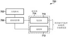
图7是包括天线阵列702的示例通信设备700的框图。在所示出的示例中,波束成形器706耦接至天线阵列702。可以是收发器714的一部分的发送器710和接收器712耦接至波束成形器706。发送器710和接收器712还可以耦接至其他组件,例如一个或更多个输入/输出装置、一个或更多个存储器装置和/或其他信号处理组件,其进一步处理所接收的信号或执行处理以生成用于通过天线阵列702在无线通信链路上传输的信号。7 is a block diagram of an
天线阵列702包括多个天线元件,例如图1至图6中的天线元件102a至102g,并且是到通信介质的物理接口的示例。天线元件可以采用如上所指出的各种形式中的任何一种,这取决于实现图7所示组件的通信设备的类型。
例如,波束成形器706包括可以如图1至图6中的任何一个所示的波束成形跟踪系统,其中接收器712耦接至图1至图6中的“到基带”连接。波束成形器206还可以包括耦接至发送器710的发送路径组件。例如,发送路径可以包括主通道数模DAC而不是ADC,以将数字发送信号转换为模拟,和/或包括上变频器而不是下变频器,以将发送信号转换为RF。可以使用各种类型的DAC电路系统或上变频电路系统中的任何一种。信号传输可以使用相同的可变相移元件106a至106g作为波束成形跟踪系统,或者使用单独的一组可变相移器。诸如可变相移元件108a至108g、110a至110g的侧通道可变相移元件可以可能地用于发送路径中,其中每个发送路径中的信号组合器将侧通道信号组合成主通道信号以通过每个天线元件传输。然而,在波束成形跟踪系统不包括主通道相移元件的实施方式中,用于发送路径的单独的一组可变相移元件可以是优选的。For example, the
虽然在图7中示为单个块,但是波束成形器706可以包括单独的接收和发送波束成形器。例如,时域双工(Time Domain Duplexing,TDD)可以用于协调单个波束成形器的接收和发送操作。单独的接收和发送波束成形器可以支持其他双工技术,例如频域双工(Frequency Domain Duplexing,FDD)。Although shown as a single block in FIG. 7,
发送器710和接收器712可以用硬件、固件或执行软件的一个或更多个组件来实现。通信设备不一定必须支持发送功能和接收功能两者,并且因此在一些实施方式中,可以仅设置发送器710或仅设置接收器712。波束成形跟踪可以与图7中的发送器710、接收器712或如收发器714中的两者结合使用。例如,波束成形跟踪可以用于将天线波束朝向远程通信设备对准。在这种波束成形跟踪期间确定的通道相移可以用于发送波束成形,以向远程通信设备发送信号。接收的信号可以仅用于波束成形跟踪,并且在波束成形跟踪仅用于天线波束对准以向远程通信设备发送信号的实施方式中,不一定需要另外处理接收的信号。
波束成形跟踪可以在用户设备或通信网络设备中实现。对于不同类型的通信设备,示例通信设备700的各种组件的实现细节可以是不同的。如上所指出的,可以在天线阵列702中实现不同类型的天线元件,这取决于示例通信设备700是用户设备还是网络设备。天线元件数目和设计不仅可以取决于天线阵列702可用的物理空间,而且还取决于或替代地取决于天线元件将被操作的频率以及无线通信链路或要提供的链路的其他特性。通信设备也可以包括多个天线阵列,例如用于不同的接收和发送频率或不同的通信链路。例如,接入网络中的网络设备可以包括用于网络侧通信链路和接入侧通信链路的不同天线阵列。波束成形器706、发送器710和接收器712中的任何一个的设计在不同类型的通信设备中也可以是不同的。Beamforming tracking can be implemented in user equipment or communication network equipment. The implementation details of the various components of
在操作中,要通过天线阵列702发送的输出信号由发送器710生成并且被提供给波束成形器706,波束成形器706控制在发送波束成形中应用的通道相移。如上所指出的,这些相移可以基于在波束成形跟踪期间用于天线波束对准的通道相移。波束成形跟踪可以应用于信号传输而不仅仅是信号接收。波束成形器706将相移的发送信号馈送到天线阵列702中的天线元件。In operation, the output signal to be transmitted by
在接收方向上,在天线阵列702的天线元件处接收的信号由波束成形器706使用用以波束成形跟踪,并且还可以由波束成形器组合以生成输入信号以供接收器712处理。In the receive direction, signals received at the antenna elements of
通信设备700可以是用户设备或通信网络设备。图8是可以实现本公开内容的实施方式的示例通信系统的框图。图8中的示例通信系统800包括接入网络802和核心网络804。接入网络802包括通过网络通信链路832、834、836进行通信的网络设备810、812、814以及通过接入通信链路838、839与所示示例中的网络设备814通信的用户设备822、824。接入网络802通过另一网络通信链路840与核心网络804进行通信。核心网络804如接入网络802那样可以包括与接入网络802中的网络设备810、812、814中的一个或更多个设施通信的网络设备。然而,在具有接入网络802和核心网络804的通信系统中,核心网络可能不自己直接向用户设备提供通信服务。The
通信系统800仅旨在用作说明性示例。接入网络802可以包括例如如图所示的可能全部彼此直接通信或者可能不全部彼此直接通信的多于或少于三个的网络设备的设施。而且,接入网络802中的多于一个的网络设备的设施可以向用户设备提供通信服务。可以存在耦接至核心网络804的多于一个的接入网络802。还应当理解,本公开内容不以任何形式限于具有接入网络/核心网络结构的通信系统。
考虑到接入网络802,各种实现方式中的任何一种都是可能的。这种网络设备为其提供通信服务的网络设备810、812、814和用户设备822、824的确切结构是与实现方式相关的。图7中的通信设备700是可以实现为网络设备810、812、814和/或用户设备822、824的通信设备的示例。Given access network 802, any of various implementations are possible. The exact structure of the
向用户设备822、824提供通信服务的至少网络设备814包括物理接口和通信电路系统,以支持通过接入链路838、839与用户设备的接入侧通信。接入侧物理接口可以是例如接入通信链路838、839为无线链路的天线或天线阵列的形式。在有线接入通信链路838、839的情况下,接入侧物理接口可以是到有线通信介质的端口或连接器。例如,可以在网络设备814处设置多个接入侧接口,以支持相同类型或不同类型的多个接入通信链路838、839。耦接至接入网络设备814处的一个或更多个接入侧物理接口的通信电路系统的类型取决于接入通信链路838、839的一个或更多个类型以及用于与用户设备822、824通信的一个或更多个通信协议。At least the
网络设备810、812、814还包括网络侧物理接口或者可能的多个网络侧物理接口,以及用于实现与接入网络802中的其他网络设备的通信的通信电路系统。网络设备810、812、814中的至少一些设施还包括一个或更多个网络侧物理接口和用于通过通信链路840实现与核心网络设备的通信的通信电路系统。网络设备810、812、814和核心网络804之间可以存在多个通信链路。接入网络802中的网络侧通信链路832、834、836和到核心网络804的通信链路840可以是相同类型的通信链路。在这种情况下,网络设备810、812、814处的相同类型的物理接口和相同的通信电路系统可以支持接入网络802内的接入网络设备之间以及接入网络802和核心网络804之间的通信。替代地,不同的物理接口和通信电路系统可以被设置在网络设备810、812、814处,用于在接入网络802内以及在接入网络802和核心网络804之间进行通信。The
核心网络804中的网络设备在结构上可以与网络设备810、812、814类似。然而,如上所指出的,核心网络804中的网络设备可能不直接向用户设备提供通信服务,并且因此可能不包括用于接入通信链路的接入侧物理接口或者相关联的接入侧通信电路系统。核心网络804中的网络设备处的物理接口和通信电路系统可以支持与接入网络802中的网络通信链路的类型相同的类型的一个或更多个网络通信链路、与接入网络802中的网络通信链路的类型不同的类型的一个或更多个网络通信链路或两者。The network devices in
正如网络设备810、812、814处的物理接口和核心网络804中的网络设备的确切结构是与实现方式相关的,相关联的通信电路系统也是与实现方式相关的。一般地,硬件、固件、执行软件的组件或其某种组合可以用于实现这样的通信电路系统。以上提供了可以适用于实现通信电路系统的电子装置的示例。Just as the physical interfaces at the
用户设备822、824的每个设施包括与网络设备814处的接入侧物理接口和通信电路系统兼容的物理接口和通信电路系统,以使用户设备能够与网络设备通信。相同类型或不同类型的多个物理接口可以被设置在用户设备822、824处。用户设备822、824还可以包括诸如输入/输出装置的组件,使用户设备的功能通过所述组件可供用户使用。例如,在诸如智能电话的无线通信装置的情况下,这些功能不仅可以包括通信功能,而且还包括不需要涉及通信的其他本地功能。不同类型的用户设备822、824例如不同的智能电话可以由相同的网络设备814服务。Each facility of the
通信链路832、834、836、838、839、840和核心网络804中的通信链路中的任何一个可以可能地为无线通信链路或包括无线通信链路。这样的通信链路趋向于更经常用于接入网络802内而非核心网络804中,尽管核心网络级的无线通信链路是可行的。可以在无线通信链路的每一端处使用包括多个天线元件的天线阵列,以使得能够进行空中通信。在一个实施方式中,本文公开的技术至少用于接入网络802中的无线回程。Any of the communication links 832, 834, 836, 838, 839, 840 and the communication links in the
以上通过示例的方式描述了各种实施方式。更一般地,波束成形跟踪设备或系统包括可变相移器112、212、312、512,以从天线阵列中的相应天线元件接收信号。每个可变相移器包括一对相移元件,该对相移元件施加与可变相移器从其接收信号的天线元件所关联的通道相移有关的相应的相移。相应的相移与相反的方向上的与天线阵列的当前天线波束方向的侧角对应。波束成形跟踪控制器126、226、426、526、626被耦接用以从可变相移器接收相移信号,并且被配置成基于相移信号生成控制信号以控制通道相移。波束成形跟踪可以是一维或多维的。Various embodiments have been described above by way of example. More generally, a beamforming tracking device or system includes
在实施方式中,波束成形跟踪控制器126、226、426、526、626被配置成确定对于已经向其施加与第一侧角对应的相移的相移信号还是对于已经向其施加与第二侧角对应的相移的相移信号的频谱函数具有更大的值。基于该确定生成控制信号。频谱函数的示例包括用于幂律跟踪的信号功率以及用于AoA梯度跟踪的AoA梯度。In an embodiment, the
控制信号控制通道相移以与通过基于相移信号具有较大的频谱函数值的侧角的跟踪角来调整的当前天线波束方向对应。The control signal controls the channel phase shift to correspond to the current antenna beam direction adjusted by the tracking angle based on the side angle for which the phase shifted signal has a larger spectral function value.
对于一维波束成形跟踪,如果已经向其施加与第一侧角对应的相移的相移信号具有较大的频谱函数值,则控制通道相移以通过第一侧角的方向上的跟踪角调整天线波束方向。类似地,如果已经向其施加与第二侧角对应的相移的相移信号具有较大的频谱函数值,则控制通道相移以通过第二侧角的方向上的跟踪角调整天线波束方向。For one-dimensional beamforming tracking, if the phase-shifted signal to which the phase shift corresponding to the first side angle has been applied has a larger spectral function value, the channel phase shift is controlled to pass the tracking angle in the direction of the first side angle Adjust the antenna beam direction. Similarly, if the phase shifted signal to which the phase shift corresponding to the second side angle has been applied has a larger spectral function value, the channel phase shift is controlled to adjust the antenna beam direction by the tracking angle in the direction of the second side angle .
在二维波束成形跟踪中,有四个方向。可以基于所有四个方向中的总体最高频谱函数值来控制通道相移。上述水平和竖直梯度幂律跟踪机制中的跟踪角可能不一定与侧角之一在同一方向上,但是跟踪角方向仍然基于相移信号具有较大频谱函数值的侧角,频谱函数是梯度幂律跟踪中的信号功率。In 2D beamforming tracking, there are four directions. The channel phase shift can be controlled based on the overall highest spectral function value in all four directions. The tracking angle in the above horizontal and vertical gradient power-law tracking mechanisms may not necessarily be in the same direction as one of the side angles, but the tracking angle direction is still based on the side angle where the phase-shifted signal has a larger value of the spectral function, which is the gradient Signal power in power-law tracking.
在图1和图3至图6中,每个可变相移器包括施加通道相移的可变相移元件,并且一对相移元件耦接至可变相移元件。在图2中,每个可变相移器的一对相移元件包括一对可变相移元件。In FIGS. 1 and 3-6, each variable phase shifter includes a variable phase shift element that applies a channel phase shift, and a pair of phase shift elements are coupled to the variable phase shift element. In FIG. 2, a pair of phase shift elements of each variable phase shifter includes a pair of variable phase shift elements.
在一些实施方式中,可以设置LNA、下变频器、ADC和/或信号组合器。例如,第一下变频器可以耦接至跟踪控制器并且耦接至可变相移器的、施加与第一方向上的第一侧角对应的相移的相移元件,并且第二下变频器可以耦接至跟踪控制器并且耦接至可变相移器的、施加与不同于第一方向的第二方向上的第二侧角对应的相移的相移元件。这些作为示例示出为图1至图4中的侧通道或侧通道下变频器114、118。诸如图1中的116的第三下变频器可以耦接至跟踪控制器和可变相移器。In some embodiments, LNAs, downconverters, ADCs and/or signal combiners may be provided. For example, a first downconverter may be coupled to the tracking controller and to a phase shifting element of a variable phase shifter that applies a phase shift corresponding to a first side angle in the first direction, and a second downconverter A phase shift element, which may be coupled to the tracking controller and to the variable phase shifter, applies a phase shift corresponding to a second side angle in a second direction different from the first direction. These are shown by way of example as side channel or
ADC可以类似地耦接在侧通道路径和主通道路径中,如图1至图4所示。ADC或在一些实施方式中信号组合器可以提供数字输出以供接收器处理。ADCs may be similarly coupled in the side channel path and the main channel path, as shown in FIGS. 1-4 . The ADC or in some embodiments the signal combiner may provide a digital output for processing by the receiver.
通信设备可包括天线阵列、可变相移器和波束成形跟踪控制器。可变相移器和波束成形跟踪控制器可以实现一维或多维波束成形跟踪。The communication device may include an antenna array, a variable phase shifter, and a beamforming tracking controller. The variable phase shifter and beamforming tracking controller can achieve one-dimensional or multi-dimensional beamforming tracking.
上面参照图1至图8描述的实施方式涉及设备或系统。还设想了方法。图9是示例波束成形跟踪方法的流程图。The embodiments described above with reference to Figures 1 to 8 relate to devices or systems. Methods are also envisaged. 9 is a flowchart of an example beamforming tracking method.
在902处,从天线阵列中的天线元件接收信号。在904处,向所接收的信号施加通道相移。在906、908处,向从天线元件中的每一个接收的信号施加与通道相移有关的相应的相移。“+δ”和“-δ”相移对应于与相反的方向上的与用于一维波束成形跟踪的天线阵列的当前天线波束方向的+δ和-δ侧角。对于二维波束成形跟踪,存在分别与四个跟踪方向对应的四个相移。图9中并行示出了906、908处的相移,以示出例如使用在单独的信号扫描时隙中接收的信号在同一时间而不是不同时间将侧角相移施加至相同的接收的信号。At 902, signals are received from antenna elements in an antenna array. At 904, a channel phase shift is applied to the received signal. At 906, 908, a respective phase shift related to the channel phase shift is applied to the signal received from each of the antenna elements. The "+δ" and "-δ" phase shifts correspond to the +δ and -δ side angles in opposite directions from the current antenna beam direction of the antenna array used for one-dimensional beamforming tracking. For two-dimensional beamforming tracking, there are four phase shifts corresponding to the four tracking directions, respectively. The phase shifts at 906, 908 are shown in parallel in FIG. 9 to illustrate the application of side angle phase shifts to the same received signal at the same time rather than at different times, eg using the signal received in separate signal scanning time slots .
在910处生成基于来自906、908处的相移操作的相移信号的控制信号,以控制将被施加至随后在902处从天线元件接收的信号的通道相移。Control signals based on the phase-shifted signals from the phase-shift operations at 906 , 908 are generated at 910 to control the channel phase shift to be applied to signals subsequently received at 902 from the antenna elements.
示例方法900示出了一个实施方式。在其他实施方式中,可以以类似或不同的顺序执行类似或不同的操作。本文描述了执行所示出的操作的各种方式以及可以执行的其他操作的示例。
例如,尽管在904和906、908处示出了单独的相移操作,但是可以利用侧角相移来执行通道相移,如图2中的设备实施方式中那样。在图9所示的实施方式中,在906、908处向在904处已经向其施加通道相移的相移信号施加侧角相移。相移可以替代地涉及向在902处从天线元件中的每一个接收的信号施加:与通道相移加上δ相移对应的第一相移和与通道相移减去δ相移对应的第二相移。对于两个侧角,δ相移可以具有相同的大小,如图1至图4所示,或者在其他实施方式中可以具有不同的大小。For example, although separate phase shifting operations are shown at 904 and 906, 908, channel phase shifting may be performed using side angle phase shifting, as in the device embodiment in FIG. In the embodiment shown in FIG. 9 , a side angle phase shift is applied at 906 , 908 to the phase shifted signal to which the channel phase shift has been applied at 904 . The phase shift may alternatively involve applying to the signal received at 902 from each of the antenna elements: a first phase shift corresponding to the channel phase shift plus the delta phase shift and a first phase shift corresponding to the channel phase shift minus the delta phase shift. Two phase shift. The delta phase shifts may be of the same magnitude for both side angles, as shown in Figures 1-4, or may be of different magnitudes in other embodiments.
在910处生成控制信号可以涉及确定对于已经向其施加与第一侧角对应的相移的相移信号还是对于已经向其施加与第二侧角对应的相移的相移信号的频谱函数例如信号功率或AoA梯度具有较大值。控制信号控制通道相移以与通过基于相移信号具有较大的频谱函数值的侧角的跟踪角来调整的当前天线波束方向对应。一维波束成形跟踪涉及两个侧角,并且二维波束成形跟踪涉及四个侧角。Generating the control signal at 910 may involve determining a spectral function for the phase shifted signal to which a phase shift corresponding to the first flank angle has been applied or for the phase shift signal to which a phase shift corresponding to the second flank angle has been applied, eg The signal power or AoA gradient has a larger value. The control signal controls the channel phase shift to correspond to the current antenna beam direction adjusted by the tracking angle based on the side angle for which the phase shifted signal has a larger spectral function value. One-dimensional beamforming tracking involves two side angles, and two-dimensional beamforming tracking involves four side angles.
对于一维幂律跟踪,将已经向其施加了与第一侧角对应的相移的相移信号的信号功率与已经向其施加了与第二侧角对应的相移的相移信号的信号功率进行比较。如上所指出的,还可以与当前天线波束方向的主通道信号的信号功率进行比较。对于AoA梯度跟踪,比较涉及AoA梯度。For one-dimensional power-law tracking, compare the signal power of the phase-shifted signal to which the phase shift corresponding to the first side angle has been applied to the signal of the phase-shift signal to which the phase shift corresponding to the second side angle has been applied power for comparison. As indicated above, a comparison can also be made with the signal power of the main channel signal for the current antenna beam direction. For AoA gradient tracking, the comparison involves AoA gradients.
上面描述了用于二维波束成形跟踪的控制信号生成的示例。An example of control signal generation for two-dimensional beamforming tracking is described above.
在一些实施方式中,可以执行附加操作。例如,可以对相移信号进行下变频、从模拟转换为数字和/或如上所述进行组合。一些实施方式还可以提供或替代地提供多维波束成形跟踪。In some implementations, additional operations may be performed. For example, the phase shifted signal may be downconverted, converted from analog to digital, and/or combined as described above. Some embodiments may also or alternatively provide multi-dimensional beamforming tracking.
例如,根据设备和系统图和描述,其他变化可以是明显的或变得明显。For example, other changes may be apparent or apparent from the device and system diagrams and descriptions.
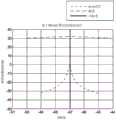
图10至图12是模拟结果的示例图。图10至图12中的示例曲线图涉及24个天线元件的一维均匀线性阵列,其中相邻天线元件之间具有λ/2的间隔。对于模拟,为每个RF波束成形分支添加均匀的并且在0到20度内的随机相位误差。10 to 12 are example graphs of simulation results. The example graphs in Figures 10-12 involve a one-dimensional uniform linear array of 24 antenna elements with a spacing of λ/2 between adjacent antenna elements. For the simulation, a random phase error that is uniform and within 0 to 20 degrees is added to each RF beamforming branch.
图10示出了用于-45度的当前天线波束指向角和-47度的实际到达方向的AoA梯度方法和幂律方法两者的频谱函数。用于AoA梯度方法和幂律方法两者的频谱函数将导致在该示例中天线波束被朝向实际的到达方向向左重新对准。Figure 10 shows the spectral functions for both the AoA gradient method and the power law method for a current antenna beam pointing angle of -45 degrees and an actual direction of arrival of -47 degrees. The spectral functions for both the AoA gradient method and the power-law method will result in the antenna beam being realigned to the left towards the actual direction of arrival in this example.
关于AoA梯度轨迹,频谱函数差异不如图10所示的标度中的幂律轨迹那样明显。这些差异在可以用于基于AoA梯度方法的波束成形跟踪的不同的尺度上会更加突出。Regarding the AoA gradient trajectories, the spectral function differences are not as pronounced as the power-law trajectories in the scale shown in Figure 10. These differences are accentuated at different scales that can be used for AoA gradient based beamforming tracking.
对于幂律轨迹,功率向左增加刚刚超过1度的侧角,并且然后达到峰值并且开始减小。在设置δ/侧角时可以确定并考虑这些特性。For a power-law trajectory, the power increases to the left by just over a 1-degree side angle, and then peaks and begins to decrease. These properties can be determined and taken into account when setting the delta/side angle.
图11示出了当天线波束与到达方向对准时侧角的AoA梯度和幂律轨迹。在这两种情况下,频谱函数在到达方向处达到峰值。Figure 11 shows the AoA gradient and power-law locus of the side angle when the antenna beam is aligned with the direction of arrival. In both cases, the spectral function peaks at the direction of arrival.
图12示出了信号功率与方位角的关系,并且比较了用于组合两个侧信号的天线方向图和使用主通道路径而不进行信号组合的天线方向图。在所示的示例中,信号组合或加窗抑制旁瓣。在该示例中存在一些主瓣抑制,为约3dB,但是旁瓣抑制必须更加显著,为约10dB。Figure 12 shows signal power versus azimuth and compares the antenna pattern used to combine the two side signals and the antenna pattern using the main channel path without signal combining. In the example shown, signal combining or windowing suppresses side lobes. There is some mainlobe suppression in this example, about 3dB, but the sidelobe suppression has to be more significant, about 10dB.
图10至图12中的示例曲线图仅用于说明目的。在类似或不同的模拟条件下和/或在操作期间,可以观察到不同的结果。The example graphs in Figures 10-12 are for illustration purposes only. Different results may be observed under similar or different simulated conditions and/or during operation.
已经描述的内容仅仅是对本公开内容的实施方式的原理的应用的说明。可以由本领域技术人员实现其他布置和方法。尽管本公开内容涉及特定特征和实施方式,但是可以进行各种修改和组合。因此,说明书和附图要被仅认为是如由所附权利要求限定的本发明的实施方式的说明,并且被设想成涵盖任何和所有的修改、变化、组合或等效方案。因此,应该理解的是,在不脱离由所附权利要求限定的本发明的情况下,可以进行各种改变、替换和变更。What has been described is merely illustrative of the application of the principles of the embodiments of the present disclosure. Other arrangements and methods can be implemented by those skilled in the art. Although this disclosure is directed to specific features and embodiments, various modifications and combinations are possible. Accordingly, the specification and drawings are to be regarded as illustrative only of embodiments of the invention as defined by the appended claims, and are intended to cover any and all modifications, variations, combinations or equivalents. Therefore, it should be understood that various changes, substitutions and alterations can be made herein without departing from the invention as defined by the appended claims.
此外,本申请的范围并不旨在限于说明书中描述的任何过程、机器、制造品、合成物、装置、方法和步骤的特定实施方式。如本领域普通技术人员将根据本公开内容易于理解的,可以利用现有或随后开发的过程、机器、制造品、合成物、装置、方法或步骤,其执行与本文公开的对应的实施方式基本上相同的功能或实现与本文公开的对应的实施方式基本上相同的结果。因此,所附权利要求旨在将这样的过程、机器、制造品、合成物、装置、方法或步骤包括在它们的范围内。Furthermore, the scope of this application is not intended to be limited to the particular embodiments of any process, machine, article of manufacture, composition, means, method and steps described in the specification. As will be readily understood by those of ordinary skill in the art in light of this disclosure, existing or subsequently developed processes, machines, articles of manufacture, compositions, devices, methods, or steps may be utilized that perform substantially the same as the corresponding embodiments disclosed herein. perform substantially the same functions or achieve substantially the same results as the corresponding embodiments disclosed herein. Accordingly, the appended claims are intended to include within their scope such processes, machines, articles of manufacture, compositions, means, methods, or steps.
例如,附图示出了说明性示例实施方式。本文公开的技术不仅仅限于这些实施方式。其他实施方式可以包括以类似或不同顺序互连的类似或不同的组件。组件的数目也可以或替代地在不同的实施方式之间变化。例如,一维波束成形跟踪控制系统可以包括多对侧角相移元件,以使得能够在每个方向上同时扫描多个侧角。For example, the accompanying drawings show illustrative example embodiments. The techniques disclosed herein are not limited only to these embodiments. Other implementations may include similar or different components interconnected in a similar or different order. The number of components may also or alternatively vary from implementation to implementation. For example, a one-dimensional beamforming tracking control system may include multiple pairs of side angle phase shifting elements to enable simultaneous scanning of multiple side angles in each direction.
还应该理解,在不同的实施方式中,其他实现方式细节可以是不同的。例如,侧角不一定必须关于当前天线波束方向对称。例如,如果天线波束已经在若干跟踪周期中在该方向(例如右或左)上重新对准,则可以增加一个方向上的侧角。在二维波束成形扫描中,相同或不同的侧角可以类似地用于在不同取向上扫描。虽然预期所有侧角在许多实现方式中将具有共同的值,但是在一些实施方式中可以使用不同的侧角。It should also be understood that other implementation details may vary from implementation to implementation. For example, the side angle does not necessarily have to be symmetrical with respect to the current antenna beam direction. For example, if the antenna beam has been realigned in that direction (eg, right or left) over several tracking cycles, the side angle in one direction can be increased. In two-dimensional beamforming scans, the same or different side angles can similarly be used to scan in different orientations. While it is expected that all side angles will have a common value in many implementations, different side angles may be used in some implementations.
而且,虽然主要在方法和系统的上下文中进行了描述,但是也可以设想其他实现方式,例如以非暂态处理器可读介质上存储的指令的形式。这是对软件产品形式的实施方式的说明。更一般地,软件产品可以被存储在非易失性或非暂态存储介质中,其可以以一个或更多个存储器装置的形式实现,包括固态存储器装置和/或具有可移动并且甚至可能可移除的存储介质的存储器装置。存储器装置的示例包括致密盘只读存储器(compact diskread-only memory,CD-ROM)、通用串行总线(Universal Serial Bus,USB)闪存盘和可移动硬盘。软件产品包括存储在存储介质上的多个指令,其使得处理器或计算机装置(例如个人计算机、服务器、网络装置)能够执行如本文所公开的方法。Also, although primarily described in the context of methods and systems, other implementations are also contemplated, such as in the form of instructions stored on a non-transitory processor-readable medium. This is an illustration of an implementation in the form of a software product. More generally, a software product may be stored in a non-volatile or non-transitory storage medium, which may be implemented in the form of one or more memory devices, including solid-state memory devices and/or with removable and possibly even removable The memory device of the removed storage medium. Examples of memory devices include compact disk read-only memory (CD-ROM), Universal Serial Bus (USB) flash drives, and removable hard disks. A software product includes a plurality of instructions stored on a storage medium that enable a processor or computer device (eg, personal computer, server, network device) to perform the methods as disclosed herein.
Claims (19)
Translated fromChineseApplications Claiming Priority (3)
| Application Number | Priority Date | Filing Date | Title |
|---|---|---|---|
| US15/184,006US10297915B2 (en) | 2016-06-16 | 2016-06-16 | Apparatus and methods for beamforming tracking |
| US15/184,006 | 2016-06-16 | ||
| PCT/CN2016/091048WO2017215078A1 (en) | 2016-06-16 | 2016-07-22 | Apparatus and methods for beamforming tracking |
Publications (2)
| Publication Number | Publication Date |
|---|---|
| CN109075458A CN109075458A (en) | 2018-12-21 |
| CN109075458Btrue CN109075458B (en) | 2020-09-11 |
Family
ID=60659825
Family Applications (1)
| Application Number | Title | Priority Date | Filing Date |
|---|---|---|---|
| CN201680083078.1AActiveCN109075458B (en) | 2016-06-16 | 2016-07-22 | Apparatus and method for beamforming tracking |
Country Status (4)
| Country | Link |
|---|---|
| US (1) | US10297915B2 (en) |
| EP (1) | EP3417512B1 (en) |
| CN (1) | CN109075458B (en) |
| WO (1) | WO2017215078A1 (en) |
Families Citing this family (8)
| Publication number | Priority date | Publication date | Assignee | Title |
|---|---|---|---|---|
| US20180212590A1 (en)* | 2017-01-24 | 2018-07-26 | Psemi Corporation | Glitch Mitigation in Switched Reactance Phase Shifters |
| DE102018116337A1 (en)* | 2018-07-05 | 2020-01-09 | Auma Riester Gmbh & Co. Kg | actuator |
| WO2020131374A1 (en)* | 2018-12-18 | 2020-06-25 | Commscope Technologies Llc | Small cell wireless communication devices having enhanced beamsteering capability and methods of operating same |
| US11937328B2 (en) | 2020-03-13 | 2024-03-19 | Apple Inc. | Millimeter wave link reliability and power efficiency improvements using sensor input |
| JP7524607B2 (en)* | 2020-05-27 | 2024-07-30 | 富士通株式会社 | Wireless devices |
| JP7647297B2 (en) | 2021-04-26 | 2025-03-18 | 富士通株式会社 | Radio signal processing circuit and radio device |
| CN116014457A (en) | 2021-10-21 | 2023-04-25 | 深圳富泰宏精密工业有限公司 | Antenna system and wireless communication device with same |
| TWI832108B (en)* | 2021-10-21 | 2024-02-11 | 群邁通訊股份有限公司 | Wireless communication device |
Citations (2)
| Publication number | Priority date | Publication date | Assignee | Title |
|---|---|---|---|---|
| JPH07318627A (en)* | 1994-05-24 | 1995-12-08 | Mitsubishi Electric Corp | Satellite data receiver |
| JP2006074191A (en)* | 2004-08-31 | 2006-03-16 | Yagi Antenna Co Ltd | Phased array antenna system |
Family Cites Families (8)
| Publication number | Priority date | Publication date | Assignee | Title |
|---|---|---|---|---|
| US4639732A (en)* | 1985-02-22 | 1987-01-27 | Allied Corporation | Integral monitor system for circular phased array antenna |
| JP3441326B2 (en) | 1997-01-14 | 2003-09-02 | 株式会社東芝 | Radar equipment |
| US6791507B2 (en) | 2003-02-13 | 2004-09-14 | Telefonaktiebolaget Lm Ericsson (Publ) | Feed network for simultaneous generation of narrow and wide beams with a rotational-symmetric antenna |
| FI20065841A0 (en) | 2006-12-21 | 2006-12-21 | Nokia Corp | Communication method and systems |
| EP2009103A1 (en)* | 2007-03-16 | 2008-12-31 | Ebewe Pharma Ges.m.b.H. Nfg. KG | Neurotrophic peptides |
| US8362954B2 (en)* | 2008-02-29 | 2013-01-29 | Omron Corporation | Array antenna, tag communication device, tag communication system, and beam control method for array antenna |
| US8203483B2 (en) | 2008-03-13 | 2012-06-19 | Cubic Corporation | Digital beamforming antenna and datalink array |
| US9444140B2 (en) | 2012-05-23 | 2016-09-13 | Intel Corporation | Multi-element antenna beam forming configurations for millimeter wave systems |
- 2016
- 2016-06-16USUS15/184,006patent/US10297915B2/enactiveActive
- 2016-07-22EPEP16905191.9Apatent/EP3417512B1/enactiveActive
- 2016-07-22CNCN201680083078.1Apatent/CN109075458B/enactiveActive
- 2016-07-22WOPCT/CN2016/091048patent/WO2017215078A1/ennot_activeCeased
Patent Citations (2)
| Publication number | Priority date | Publication date | Assignee | Title |
|---|---|---|---|---|
| JPH07318627A (en)* | 1994-05-24 | 1995-12-08 | Mitsubishi Electric Corp | Satellite data receiver |
| JP2006074191A (en)* | 2004-08-31 | 2006-03-16 | Yagi Antenna Co Ltd | Phased array antenna system |
Also Published As
| Publication number | Publication date |
|---|---|
| US10297915B2 (en) | 2019-05-21 |
| WO2017215078A1 (en) | 2017-12-21 |
| US20170365925A1 (en) | 2017-12-21 |
| EP3417512A4 (en) | 2019-03-13 |
| EP3417512A1 (en) | 2018-12-26 |
| EP3417512B1 (en) | 2022-04-06 |
| CN109075458A (en) | 2018-12-21 |
Similar Documents
| Publication | Publication Date | Title |
|---|---|---|
| CN109075458B (en) | Apparatus and method for beamforming tracking | |
| US11601183B2 (en) | Spatial redistributors and methods of redistributing mm-wave signals | |
| EP3480947B1 (en) | Phased array amplifier linearization | |
| JP6116126B2 (en) | Radar equipment | |
| US6992622B1 (en) | Wireless communication method and antenna system for determining direction of arrival information to form a three-dimensional beam used by a transceiver | |
| US20190212411A1 (en) | Method and apparatus for estimating direction of arrival using generation of virtual received signals | |
| CN107817392B (en) | System and method for characterizing a multi-element antenna | |
| CN110967671A (en) | Radar devices, moving objects and stationary objects | |
| US20200227824A1 (en) | Antenna apparatus with switches for antenna array calibration | |
| US9294176B2 (en) | Transmitter | |
| EP3713081B1 (en) | Phase shift module with an enhanced frequency multiplier and temperature compensation in local oscillator path | |
| EP3920333B1 (en) | Systems and methods for calibrating arrays of dual-polarization antenna elements | |
| Aoki et al. | Inter-stream loopback calibration for 5G phased-array systems | |
| US11431400B2 (en) | Method and apparatus for forming a plurality of beamformed signals using a plurality of received signals | |
| CN112305517B (en) | Analog-digital mixed multi-beam receiving array system with columnar omnibearing coverage | |
| Maletic et al. | A Software-Defined Radio Solution for Integrated mmWAVE Communication and Sensing | |
| Codau et al. | Experimental evaluation of a beamforming-capable system using NI USRP software defined radios | |
| Liao et al. | A beam switching array antenna for direction‐of‐arrival applications | |
| Baig et al. | Improved receiver architecture for digital beamforming systems | |
| Ghunney et al. | Impact of wrong beam selection on beam pair scanning method for user discovery in mmwave systems | |
| CN107621623B (en) | Signal direction detection method and beam former using same | |
| Wang et al. | Interpolation based wideband beamforming architecture | |
| KR102337200B1 (en) | Method and apparatus for forming a plurality of beamformed signals using a plurality of received signals | |
| Wang et al. | A simple beamforming network for 802.11 b/g WLAN systems | |
| Khalil et al. | Low-Cost High-Precision Direction of Arrival Estimation Using Dual-Channel Receivers SDR |
Legal Events
| Date | Code | Title | Description |
|---|---|---|---|
| PB01 | Publication | ||
| PB01 | Publication | ||
| SE01 | Entry into force of request for substantive examination | ||
| SE01 | Entry into force of request for substantive examination | ||
| GR01 | Patent grant | ||
| GR01 | Patent grant |