CN109069842B - Medical device housing with weld joint features - Google Patents
Medical device housing with weld joint featuresDownload PDFInfo
- Publication number
- CN109069842B CN109069842BCN201780023937.2ACN201780023937ACN109069842BCN 109069842 BCN109069842 BCN 109069842BCN 201780023937 ACN201780023937 ACN 201780023937ACN 109069842 BCN109069842 BCN 109069842B
- Authority
- CN
- China
- Prior art keywords
- side wall
- section
- wall
- sidewall
- weld joint
- Prior art date
- Legal status (The legal status is an assumption and is not a legal conclusion. Google has not performed a legal analysis and makes no representation as to the accuracy of the status listed.)
- Active
Links
Images


Classifications
- A—HUMAN NECESSITIES
- A61—MEDICAL OR VETERINARY SCIENCE; HYGIENE
- A61N—ELECTROTHERAPY; MAGNETOTHERAPY; RADIATION THERAPY; ULTRASOUND THERAPY
- A61N1/00—Electrotherapy; Circuits therefor
- A61N1/18—Applying electric currents by contact electrodes
- A61N1/32—Applying electric currents by contact electrodes alternating or intermittent currents
- A61N1/36—Applying electric currents by contact electrodes alternating or intermittent currents for stimulation
- A61N1/372—Arrangements in connection with the implantation of stimulators
- A61N1/375—Constructional arrangements, e.g. casings
- H—ELECTRICITY
- H05—ELECTRIC TECHNIQUES NOT OTHERWISE PROVIDED FOR
- H05K—PRINTED CIRCUITS; CASINGS OR CONSTRUCTIONAL DETAILS OF ELECTRIC APPARATUS; MANUFACTURE OF ASSEMBLAGES OF ELECTRICAL COMPONENTS
- H05K5/00—Casings, cabinets or drawers for electric apparatus
- H05K5/02—Details
- H05K5/0217—Mechanical details of casings
- A—HUMAN NECESSITIES
- A61—MEDICAL OR VETERINARY SCIENCE; HYGIENE
- A61B—DIAGNOSIS; SURGERY; IDENTIFICATION
- A61B5/00—Measuring for diagnostic purposes; Identification of persons
- A61B5/0002—Remote monitoring of patients using telemetry, e.g. transmission of vital signals via a communication network
- A61B5/0015—Remote monitoring of patients using telemetry, e.g. transmission of vital signals via a communication network characterised by features of the telemetry system
- A61B5/0022—Monitoring a patient using a global network, e.g. telephone networks, internet
- A—HUMAN NECESSITIES
- A61—MEDICAL OR VETERINARY SCIENCE; HYGIENE
- A61B—DIAGNOSIS; SURGERY; IDENTIFICATION
- A61B5/00—Measuring for diagnostic purposes; Identification of persons
- A61B5/0002—Remote monitoring of patients using telemetry, e.g. transmission of vital signals via a communication network
- A61B5/0031—Implanted circuitry
- A—HUMAN NECESSITIES
- A61—MEDICAL OR VETERINARY SCIENCE; HYGIENE
- A61B—DIAGNOSIS; SURGERY; IDENTIFICATION
- A61B5/00—Measuring for diagnostic purposes; Identification of persons
- A61B5/02—Detecting, measuring or recording for evaluating the cardiovascular system, e.g. pulse, heart rate, blood pressure or blood flow
- A61B5/0205—Simultaneously evaluating both cardiovascular conditions and different types of body conditions, e.g. heart and respiratory condition
- A—HUMAN NECESSITIES
- A61—MEDICAL OR VETERINARY SCIENCE; HYGIENE
- A61B—DIAGNOSIS; SURGERY; IDENTIFICATION
- A61B5/00—Measuring for diagnostic purposes; Identification of persons
- A61B5/02—Detecting, measuring or recording for evaluating the cardiovascular system, e.g. pulse, heart rate, blood pressure or blood flow
- A61B5/021—Measuring pressure in heart or blood vessels
- A61B5/0215—Measuring pressure in heart or blood vessels by means inserted into the body
- A—HUMAN NECESSITIES
- A61—MEDICAL OR VETERINARY SCIENCE; HYGIENE
- A61B—DIAGNOSIS; SURGERY; IDENTIFICATION
- A61B5/00—Measuring for diagnostic purposes; Identification of persons
- A61B5/02—Detecting, measuring or recording for evaluating the cardiovascular system, e.g. pulse, heart rate, blood pressure or blood flow
- A61B5/024—Measuring pulse rate or heart rate
- A61B5/02444—Details of sensor
- A—HUMAN NECESSITIES
- A61—MEDICAL OR VETERINARY SCIENCE; HYGIENE
- A61B—DIAGNOSIS; SURGERY; IDENTIFICATION
- A61B5/00—Measuring for diagnostic purposes; Identification of persons
- A61B5/68—Arrangements of detecting, measuring or recording means, e.g. sensors, in relation to patient
- A61B5/6846—Arrangements of detecting, measuring or recording means, e.g. sensors, in relation to patient specially adapted to be brought in contact with an internal body part, i.e. invasive
- A61B5/6847—Arrangements of detecting, measuring or recording means, e.g. sensors, in relation to patient specially adapted to be brought in contact with an internal body part, i.e. invasive mounted on an invasive device
- A61B5/686—Permanently implanted devices, e.g. pacemakers, other stimulators, biochips
- G—PHYSICS
- G16—INFORMATION AND COMMUNICATION TECHNOLOGY [ICT] SPECIALLY ADAPTED FOR SPECIFIC APPLICATION FIELDS
- G16H—HEALTHCARE INFORMATICS, i.e. INFORMATION AND COMMUNICATION TECHNOLOGY [ICT] SPECIALLY ADAPTED FOR THE HANDLING OR PROCESSING OF MEDICAL OR HEALTHCARE DATA
- G16H40/00—ICT specially adapted for the management or administration of healthcare resources or facilities; ICT specially adapted for the management or operation of medical equipment or devices
- G16H40/60—ICT specially adapted for the management or administration of healthcare resources or facilities; ICT specially adapted for the management or operation of medical equipment or devices for the operation of medical equipment or devices
- G16H40/67—ICT specially adapted for the management or administration of healthcare resources or facilities; ICT specially adapted for the management or operation of medical equipment or devices for the operation of medical equipment or devices for remote operation
- A—HUMAN NECESSITIES
- A61—MEDICAL OR VETERINARY SCIENCE; HYGIENE
- A61B—DIAGNOSIS; SURGERY; IDENTIFICATION
- A61B5/00—Measuring for diagnostic purposes; Identification of persons
- A61B5/103—Measuring devices for testing the shape, pattern, colour, size or movement of the body or parts thereof, for diagnostic purposes
- A61B5/11—Measuring movement of the entire body or parts thereof, e.g. head or hand tremor or mobility of a limb
- A—HUMAN NECESSITIES
- A61—MEDICAL OR VETERINARY SCIENCE; HYGIENE
- A61N—ELECTROTHERAPY; MAGNETOTHERAPY; RADIATION THERAPY; ULTRASOUND THERAPY
- A61N1/00—Electrotherapy; Circuits therefor
- A61N1/18—Applying electric currents by contact electrodes
- A61N1/32—Applying electric currents by contact electrodes alternating or intermittent currents
- A61N1/36—Applying electric currents by contact electrodes alternating or intermittent currents for stimulation
- A61N1/362—Heart stimulators
- A61N1/365—Heart stimulators controlled by a physiological parameter, e.g. heart potential
- A61N1/36514—Heart stimulators controlled by a physiological parameter, e.g. heart potential controlled by a physiological quantity other than heart potential, e.g. blood pressure
- A61N1/36521—Heart stimulators controlled by a physiological parameter, e.g. heart potential controlled by a physiological quantity other than heart potential, e.g. blood pressure the parameter being derived from measurement of an electrical impedance
- A—HUMAN NECESSITIES
- A61—MEDICAL OR VETERINARY SCIENCE; HYGIENE
- A61N—ELECTROTHERAPY; MAGNETOTHERAPY; RADIATION THERAPY; ULTRASOUND THERAPY
- A61N1/00—Electrotherapy; Circuits therefor
- A61N1/18—Applying electric currents by contact electrodes
- A61N1/32—Applying electric currents by contact electrodes alternating or intermittent currents
- A61N1/36—Applying electric currents by contact electrodes alternating or intermittent currents for stimulation
- A61N1/362—Heart stimulators
- A61N1/365—Heart stimulators controlled by a physiological parameter, e.g. heart potential
- A61N1/36514—Heart stimulators controlled by a physiological parameter, e.g. heart potential controlled by a physiological quantity other than heart potential, e.g. blood pressure
- A61N1/36535—Heart stimulators controlled by a physiological parameter, e.g. heart potential controlled by a physiological quantity other than heart potential, e.g. blood pressure controlled by body position or posture
- A—HUMAN NECESSITIES
- A61—MEDICAL OR VETERINARY SCIENCE; HYGIENE
- A61N—ELECTROTHERAPY; MAGNETOTHERAPY; RADIATION THERAPY; ULTRASOUND THERAPY
- A61N1/00—Electrotherapy; Circuits therefor
- A61N1/18—Applying electric currents by contact electrodes
- A61N1/32—Applying electric currents by contact electrodes alternating or intermittent currents
- A61N1/36—Applying electric currents by contact electrodes alternating or intermittent currents for stimulation
- A61N1/362—Heart stimulators
- A61N1/365—Heart stimulators controlled by a physiological parameter, e.g. heart potential
- A61N1/36514—Heart stimulators controlled by a physiological parameter, e.g. heart potential controlled by a physiological quantity other than heart potential, e.g. blood pressure
- A61N1/36542—Heart stimulators controlled by a physiological parameter, e.g. heart potential controlled by a physiological quantity other than heart potential, e.g. blood pressure controlled by body motion, e.g. acceleration
- A—HUMAN NECESSITIES
- A61—MEDICAL OR VETERINARY SCIENCE; HYGIENE
- A61N—ELECTROTHERAPY; MAGNETOTHERAPY; RADIATION THERAPY; ULTRASOUND THERAPY
- A61N1/00—Electrotherapy; Circuits therefor
- A61N1/18—Applying electric currents by contact electrodes
- A61N1/32—Applying electric currents by contact electrodes alternating or intermittent currents
- A61N1/36—Applying electric currents by contact electrodes alternating or intermittent currents for stimulation
- A61N1/362—Heart stimulators
- A61N1/365—Heart stimulators controlled by a physiological parameter, e.g. heart potential
- A61N1/36514—Heart stimulators controlled by a physiological parameter, e.g. heart potential controlled by a physiological quantity other than heart potential, e.g. blood pressure
- A61N1/3655—Heart stimulators controlled by a physiological parameter, e.g. heart potential controlled by a physiological quantity other than heart potential, e.g. blood pressure controlled by body or blood temperature
- A—HUMAN NECESSITIES
- A61—MEDICAL OR VETERINARY SCIENCE; HYGIENE
- A61N—ELECTROTHERAPY; MAGNETOTHERAPY; RADIATION THERAPY; ULTRASOUND THERAPY
- A61N1/00—Electrotherapy; Circuits therefor
- A61N1/18—Applying electric currents by contact electrodes
- A61N1/32—Applying electric currents by contact electrodes alternating or intermittent currents
- A61N1/36—Applying electric currents by contact electrodes alternating or intermittent currents for stimulation
- A61N1/362—Heart stimulators
- A61N1/365—Heart stimulators controlled by a physiological parameter, e.g. heart potential
- A61N1/36514—Heart stimulators controlled by a physiological parameter, e.g. heart potential controlled by a physiological quantity other than heart potential, e.g. blood pressure
- A61N1/36564—Heart stimulators controlled by a physiological parameter, e.g. heart potential controlled by a physiological quantity other than heart potential, e.g. blood pressure controlled by blood pressure
- A—HUMAN NECESSITIES
- A61—MEDICAL OR VETERINARY SCIENCE; HYGIENE
- A61N—ELECTROTHERAPY; MAGNETOTHERAPY; RADIATION THERAPY; ULTRASOUND THERAPY
- A61N1/00—Electrotherapy; Circuits therefor
- A61N1/18—Applying electric currents by contact electrodes
- A61N1/32—Applying electric currents by contact electrodes alternating or intermittent currents
- A61N1/36—Applying electric currents by contact electrodes alternating or intermittent currents for stimulation
- A61N1/362—Heart stimulators
- A61N1/365—Heart stimulators controlled by a physiological parameter, e.g. heart potential
- A61N1/36514—Heart stimulators controlled by a physiological parameter, e.g. heart potential controlled by a physiological quantity other than heart potential, e.g. blood pressure
- A61N1/36578—Heart stimulators controlled by a physiological parameter, e.g. heart potential controlled by a physiological quantity other than heart potential, e.g. blood pressure controlled by mechanical motion of the heart wall, e.g. measured by an accelerometer or microphone
- A—HUMAN NECESSITIES
- A61—MEDICAL OR VETERINARY SCIENCE; HYGIENE
- A61N—ELECTROTHERAPY; MAGNETOTHERAPY; RADIATION THERAPY; ULTRASOUND THERAPY
- A61N1/00—Electrotherapy; Circuits therefor
- A61N1/18—Applying electric currents by contact electrodes
- A61N1/32—Applying electric currents by contact electrodes alternating or intermittent currents
- A61N1/36—Applying electric currents by contact electrodes alternating or intermittent currents for stimulation
- A61N1/372—Arrangements in connection with the implantation of stimulators
- A61N1/375—Constructional arrangements, e.g. casings
- A61N1/37512—Pacemakers
- A—HUMAN NECESSITIES
- A61—MEDICAL OR VETERINARY SCIENCE; HYGIENE
- A61N—ELECTROTHERAPY; MAGNETOTHERAPY; RADIATION THERAPY; ULTRASOUND THERAPY
- A61N1/00—Electrotherapy; Circuits therefor
- A61N1/18—Applying electric currents by contact electrodes
- A61N1/32—Applying electric currents by contact electrodes alternating or intermittent currents
- A61N1/36—Applying electric currents by contact electrodes alternating or intermittent currents for stimulation
- A61N1/372—Arrangements in connection with the implantation of stimulators
- A61N1/375—Constructional arrangements, e.g. casings
- A61N1/3752—Details of casing-lead connections
- A61N1/3754—Feedthroughs
- A—HUMAN NECESSITIES
- A61—MEDICAL OR VETERINARY SCIENCE; HYGIENE
- A61N—ELECTROTHERAPY; MAGNETOTHERAPY; RADIATION THERAPY; ULTRASOUND THERAPY
- A61N1/00—Electrotherapy; Circuits therefor
- A61N1/18—Applying electric currents by contact electrodes
- A61N1/32—Applying electric currents by contact electrodes alternating or intermittent currents
- A61N1/36—Applying electric currents by contact electrodes alternating or intermittent currents for stimulation
- A61N1/372—Arrangements in connection with the implantation of stimulators
- A61N1/375—Constructional arrangements, e.g. casings
- A61N1/3756—Casings with electrodes thereon, e.g. leadless stimulators
- A—HUMAN NECESSITIES
- A61—MEDICAL OR VETERINARY SCIENCE; HYGIENE
- A61N—ELECTROTHERAPY; MAGNETOTHERAPY; RADIATION THERAPY; ULTRASOUND THERAPY
- A61N1/00—Electrotherapy; Circuits therefor
- A61N1/18—Applying electric currents by contact electrodes
- A61N1/32—Applying electric currents by contact electrodes alternating or intermittent currents
- A61N1/36—Applying electric currents by contact electrodes alternating or intermittent currents for stimulation
- A61N1/372—Arrangements in connection with the implantation of stimulators
- A61N1/375—Constructional arrangements, e.g. casings
- A61N1/3758—Packaging of the components within the casing
- A—HUMAN NECESSITIES
- A61—MEDICAL OR VETERINARY SCIENCE; HYGIENE
- A61N—ELECTROTHERAPY; MAGNETOTHERAPY; RADIATION THERAPY; ULTRASOUND THERAPY
- A61N1/00—Electrotherapy; Circuits therefor
- A61N1/18—Applying electric currents by contact electrodes
- A61N1/32—Applying electric currents by contact electrodes alternating or intermittent currents
- A61N1/38—Applying electric currents by contact electrodes alternating or intermittent currents for producing shock effects
- A61N1/39—Heart defibrillators
- A61N1/3956—Implantable devices for applying electric shocks to the heart, e.g. for cardioversion
- A61N1/3962—Implantable devices for applying electric shocks to the heart, e.g. for cardioversion in combination with another heart therapy
- A61N1/39622—Pacing therapy
- A—HUMAN NECESSITIES
- A61—MEDICAL OR VETERINARY SCIENCE; HYGIENE
- A61N—ELECTROTHERAPY; MAGNETOTHERAPY; RADIATION THERAPY; ULTRASOUND THERAPY
- A61N1/00—Electrotherapy; Circuits therefor
- A61N1/18—Applying electric currents by contact electrodes
- A61N1/32—Applying electric currents by contact electrodes alternating or intermittent currents
- A61N1/38—Applying electric currents by contact electrodes alternating or intermittent currents for producing shock effects
- A61N1/39—Heart defibrillators
- A61N1/3968—Constructional arrangements, e.g. casings
Landscapes
- Health & Medical Sciences (AREA)
- Life Sciences & Earth Sciences (AREA)
- Engineering & Computer Science (AREA)
- Biomedical Technology (AREA)
- General Health & Medical Sciences (AREA)
- Public Health (AREA)
- Veterinary Medicine (AREA)
- Medical Informatics (AREA)
- Animal Behavior & Ethology (AREA)
- Pathology (AREA)
- Surgery (AREA)
- Physics & Mathematics (AREA)
- Biophysics (AREA)
- Cardiology (AREA)
- Heart & Thoracic Surgery (AREA)
- Molecular Biology (AREA)
- Physiology (AREA)
- Computer Networks & Wireless Communication (AREA)
- Radiology & Medical Imaging (AREA)
- Vascular Medicine (AREA)
- Pulmonology (AREA)
- Nuclear Medicine, Radiotherapy & Molecular Imaging (AREA)
- Business, Economics & Management (AREA)
- General Business, Economics & Management (AREA)
- Epidemiology (AREA)
- Primary Health Care (AREA)
- Microelectronics & Electronic Packaging (AREA)
- Electrotherapy Devices (AREA)
Abstract
Translated fromChinese
Description
Translated fromChinese相关申请的交叉引用CROSS-REFERENCE TO RELATED APPLICATIONS
本申请要求2016年4月18日提交的临时申请No.62/324,219的优先权,该临时申请以其整体通过引用并入本文中。This application claims priority to Provisional Application No. 62/324,219, filed April 18, 2016, which is incorporated herein by reference in its entirety.
技术领域technical field
本公开的实施例涉及用于感测生理参数和/或提供治疗的医疗装置和系统。更特别地,本公开的实施例涉及可植入医疗装置的壳体。Embodiments of the present disclosure relate to medical devices and systems for sensing physiological parameters and/or providing therapy. More particularly, embodiments of the present disclosure relate to housings for implantable medical devices.
背景技术Background technique
可植入医疗装置(IMD)可以构造为感测生理参数和/或提供治疗,并且可以包括用于执行这些功能的多个方面的一个或更多个电极。封装在IMD的壳体内的整个可用容积可以基于对患者舒适感和性能的考虑而得到调节。Implantable medical devices (IMDs) can be configured to sense physiological parameters and/or provide therapy, and can include one or more electrodes for performing aspects of these functions. The entire available volume enclosed within the housing of the IMD can be adjusted based on patient comfort and performance considerations.
发明内容SUMMARY OF THE INVENTION
本公开的实施例包括具有壳体的可植入医疗装置,所述壳体设计为增加内部容积并且允许将其两个部分在不使用单独的焊接环的情况下焊接在一起。Embodiments of the present disclosure include implantable medical devices having housings designed to increase internal volume and allow two parts thereof to be welded together without the use of separate welding rings.
在示例1中,一种医疗装置包括:核心电路组件;和核心组件壳体,其构造为封装所述核心电路组件,所述核心组件壳体包括:第一部分;和第二部分,其构造为沿着焊缝联接到第一部分,所述第二部分包括至少一个焊接接头特征,其中所述至少一个焊接接头特征包括所述第二部分的薄化部段。In Example 1, a medical device includes: a core circuit assembly; and a core assembly housing configured to enclose the core circuit assembly, the core assembly housing including: a first portion; and a second portion configured to Coupled to the first portion along a weld, the second portion includes at least one weld joint feature, wherein the at least one weld joint feature includes a thinned section of the second portion.
在示例2中,示例1的医疗装置,其中所述至少一个焊接接头特征包括所述第二部分的至少一个壁的凸缘和楔形边缘中的至少一个。In Example 2, the medical device of Example 1, wherein the at least one weld joint feature includes at least one of a flange and a tapered edge of at least one wall of the second portion.
在示例3中,示例1和2中任一个的医疗装置,所述第一部分包括:第一侧壁;第一下壁,其通过第一弯曲角部联接到所述第一侧壁,并且沿远离所述第一侧壁的内表面的方向延伸;和第一上壁,其通过第二弯曲角部联接到所述第一侧壁,并且沿远离所述第一侧壁的内表面的方向延伸;和所述第二部分包括:第二侧壁;第二下壁,其通过第三弯曲角部联接到所述第二侧壁,并且沿远离所述第二侧壁的内表面的方向延伸;和第二上壁,其通过第二弯曲角部联接到所述侧壁,并且沿所述第二侧壁的内表面的方向延伸。In Example 3, the medical device of any one of Examples 1 and 2, the first portion comprises: a first side wall; a first lower wall coupled to the first side wall by a first curved corner, and along the extending in a direction away from the inner surface of the first side wall; and a first upper wall coupled to the first side wall by a second curved corner and in a direction away from the inner surface of the first side wall and the second portion includes: a second side wall; a second lower wall coupled to the second side wall by a third curved corner and in a direction away from the inner surface of the second side wall extending; and a second upper wall coupled to the side wall by a second curved corner and extending in the direction of the inner surface of the second side wall.
在示例4中,示例3的医疗装置,其中所述至少一个焊接接头特征包括相对于所述第二下壁的外表面凹入的第一凸缘和相对于所述第二上壁的外表面凹入的第二凸缘。In Example 4, the medical device of Example 3, wherein the at least one weld joint feature includes a first flange recessed relative to an outer surface of the second lower wall and an outer surface relative to the second upper wall Recessed second flange.
在示例5中,示例4的医疗装置,所述至少一个焊接接头特征进一步包括相对于第一下壁的内表面凹入的第三凸缘和相对于第一上壁的内表面凹入的第四凸缘。In Example 5, the medical device of Example 4, the at least one weld joint feature further comprises a third flange recessed relative to the inner surface of the first lower wall and a third flange recessed relative to the inner surface of the first upper wall Four flanges.
在示例6中,示例4或5中任一个的医疗装置,其中所述第一凸缘和第二凸缘用作集成的焊接环,以保护所述核心电路组件免受在焊接程序期间施加的能量。In Example 6, the medical device of any of Examples 4 or 5, wherein the first flange and the second flange serve as an integrated solder ring to protect the core circuit assembly from a energy.
在示例7中,示例3的医疗装置,其中所述至少一个焊接接头特征包括所述第二下壁的外表面的楔形部段和所述第二上壁的外表面的楔形部段。In Example 7, the medical device of Example 3, wherein the at least one weld joint feature includes a wedge-shaped section of the outer surface of the second lower wall and a wedge-shaped section of the outer surface of the second upper wall.
在示例8中,示例7的医疗装置,其中所述至少一个焊接接头特征进一步包括所述第一下壁的内表面的楔形部段和所述第一上壁的内表面的楔形部段。In Example 8, the medical device of Example 7, wherein the at least one weld joint feature further comprises a wedge-shaped section of the inner surface of the first lower wall and a wedge-shaped section of the inner surface of the first upper wall.
在示例9中,示例7或8中任一个的医疗装置,其中所述第二下壁的外表面的楔形部段和所述第二上壁的外表面的楔形部段用作集成的焊接环,以保护所述核心电路组件免受在焊接程序期间施加的能量。In Example 9, the medical device of any of Examples 7 or 8, wherein the wedge-shaped section of the outer surface of the second lower wall and the wedge-shaped section of the outer surface of the second upper wall serve as an integrated weld ring , to protect the core circuit components from the energy applied during the soldering process.
在示例10中,一种医疗装置包括:核心电路组件;和核心组件壳体,其构造为封装所述核心电路组件,所述核心组件壳体包括:第一部分,其包括:(1)第一侧壁;(2)第一下壁,其通过第一弯曲角部联接到第一侧壁,并且沿远离第一侧壁的内表面的方向延伸;和(3)第一上壁,其通过第二弯曲角部联接到第一侧壁,并且沿远离第一侧壁的内表面的方向延伸;第二部分,其构造为沿着焊缝联接到第一部分,所述第二部分包括:(1)第二侧壁;(2)第二下壁,其通过第三弯曲角部联接到第二侧壁,并且沿远离第二侧壁的内表面的方向延伸;和(3)第二上壁,其通过第二弯曲角部联接到所述侧壁,并且沿远离第二侧壁的内表面的方向延伸;和至少一个焊接接头特征,其中所述至少一个焊接接头特征包括所述第二部分的薄化部段。In Example 10, a medical device includes: a core circuit assembly; and a core assembly housing configured to enclose the core circuit assembly, the core assembly housing comprising: a first portion comprising: (1) a first a side wall; (2) a first lower wall coupled to the first side wall by a first curved corner and extending in a direction away from the inner surface of the first side wall; and (3) a first upper wall by A second curved corner is coupled to the first sidewall and extends away from the inner surface of the first sidewall; a second portion configured to be coupled to the first portion along a weld, the second portion comprising: ( 1) a second side wall; (2) a second lower wall coupled to the second side wall by a third curved corner and extending in a direction away from the inner surface of the second side wall; and (3) a second upper wall a wall coupled to the side wall by a second curved corner and extending in a direction away from the inner surface of the second side wall; and at least one weld joint feature, wherein the at least one weld joint feature includes the second Part of the thinned section.
在示例11中,示例10的医疗装置,其中所述第二部分的薄化部段包括凸缘和楔形部段中的至少一个。In Example 11, the medical device of Example 10, wherein the thinned section of the second portion includes at least one of a flange and a wedge-shaped section.
在示例12中,一种制造医疗装置的方法包括:提供核心电路组件;形成核心组件壳体的第一部分,所述第一部分包括第一焊接接头特征,其中所述第一焊接接头特征包括所述第一部分的薄化部段;形成所述核心组件壳体的第二部分,所述第二部分包括第二焊接接头特征,其中所述第二焊接接头特征包括所述第二部分的薄化部段;围绕所述核心电路组件定位所述第一部分和第二部分,使得所述第一焊接接头特征定位邻近所述第二焊接接头特征;以及沿着第一和第二焊接接头特征将第一和第二部分焊接在一起。In Example 12, a method of manufacturing a medical device includes: providing a core circuit assembly; forming a first portion of a core assembly housing, the first portion including a first solder joint feature, wherein the first solder joint feature includes the A thinned section of a first portion; forming a second portion of the core assembly housing, the second portion including a second weld joint feature, wherein the second weld joint feature includes a thinned portion of the second portion segment; positioning the first and second portions around the core circuit assembly such that the first solder joint feature is positioned adjacent to the second solder joint feature; and aligning the first and second solder joint features along the first and second solder joint features Welded together with the second part.
在示例13中,示例12的方法,其中所述第一部分的薄化部段包括所述第一部分的凸缘和楔形部段中的至少一个。In Example 13, the method of Example 12, wherein the thinned section of the first portion includes at least one of a flange and a wedge-shaped section of the first portion.
在示例14中,示例12或13中任一个的方法,其中所述第二部分的薄化部段包括所述第二部分的凸缘和楔形部段中的至少一个。In Example 14, the method of any of Examples 12 or 13, wherein the thinned section of the second portion includes at least one of a flange and a wedge-shaped section of the second portion.
在示例15中,示例13的方法,其中将第一和第二部分焊接在一起包括将第一和第二部分激光焊接在一起。In Example 15, the method of Example 13, wherein welding the first and second portions together includes laser welding the first and second portions together.
在示例16中,一种医疗装置包括:核心电路组件;和核心组件壳体,其构造为封装所述核心电路组件,所述核心组件壳体包括:第一部分;和第二部分,其构造为沿着焊缝联接到第一部分,所述第二部分包括至少一个焊接接头特征,其中所述至少一个焊接接头特征包括所述第二部分的薄化部段。In Example 16, a medical device includes: a core circuit assembly; and a core assembly housing configured to enclose the core circuit assembly, the core assembly housing including: a first portion; and a second portion configured to Coupled to the first portion along a weld, the second portion includes at least one weld joint feature, wherein the at least one weld joint feature includes a thinned section of the second portion.
在示例17中,示例16的医疗装置,其中所述至少一个焊接接头特征包括所述第二部分的至少一个壁的凸缘和楔形边缘中的至少一个。In Example 17, the medical device of Example 16, wherein the at least one weld joint feature includes at least one of a flange and a tapered edge of at least one wall of the second portion.
在示例18中,示例16的医疗装置,所述第一部分包括:第一侧壁;第一下壁,其通过第一弯曲角部联接到所述第一侧壁,并且沿远离所述第一侧壁的内表面的方向延伸;和第一上壁,其通过第二弯曲角部联接到所述第一侧壁,并且沿远离所述第一侧壁的内表面的方向延伸;和所述第二部分包括:第二侧壁;第二下壁,其通过第三弯曲角部联接到所述第二侧壁,并且沿远离所述第二侧壁的内表面的方向延伸;和第二上壁,其通过第二弯曲角部联接到所述侧壁,并且沿所述第二侧壁的内表面的方向延伸。In Example 18, the medical device of Example 16, the first portion comprises: a first side wall; a first lower wall coupled to the first side wall by a first curved corner and extending away from the first extending in the direction of the inner surface of the side wall; and a first upper wall coupled to the first side wall by a second curved corner and extending in a direction away from the inner surface of the first side wall; and the The second portion includes: a second side wall; a second lower wall coupled to the second side wall by a third curved corner and extending in a direction away from the inner surface of the second side wall; and a second An upper wall is coupled to the side wall by a second curved corner and extends in the direction of the inner surface of the second side wall.
在示例19中,示例18的医疗装置,其中所述至少一个焊接接头特征包括相对于所述第二下壁的外表面凹入的第一凸缘和相对于所述第二上壁的外表面凹入的第二凸缘。In Example 19, the medical device of Example 18, wherein the at least one weld joint feature includes a first flange recessed relative to an outer surface of the second lower wall and an outer surface relative to the second upper wall Recessed second flange.
在示例20中,示例19的医疗装置,所述至少一个焊接接头特征进一步包括相对于第一下壁的内表面凹入的第三凸缘和相对于第一上壁的内表面凹入的第四凸缘。In Example 20, the medical device of Example 19, the at least one weld joint feature further comprises a third flange recessed relative to the inner surface of the first lower wall and a third flange recessed relative to the inner surface of the first upper wall Four flanges.
在示例21中,示例19的医疗装置,其中所述第一凸缘和第二凸缘用作集成的焊接环,以保护所述核心电路组件免受在焊接程序期间施加的能量。In Example 21, the medical device of Example 19, wherein the first flange and the second flange function as an integrated welding ring to protect the core circuit assembly from energy applied during a welding procedure.
在示例22中,示例18的医疗装置,其中所述至少一个焊接接头特征包括所述第二下壁的外表面的楔形部段和所述第二上壁的外表面的楔形部段。In Example 22, the medical device of Example 18, wherein the at least one weld joint feature includes a wedge-shaped section of the outer surface of the second lower wall and a wedge-shaped section of the outer surface of the second upper wall.
在示例23中,示例22的医疗装置,其中所述至少一个焊接接头特征进一步包括所述第一下壁的内表面的楔形部段和所述第一上壁的内表面的楔形部段。In Example 23, the medical device of Example 22, wherein the at least one weld joint feature further comprises a wedge-shaped section of the inner surface of the first lower wall and a wedge-shaped section of the inner surface of the first upper wall.
在示例24中,示例22的医疗装置,其中所述第二下壁的外表面的楔形部段和所述第二上壁的外表面的楔形部段用作集成的焊接环,以保护所述核心电路组件免受在焊接程序期间施加的能量。In Example 24, the medical device of Example 22, wherein the wedge-shaped section of the outer surface of the second lower wall and the wedge-shaped section of the outer surface of the second upper wall serve as an integrated weld ring to protect the The core circuit components are protected from the energy applied during the soldering process.
在示例25中,一种医疗装置包括:核心电路组件;和核心组件壳体,其构造为封装所述核心电路组件,所述核心组件壳体包括:第一部分,其包括:(1)第一侧壁;(2)第一下壁,其通过第一弯曲角部联接到第一侧壁,并且沿远离第一侧壁的内表面的方向延伸;和(3)第一上壁,其通过第二弯曲角部联接到第一侧壁,并且沿远离第一侧壁的内表面的方向延伸;第二部分,其构造为沿着焊缝联接到第一部分,所述第二部分包括:(1)第二侧壁;(2)第二下壁,其通过第三弯曲角部联接到第二侧壁,并且沿远离第二侧壁的内表面的方向延伸;和(3)第二上壁,其通过第二弯曲角部联接到所述侧壁,并且沿远离第二侧壁的内表面的方向延伸;和至少一个焊接接头特征,其中所述至少一个焊接接头特征包括所述第二部分的薄化部段。In Example 25, a medical device includes: a core circuit assembly; and a core assembly housing configured to enclose the core circuit assembly, the core assembly housing comprising: a first portion comprising: (1) a first a side wall; (2) a first lower wall coupled to the first side wall by a first curved corner and extending in a direction away from the inner surface of the first side wall; and (3) a first upper wall by A second curved corner is coupled to the first sidewall and extends away from the inner surface of the first sidewall; a second portion configured to be coupled to the first portion along a weld, the second portion comprising: ( 1) a second side wall; (2) a second lower wall coupled to the second side wall by a third curved corner and extending in a direction away from the inner surface of the second side wall; and (3) a second upper wall a wall coupled to the side wall by a second curved corner and extending in a direction away from the inner surface of the second side wall; and at least one weld joint feature, wherein the at least one weld joint feature includes the second Part of the thinned section.
在示例26中,示例25的医疗装置,其中所述至少一个焊接接头特征包括相对于所述第二下壁的外表面凹入的第一凸缘和相对于所述第二上壁的外表面凹入的第二凸缘。In Example 26, the medical device of Example 25, wherein the at least one weld joint feature includes a first flange recessed relative to an outer surface of the second lower wall and an outer surface relative to the second upper wall Recessed second flange.
在示例27中,示例26的医疗装置,所述至少一个焊接接头特征进一步包括相对于第一下壁的内表面凹入的第三凸缘和相对于第一上壁的内表面凹入的第四凸缘。In Example 27, the medical device of Example 26, the at least one weld joint feature further comprises a third flange recessed relative to the inner surface of the first lower wall and a third flange recessed relative to the inner surface of the first upper wall Four flanges.
在示例28中,示例26的医疗装置,其中所述第一凸缘和第二凸缘用作集成的焊接环,以保护所述核心电路组件免受在焊接程序期间施加的能量。In Example 28, the medical device of Example 26, wherein the first flange and the second flange serve as an integrated welding ring to protect the core circuit assembly from energy applied during the welding procedure.
在示例29中,示例25的医疗装置,其中所述至少一个焊接接头特征包括所述第二下壁的外表面的楔形部段和所述第二上壁的外表面的楔形部段。In Example 29, the medical device of Example 25, wherein the at least one weld joint feature includes a wedge-shaped section of the outer surface of the second lower wall and a wedge-shaped section of the outer surface of the second upper wall.
在示例30中,示例29的医疗装置,其中所述至少一个焊接接头特征进一步包括所述第一下壁的内表面的楔形部段和所述第一上壁的内表面的楔形部段。In Example 30, the medical device of Example 29, wherein the at least one weld joint feature further comprises a wedge-shaped section of the inner surface of the first lower wall and a wedge-shaped section of the inner surface of the first upper wall.
在示例31中,示例29的医疗装置,其中所述第二下壁的外表面的楔形部段和所述第二上壁的外表面的楔形部段用作集成的焊接环,以保护所述核心电路组件免受在焊接程序期间施加的能量。In Example 31, the medical device of Example 29, wherein the wedge-shaped section of the outer surface of the second lower wall and the wedge-shaped section of the outer surface of the second upper wall serve as an integrated weld ring to protect the The core circuit components are protected from the energy applied during the soldering process.
在示例32中,一种制造医疗装置的方法包括:提供核心电路组件;形成核心组件壳体的第一部分,所述第一部分包括第一焊接接头特征,其中所述第一焊接接头特征包括所述第一部分的薄化部段;形成所述核心组件壳体的第二部分,所述第二部分包括第二焊接接头特征,其中所述第二焊接接头特征包括所述第二部分的薄化部段;围绕所述核心电路组件定位所述第一部分和第二部分,使得所述第一焊接接头特征定位邻近所述第二焊接接头特征;以及沿着第一和第二焊接接头特征将第一和第二部分焊接在一起。In Example 32, a method of manufacturing a medical device includes: providing a core circuit assembly; forming a first portion of a core assembly housing, the first portion including a first solder joint feature, wherein the first solder joint feature includes the A thinned section of a first portion; forming a second portion of the core assembly housing, the second portion including a second weld joint feature, wherein the second weld joint feature includes a thinned portion of the second portion segment; positioning the first and second portions around the core circuit assembly such that the first solder joint feature is positioned adjacent to the second solder joint feature; and aligning the first and second solder joint features along the first and second solder joint features Welded together with the second part.
在示例33中,示例32的方法,其中所述第一部分的薄化部段包括所述第一部分的凸缘和楔形部段中的至少一个。In Example 33, the method of Example 32, wherein the thinned section of the first portion includes at least one of a flange and a wedge-shaped section of the first portion.
在示例34中,示例32的方法,其中所述第二部分的薄化部段包括所述第二部分的凸缘和楔形部段中的至少一个。In Example 34, the method of Example 32, wherein the thinned section of the second portion includes at least one of a flange and a wedge-shaped section of the second portion.
在示例35中,示例32的方法,其中将第一和第二部分焊接在一起包括将第一和第二部分激光焊接在一起。In Example 35, the method of Example 32, wherein welding the first and second portions together includes laser welding the first and second portions together.
虽然公开了多个实施例,但是本公开的再一些其它实施例将从以下详细描述(其示出和描述了本公开的说明性实施例)中对于本领域的技术人员变得显而易见。相应地,附图和详细描述被认为在本质上是说明性的,而不是限制性的。While various embodiments have been disclosed, still other embodiments of the present disclosure will become apparent to those skilled in the art from the following detailed description, which shows and describes illustrative embodiments of the present disclosure. Accordingly, the drawings and detailed description are to be regarded as illustrative in nature and not restrictive.
附图说明Description of drawings
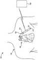
图1是示意图,示出了依据本公开的实施例的患者监测系统。1 is a schematic diagram illustrating a patient monitoring system in accordance with an embodiment of the present disclosure.
图2A是依据本公开的实施例的可植入医疗装置(IMD)的透视图。2A is a perspective view of an implantable medical device (IMD) in accordance with an embodiment of the present disclosure.
图2B和2C是依据本公开的实施例的在图2A中示出的IMD的局部分解透视图。2B and 2C are partially exploded perspective views of the IMD shown in FIG. 2A in accordance with embodiments of the present disclosure.
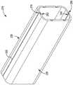
图3A是依据本公开的实施例的在图2A-2C中示出的IMD的核心组件壳体的透视图。3A is a perspective view of the core assembly housing of the IMD shown in FIGS. 2A-2C in accordance with an embodiment of the present disclosure.
图3B是依据本公开的实施例的在图3A中示出的核心组件壳体的分解前视图。3B is an exploded front view of the core assembly housing shown in FIG. 3A in accordance with an embodiment of the present disclosure.
图3C是依据本公开的实施例的在图3A和3B中示出的核心组件壳体的组装前视图。3C is an assembled front view of the core assembly housing shown in FIGS. 3A and 3B in accordance with an embodiment of the present disclosure.
图4是流程图,示出了依据本公开的实施例的组装IMD的说明性方法。4 is a flowchart showing an illustrative method of assembling an IMD in accordance with an embodiment of the present disclosure.
虽然所公开的主题适合于各种修改和替代形式,但是特定实施例已经通过示例方式在附图中被示出并且在以下被详细描述。然而,意图不是将所公开的主题限制于所描述的特定实施例。相反,所公开的主题旨在覆盖落入如所附权利要求书限定的所公开的主题的范围内的所有修改方案、等同方案和替代方案。While the disclosed subject matter is amenable to various modifications and alternative forms, specific embodiments have been shown by way of example in the drawings and are described in detail below. However, the intention is not to limit the disclosed subject matter to the particular embodiments described. On the contrary, the disclosed subject matter is intended to cover all modifications, equivalents, and alternatives falling within the scope of the disclosed subject matter as defined by the appended claims.
由于术语在本文中相对于测量范围而使用(比如直接上方所公开的那些),因此可以可互换地使用“大约”和“近似”来指代测量结果,其包括所陈述的测量结果并且其还包括任何测量结果,其合理地接近所陈述的测量结果,但是其可能合理地有少量不同,如相关领域的普通技术人员将会理解的,并且容易确定是可归因于测量误差、测量和/或制造器材校准上的差异、读取和/或设定测量上的人为错误、鉴于与其它部件相关联的测量上的差异而做出的用以最佳化性能和/或结构参数的调节、特定实施情形、不精确的调节和/或人员或机器对物体的操纵和/或类似原因。As terms are used herein in relation to measurement ranges (such as those disclosed immediately above), "about" and "approximately" may be used interchangeably to refer to measurements that include the stated measurements and which are Also included are any measurements that are reasonably close to the stated measurements, but which may reasonably differ in small amounts, as would be understood by those of ordinary skill in the relevant art, and readily determined to be attributable to measurement error, measurement and Variations in calibration of manufacturing equipment, human error in reading and/or setting measurements, adjustments made to optimize performance and/or structural parameters due to differences in measurements associated with other components , specific implementation situations, imprecise adjustment and/or manipulation of objects by humans or machines and/or similar reasons.
尽管术语“方框”可以在本文中被使用来暗示被说明性地采用的不同要素,但是该术语不应该解释为暗示对本文中公开的各个步骤的任何要求或者它们之中或之间的特定顺序,除非和例外的是明确地提及各个步骤的顺序时。Although the term "box" may be used herein to imply various elements that are illustratively employed, the term should not be interpreted as implying any requirement for the various steps disclosed herein or specificity among or between them order, unless and except when the order of the individual steps is explicitly mentioned.
具体实施方式Detailed ways
图1是系统100的示意图,所述系统包括可植入医疗装置(IMD)102,其植入患者的身体104内,并且构造为与接收装置106通信。在一些实施例中,IMD 102可以被皮下地植入患者的胸部或腹部中的囊袋或植入位置内,并且可以构造为监测(例如,感测和/或记录)与患者的心脏108相关联的生理参数。在一些实施例中,IMD 102可以是可植入心脏监测器(ICM)(例如,可植入诊断监测器(IDM)、可植入环记录器(ILR)等),其构造为记录生理参数,比如举例来说一个或更多个心脏激活信号、心脏声音、血压测量结果、氧饱和度和/或类似参数。在一些实施例中,IMD 102可以构造为监测生理参数,其可以包括表明患者的身体活动水平和/或代谢水平的一个或更多个信号,比如加速度信号。在一些实施例中,IMD 102可以构造为监测与一个或更多个其它器官、系统和/或类似物相关联的生理参数。IMD 102可以构造为以规则的间隔、连续地和/或响应于检测到的事件进行感测和/或记录。在一些实施例中,这种检测到的事件可以被IMD 102、另一IMD(未示出)、外部装置(例如,接收装置106)和/或类似物的一个或更多个传感器检测到。另外,IMD 102可以构造为检测各种各样的生理信号,其可以与各种诊断、治疗和/或监测实施方式相关联地使用。FIG. 1 is a schematic diagram of a
例如,IMD 102可以包括传感器或电路,其用于检测呼吸系统信号、心脏系统信号和/或与患者活动相关的信号。在一些实施例中,IMD 102可以构造为感测胸内阻抗,从其可以导出各种呼吸参数,包括例如呼吸潮气量和每分钟通气量。传感器和关联电路可以被包含在与IMD 102的连接中,以便检测一个或更多个身体移动或身体姿势和/或位置相关信号。例如,加速计和/或GPS装置可以被采用来检测患者活动、患者位置、身体取向和/或躯干位置。For example,
为了说明而不是限制的目的,依据本公开的可以用于记录生理参数的装置的各个实施例在本文中在可以被植入患者的胸部区域中的皮肤下的IMD的背景下被描述。然而,在一些实施例中,IMD 102可以包括任何类型的IMD、可植入系统的任何数量的不同部件、和/或具有壳体并且构造为植入患者的身体104中的类似物。例如,IMD 102可以包括控制装置、监测装置、起搏器、可植入心律转复除颤器(ICD)、心脏再同步治疗(CRT)装置和/或类似物,并且可以是本领域中公知的或以后开发的用于提供关于患者的身体和/或IMD 102的治疗和/或诊断数据的可植入医疗装置。在各个实施例中,IMD 102可以包括除颤和起搏/CRT能力(例如,CRT-D装置)。For purposes of illustration and not limitation, various embodiments of devices in accordance with the present disclosure that may be used to record physiological parameters are described herein in the context of a subcutaneous IMD that may be implanted in the thoracic region of a patient. However, in some embodiments,
如所示,IMD 102可以包括壳体110,其联接有两个电极112和114。根据一些实施例,IMD 102可以包括呈任何数量的各种类型的构造的任何数量的电极(和/或其它类型的传感器,比如举例来说温度计、气压计、压力传感器、光学传感器、运动传感器和/或类似物),并且壳体110可以包括任何数量的不同形状、尺寸和/或特征。在一些实施例中,IMD102可以构造为感测生理参数并且记录生理参数。例如,IMD 102可以构造为(例如,周期性地、连续地、在检测到事件时和/或类似情况下)启动,将指定量的数据(例如,生理参数)记录在内存中,并且将所记录的数据通信到接收装置106。在IDM的情况下,例如,IMD 102可以启动,记录心脏信号达一定时间段,停用,并且启动以将记录到的信号通信到接收装置106。As shown, the
在各个实施例中,接收装置106可以是例如编程器、控制器、患者监测系统和/或类似物。尽管在图1中示出为外部装置,但是接收装置106可以包括构造为与IMD 102通信的可植入装置,其可以例如是控制装置、另一监测装置、起搏器、可植入除颤器、心脏再同步治疗(CRT)装置和/或类似物,并且可以是本领域中公知的或以后开发的用于提供关于患者和/或IMD 102的治疗和/或诊断数据的可植入医疗装置。在各个实施例中,IMD 102可以是起搏器、可植入心律转复除颤器(ICD)装置、或心脏再同步治疗(CRT)装置。在各个实施例中,IMD102可以包括除颤和起搏/CRT能力(例如,CRT-D装置)。In various embodiments, the receiving
系统100根据本公开的实施例可以用于实施协调的患者测量和/或监测、诊断和/或治疗。系统100可以包括例如一个或更多个患者内医疗装置比如IMD 102,以及一个或更多个患者外医疗装置比如接收装置106。在一些实施例中,接收装置106可以构造为在患者外(即,不侵入性地植入患者的身体内)进行监测和/或诊断和/或治疗功能。接收装置106可以定位在患者身上,患者附近或患者体外的任何位置。
在一些实施例中,IMD 102和接收装置106可以透过无线链路通信。例如,IMD 102和接收装置106可以透过短程无线电链路比如蓝牙、IEEE 802.11和/或专有无线协议进行联接。通信链路可以促进IMD 102与接收装置106之间的单向和/或双向通信。数据和/或控制信号可以在IMD 102与接收装置106之间传输,以协调IMD 102和/或接收装置106的功能。在一些实施例中,患者数据可以周期性地或基于命令从IMD 102和接收装置106中的一个或更多个下载。医师和/或患者可以与IMD 102和接收装置106通信,例如用以获取患者数据或用以发起、终止或修改记录和/或治疗。In some embodiments,
图1中示出的说明性系统100并不旨在教示对于贯穿本公开所公开的主题的实施例的功能或用途的范围进行任何限制。说明性系统100也不应该被解释为具有与图1中示出的任何单个部件或部件组合相关的任何依存性或要求。例如,在一些实施例中,说明性系统100可以包括额外的部件。额外地,图1中示出的部件中的任一个或更多个可在一些实施例中与其中示出的其它部件(和/或未示出的部件)中的各个集成。任何数量的其它部件或部件组合都可与图1中示出的说明性系统100集成,它们全都被认为是在本公开的范围内。The
图2A是依据本公开的实施例的可植入医疗装置(IMD)200的透视图。IMD 200可以是或可以类似于图1中示出的IMD 102。如所示,IMD 200可以包括头盖202,其布置在核心组件204的第一端部220处或附近。电池组件206(其可以包括一个或更多个电池)布置在核心组件204的第二端部224附近。头盖202包括壳体202A,其封装内部区域202B。头盖202可以在其内部内容纳各种电路部件。当IMD 200被皮下地植入患者的胸部或腹部中的囊袋或植入位置中时,壳体202A可以接触患者的身体组织。头盖202的内部区域202B可以容纳电路部件(例如,电极208和天线210),其被支架组件212定位和支撑。如所示,除了电极208之外,IMD200还可以包括设置在电池组件206的端部处的电极214。在一些实施例中,电极214可以与电池组件206、电池组件206的壳体和/或类似物集成。为了允许感测患者内的生理参数,电极208可以定位为与头盖202的壳体202A的内表面平齐。在其它情况下,电极208可以通过支架组件212定位,以形成头盖202的壳体202A的外表面的一部分。2A is a perspective view of an implantable medical device (IMD) 200 in accordance with an embodiment of the present disclosure.
如图2B中所示,核心组件204包括封装在核心组件壳体218内的核心电路组件216。核心组件壳体218在第一端部220处联接到第一馈通组件222,并且在第二端部224处联接到第二馈通组件226。馈通组件222可以构造为提供用于连接的输出,其构造为将头盖202的电路部件(例如,电极208和天线210)连接到核心电路组件216。类似地,馈通组件226可以构造为提供用于连接的输出,其构造为将一个或更多个电池(例如,其是电池组件206的一部分)和/或电极214连接到核心电路组件216。As shown in FIG. 2B , the
如图2A中所示,核心组件壳体204包括第一部分228,其构造为沿着焊缝232联接到第二部分230。第一部分228和第二部分230可以通过激光焊接、缝焊接和/或类似方法联接在一起。在一些实施例中,不必使用单独的焊接环,因为第一和第二部分228和230中的至少一个的特征用作焊接环,保护核心电路组件216免受焊接能量(例如,热量、激光等)。As shown in FIG. 2A , the
例如,并且如下面进一步详细描述的,第一部分228可以包括一个或更多个焊接接头特征,其构造为定位邻近第二部分230上的一个或更多个相应的焊接接头特征,以准备用于焊接。在一些实施例中,例如,第一部分228和第二部分230可以包括连续弯曲壁(比如举例来说在起搏器或其它可植入脉冲发生器的实施方式中)、弯曲壁加直伸壁、若干弯曲壁、若干直伸壁和/或它们的任何数量的不同组合。第一部分228的每个壁(其构造为联接到第二部分230的相应壁)可以包括至少一个焊接接头特征,其构造为定位邻近第二部分230上的至少一个相应特征,并且在一些实施例中,反之亦然。For example, and as described in further detail below, the
每个焊接接头特征包括壁的薄化先导边缘(即构造为联接到壳体的另一部分的相应边缘的边缘)。也就是说,壁的边缘薄于壁的其它部段。以这种方式,当两个部分围绕核心电路组件定位以准备用于焊接时,两个部分之一的边缘可在另一部分的相应边缘上经过。以这种方式,封装在壳体内的容积可以得到最大化,并且在下边缘(即,更靠近核心电路组件的边缘)用作焊接环,保护核心电路组件在焊接程序期间免受所施加的能量(例如,热量、激光等)。在一些实施例中,焊接接头特征可以包括壁的铸造边缘、凸缘和/或类似物。Each weld joint feature includes a thinned leading edge of the wall (ie, an edge configured to couple to a corresponding edge of another portion of the housing). That is, the edges of the wall are thinner than the other sections of the wall. In this way, when the two parts are positioned around the core circuit assembly in preparation for soldering, the edge of one of the two parts can pass over the corresponding edge of the other part. In this way, the volume encapsulated within the housing can be maximized and the lower edge (ie, the edge closer to the core circuit assembly) acts as a solder ring, protecting the core circuit assembly from the energy applied during the soldering process ( For example, heat, laser, etc.). In some embodiments, weld joint features may include cast edges of walls, flanges, and/or the like.
如例如在图2B和2C中所示,核心组件壳体218的第一部分228包括侧壁234、下壁236和上壁238。下壁236和上壁238各自沿远离侧壁234的内表面234A的方向垂直地(或至少近似垂直地)延伸。如所示,下壁236通过弯曲角部240联接到侧壁234,并且上壁238通过弯曲角部242联接到侧壁234。在一些实施例中,弯曲角部240和242可以分别与下壁和上壁236和238、侧壁234和/或类似物集成。也就是说,例如,第一部分228可以是单件的金属,在压机或模具中形成。在一些实施例中,弯曲角部240和242可以是单独的部件。弯曲角部240和242各自可以设计为具有任何所需的曲率半径。例如,弯曲角部240和242各自可以构造为具有这样一种曲率半径,其提供封装在核心组件壳体218内的容积的所需量。As shown, for example, in FIGS. 2B and 2C , the
如例如在图2B和2C中所示,下壁236包括凸缘244,其相对于下壁236的内表面246凹入,并且其从第一部分228的第一端部248延伸到其第二端部250。凸缘244可以是下壁236的薄化部分。在一些实施例中,凸缘244可以焊接到下壁236。类似地,上壁238包括凸缘252,其相对于上壁238的内表面254凹入,并且其从第一部分228的第一端部248延伸到其第二端部250。凸缘252可以是上壁238的薄化部分。在一些实施例中,凸缘252可以焊接到上壁238。As shown, for example, in FIGS. 2B and 2C , the
如也例如在图2B和2C中所示,核心组件壳体218的第二部分230包括侧壁256、下壁258和上壁260。下壁258和上壁260各自沿远离侧壁256的内表面256A的方向垂直地(或至少近似垂直地)延伸。如所示,下壁258通过弯曲角部262联接到侧壁256,并且上壁260通过弯曲角部264联接到侧壁256。在一些实施例中,弯曲角部262和264可以分别与下壁和上壁258和260、侧壁256和/或类似物集成。也就是说,例如,第二部分230可以是单件的金属,在压机或模具中形成。在一些实施例中,弯曲角部262和264可以是单独的部件。弯曲角部262和264各自可以设计为具有任何所需的曲率半径,比如举例来说这样一种曲率半径,其相同于或者类似于弯曲角部240和242中的每个的曲率半径。例如,弯曲角部262和264各自可以构造为具有这样一种曲率半径,其提供封装在核心组件壳体218内的容积的所需量。As also shown, for example, in FIGS. 2B and 2C , the
如例如在图2B和2C中所示,下壁258包括凸缘266,其相对于下壁258的外表面268凹入,并且其从第二部分230的第一端部270延伸到其第二端部272。凸缘266可以是下壁258的薄化部分。在一些实施例中,凸缘266可以焊接到下壁258。类似地,上壁260包括凸缘274,其相对于上壁260的外表面276凹入,并且其从第二部分230的第一端部270延伸到其第二端部272。凸缘274可以是上壁260的薄化部分。在一些实施例中,凸缘274可以焊接到上壁260。As shown, for example, in FIGS. 2B and 2C , the
核心组件壳体218可以还包括槽口278,其被分别限定在第一部分228的第一和第二端部248和250中,并且从侧壁234的内表面234A延伸到外表面234B。类似地,核心组件壳体218可以还包括槽口280,其被分别限定在第二部分230的第一和第二端部270和272中,并且从侧壁256的内表面256A延伸到外表面256B。槽口278和280可以是渐进模具制造过程的人为产物,在所述渐进模具制造过程中核心组件壳体218的第一和第二部分228和230以连续条带生产并且在相继操作中成形。槽口278和280可以在第一和第二部分228和230从条带断脱时留下。在一些实施例中,条带可以构造为使得槽口小到足以在核心组件壳体218焊接到第一和第二馈通组件222和226时在焊池中被消耗。例如,在一些实施例中,槽口278和280可以延伸到部分228和230中达小于或等于大约0.003英寸。The
如图3A中所示,当第一部分228与第二部分230聚在一起时,凸缘244定位邻近凸缘266,并且凸缘252定位邻近凸缘274。部分228和230沿着凸缘244、266和252、274焊接在一起,不必插入单独的焊接环,因为凸缘266和凸缘274保护核心电路组件216,每个凸缘266和274用作集成的焊接环。As shown in FIG. 3A , when the
如图3B和3C中所示,凸缘244可以构造为使得核心组件壳体218的第一部分228的下壁236的内表面246的第一部段282与侧壁234的内表面234A是至少近似连续的。下壁236的内表面246的第二部段284可以相对于第一部段282以一定角度取向,并且可以从第一部段282的外侧边界向下延伸到内表面246的第三部段286。内表面246的第三部段286可以取向为平行于或至少近似平行于第一部段282。因此,第二部段284可以构造为在第一和第三部段282和286之间延伸的斜坡。As shown in FIGS. 3B and 3C , the
类似地,凸缘252可以构造为使得核心组件壳体218的第一部分228的上壁238的内表面254的第一部段288与侧壁234的内表面234A是至少近似连续的。上壁238的内表面254的第二部段290可以相对于第一部段288以一定角度取向,并且可以从第一部段288的外侧边界向上延伸到内表面254的第三部段292。内表面254的第三部段292可以取向为平行于或至少近似平行于第一部段288。因此,第二部段290可以构造为在第一和第三部段288和292之间延伸的斜坡。Similarly,
以类似的方式,凸缘266可以构造为使得核心组件壳体218的第二部分230的下壁258的外表面268的第一部段294与侧壁256的外表面256B是至少近似连续的。下壁258的外表面268的第二部段296可以相对于第一部段294以一定角度取向,并且可以从第一部段294向上延伸到外表面268的第三部段298。外表面268的第三部段298可以取向为平行于或至少近似平行于第一部段294。因此,第二部段296可以构造为在第一和第三部段294和298之间延伸的斜坡。In a similar manner,
额外地,凸缘274可以构造为使得核心组件壳体218的第二部分230的上壁260的外表面276的第一部段300与侧壁256的外表面256B是至少近似连续的。上壁260的外表面276的第二部段302可以相对于第一部段300以一定角度取向,并且可以从第一部段300向下延伸到外表面276的第三部段304。外表面376的第三部段304可以取向为平行于或至少近似平行于第一部段300。因此,第二部段302可以构造为在第一和第三部段300和304之间延伸的斜坡。Additionally, the
组装期间,如图3B和3C中所示,当第一部分228和第二部分230被聚在一起时,第一部分228的下壁236的先导边缘306可以构造为定位邻近第二部分230的下壁258的外表面268的第二部段296,并且第二部分230的下壁258的先导边缘308可以构造为定位邻近第一部分228的下壁236的内表面246的第二部段284,形成间隙322。类似地,第一部分228的上壁238的先导边缘310可以构造为定位邻近第二部分230的上壁260的外表面276的第二部段302,并且第二部分230的上壁260的先导边缘312可以构造为定位邻近第一部分228的上壁238的内表面254的第二部段290,形成间隙324。以这种方式,第三部段286、292、298和304可以是焊接表面,且第三部段298和304用作焊接环,从而保护核心电路组件216免受激光、热量、和/或其它焊接能量。During assembly, as shown in FIGS. 3B and 3C , when the
图2A-2C中示出的说明性IMD 200和图3A-3C中示出的说明性核心组件壳体218并不旨在教示对于贯穿本公开所公开的主题的实施例的功能或用途的范围进行任何限制。说明性IMD 200或说明性核心组件壳体218也不应该被解释为具有与图2A-2C或3A-3C中示出的任何单个部件、特征或部件或特征的组合相关的任何依存性或要求。例如,在一些实施例中,说明性IMD 200和/或说明性核心组件壳体218可以包括不同的和/或额外的部件和/或特征。任何数量的其它部件、特征或部件或特征的组合都可与图2A-2C中示出的说明性IMD200和/或图3A-3C中示出的说明性核心组件壳体218集成,它们全都被认为是在本公开的范围内。The
额外地,图2A-2C和3A-3C中示出中的部件和/或特征中的任一个或更多个可在一些实施例中与其中示出的其它部件和/或特征(和/或未示出的部件和/或特征)中的各个集成。例如,代替凸缘244、252、266和274,焊接接头特征可以是楔形边缘。也就是说,例如,第一部分228的下壁236的内表面的第二部段284和第三部段286可以是集成的,并且包括从第一部段282的外侧边界到先导边缘306在厚度上至少近似连续的减小。类似地,第一部分228的上壁238的内表面的第二部段290和第三部段292可以是集成的,并且包括从第一部段288的外侧边界到先导边缘310在厚度上至少近似连续的减小;第二部分230的下壁258的外表面268的第二部段296和第三部段298可以是集成的,并且包括从第一部段294的外侧边界到先导边缘308在厚度上至少近似连续的减小;并且第二部分230的上壁260的外表面276的第二部段302和第三部段304可以是集成的,并且包括从第一部段300的外侧边界到先导边缘312在厚度上至少近似连续的减小。Additionally, any one or more of the components and/or features shown in FIGS. 2A-2C and 3A-3C may in some embodiments be combined with other components and/or features (and/or components and/or features not shown). For example, instead of
额外地,在一些实施例中,核心组件壳体218可以仅在一个部分上包括一个或多个焊接接头特征。也就是说,例如,核心组件壳体218的实施例可以在第二部分230上只包括凸缘266(或楔形边缘)和凸缘274(或楔形边缘),在该情况下,凸缘266和274(或楔形边缘)可以包括分别比下壁和上壁258和260的内表面更向内(朝向核心电路组件)延伸的表面。Additionally, in some embodiments, the
另外,如本文中使用的,术语“侧壁”、“下壁”、“上壁”、“向上”和“向下”用于指代它们所涉及的特定特征,但是被表征在说明的背景中以为清楚起见,并且用以描述一些特征相对于其它特征的相对取向,并且并不旨在暗示IMD200的任何特定取向,或其特征的绝对(或优选)取向。也就是说,例如,即使IMD200围绕纵向轴线旋转使得侧壁234的外表面234B平行于水平面,侧壁234仍将被指代为“侧壁”,以利于本公开的目的。Additionally, as used herein, the terms "side wall," "lower wall," "upper wall," "upward," and "downward" are used to refer to the specific features to which they relate, but are characterized in the context of the description is used for clarity and to describe the relative orientation of some features relative to other features, and is not intended to imply any particular orientation of
具有构造为在不使用焊接环的情况下组装的核心组件壳体的IMD的实施例在以上被描述,并且包括设计为增强IMD的内部容积的构造。图4是流程图,示出了制造依据本公开的实施例的IMD的说明性方法400。IMD可以是例如图1中示出的IMD 102,图2A-2C中示出的IMD 200,和/或类似物。Embodiments of IMDs with core assembly housings configured to be assembled without the use of weld rings are described above and include configurations designed to enhance the interior volume of the IMD. FIG. 4 is a flowchart showing an
方法400的实施例包括提供核心电路组件(方框402),其可以包括获得和/或组装核心电路组件的一个或更多个部分,比如举例来说通过组装集成电路,联接电路到衬里,和/或类似步骤。方法400还可以包括提供头盖(方框404),其可以包括获得和/或组装头盖的一个或更多个部分,比如举例来说通过将电路部件(例如,电极和天线)布置在支架组件上并且将支架组件封装在头盖组件壳体内。方法400可以还包括提供电池组件(方框406)和提供馈通组件(方框408),其可以包括获得和/或组装电池组件和/或第一和第二馈通组件。Embodiments of
如图4中所示,方法400的实施例还包括联接馈通组件到核心电路组件(方框410),联接头盖到第一馈通组件(方框412),以及联接电池组件到第二馈通组件(方框414)。在一些实施例中,方法400包括建立核心组件壳体的具有焊接接头特征的第一和第二部分(方框416)。在一些实施例中,核心组件壳体部分可以是模制的、切割的和/或类似方法制成的,并且可以相同于或者类似于图2A-2C和3A-3C中示出的核心组件壳体部分228和230。如图4中所示,方法400的实施例还包括围绕核心电路组件定位核心组件壳体部分(方框418),以及沿着焊接接头特征将核心组件壳体部分焊接在一起(方框420)。As shown in FIG. 4, an embodiment of the
可以对所讨论的示例性实施例做出各种修改和增加,而不背离所公开的主题的范围。例如,虽然以上描述的实施例涉及特定特征,但是本公开的范围还包括具有不同特征组合的实施例和不包括所有已描述特征的实施例。相应地,所公开的主题的范围旨在包含如落在权利要求书的范围内的所有这种替代方案、修改方案和变型方案,及其全部等同方案。Various modifications and additions may be made to the exemplary embodiments discussed without departing from the scope of the disclosed subject matter. For example, although the embodiments described above relate to specific features, the scope of the disclosure also includes embodiments having different combinations of features and embodiments that do not include all of the described features. Accordingly, the scope of the disclosed subject matter is intended to encompass all such alternatives, modifications and variations as fall within the scope of the claims, and all equivalents thereof.
Claims (6)
Applications Claiming Priority (3)
| Application Number | Priority Date | Filing Date | Title |
|---|---|---|---|
| US201662324219P | 2016-04-18 | 2016-04-18 | |
| US62/324,219 | 2016-04-18 | ||
| PCT/US2017/027895WO2017184494A1 (en) | 2016-04-18 | 2017-04-17 | Medical device housing with weld joint features |
Publications (2)
| Publication Number | Publication Date |
|---|---|
| CN109069842A CN109069842A (en) | 2018-12-21 |
| CN109069842Btrue CN109069842B (en) | 2022-06-10 |
Family
ID=59253996
Family Applications (1)
| Application Number | Title | Priority Date | Filing Date |
|---|---|---|---|
| CN201780023937.2AActiveCN109069842B (en) | 2016-04-18 | 2017-04-17 | Medical device housing with weld joint features |
Country Status (4)
| Country | Link |
|---|---|
| US (1) | US10327344B2 (en) |
| EP (1) | EP3445446B1 (en) |
| CN (1) | CN109069842B (en) |
| WO (1) | WO2017184494A1 (en) |
Families Citing this family (9)
| Publication number | Priority date | Publication date | Assignee | Title |
|---|---|---|---|---|
| AU2016309014B2 (en) | 2015-08-20 | 2019-01-03 | Cardiac Pacemakers, Inc. | Header core fixation design for an IMD |
| JP2019513488A (en) | 2016-04-18 | 2019-05-30 | カーディアック ペースメイカーズ, インコーポレイテッド | Implantable medical device with core circuit support structure |
| WO2020000039A1 (en)* | 2018-06-29 | 2020-01-02 | Saluda Medical Pty Limited | Implantable neural stimulation device with two headers |
| EP3870278A1 (en) | 2018-10-28 | 2021-09-01 | Cardiac Pacemakers, Inc. | Implantable medical device having two electrodes in the header |
| US11400301B2 (en) | 2019-02-08 | 2022-08-02 | Cardiac Pacemakers, Inc. | Implantable medical device with reduced stress welded joint |
| EP3705158B1 (en)* | 2019-03-07 | 2024-08-07 | BIOTRONIK SE & Co. KG | Housing for an implantable medical device |
| US11446509B2 (en) | 2019-05-13 | 2022-09-20 | Cardiac Pacemakers, Inc. | Case driven design for implantable medical device |
| US20210186422A1 (en)* | 2019-12-20 | 2021-06-24 | Medtronic, Inc. | Implantable medical device with metal and polymer housing |
| WO2022076637A1 (en)* | 2020-10-09 | 2022-04-14 | Cardiac Pacemakers, Inc. | Imd enclosure formed using dielectric materials incorporating feedthru(s) |
Citations (1)
| Publication number | Priority date | Publication date | Assignee | Title |
|---|---|---|---|---|
| WO2002032503A1 (en)* | 2000-10-13 | 2002-04-25 | Medtronic, Inc. | Implantable medical device employing integral housing for a formable flat battery |
Family Cites Families (27)
| Publication number | Priority date | Publication date | Assignee | Title |
|---|---|---|---|---|
| JP2634284B2 (en) | 1990-03-26 | 1997-07-23 | 三菱電機株式会社 | Semiconductor device card frame, semiconductor device card using the same, and method of manufacturing the same |
| US5481434A (en) | 1993-10-04 | 1996-01-02 | Molex Incorporated | Memory card and frame for assembly therefor |
| DE69528029T2 (en) | 1994-06-16 | 2003-08-07 | Medtronic, Inc. | IMPLANTABLE CERAMIC APPLIANCE HOUSING |
| US5851221A (en) | 1996-12-05 | 1998-12-22 | Medtronic Inc. | Attachment apparatus and method for an implantable medical device |
| US5871514A (en) | 1997-08-01 | 1999-02-16 | Medtronic, Inc. | Attachment apparatus for an implantable medical device employing ultrasonic energy |
| DE19921928C2 (en)* | 1999-05-12 | 2002-11-14 | Bosch Gmbh Robert | Electric device |
| AUPQ056099A0 (en) | 1999-05-25 | 1999-06-17 | Silverbrook Research Pty Ltd | A method and apparatus (pprint01) |
| US6658296B1 (en) | 2001-06-19 | 2003-12-02 | Pacesetter, Inc. | Implantable cardioverter defibrillator having an articulated flexible circuit element and method of manufacturing |
| US6799072B2 (en) | 2002-04-25 | 2004-09-28 | Medtronic, Inc. | Electrically insulated component sub-assemblies of implantable medical devices |
| US7236834B2 (en) | 2003-12-19 | 2007-06-26 | Medtronic, Inc. | Electrical lead body including an in-line hermetic electronic package and implantable medical device using the same |
| US7288736B2 (en)* | 2004-10-19 | 2007-10-30 | Medtronic, Inc. | Connection between two components |
| US20060217778A1 (en) | 2005-03-22 | 2006-09-28 | James Strom | Methods of fabrication of shroud-based electrodes for monitoring cardiac activity |
| US7544220B2 (en) | 2005-03-31 | 2009-06-09 | Medtronic, Inc. | Welding methods and apparatus for batteries |
| US8065007B2 (en)* | 2005-05-16 | 2011-11-22 | Medtronic, Inc. | Method and apparatus for forming a hermetic enclosure seal in an implantable medical device |
| US20070016089A1 (en) | 2005-07-15 | 2007-01-18 | Fischell David R | Implantable device for vital signs monitoring |
| US7414855B1 (en) | 2005-10-05 | 2008-08-19 | Kyocera Wireless Corp. | Modular portable communication device with interchangeable outer housing assembly |
| US7668597B2 (en)* | 2006-03-31 | 2010-02-23 | Medtronic, Inc. | Feedthrough array for use in implantable medical devices |
| US8673194B2 (en) | 2007-05-04 | 2014-03-18 | Medtronic, Inc. | Method for forming a connector for an implantable medical device |
| KR100884717B1 (en)* | 2007-06-13 | 2009-02-19 | 안문상 | End of wiring mold connection |
| WO2009018172A2 (en) | 2007-07-27 | 2009-02-05 | Second Sight Medical Products | Implantable device for the brain |
| AU2009202778B2 (en)* | 2008-07-11 | 2014-05-08 | Commonwealth of Australia as represented by and acting through the Department of Climate Change, Energy, the Environment and Water | Improved baiting method and composition |
| US10449373B2 (en) | 2009-07-31 | 2019-10-22 | Medtronic, Inc. | Connector enclosure assemblies of medical devices including an angled lead passageway |
| US8093991B2 (en) | 2009-09-16 | 2012-01-10 | Greatbatch Ltd. | RFID detection and identification system for implantable medical devices |
| EP2667936B1 (en) | 2011-01-26 | 2017-08-23 | Medtronic, Inc. | Implantable medical devices and related connector enclosure assemblies utilizing conductors electrically coupled to feedthrough pins |
| US9345185B2 (en) | 2012-11-14 | 2016-05-17 | Medtronic, Inc. | Implantable medical device header |
| US9949376B2 (en) | 2013-12-06 | 2018-04-17 | Second Sight Medical Products, Inc. | Cortical implant system for brain stimulation and recording |
| DE102014111266A1 (en)* | 2014-08-07 | 2016-02-11 | Endress + Hauser Conducta Gesellschaft für Mess- und Regeltechnik mbH + Co. KG | Method for producing an inductive conductivity sensor and inductive conductivity sensor |
- 2017
- 2017-04-17CNCN201780023937.2Apatent/CN109069842B/enactiveActive
- 2017-04-17EPEP17734163.3Apatent/EP3445446B1/enactiveActive
- 2017-04-17WOPCT/US2017/027895patent/WO2017184494A1/ennot_activeCeased
- 2017-04-17USUS15/488,908patent/US10327344B2/enactiveActive
Patent Citations (1)
| Publication number | Priority date | Publication date | Assignee | Title |
|---|---|---|---|---|
| WO2002032503A1 (en)* | 2000-10-13 | 2002-04-25 | Medtronic, Inc. | Implantable medical device employing integral housing for a formable flat battery |
Non-Patent Citations (1)
| Title |
|---|
| 有源植入式医疗器械外壳封装工艺分析;黄德群;《中国医疗设备》;20080815;73-75* |
Also Published As
| Publication number | Publication date |
|---|---|
| EP3445446A1 (en) | 2019-02-27 |
| WO2017184494A1 (en) | 2017-10-26 |
| US10327344B2 (en) | 2019-06-18 |
| US20170303411A1 (en) | 2017-10-19 |
| EP3445446B1 (en) | 2024-09-11 |
| CN109069842A (en) | 2018-12-21 |
Similar Documents
| Publication | Publication Date | Title |
|---|---|---|
| CN109069842B (en) | Medical device housing with weld joint features | |
| US11706890B2 (en) | IMD having a core circuitry support structure | |
| US11678847B2 (en) | Power noise reduction for an integrated battery | |
| US11266843B2 (en) | Header core fixation design for an IMD | |
| US20200238091A1 (en) | Imd having anti-migration and device extraction features | |
| US20250229094A1 (en) | Imd enclosure formed using dielectric materials incorporating feedthru(s) | |
| US20230072666A1 (en) | Implantable medical device having two electrodes in the header | |
| CN115038494A (en) | Implantable medical device with biocompatible circuit board and embedded electrodes | |
| CN113260411B (en) | X-ray ID Tag Hydrogen Getter |
Legal Events
| Date | Code | Title | Description |
|---|---|---|---|
| PB01 | Publication | ||
| PB01 | Publication | ||
| SE01 | Entry into force of request for substantive examination | ||
| SE01 | Entry into force of request for substantive examination | ||
| GR01 | Patent grant | ||
| GR01 | Patent grant |