CN109048061B - End cap welding mechanism - Google Patents
End cap welding mechanismDownload PDFInfo
- Publication number
- CN109048061B CN109048061BCN201810963129.0ACN201810963129ACN109048061BCN 109048061 BCN109048061 BCN 109048061BCN 201810963129 ACN201810963129 ACN 201810963129ACN 109048061 BCN109048061 BCN 109048061B
- Authority
- CN
- China
- Prior art keywords
- end cap
- laser
- plate
- transplanting
- linear guide
- Prior art date
- Legal status (The legal status is an assumption and is not a legal conclusion. Google has not performed a legal analysis and makes no representation as to the accuracy of the status listed.)
- Active
Links
Images


Classifications
- B—PERFORMING OPERATIONS; TRANSPORTING
- B23—MACHINE TOOLS; METAL-WORKING NOT OTHERWISE PROVIDED FOR
- B23K—SOLDERING OR UNSOLDERING; WELDING; CLADDING OR PLATING BY SOLDERING OR WELDING; CUTTING BY APPLYING HEAT LOCALLY, e.g. FLAME CUTTING; WORKING BY LASER BEAM
- B23K26/00—Working by laser beam, e.g. welding, cutting or boring
- B23K26/20—Bonding
- B23K26/21—Bonding by welding
- B23K26/22—Spot welding
- B—PERFORMING OPERATIONS; TRANSPORTING
- B23—MACHINE TOOLS; METAL-WORKING NOT OTHERWISE PROVIDED FOR
- B23K—SOLDERING OR UNSOLDERING; WELDING; CLADDING OR PLATING BY SOLDERING OR WELDING; CUTTING BY APPLYING HEAT LOCALLY, e.g. FLAME CUTTING; WORKING BY LASER BEAM
- B23K26/00—Working by laser beam, e.g. welding, cutting or boring
- B23K26/08—Devices involving relative movement between laser beam and workpiece
- B23K26/0869—Devices involving movement of the laser head in at least one axial direction
- B—PERFORMING OPERATIONS; TRANSPORTING
- B23—MACHINE TOOLS; METAL-WORKING NOT OTHERWISE PROVIDED FOR
- B23K—SOLDERING OR UNSOLDERING; WELDING; CLADDING OR PLATING BY SOLDERING OR WELDING; CUTTING BY APPLYING HEAT LOCALLY, e.g. FLAME CUTTING; WORKING BY LASER BEAM
- B23K26/00—Working by laser beam, e.g. welding, cutting or boring
- B23K26/70—Auxiliary operations or equipment
- B23K26/702—Auxiliary equipment
- B—PERFORMING OPERATIONS; TRANSPORTING
- B23—MACHINE TOOLS; METAL-WORKING NOT OTHERWISE PROVIDED FOR
- B23K—SOLDERING OR UNSOLDERING; WELDING; CLADDING OR PLATING BY SOLDERING OR WELDING; CUTTING BY APPLYING HEAT LOCALLY, e.g. FLAME CUTTING; WORKING BY LASER BEAM
- B23K37/00—Auxiliary devices or processes, not specially adapted for a procedure covered by only one of the other main groups of this subclass
- B23K37/04—Auxiliary devices or processes, not specially adapted for a procedure covered by only one of the other main groups of this subclass for holding or positioning work
- B23K37/0426—Fixtures for other work
- B23K37/0435—Clamps
Landscapes
- Physics & Mathematics (AREA)
- Optics & Photonics (AREA)
- Engineering & Computer Science (AREA)
- Mechanical Engineering (AREA)
- Plasma & Fusion (AREA)
- Battery Electrode And Active Subsutance (AREA)
Abstract
Translated fromChinese
Description
Translated fromChinese技术领域technical field
本发明涉及端帽焊接领域,具体地,涉及一种端帽焊接机构。The invention relates to the field of end cap welding, in particular to an end cap welding mechanism.
背景技术Background technique
随着世界可再生能源的日益紧缺,锂离子电池作为清洁能源的一种受到越来越多的关注;目前锂离子电池广泛应用于手机、笔记本、后备电源、UPS、电动工具、数码产品等产品;当对锂离子电池进行充电时,电池的正极上有锂离子生成,生成的锂离子经过电解液运动到负极;而作为负极的碳呈层状结构,它有很多微孔,到达负极的锂离子就嵌入到碳层的微孔中,嵌入的锂离子越多,充电容量越高。With the increasing shortage of renewable energy in the world, lithium-ion batteries are attracting more and more attention as a kind of clean energy. At present, lithium-ion batteries are widely used in mobile phones, notebooks, backup power supplies, UPS, power tools, digital products and other products ; When the lithium ion battery is charged, lithium ions are generated on the positive electrode of the battery, and the generated lithium ions move to the negative electrode through the electrolyte; and the carbon as the negative electrode has a layered structure, which has many micropores, reaching the lithium ion of the negative electrode. The ions are inserted into the pores of the carbon layer, and the more lithium ions are inserted, the higher the charge capacity.
锂离子电池生产过程中,需要将电芯装入壳体内,随后将盖帽上的极片与电芯上的极耳焊接,焊接后将盖帽扣合在电池壳上,使得锂离子电池密封;目前大部分企业采用点焊机人工焊接极耳与盖帽,焊接精度低,影响锂离子电池性能的一致性;目前机械化、自动化生产已经逐渐成为发展趋势,并逐步代替传统的手工劳动,采用机械化、自动化生产有效保证了锂离子电池性能的一致性;现有点焊机的使用离不开操作者,难以嵌入锂离子电池生产自动线,锂离子电池生产效率低,并且点焊机焊接极耳与盖帽,焊接精度低,影响锂离子电池性能的一致性。In the production process of lithium-ion batteries, it is necessary to put the cells into the casing, and then weld the pole pieces on the cap to the tabs on the cells. After welding, the cap is fastened on the battery shell to seal the lithium-ion battery; currently Most companies use spot welding machines to manually weld the tabs and caps. The welding accuracy is low, which affects the consistency of lithium-ion battery performance. At present, mechanized and automated production has gradually become a development trend, and gradually replaces traditional manual labor. The production effectively ensures the consistency of the performance of lithium-ion batteries; the use of the existing spot welding machine is inseparable from the operator, it is difficult to embed the lithium-ion battery production automatic line, the production efficiency of lithium-ion batteries is low, and the spot welding machine welds the tabs and caps, welding The accuracy is low, which affects the consistency of lithium-ion battery performance.
发明内容SUMMARY OF THE INVENTION
本发明提供一种端帽焊接机构,以解决上述背景中现有点焊机焊接精度差和难以嵌入锂离子电池生产自动线的不足;一种端帽焊接机构包括台板;所述台板下方设置电动凸轮推动机构,所述台板上方设置壳体夹紧机构,所述壳体夹紧机构两侧分别设置端帽夹紧机构和激光焊接机构;所述电动凸轮推动机构设置第一传动杆和第二传动杆;所述电动凸轮推动机构上下滑动带动所述第一传动杆绕第一转轴摆动,带动所述端帽夹紧机构前后移动,实现贴合块按压极耳贴合端帽;所述电动凸轮推动机构上下滑动带动所述第二传动杆绕第一转轴摆动,带动所述壳体夹紧机构前后移动,实现夹具夹紧壳体;所述激光焊接机构通过水平移栽平台和激光器移栽机构调整激光器的位置,使得激光器的激光光点与极耳和端帽保持一致,保证极耳和端帽的焊接精度,采用激光器焊接大大提高焊接效率;同时端帽焊接机构可阵列排布在锂离子电池生产自动线上,实现多工位焊接。The present invention provides an end cap welding mechanism to solve the problems of poor welding accuracy of existing spot welding machines and difficulty in embedding lithium ion battery production automatic lines in the above-mentioned background; an end cap welding mechanism includes a platen; an electric motor is arranged under the platen. A cam push mechanism, a casing clamping mechanism is arranged above the platen, and an end cap clamping mechanism and a laser welding mechanism are respectively provided on both sides of the casing clamping mechanism; the electric cam pushing mechanism is provided with a first transmission rod and a second Two transmission rods; the electric cam pushing mechanism slides up and down to drive the first transmission rod to swing around the first rotating shaft, and drives the end cap clamping mechanism to move back and forth, so that the fitting block presses the pole ear to fit the end cap; the The electric cam push mechanism slides up and down to drive the second transmission rod to swing around the first rotation axis, and drives the shell clamping mechanism to move back and forth to realize the clamp clamping the shell; the laser welding mechanism is moved by the horizontal transplanting platform and the laser. A mechanism adjusts the position of the laser so that the laser spot of the laser is consistent with the tab and end cap, ensuring the welding accuracy of the tab and end cap. Laser welding greatly improves the welding efficiency; at the same time, the end cap welding mechanism can be arranged in an array on Lithium-ion battery production automatic line, realize multi-station welding.
本发明的技术方案如下:The technical scheme of the present invention is as follows:
一种端帽焊接机构,包括台板,所述台板下方设置电动凸轮推动机构,所述台板上方设置壳体夹紧机构,所述壳体夹紧机构两侧分别设置端帽夹紧机构和激光焊接机构;所述电动凸轮推动机构设置第一传动杆和第二传动杆;所述电动凸轮推动机构上下滑动带动所述第一传动杆绕第一转轴摆动,带动所述端帽夹紧机构前后移动,实现贴合块按压极耳贴合端帽;所述电动凸轮推动机构上下滑动带动所述第二传动杆绕第一转轴摆动,带动所述壳体夹紧机构前后移动,实现夹具夹紧壳体;所述激光焊接机构通过水平移栽平台和激光器移栽机构调整激光器的位置,使得激光器的激光光点与极耳和端帽保持一致,保证极耳和端帽的焊接精度,采用激光器焊接大大提高焊接效率;同时端帽焊接机构可阵列排布在锂离子电池生产自动线上,实现多工位焊接。An end cap welding mechanism, comprising a platen, an electric cam pushing mechanism is arranged below the platen, a shell clamping mechanism is arranged above the platen, and end cap clamping mechanisms are respectively arranged on both sides of the shell clamping mechanism and a laser welding mechanism; the electric cam push mechanism is provided with a first transmission rod and a second transmission rod; the electric cam push mechanism slides up and down to drive the first transmission rod to swing around the first rotating shaft, driving the end cap to clamp The mechanism moves back and forth to make the fitting block press the pole lug to fit the end cap; the electric cam pushing mechanism slides up and down to drive the second transmission rod to swing around the first shaft, and drives the housing clamping mechanism to move back and forth to realize the fixture Clamp the shell; the laser welding mechanism adjusts the position of the laser through the horizontal transplanting platform and the laser transplanting mechanism, so that the laser spot of the laser is consistent with the pole lug and the end cap, and the welding accuracy of the pole lug and the end cap is ensured. The use of laser welding greatly improves the welding efficiency; at the same time, the end cap welding mechanism can be arranged in an array on the lithium-ion battery production automatic line to realize multi-station welding.
进一步,所述电动凸轮推动机构包括所述电动凸轮推动机构包括驱动电机机构、凸轮、滚轮、第一摆臂、第二转轴、第一随动柱、第二摆臂、第三转轴和第二随动柱;所述凸轮中心孔与所述驱动电机机构输出轴键连接,所述滚轮与所述凸轮外侧接触;所述第一摆臂两端分别与所述滚轮和所述第一随动柱一端连接,且绕所述第二转轴摆动;所述第二摆臂两端分别与所述第一随动柱另一端和所述第二随动柱一端连接,且绕所述第三转轴摆动;通过所述驱动电机机构输出轴旋转带动所述凸轮旋转,所述滚轮沿着所述凸轮外侧轮廓滚动,实现最高点和最低点的渐变,并依次带动所述第一摆臂摆动、所述第一随动柱上下滑动、所述第二摆臂摆动和所述第二随动柱上下滑动,提高所述第二随动柱上下滑动的效率,从而提高贴合块按压极耳贴合端帽和夹具夹紧壳体的效率。Further, the electric cam push mechanism includes a drive motor mechanism, a cam, a roller, a first swing arm, a second shaft, a first follower column, a second swing arm, a third shaft and a second a follower column; the center hole of the cam is keyed to the output shaft of the drive motor mechanism, and the roller is in contact with the outer side of the cam; the two ends of the first swing arm are respectively connected to the roller and the first follower One end of the column is connected and swings around the second rotation axis; both ends of the second swing arm are respectively connected with the other end of the first follower column and one end of the second follower column, and rotate around the third axis Swing; the rotation of the output shaft of the driving motor mechanism drives the cam to rotate, and the roller rolls along the outer contour of the cam to realize the gradual change of the highest point and the lowest point, and sequentially drives the first swing arm to swing, all the The first follower column slides up and down, the second swing arm swings, and the second follower column slides up and down, so as to improve the efficiency of the second follower column to slide up and down, thereby improving the fit of the pressing tab of the fitting block. Efficiency of end caps and clamps to clamp the housing.
进一步,所述壳体夹紧机构包括设置在所述第一立架上方的第二直线导轨、设置在所述第二直线导轨上方的平板和设置在所述平板一侧的夹具;所述平板一侧设有卡合所述第二传动杆的第二卡合槽;所述夹具设有固定壳体的夹紧槽;通过所述电动凸轮推动机构旋转带动所述第二传动杆绕第一转轴摆动,带动所述夹具沿所述第二直线导轨方向移动,使得所述夹具的夹紧槽夹紧壳体。Further, the shell clamping mechanism includes a second linear guide rail arranged above the first vertical frame, a flat plate arranged above the second linear guide rail, and a clamp arranged on one side of the flat plate; the flat plate One side is provided with a second engaging groove for engaging the second transmission rod; the clamp is provided with a clamping groove for fixing the casing; the second transmission rod is driven to rotate around the first transmission rod by the electric cam pushing mechanism The rotating shaft swings to drive the clamp to move along the direction of the second linear guide rail, so that the clamping groove of the clamp clamps the housing.
进一步,所述端帽夹紧机构包括第一立架、第一直线导轨、气缸移栽机构、贴合机构和废气回收管;所述气缸移栽机构和所述贴合机构均设置在所述第一直线导轨一侧,第一立架设置在所述第一直线导轨另一侧;所述第一直线导轨设置三块滑块,其中一个滑块与所述气缸移栽机构固定,两个滑块与所述贴合机构固定。Further, the end cap clamping mechanism includes a first stand, a first linear guide rail, a cylinder transplanting mechanism, a fitting mechanism and an exhaust gas recovery pipe; the cylinder transplanting mechanism and the fitting mechanism are both arranged at the On one side of the first linear guide rail, the first stand is arranged on the other side of the first linear guide rail; the first linear guide rail is provided with three sliding blocks, one of which is connected to the cylinder transplanting mechanism Fixed, the two sliders are fixed with the fitting mechanism.
进一步,所述气缸移栽机构包括设置在所述第一直线导轨上方的固定架和设置在所述固定架一侧的气缸;所述固定架设有卡合所述第一传动杆的第一卡合槽;所述贴合机构包括设置在所述第一直线导轨上的座板、设置在所述座板一侧的第一L型板和设置在所述座板另一侧的第二L型板;所述第一L型板与所述气缸输出轴固定连接;所述第二L型板一侧设置垫板,所述垫板一侧设置贴合块;所述贴合块按压极耳贴合端帽;通过所述气缸输出轴伸出带动所述第一L型板沿所述第一直线导轨方向移动,并且实现所述贴合块气动按压极耳贴合端帽,保证极耳与端帽无间隙贴合,方便极耳与端帽的焊接。Further, the cylinder transplanting mechanism includes a fixing frame arranged above the first linear guide rail and a cylinder arranged on one side of the fixing frame; the fixing frame is provided with a first transmission rod that engages with the first transmission rod. an engaging groove; the fitting mechanism includes a seat plate arranged on the first linear guide rail, a first L-shaped plate arranged on one side of the seat plate, and a first L-shaped plate arranged on the other side of the seat plate Two L-shaped plates; the first L-shaped plate is fixedly connected with the cylinder output shaft; a backing plate is arranged on one side of the second L-shaped plate, and a bonding block is arranged on one side of the backing plate; the bonding block Press the tab to fit the end cap; the first L-shaped plate is driven to move along the direction of the first linear guide by the extension of the cylinder output shaft, and the fitting block can pneumatically press the tab to fit the end cap. , to ensure that the tabs and the end caps fit without gaps, which is convenient for the welding of the tabs and the end caps.
进一步,所述废气回收管设置在所述第二L型板一侧;所述废气回收管一端贴合所述垫板一侧;所述废气回收管回收所述激光焊接机构产生的废气。Further, the exhaust gas recovery pipe is arranged on one side of the second L-shaped plate; one end of the exhaust gas recovery pipe is attached to one side of the backing plate; the exhaust gas recovery pipe recovers the exhaust gas generated by the laser welding mechanism.
进一步,所述激光焊接机构包括第三立架、水平移栽平台、激光器移栽机构和激光器;所述第三立架设置在所述水平移栽平台一侧;所述激光器移栽机构设置在所述水平移栽平台另一侧,所述激光器设置在所述激光器移栽机构一侧;所述激光焊接机构通过水平移栽平台和激光器移栽机构调整激光器的位置,使得激光器的激光光点与极耳和端帽保持一致,保证极耳和端帽的焊接精度。Further, the laser welding mechanism includes a third stand, a horizontal transplanting platform, a laser transplanting mechanism and a laser; the third stand is arranged on one side of the horizontal transplanting platform; the laser transplanting mechanism is arranged on the side of the horizontal transplanting platform. On the other side of the horizontal transplanting platform, the laser is arranged on one side of the laser transplanting mechanism; the laser welding mechanism adjusts the position of the laser through the horizontal transplanting platform and the laser transplanting mechanism, so that the laser spot of the laser is Consistent with the tabs and end caps to ensure the welding accuracy of the tabs and end caps.
进一步,所述水平移栽平台包括伺服电机、与所述伺服电机输出轴连接的同步带机构、与所述同步带机构一端连接的丝杆传动机构、设置在所述丝杆传动机构两侧的两个第三直线导轨和设置在所述丝杆传动机构上方的载板;通过所述伺服电机输出轴旋转,带动所述同步带机构和所述丝杆传动机构旋转,使得所述载板沿所述第三直线导轨直线移动。Further, the horizontal transplanting platform includes a servo motor, a timing belt mechanism connected with the output shaft of the servo motor, a screw drive mechanism connected with one end of the timing belt mechanism, and a screw drive mechanism arranged on both sides of the screw drive mechanism. Two third linear guide rails and a carrier plate arranged above the screw transmission mechanism; the rotation of the output shaft of the servo motor drives the synchronous belt mechanism and the screw transmission mechanism to rotate, so that the carrier plate rotates along the The third linear guide rail moves linearly.
进一步,所述激光器移栽机构包括设置在所述载板上的立板、设置在所述立板一侧的滑台、设置在所述滑台一侧的固定板;所述固定板通过螺丝固定所述激光器;通过所述滑台微调所述激光器的位置,使得激光器的激光光点与极耳和端帽保持一致,保证极耳和端帽的焊接精度。Further, the laser transplanting mechanism includes a vertical plate arranged on the carrier plate, a sliding table arranged on one side of the vertical plate, and a fixing plate arranged on one side of the sliding table; the fixing plate is provided by screws The laser is fixed; the position of the laser is fine-tuned by the sliding table, so that the laser spot of the laser is consistent with the tab and the end cap, and the welding accuracy of the tab and the end cap is ensured.
与现有技术相比,本发明端帽焊接机构具有以下有益效果:Compared with the prior art, the end cap welding mechanism of the present invention has the following beneficial effects:
1、所述电动凸轮推动机构上下滑动带动所述第一传动杆绕第一转轴摆动,带动所述端帽夹紧机构前后移动,实现贴合块按压极耳贴合端帽。1. The electric cam pushing mechanism slides up and down to drive the first transmission rod to swing around the first rotating shaft, and drives the end cap clamping mechanism to move back and forth, so that the fitting block presses the pole lug to fit the end cap.
2、所述电动凸轮推动机构上下滑动带动所述第二传动杆绕第一转轴摆动,带动所述壳体夹紧机构前后移动,实现夹具夹紧壳体。2. The electric cam pushing mechanism slides up and down to drive the second transmission rod to swing around the first rotating shaft, and drives the casing clamping mechanism to move back and forth, so as to realize the clamping of the casing by the clamp.
3、所述激光焊接机构通过水平移栽平台和激光器移栽机构调整激光器的位置,使得激光器的激光光点与极耳和端帽保持一致,保证极耳和端帽的焊接精度,采用激光器焊接大大提高焊接效率。3. The laser welding mechanism adjusts the position of the laser through the horizontal transplanting platform and the laser transplanting mechanism, so that the laser spot of the laser is consistent with the pole ear and the end cap, and the welding accuracy of the pole ear and the end cap is ensured. Greatly improve welding efficiency.
4、采用电动凸轮推动机构驱动提高贴合块按压极耳贴合端帽和夹具夹紧壳体的效率,从而提高端帽焊接机构的工作效率。4. The electric cam driving mechanism is adopted to improve the efficiency of the fitting block pressing the tabs to fit the end cap and the clamp to clamp the shell, thereby improving the working efficiency of the end cap welding mechanism.
5、所述端帽焊接机构整体占用空间小,方便嵌入锂离子电池生产自动线上,并且所述端帽焊接机构可实现多工位焊接极耳和端帽。5. The end cap welding mechanism occupies a small space as a whole, which is convenient for embedding into an automatic production line of lithium ion batteries, and the end cap welding mechanism can realize multi-position welding of the tabs and end caps.
附图说明:Description of drawings:
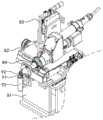
图1是本发明端帽焊接机构的立体图;1 is a perspective view of an end cap welding mechanism of the present invention;
图2是沿图1中A向的局部放大图;Fig. 2 is a partial enlarged view along the direction A in Fig. 1;
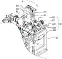
图3是本发明端帽焊接机构的俯视图;Fig. 3 is the top view of the end cap welding mechanism of the present invention;
图4是本发明端帽焊接机构的壳体夹紧机构的动作示意图;Fig. 4 is the action schematic diagram of the shell clamping mechanism of the end cap welding mechanism of the present invention;
图5是本发明端帽焊接机构的端帽夹紧机构的动作示意图;Fig. 5 is the action schematic diagram of the end cap clamping mechanism of the end cap welding mechanism of the present invention;
图6是本发明端帽焊接机构的端帽夹紧机构的结构示意图;6 is a schematic structural diagram of the end cap clamping mechanism of the end cap welding mechanism of the present invention;
图7是本发明端帽焊接机构的激光焊接机构的立体图;7 is a perspective view of the laser welding mechanism of the end cap welding mechanism of the present invention;
图8是本发明端帽焊接机构的激光焊接机构的结构示意图。FIG. 8 is a schematic structural diagram of the laser welding mechanism of the end cap welding mechanism of the present invention.
台板1、电动凸轮推动机构2、端帽夹紧机构3、第一传动杆4、第二传动杆5、第一转轴6、壳体夹紧机构7、激光焊接机构8、极耳91、端帽92、壳体93、驱动电机机构21、凸轮22、滚轮23、第一摆臂24、第二转轴25、第一随动柱26、第二摆臂27、第三转轴28、第二随动柱29、第一立架31、第一直线导轨32、滑块321、气缸移栽机构33、固定架331、第一卡合槽3311、气缸332、贴合机构34、座板341、第一L型板342、第二L型板343、垫板344、贴合块345、废气回收管35、第二直线导轨71、平板72、第二卡合槽721、夹具73、夹紧槽731、第三立架81、水平移栽平台82、激光器移栽机构83、激光器84、伺服电机821、同步带机构822、丝杆传动机构823、第三直线导轨824、载板825、立板831、滑台832、固定板833。Platen 1, electric
具体实施方式Detailed ways
下面将结合本发明实施例中的附图,对本发明实施例中的技术方案进行清楚、完整地描述,显然,所描述的实施例仅仅是本发明一部分实施例,而不是全部的实施例。基于本发明中的实施例,本领域普通技术用户员在没有做出创造性劳动前提下所获得的所有其他实施例,都属于本发明保护的范围。The technical solutions in the embodiments of the present invention will be clearly and completely described below with reference to the accompanying drawings in the embodiments of the present invention. Obviously, the described embodiments are only a part of the embodiments of the present invention, but not all of the embodiments. Based on the embodiments of the present invention, all other embodiments obtained by users of ordinary skill in the art without creative efforts shall fall within the protection scope of the present invention.
参照图1-3,一种端帽焊接机构,包括台板1;所述台板1下方设置电动凸轮推动机构2,所述台板1上方设置壳体夹紧机构7,所述壳体夹紧机构7两侧分别设置端帽夹紧机构3和激光焊接机构8;所述电动凸轮推动机构2设置第一传动杆4和第二传动杆5;所述电动凸轮推动机构2上下滑动带动所述第一传动杆4绕第一转轴6摆动,带动所述端帽夹紧机构3前后移动,实现贴合块345按压极耳91贴合端帽92;所述电动凸轮推动机构2上下滑动带动所述第二传动杆5绕第一转轴6摆动,带动所述壳体夹紧机构7前后移动,实现夹具73夹紧壳体93;所述激光焊接机构8通过水平移栽平台82和激光器移栽机构83调整激光器84的位置,使得激光器84的激光光点与极耳91和端帽92保持一致,保证极耳91和端帽92的焊接精度,采用激光器84焊接大大提高焊接效率;同时端帽焊接机构可阵列排布在锂离子电池生产自动线上,实现多工位焊接。1-3, an end cap welding mechanism includes a platen 1; an electric
参照图2、4和6,所述电动凸轮推动机构2包括驱动电机机构21、凸轮22、滚轮23、第一摆臂24、第二转轴25、第一随动柱26、第二摆臂27、第三转轴28和第二随动柱29;所述凸轮22中心孔与所述驱动电机机构21输出轴键连接,通过所述驱动电机机构21输出轴旋转带动所述凸轮22旋转;所述滚轮23与所述凸轮22外侧接触,所述滚轮23随所述凸轮22的旋转沿外侧轮廓滚动,保持所述滚轮23与所述凸轮22的外侧相切;所述第一摆臂24两端分别与所述滚轮23和所述第一随动柱26一端连接,且绕所述第二转轴25摆动;所述第二摆臂27两端分别与所述第一随动柱26另一端和所述第二随动柱29一端连接,且绕所述第三转轴28摆动;通过所述驱动电机机构21输出轴旋转带动所述凸轮22旋转,所述滚轮23沿着所述凸轮22外侧轮廓滚动,实现最高点和最低点的渐变,并依次带动所述第一摆臂24摆动、所述第一随动柱25上下滑动、所述第二摆臂26摆动和所述第二随动柱27上下滑动,提高所述第二随动柱27上下滑动的效率,从而提高所述贴合块345按压所述极耳91贴合所述端帽92和所述夹具73夹紧所述壳体93的效率。2 , 4 and 6 , the electric
参照图2和4,所述电动凸轮推动机构2的所述第二随动柱29通过所述滚轮23沿着所述凸轮22外侧轮廓滚动而上下滑动,所述第二随动柱29的上下滑动带动所述第一传动杆4绕第一转轴6摆动,实现贴合块345按压极耳8贴合端帽9,并且提高极耳8贴合端帽9的效率;同时所述壳体夹紧机构7前后移动与所述第二随动柱29上下滑动同步,从而带动所述夹具73沿所述第二直线导轨71方向前后移动,实现夹具73夹紧壳体93。2 and 4 , the
所述壳体夹紧机构7包括设置在所述第一立架31上方的第二直线导轨71、设置在所述第二直线导轨71上方的平板72和设置在所述平板72一侧的夹具73;所述平板72一侧设有卡合所述第二传动杆5的第二卡合槽721;所述夹具73设有固定壳体的夹紧槽731;所述电动凸轮推动机构2的所述第二随动柱29通过所述滚轮23沿着所述凸轮22外侧轮廓滚动而上下滑动,所述第二随动柱29的上下滑动带动所述第二传动杆5绕第一转轴6摆动,所述平板72沿第二直线导轨71方向前后移动,使得所述夹具73的夹紧槽731夹紧壳体93;通过所述电动凸轮推动机构2驱动提高所述壳体夹紧机构7的工作效率。The
参照图2、5和6,所述端帽夹紧机构3包括第一立架31、第一直线导轨32、气缸移栽机构33、贴合机构34和废气回收管35;所述气缸移栽机构33和所述贴合机构34均设置在所述第一直线导轨32一侧,第一立架31设置在所述第一直线导轨32另一侧;通过所述电动凸轮推动机构2的所述第二随动柱29上下滑动带动所述气缸移栽机构33前后移动,而所述气缸移栽机构33通过气缸332输出轴伸缩实现所述贴合机构34沿所述第一直线导轨32方向前后移动,实现所述贴合块345气动按压所述极耳91贴合所述端帽92,保证所述极耳91与所述端帽92无间隙贴合,方便所述极耳91与所述端帽92的焊接。2, 5 and 6, the end cap clamping mechanism 3 includes a
所述第一直线导轨32设置三块滑块321,其中一个滑块321与所述气缸移栽机构33固定,两个滑块321与所述贴合机构34固定;所述气缸移栽机构33包括设置在所述第一直线导轨32上方的固定架331和设置在所述固定架331一侧的气缸332;所述固定架331设有卡合所述第一传动杆4的第一卡合槽3311;所述第一传动杆4绕所述第一转轴6摆动,带动所述固定架331沿所述第一直线导轨32方向前后移动,从而带动所述气缸332前后移动。The first
所述贴合机构34包括设置在所述第一直线导轨32上的座板341、设置在所述座板341一侧的第一L型板342和设置在所述座板341另一侧的第二L型板343;所述第一L型板342与所述气缸332输出轴固定连接;所述第二L型板343一侧设置垫板344,所述垫板344一侧设置贴合块345;通过所述气缸332输出轴伸缩依次带动所述第一L型板342、所述座板341和所述第二L型板343沿所述第一直线导轨32方向前后移动,从而实现所述贴合块345气动按压极耳91贴合端帽92,保证所述极耳91与所述端帽92无间隙贴合,方便所述极耳91与所述端帽92的焊接。The
所述废气回收管35设置在所述第二L型板343一侧;所述废气回收管35一端贴合所述垫板344一侧;所述废气回收管35与净化器连接,通过净化器负压回收所述激光焊接机构8产生的废气。The exhaust
参照图2、7和8,所述激光焊接机构8包括第三立架81、水平移栽平台82、激光器移栽机构83和激光器84;所述第三立架81设置在所述水平移栽平台82一侧;所述激光器移栽机构83设置在所述水平移栽平台82另一侧,所述激光器84设置在所述激光器移栽机构83一侧;所述激光焊接机构8通过所述水平移栽平台82和所述激光器移栽机构83调整所述激光器84的位置,使得所述激光器84的激光光点与所述极耳91和所述端帽92保持一致,保证所述极耳91和所述端帽92的焊接精度,采用所述激光器84焊接大大提高焊接效率;同时端帽焊接机构可阵列排布在锂离子电池生产自动线上,实现多工位焊接;2, 7 and 8, the
所述水平移栽平台82包括伺服电机821、与所述伺服电机821输出轴连接的同步带机构822、与所述同步带机构822一端连接的丝杆传动机构823、设置在所述丝杆传动机构823两侧的两个第三直线导轨824和设置在所述丝杆传动机构823上方的载板825;通过所述伺服电机821输出轴旋转,带动所述同步带机构822传动并实现所述丝杆传动机构823所述沿两个所述第三直线导轨824方向直线移栽,实现所述激光器84的左右位置调整。The
所述激光器移栽机构83包括设置在所述载板825上的立板831、设置在所述立板831一侧的滑台832、设置在所述滑台832一侧的固定板833;所述固定板833通过螺丝固定所述激光器84;通过所述滑台832微调所述激光器84的上下位置;所述激光焊接机构8通过所述水平移栽平台82和所述激光器移栽机构83调整所述激光器84的位置,使得所述激光器84的激光光点与所述极耳91和所述端帽92保持一致,保证所述极耳91和所述端帽92的焊接精度,采用所述激光器84焊接大大提高焊接效率;同时端帽焊接机构可阵列排布在锂离子电池生产自动线上,实现多工位焊接。The
本发明不局限于上述具体的实施方式,本领域的普通技术用户员从上述构思出发,不经过创造性的劳动,所做出的种种变换,均落在本发明的保护范围。The present invention is not limited to the above-mentioned specific embodiments, and various transformations made by users of ordinary skill in the art from the above-mentioned concept without creative work all fall within the protection scope of the present invention.
Claims (8)
Translated fromChinesePriority Applications (1)
| Application Number | Priority Date | Filing Date | Title |
|---|---|---|---|
| CN201810963129.0ACN109048061B (en) | 2018-08-22 | 2018-08-22 | End cap welding mechanism |
Applications Claiming Priority (1)
| Application Number | Priority Date | Filing Date | Title |
|---|---|---|---|
| CN201810963129.0ACN109048061B (en) | 2018-08-22 | 2018-08-22 | End cap welding mechanism |
Publications (2)
| Publication Number | Publication Date |
|---|---|
| CN109048061A CN109048061A (en) | 2018-12-21 |
| CN109048061Btrue CN109048061B (en) | 2020-07-24 |
Family
ID=64755798
Family Applications (1)
| Application Number | Title | Priority Date | Filing Date |
|---|---|---|---|
| CN201810963129.0AActiveCN109048061B (en) | 2018-08-22 | 2018-08-22 | End cap welding mechanism |
Country Status (1)
| Country | Link |
|---|---|
| CN (1) | CN109048061B (en) |
Families Citing this family (2)
| Publication number | Priority date | Publication date | Assignee | Title |
|---|---|---|---|---|
| KR102311428B1 (en)* | 2019-10-24 | 2021-10-12 | 삼성에스디아이 주식회사 | Push device for laser welding |
| CN120206007B (en)* | 2025-04-24 | 2025-08-22 | 泊头市通华模具有限公司 | A laser spot welding machine for mold processing |
Citations (8)
| Publication number | Priority date | Publication date | Assignee | Title |
|---|---|---|---|---|
| CN201471081U (en)* | 2009-08-14 | 2010-05-19 | 武汉逸飞激光设备有限公司 | Fully automatic laser welding device for battery tabs and caps |
| CN202240342U (en)* | 2011-08-18 | 2012-05-30 | 合肥国轩高科动力能源有限公司 | Aluminum shell cylindrical battery seal welding clamp |
| US8447402B1 (en)* | 2006-03-31 | 2013-05-21 | Alfred E. Mann Foundation For Scientific Research | Zirconia to platinum assembly using a titanium connector |
| CN205115772U (en)* | 2015-10-27 | 2016-03-30 | 江苏润源控股集团有限公司 | A swing mechanism that is used for tricot machine sley bar sideslip subassembly |
| CN106425079A (en)* | 2016-11-17 | 2017-02-22 | 惠州市龙海科技有限公司 | Capping machine electrode lug positioning and welding mechanism |
| CN206169635U (en)* | 2016-10-31 | 2017-05-17 | 深圳市沃特玛电池有限公司 | Battery block welding set |
| CN206464702U (en)* | 2017-01-23 | 2017-09-05 | 安徽天时新能源科技有限公司 | A kind of battery cap welding device |
| CN206883072U (en)* | 2017-05-18 | 2018-01-16 | 东莞市沃泰通新能源有限公司 | A battery tab welding structure |
- 2018
- 2018-08-22CNCN201810963129.0Apatent/CN109048061B/enactiveActive
Patent Citations (8)
| Publication number | Priority date | Publication date | Assignee | Title |
|---|---|---|---|---|
| US8447402B1 (en)* | 2006-03-31 | 2013-05-21 | Alfred E. Mann Foundation For Scientific Research | Zirconia to platinum assembly using a titanium connector |
| CN201471081U (en)* | 2009-08-14 | 2010-05-19 | 武汉逸飞激光设备有限公司 | Fully automatic laser welding device for battery tabs and caps |
| CN202240342U (en)* | 2011-08-18 | 2012-05-30 | 合肥国轩高科动力能源有限公司 | Aluminum shell cylindrical battery seal welding clamp |
| CN205115772U (en)* | 2015-10-27 | 2016-03-30 | 江苏润源控股集团有限公司 | A swing mechanism that is used for tricot machine sley bar sideslip subassembly |
| CN206169635U (en)* | 2016-10-31 | 2017-05-17 | 深圳市沃特玛电池有限公司 | Battery block welding set |
| CN106425079A (en)* | 2016-11-17 | 2017-02-22 | 惠州市龙海科技有限公司 | Capping machine electrode lug positioning and welding mechanism |
| CN206464702U (en)* | 2017-01-23 | 2017-09-05 | 安徽天时新能源科技有限公司 | A kind of battery cap welding device |
| CN206883072U (en)* | 2017-05-18 | 2018-01-16 | 东莞市沃泰通新能源有限公司 | A battery tab welding structure |
Also Published As
| Publication number | Publication date |
|---|---|
| CN109048061A (en) | 2018-12-21 |
Similar Documents
| Publication | Publication Date | Title |
|---|---|---|
| CN110635173B (en) | Z-type lamination device for battery core lamination | |
| CN109048061B (en) | End cap welding mechanism | |
| CN213105146U (en) | Positioning fixture and production line of electricity core | |
| CN208543157U (en) | A kind of battery core reverse welding fixture | |
| CN116000514A (en) | Lithium battery module welding processing equipment with arrangement and positioning functions | |
| CN201900387U (en) | Laser welding fixture for power battery | |
| CN209578409U (en) | Tab welding device | |
| CN220484631U (en) | Electric core stacking mechanism | |
| CN115498297B (en) | Lithium battery tabletting device | |
| CN209409305U (en) | A kind of battery coating film cam gear | |
| CN207941889U (en) | A kind of battery pole ear die cutting die positioning fixture | |
| CN214692071U (en) | Conveying and grabbing device for lithium battery processing | |
| CN206194901U (en) | A lithium battery assembly casing machine device | |
| CN209947977U (en) | Packaging equipment for processing secondary lithium ion battery | |
| CN109454863A (en) | A kind of battery coating film cam gear | |
| CN201109009Y (en) | Lithium-ion battery semi-automatic laser welding device | |
| CN221676176U (en) | Battery welding fixture and battery welding equipment | |
| CN212265591U (en) | Lithium battery clamp | |
| CN211539666U (en) | Lithium ion battery pole piece slitting device | |
| CN210256583U (en) | Rattan node cutting machine | |
| CN208862106U (en) | A kind of horizontal servo battery hot pressing chemical conversion machine | |
| CN207495035U (en) | A kind of automatic V cutting mills for aluminum substrate processing and forming | |
| CN221439524U (en) | Turnover mechanism for new energy battery | |
| CN216335125U (en) | Automatic rotating distance changing device for clamping lithium battery platform | |
| CN219254459U (en) | Positioning device for automatic resistance welding of photovoltaic junction box |
Legal Events
| Date | Code | Title | Description |
|---|---|---|---|
| PB01 | Publication | ||
| PB01 | Publication | ||
| SE01 | Entry into force of request for substantive examination | ||
| SE01 | Entry into force of request for substantive examination | ||
| GR01 | Patent grant | ||
| GR01 | Patent grant | ||
| CP03 | Change of name, title or address | Address after:516000 plant D of Qimao (Huizhou) Industrial Co., Ltd., Xiangshuihe Industrial Park, Dayawan West District, Huizhou City, Guangdong Province Patentee after:Guangdong Chengtai Automation Technology Co.,Ltd. Country or region after:China Address before:Building D of Qimao (Huizhou) Industrial Co.,Ltd. Xiangshuihe Industrial Park Daya Bay West District Huizhou City Guangdong Province Patentee before:HUIZHOU CHENGTAI AUTOMATION TECHNOLOGY Co.,Ltd. Country or region before:China | |
| CP03 | Change of name, title or address |