CN109044533B - Minimally invasive interventional operation robot for urinary surgery - Google Patents
Minimally invasive interventional operation robot for urinary surgeryDownload PDFInfo
- Publication number
- CN109044533B CN109044533BCN201811078869.2ACN201811078869ACN109044533BCN 109044533 BCN109044533 BCN 109044533BCN 201811078869 ACN201811078869 ACN 201811078869ACN 109044533 BCN109044533 BCN 109044533B
- Authority
- CN
- China
- Prior art keywords
- module
- soft lens
- rotating shaft
- soft
- flexible
- Prior art date
- Legal status (The legal status is an assumption and is not a legal conclusion. Google has not performed a legal analysis and makes no representation as to the accuracy of the status listed.)
- Active
Links
Images


Classifications
- A—HUMAN NECESSITIES
- A61—MEDICAL OR VETERINARY SCIENCE; HYGIENE
- A61B—DIAGNOSIS; SURGERY; IDENTIFICATION
- A61B34/00—Computer-aided surgery; Manipulators or robots specially adapted for use in surgery
- A61B34/30—Surgical robots
- A61B34/37—Leader-follower robots
- A—HUMAN NECESSITIES
- A61—MEDICAL OR VETERINARY SCIENCE; HYGIENE
- A61B—DIAGNOSIS; SURGERY; IDENTIFICATION
- A61B17/00—Surgical instruments, devices or methods
- A61B17/00234—Surgical instruments, devices or methods for minimally invasive surgery
- A—HUMAN NECESSITIES
- A61—MEDICAL OR VETERINARY SCIENCE; HYGIENE
- A61B—DIAGNOSIS; SURGERY; IDENTIFICATION
- A61B34/00—Computer-aided surgery; Manipulators or robots specially adapted for use in surgery
- A61B34/30—Surgical robots
- A61B34/35—Surgical robots for telesurgery
- A—HUMAN NECESSITIES
- A61—MEDICAL OR VETERINARY SCIENCE; HYGIENE
- A61B—DIAGNOSIS; SURGERY; IDENTIFICATION
- A61B90/00—Instruments, implements or accessories specially adapted for surgery or diagnosis and not covered by any of the groups A61B1/00 - A61B50/00, e.g. for luxation treatment or for protecting wound edges
- A61B90/06—Measuring instruments not otherwise provided for
- A—HUMAN NECESSITIES
- A61—MEDICAL OR VETERINARY SCIENCE; HYGIENE
- A61B—DIAGNOSIS; SURGERY; IDENTIFICATION
- A61B34/00—Computer-aided surgery; Manipulators or robots specially adapted for use in surgery
- A61B34/30—Surgical robots
- A61B2034/301—Surgical robots for introducing or steering flexible instruments inserted into the body, e.g. catheters or endoscopes
Landscapes
- Health & Medical Sciences (AREA)
- Surgery (AREA)
- Life Sciences & Earth Sciences (AREA)
- Engineering & Computer Science (AREA)
- Medical Informatics (AREA)
- Biomedical Technology (AREA)
- Heart & Thoracic Surgery (AREA)
- Nuclear Medicine, Radiotherapy & Molecular Imaging (AREA)
- Molecular Biology (AREA)
- Animal Behavior & Ethology (AREA)
- General Health & Medical Sciences (AREA)
- Public Health (AREA)
- Veterinary Medicine (AREA)
- Robotics (AREA)
- Oral & Maxillofacial Surgery (AREA)
- Pathology (AREA)
- Manipulator (AREA)
Abstract
Description
Translated fromChinese技术领域technical field
本发明涉及医疗设备技术领域,具体地,涉及一种泌尿外科微创介入手术机器人。The invention relates to the technical field of medical equipment, in particular, to a urological minimally invasive interventional operation robot.
背景技术Background technique
机器人手术系统是集多项现代高科技手段于一体的综合体。外科医生可以远离手术台,通过操纵机器进行手术,完全不同于传统的手术概念。现如今,手术机器人在医疗领域的研究和应用在不断增加。The robotic surgery system is a complex that integrates a number of modern high-tech means. The surgeon can operate away from the operating table by manipulating the machine, which is completely different from the traditional surgical concept. Nowadays, the research and application of surgical robots in the medical field are increasing.
目前,输尿管软镜介入手术可在直视下对肾、输尿管结石或上尿路肿瘤进行诊断,亦可在激光等辅助下碎石与肿瘤切除治疗,具有微创、安全、恢复快、治疗效率高等优点。然而,传统输尿管软镜技术在操作技术上仍然具有挑战性,其主要不足包括:在肾内空间结构辨识难度较大,肾盂内压力缺乏实时预警,操作精细化程度尚不理想;对术者的操作要求较高,需要具体、熟练的腔内技术,术者的操作姿势极易引起疲劳,且往往需要助手的协助,难以单人完成操作等,因此泌尿外科微创介入手术机器人的研究和应用具有重要的意义。Currently, flexible ureteroscopic interventional surgery can diagnose kidney, ureteral calculi or upper urinary tract tumors under direct vision, and can also treat lithotripsy and tumor resection with the aid of lasers. high advantage. However, the traditional flexible ureteroscopy technique is still challenging in operation, and its main shortcomings include: difficult to identify the intrarenal space structure, lack of real-time warning of the pressure in the renal pelvis, and the degree of refinement of the operation is not ideal; The operation requirements are high, and specific and skilled endovascular techniques are required. The operation posture of the operator can easily cause fatigue, and often requires the assistance of assistants, so it is difficult to complete the operation alone. Therefore, the research and application of minimally invasive interventional robots in urology of great significance.
中国专利号CN205697691U公开了“一种无线遥控输尿管软镜”,在输尿管软镜体部设置可弯曲输尿管软镜部分,软镜后端设置与输尿管软镜相连支架,并在支架上安装无线遥控模块,通过控制马达的旋转运动实现输尿管软镜的前进、后退、旋转,使医生在诊治病人时,无需直接接触输尿管软镜,坐在舒适的座椅上进行诊断和治疗。由于采用马达作为动力,操作精度不能保证,且没有升降机构,医生在操作过程中无法控制输尿管软镜的垂直高度,不符合医生的常规操作,而且在传统的遥控操作下,医生无法感受到软镜运动时的阻力。Chinese Patent No. CN205697691U discloses "a wireless remote control flexible ureteroscope", a flexible ureteroscope part is arranged on the body of the flexible ureteroscope, a bracket connected to the flexible ureteroscope is arranged at the rear end of the flexible mirror, and a wireless remote control module is installed on the bracket , The flexible ureteroscope can be moved forward, backward and rotated by controlling the rotational motion of the motor, so that the doctor does not need to directly contact the flexible ureteroscope when diagnosing and treating patients, and sits on a comfortable seat for diagnosis and treatment. Because the motor is used as the power, the operation accuracy cannot be guaranteed, and there is no lifting mechanism, the doctor cannot control the vertical height of the flexible ureteroscope during the operation, which does not conform to the doctor's routine operation, and under the traditional remote control operation, the doctor cannot feel the softness of the ureteroscope. resistance during mirror movement.
因此,本领域的技术人员亟待于开发一种能辅助医生完成经输尿管肾内介入手术的机器人系统,在此系统中,医生应当能够无需在站立状态下手持输尿管软镜进行手术,通过主从式操作模式,实现术前输尿管软镜高度调整,术中输尿管软镜的推送、旋转和弯曲操作,并且应当能够在操作过程中,感知阻力信息,在主手端能够反馈此阻力给医生,使医生感觉是亲自拿着输软管软镜在做手术。Therefore, those skilled in the art are eager to develop a robotic system that can assist doctors in completing transureteral interventional surgery. In this system, doctors should be able to perform surgery without holding a flexible ureteroscope in a standing state. The operation mode can realize the height adjustment of the flexible ureteroscope before operation, and the operation of pushing, rotating and bending of the flexible ureteroscope during the operation, and it should be able to perceive the resistance information during the operation, and the resistance can be fed back to the doctor at the main hand end, so that the doctor can It felt like I was doing the surgery with the flexible tube endoscope in hand.
目前没有发现同本发明类似技术的说明或报道,也尚未收集到国内外类似的资料。At present, there is no description or report of the technology similar to the present invention, and no similar materials at home and abroad have been collected.
发明内容SUMMARY OF THE INVENTION
针对现有技术中存在的上述不足,本发明的目的是提供一种泌尿外科微创介入手术机器人,利用该机器人,医生无需在站立状态下手持输尿管软镜进行手术,通过主从式操作模式,实现术前输尿管软镜高度调整,术中输尿管软镜的推送、旋转和弯曲操作;医生还能够远程对输尿管软镜进行操作,以缓解医生在手术过程中由于操作姿势引起的疲劳。In view of the above-mentioned deficiencies in the prior art, the purpose of the present invention is to provide a minimally invasive interventional operation robot for urology surgery. Using this robot, the doctor does not need to hold a flexible ureteroscope for surgery in a standing state. Through the master-slave operation mode, It can realize the height adjustment of the flexible ureteroscope before operation, and the operation of pushing, rotating and bending of the flexible ureteroscope during the operation; the doctor can also operate the flexible ureteroscope remotely to relieve the fatigue caused by the operation posture of the doctor during the operation.
本发明是通过以下技术方案实现的。The present invention is achieved through the following technical solutions.
一种泌尿外科微创介入手术机器人,包括:软镜升降模块、软镜推送模块、软镜旋转模块和软镜弯曲模块;其中:A minimally invasive interventional robot for urology, comprising: a flexible scope lifting module, a flexible scope pushing module, a flexible scope rotating module and a flexible scope bending module; wherein:
所述软镜升降模块调整输尿管软镜的垂直高度;The flexible mirror lifting module adjusts the vertical height of the flexible ureteroscope;
所述软镜推送模块设置于所述软镜升降模块上,调整输尿管软镜水平运动距离,实现输尿管软镜的推送操作;The flexible scope pushing module is arranged on the flexible scope lifting module, and adjusts the horizontal movement distance of the flexible ureteroscope to realize the pushing operation of the flexible ureteroscope;
所述软镜旋转模块设置于所述软镜推送模块上,实现输尿管软镜的旋转操作,并实时反馈输尿管软镜运动过程中的力值信息;The flexible scope rotation module is arranged on the flexible scope push module, realizes the rotation operation of the flexible ureteroscope, and feeds back the force value information during the movement of the flexible ureteroscope in real time;
所述软镜弯曲模块设置于所述软镜旋转模块上,通过旋转运动带动输尿管软镜前端弯曲。The flexible scope bending module is arranged on the flexible scope rotating module, and drives the front end of the flexible ureteroscope to bend through the rotating motion.
具体地:specifically:
所述软镜升降模块设有直线模组前端固定支架和直线模组后端固定支架,所述软镜推送模块通过所述直线模组前端固定支架和直线模组后端固定支架与软镜升降模块连接;The flexible mirror lifting module is provided with a front-end fixing bracket of the linear module and a rear-end fixing bracket of the linear module, and the soft mirror pushing module passes through the front-end fixing bracket of the linear module and the rear-end fixing bracket of the linear module and the flexible mirror lifts module connection;
所述软镜推送模块设有滑台与所述软镜旋转模块连接;The soft mirror push module is provided with a sliding table to be connected with the soft mirror rotation module;
所述软镜旋转模块设有旋转轴,通过旋转轴上的螺纹孔与软镜弯曲模块相连接;The flexible mirror rotating module is provided with a rotating shaft, and is connected with the flexible mirror bending module through a threaded hole on the rotating shaft;
所述软镜升降模块、所述软镜推送模块、所述软镜旋转模块与所述软镜弯曲模块实现输尿管软镜的升降、推送、旋转以及软镜末端弯曲运动。The flexible scope lifting module, the flexible scope pushing module, the flexible scope rotating module and the flexible scope bending module realize the lifting, pushing, rotating and bending movement of the flexible scope end of the flexible ureteroscope.
通过上述的连接方式,所述的软镜推送模块固定于所述的软镜升降模块,所述的软镜推送模块随着所述的软镜升降模块一起在垂直方向上进行运动,所述的软镜旋转模块固定于所述的软镜推送模块上,一起进行水平方向上的运动,所述软镜弯曲模块固定于所述的软镜旋转模块上,软镜弯曲模块随着软镜旋转模块的旋转而一起旋转。Through the above connection method, the soft mirror push module is fixed on the soft mirror lift module, and the soft mirror push module moves in the vertical direction together with the soft mirror lift module, and the soft mirror push module moves in the vertical direction together with the soft mirror lift module. The soft mirror rotation module is fixed on the described soft mirror push module, and moves in the horizontal direction together, the soft mirror bending module is fixed on the soft mirror rotation module, and the soft mirror bending module follows the soft mirror rotation module. rotate together.
优选地,所述软镜升降模块包括直线模组前端固定架、直线模组后端固定架和升降台;其中:Preferably, the flexible mirror lifting module includes a front-end fixing frame of the linear module, a rear-end fixing frame of the linear module and a lifting platform; wherein:
所述直线模组前端固定架的一端通过螺母的一端固定在升降台上,螺母的另一端固定在软镜推送模块上,所述直线模组后端固定架的一端通过螺母的一端固定在升降台,螺母的另一端固定在软镜推送模块上;所述升降台的升降运动带动软镜推送模块升降。One end of the front end fixing frame of the linear module is fixed on the lifting platform by one end of the nut, the other end of the nut is fixed on the soft mirror push module, and one end of the rear fixing frame of the linear module is fixed on the lifting platform by one end of the nut. The other end of the nut is fixed on the soft mirror push module; the lifting movement of the lifting platform drives the soft mirror push module to rise and fall.
优选地,所述软镜推送模块包括软镜支撑模块、第一滑台、直线模组、第二滑台和第一步进电机;其中:Preferably, the soft mirror push module includes a soft mirror support module, a first sliding table, a linear module, a second sliding table and a first stepping motor; wherein:
所述软镜支撑模块与第一滑台紧密固定,所述软镜旋转模块与第二滑台固定,所述第一滑台和第二滑台嵌在直线模组的丝杆上,所述直线模组的丝杆的末端通过联轴器与第一步进电机的输出轴连接;所述第一步进电机的旋转运动通过丝杆转化为直线水平运动,嵌在丝杆上的第一滑台和第二滑台随着丝杆的旋转在水平方向进行运动。The soft mirror support module is tightly fixed with the first sliding table, the soft mirror rotating module is fixed with the second sliding table, the first sliding table and the second sliding table are embedded on the screw rod of the linear module, and the The end of the lead screw of the linear module is connected with the output shaft of the first stepping motor through a coupling; the rotational motion of the first stepping motor is converted into a linear horizontal motion through the lead The sliding table and the second sliding table move in the horizontal direction with the rotation of the lead screw.
优选地,所述第一滑台和第二滑台的相对距离固定。Preferably, the relative distance between the first sliding table and the second sliding table is fixed.
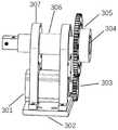
优选地,所述软镜旋转模块包括第二步进电机、滑台固定架、步进电机连接齿轮、力反馈装置、旋转轴连接齿轮、旋转轴、第一旋转轴固定支架和第二旋转轴固定支架;其中:Preferably, the soft mirror rotation module includes a second stepping motor, a sliding table fixing frame, a stepping motor connecting gear, a force feedback device, a rotating shaft connecting gear, a rotating shaft, a first rotating shaft fixing bracket and a second rotating shaft fixing bracket; of which:
所述第二步进电机和第二旋转轴固定支架紧固连接,所述滑台固定架的底端与所述软镜推送模块紧固连接,所述滑台固定架的上端分别与第一旋转轴固定支架和第二旋转轴固定支架紧固连接,所述第二步进电机的旋转轴与步进电机连接齿轮紧固连接,所述步进电机连接齿轮和旋转轴连接齿轮啮合传动,所述旋转轴切分为两部分,所述力反馈装置设置于旋转轴的两部分之间,并通过力反馈装置的两个受力面与旋转轴的两部分连接,所述旋转轴通过轴承分别嵌入在第一旋转轴固定支架和第二旋转轴固定支架的内部;所述第二步进电机的旋转运动通过步进电机连接齿轮和旋转轴连接齿轮传递到旋转轴,所述力反馈装置实时反馈输尿管软镜运动过程中的力值信息。The second stepping motor and the second rotating shaft fixing bracket are tightly connected, the bottom end of the sliding table fixing frame is tightly connected with the soft mirror push module, and the upper end of the sliding table fixing frame is respectively connected with the first The rotating shaft fixing bracket and the second rotating shaft fixing bracket are tightly connected, the rotating shaft of the second stepping motor is tightly connected with the stepping motor connecting gear, and the stepping motor connecting gear and the rotating shaft connecting gear are engaged for transmission, The rotating shaft is divided into two parts, the force feedback device is arranged between the two parts of the rotating shaft, and is connected with the two parts of the rotating shaft through the two force surfaces of the force feedback device, and the rotating shaft passes through the bearing. respectively embedded in the first rotating shaft fixing bracket and the second rotating shaft fixing bracket; the rotational motion of the second stepping motor is transmitted to the rotating shaft through the stepping motor connecting gear and the rotating shaft connecting gear, and the force feedback device Real-time feedback of force value information during the movement of flexible ureteroscope.
优选地,所述软镜弯曲模块包括第三步进电机、步进电机固定架,软镜搭载平台、U型旋钮和软镜固定架;其中:Preferably, the flexible lens bending module includes a third stepping motor, a stepping motor fixing frame, a flexible lens mounting platform, a U-shaped knob and a flexible lens fixing frame; wherein:
所述第三步进电机和步进电机固定架紧固连接,输尿管软镜放置于软镜搭载平台上,并通过软镜固定架固定输尿管软镜的位置,所述软镜搭载平台紧固于软镜旋转模块的旋转轴上,软镜旋转模块的旋转轴的转动带动软镜搭载平台旋转,从而带动输尿管软镜旋转,U型旋钮的一端和第三步进电机的旋转轴连接,U型旋钮的另一端卡在输尿管软镜的弯曲旋钮上,U型旋钮随着第三步进电进旋转,软镜的弯曲旋钮被U型旋钮带动,从而致使软镜末端弯曲。The third stepper motor and the stepper motor fixing frame are fastened and connected, the flexible ureteroscope is placed on the flexible scope carrying platform, and the position of the flexible ureteroscope is fixed by the flexible mirror fixing frame, and the flexible ureteroscope carrying platform is fastened on the flexible scope. On the rotating shaft of the flexible mirror rotating module, the rotation of the rotating shaft of the flexible mirror rotating module drives the flexible mirror carrying platform to rotate, thereby driving the flexible ureteroscope to rotate. One end of the U-shaped knob is connected to the rotating shaft of the third stepper motor. The U-shaped The other end of the knob is clamped on the bending knob of the flexible ureteroscope, the U-shaped knob rotates with the third step, and the bending knob of the flexible scope is driven by the U-shaped knob, so that the end of the flexible scope is bent.
优选地,还包括计算机远程控制系统,所述计算机远程控制系统分别与软镜升降模块的升降台、软镜推送模块的第一步进电机、软镜旋转模块的第二步进电机和软镜弯曲模块的第三步进电机控制连接。Preferably, it also includes a computer remote control system, the computer remote control system is respectively connected with the lifting platform of the soft mirror lifting module, the first stepping motor of the soft mirror pushing module, the second stepping motor of the soft mirror rotating module, and the soft mirror The third stepper motor control connection of the bending module.
本发明上述泌尿外科微创介入手术机器人,包括输尿管软镜升降模块,软镜推送模块,软镜旋转模块以及软镜弯曲模块。软镜升降模块包括升降台,直线模组固定架,升降台可以调整输尿管软镜与病床的高度,固定架连接升降台和直线模组;软镜推送模块包括推送机构以及软镜支撑机构,可以推送输尿管软镜,支撑机构负责给输尿管软镜提供柔性部分的支撑力;软镜旋转模块包括旋转轴和齿轮,所述软镜旋转模块通过电机的旋转带动旋转轴的旋转;软镜弯曲模块包括软镜固定支架,软镜搭载平台以及U型旋钮,所述U型旋钮与软镜弯曲旋钮匹配,使软镜弯曲旋钮随着U型旋钮的旋转而一起旋转。The above-mentioned urological minimally invasive interventional operation robot of the present invention includes a flexible ureteroscope lifting module, a flexible scope pushing module, a flexible scope rotating module and a flexible scope bending module. The soft mirror lifting module includes a lifting table and a linear module fixing frame. The lifting table can adjust the height of the flexible ureteroscope and the hospital bed. The fixing frame is connected to the lifting table and the linear module. The soft mirror pushing module includes a push mechanism and a soft mirror support mechanism. The flexible ureteroscope is pushed, and the supporting mechanism is responsible for providing the support force of the flexible part for the flexible ureteroscope; the flexible scope rotation module includes a rotating shaft and a gear, and the flexible scope rotation module drives the rotation of the rotating shaft through the rotation of the motor; the flexible scope bending module includes The flexible lens fixing bracket, the flexible lens mounting platform and the U-shaped knob are matched with the flexible lens bending knob, so that the flexible lens bending knob rotates together with the rotation of the U-shaped knob.
与现有技术相比,本发明具有如下有益效果:Compared with the prior art, the present invention has the following beneficial effects:
1、本发明提供的泌尿外科微创介入手术机器人,同时包括软镜升降模块、软镜推送模块、软镜旋转模块以及软镜弯曲模块,可以实现输尿管软镜的高度调整,输尿管软镜的推送,旋转和弯曲。1. The urological minimally invasive interventional surgery robot provided by the present invention also includes a flexible scope lifting module, a flexible scope pushing module, a flexible scope rotating module and a flexible scope bending module, which can realize the height adjustment of the flexible ureteroscope and the pushing of the flexible ureteroscope. , rotate and bend.
2、本发明将软镜推送模块固定于软镜升降模块上,软镜升降模块可以根据需要调整输尿管软镜高度,使其与病床高度平齐,医生无需在站立状态下手持输尿管软镜进行手术,有效缓解医生在手术过程中由于操作姿势引起的疲劳。2. In the present invention, the flexible mirror push module is fixed on the flexible mirror lifting module, and the flexible mirror lifting module can adjust the height of the flexible ureteroscope as required to make it flush with the height of the hospital bed, and the doctor does not need to hold the flexible ureteroscope for surgery in a standing state. , effectively relieve the fatigue caused by the operation posture of the doctor during the operation.
3、本发明能够帮助医生完成在手术过程中进行的相应软镜操作,缓解医生长时间手术的疲劳,提升手术速度,并且能够在手术过程中采集软镜运动的力数据。3. The present invention can help the doctor to complete the corresponding flexible endoscope operation during the operation, relieve the fatigue of the doctor during the long-term operation, improve the operation speed, and can collect the force data of the flexible endoscope movement during the operation.
4、本发明还能够远程对输尿管软镜进行操作,以缓解医生在手术过程中由于操作姿势引起的疲劳。4. The present invention can also remotely operate the flexible ureteroscope, so as to relieve the fatigue caused by the operation posture of the doctor during the operation.
5、本发明设置力反馈装置,医生在操作过程中,通过输尿管软镜介入机器人系统上的力反馈装置(力传感器)测量阻力信息,在主手端能够反馈此阻力给医生,使医生感觉是亲自拿着输软管软镜在做手术。5. The present invention is provided with a force feedback device. During the operation, the doctor measures the resistance information through the force feedback device (force sensor) on the flexible ureteroscope intervention robot system, and can feedback this resistance to the doctor at the main hand end, so that the doctor feels I am doing surgery with a flexible tube endoscope in person.
附图说明Description of drawings
通过阅读参照以下附图对非限制性实施例所作的详细描述,本发明的其它特征、目的和优点将会变得更明显:Other features, objects and advantages of the present invention will become more apparent by reading the detailed description of non-limiting embodiments with reference to the following drawings:
图1为本发明一优选实施例的整体结构示意图;1 is a schematic diagram of the overall structure of a preferred embodiment of the present invention;
图2为本发明一优选实施例的软镜升降模块结构示意图;2 is a schematic structural diagram of a flexible mirror lifting module according to a preferred embodiment of the present invention;
图3为本发明一优选实施例的软镜推送模块结构示意图;3 is a schematic structural diagram of a soft mirror push module according to a preferred embodiment of the present invention;
图4为本发明一优选实施例的软镜旋转模块结构示意图;4 is a schematic structural diagram of a flexible mirror rotation module according to a preferred embodiment of the present invention;
图5为本发明一优选实施例的软镜弯曲模块结构示意图;5 is a schematic structural diagram of a flexible mirror bending module according to a preferred embodiment of the present invention;
图中:In the picture:
1为软镜升降模块,2为软镜推送模块,3为软镜旋转模块,4为软镜弯曲模块。1 is the soft mirror lifting module, 2 is the soft mirror pushing module, 3 is the soft mirror rotating module, and 4 is the soft mirror bending module.
101为直线模组前端固定支架,102为直线模组后端固定支架,103为升降台;101 is the front end fixing bracket of the linear module, 102 is the rear end fixing bracket of the linear module, and 103 is the lifting platform;
201为软镜支撑模块,202为第一滑台,203为直线模组,204为第二滑台,205为第一步进电机;201 is the soft mirror support module, 202 is the first sliding stage, 203 is the linear module, 204 is the second sliding stage, and 205 is the first step motor;
301为第二步进电机,302为滑台固定架,303为步进电机连接齿轮,304为力反馈装置,305为旋转轴连接齿轮,306为旋转轴,307为旋转轴固定架,308为旋转轴固定架;301 is the second stepping motor, 302 is the sliding table fixing frame, 303 is the stepping motor connecting gear, 304 is the force feedback device, 305 is the rotating shaft connecting gear, 306 is the rotating shaft, 307 is the rotating shaft fixing frame, 308 is the Rotary shaft holder;
401为第三步进电机,402为步进电机固定架,403为软镜搭载平台,404为U型旋钮,405为软镜固定架。401 is a third stepping motor, 402 is a stepping motor fixing frame, 403 is a flexible mirror mounting platform, 404 is a U-shaped knob, and 405 is a flexible mirror fixing frame.
具体实施方式Detailed ways
下面对本发明的实施例作详细说明:本实施例在以本发明技术方案为前提下进行实施,给出了详细的实施方式和具体的操作过程。应当指出的是,对本领域的普通技术人员来说,在不脱离本发明构思的前提下,还可以做出若干变形和改进,这些都属于本发明的保护范围。The embodiments of the present invention are described in detail below: This embodiment is implemented on the premise of the technical solution of the present invention, and provides detailed implementation modes and specific operation processes. It should be pointed out that for those skilled in the art, without departing from the concept of the present invention, several modifications and improvements can be made, which all belong to the protection scope of the present invention.
如图1至图5所示,一种泌尿外科微创介入手术机器人的部分实施例示意图。As shown in FIG. 1 to FIG. 5 , schematic diagrams of some embodiments of a minimally invasive interventional robot for urology.
如图1所示,一种泌尿外科微创介入手术机器人,包括:软镜升降模块1、软镜推送模块2、软镜旋转模块3、软镜弯曲模块4;其中:As shown in Figure 1, a minimally invasive interventional robot for urology includes: a flexible
软镜升降模块1,用于调整输尿管软镜的垂直高度;The flexible
软镜推送模块2,设置于所述软镜升降模块1上,用于调整输尿管软镜水平运动距离,实现输尿管软镜的推送操作;The flexible
软镜旋转模块3,设置于所述软镜推送模块2上,用于输尿管软镜的旋转操作,所述软镜旋转模块3上设有力反馈装置,实时反馈输尿管软镜运动过程中的力值信息;The flexible
软镜弯曲模块4,设置于所述软镜旋转模块3上,通过U型旋钮404的旋转运动带动输尿管软镜前端弯曲。The flexible
在本发明的一个实施例中,上述各个模块之间可以通过如下方式进行连接:In an embodiment of the present invention, the above modules may be connected in the following manner:
所述软镜升降模块1设有直线模组前端固定支架101和直线模组后端固定支架102,所述软镜推送模块2通过所述直线模组前端固定支架101和直线模组后端固定支架102与软镜升降模块1连接;The flexible
所述软镜推送模块2设有滑台与所述软镜旋转模块3连接;The soft
所述软镜旋转模块3设有旋转轴306,通过旋转轴306上的螺纹孔与软镜弯曲模块4相连接;The flexible
所述软镜升降模块1、所述软镜推送模块2、所述软镜旋转模块3与所述软镜弯曲模块4实现输尿管软镜的升降、推送、旋转以及软镜末端弯曲运动。The flexible
通过上述的连接方式,所述的软镜推送模块2固定于所述的软镜升降模块1,所述的软镜推送模块2随着所述的软镜升降模块1一起在垂直方向上进行运动,所述的软镜旋转模块3固定于所述的软镜推送模块2上,一起进行水平方向上的运动,所述软镜弯曲模块4固定于所述的软镜旋转模块3上,软镜弯曲模块4随着软镜旋转模块3的旋转而一起旋转。Through the above connection method, the soft
如图2所示,在本发明的一个实施例中,所述软镜升降模块1可以采用如下结构:As shown in FIG. 2, in an embodiment of the present invention, the flexible
所述软镜升降模块1包括直线模组前端固定架101、,直线模组后端固定架102和升降台103。The flexible
升降台103作为整个机器人系统的底座,软镜推送模块2通过直线模组前端固定架101和直线模组后端固定架102固定。The lift table 103 is used as the base of the entire robot system, and the soft
具体的:specific:
直线模组前端固定架101的其中一端采用螺母固定在升降台103上,另一端螺母固定在软镜推送模块2上,直线模组后端固定架102的一端螺母固定在升降台103,另一端螺母固定在软镜推送模块2上,升降台103的升降运动带动软镜推送模块2升降。One end of the front
以上是本发明中所述软镜升降模块1的优选结构设计的一种,当然在其他实施例中,所述软镜升降模块1也可以是其他的结构,只要能够起到上述相同的作用即可,并不局限于上述的结构。The above is one of the preferred structural designs of the flexible
如图3所示,在本发明的一个实施例中,所述软镜推送模块2可以采用如下结构:As shown in FIG. 3, in an embodiment of the present invention, the soft
所述软镜推送模块2包括软镜支撑模块201、第一滑台202、直线模组203、第二滑台204、第一步进电机205;The soft
软镜支撑模块201通过紧固螺母和第一滑台202紧密固定,软镜旋转模块3通过紧固螺母和第二滑台204固定,第一滑台202和第二滑台204嵌在直线模组203的丝杆上,直线模组203的丝杆的末端通过联轴器与第一步进电机205的输出轴连接。第一步进电机205的旋转运动通过丝杆转化为直线水平运动,嵌在丝杆上的第一滑台202和第二滑台204随着丝杆的旋转在水平方向进行运动。The flexible
以上是本发明中所述软镜推送模块2的优选结构设计的一种,当然在其他实施例中,所述软镜推送模块2也可以是其他的结构,只要能够起到上述相同的作用即可,并不局限于上述的结构。The above is one of the preferred structural designs of the soft
如图4所示,在本发明的一个实施例中,所述软镜旋转模块3可以采用如下结构:As shown in FIG. 4 , in an embodiment of the present invention, the flexible
所述软镜旋转模块3包括第二步进电机301、滑台固定架302、步进电机连接齿轮303、力反馈装置(力传感器)304、旋转轴连接齿轮305、旋转轴306、第一旋转轴固定支架307以及第二旋转轴固定支架308;The soft
第二步进电机301通过螺母和第二旋转轴固定支架308紧固连接,滑台固定架302底端与所述软镜推送模块2通过螺母紧固连接,滑台固定架302上端与第一旋转轴固定支架307和第二旋转轴固定支架308紧固连接,第二步进电机301的旋转轴与步进电机连接齿轮303通过基米螺丝紧固连接,步进电机连接齿轮303和旋转轴连接齿轮305啮合传动,力反馈装置304与旋转轴306连接,旋转轴306通过轴承嵌入在第一旋转轴固定支架307和第二旋转轴固定支架308的内部,因此第二步进电机301的旋转运动通过步进电机连接齿轮303和旋转轴连接齿轮305传递到旋转轴306。The
上述实施例通过设置力反馈装置,能够有效解决现有泌尿外科微创手术过程中医生无法感知运动时阻力的问题。但是,如果将现有的力反馈装置直接安装于泌尿外科微创介入手术机器人上,势必会增大整个装置的体积,导致无法满足手术需求。因此,泌尿外科微创手术中始终未能解决通过采用力反馈装置实现医生手术过程中力度感知的问题。而本实施例通过对力反馈装置进行如下设置,成功解决了上述问题。The above embodiment can effectively solve the problem that the doctor cannot perceive the resistance during movement during the existing minimally invasive urological surgery by setting the force feedback device. However, if the existing force feedback device is directly installed on the minimally invasive interventional surgical robot in urology, the volume of the entire device will inevitably increase, resulting in the inability to meet the surgical needs. Therefore, in the minimally invasive urological surgery, the problem of realizing the force perception of the doctor during the operation by using the force feedback device has never been solved. In this embodiment, the above problems are successfully solved by setting the force feedback device as follows.
上述实施例中,力反馈装置304的两个受力面都各有两个螺纹孔,旋转轴306被切分成了两部分,旋转轴306一部分通过螺母与力反馈装置304的一端连接,另一部分同样通过螺母与力反馈装置另一端相连接,这样力反馈装置相当于嵌入在旋转轴306中,因此体积可以通过缩短旋转轴的长度达到与没加力反馈装置时的体积相同的效果。In the above embodiment, the two force-receiving surfaces of the
上述实施例首次在泌尿外科微创手术系统中使用力反馈装置,解决了如下技术问题:The above-mentioned embodiment uses the force feedback device in the urological minimally invasive surgery system for the first time, and solves the following technical problems:
1、在没有增大泌尿外科微创介入手术机器人体积的情况下(即不影响手术需求的情况下),解决了手术过程中医生实时感知输尿管软镜运动阻力的问题;1. Without increasing the volume of the robot for minimally invasive interventional surgery in urology (that is, without affecting the needs of surgery), the problem of real-time perception of the motion resistance of the flexible ureteroscope during the operation is solved;
2、同时解决了医生无法定量知道输尿管软镜运动过程中阻力大小的问题。在上述实施例中,所述力反馈装置304与泌尿外科微创介入手术的操作相关的工作过程为:当泌尿外科微创介入手术机器人前进时,输尿管软镜前端所受到的阻力会传递到旋转轴306,旋转轴306和力反馈装置304固定,从而将阻力传递到力反馈装置304上,力反馈装置304通过电压信号的大小反映阻力大小,通过数据采集卡将电压信号采集传入电脑,电脑中经过电压与阻力的对应关系计算获得力值,显示在电脑上并传给主手。2. At the same time, it solves the problem that the doctor cannot quantitatively know the resistance during the movement of the flexible ureteroscope. In the above embodiment, the working process of the
以上是本发明中所述软镜旋转模块3的优选结构设计的一种,当然在其他实施例中,所述导丝推送模块3也可以是其他的结构,只要能够起到上述相同的作用即可,并不局限于上述的结构。The above is one of the preferred structural designs of the flexible
如图5所示,在本发明的一个实施例中,所述软镜弯曲模块4可以采用如下结构:As shown in FIG. 5 , in an embodiment of the present invention, the flexible
所述软镜弯曲模块4包括第三步进电机401、步进电机固定架402,软镜搭载平台403、U型旋钮404和软镜固定架405;The flexible
第三步进电机401通过螺母螺栓和步进电机固定架402紧固连接,软镜放置于软镜搭载平台403上,通过软镜固定架405固定软镜位置,软镜搭载平台403通过螺母紧固于软镜旋转模块3的旋转轴306上,软镜旋转模块3的旋转轴306的转动带动软镜搭载平台403旋转,从而带动软镜旋转,U型旋钮404的一端通过基米螺丝和第三步进电机401的旋转轴连接,U型旋钮404的另一端卡在软镜的弯曲旋钮上,U型旋钮404随着第三步进电进401旋转,软镜的弯曲旋钮被U型旋钮404带动,从而导致软镜末端弯曲。The
以上是本发明中所述软镜弯曲模块4的优选结构设计的一种,当然在其他实施例中,所述软镜弯曲模块4也可以是其他的结构,只要能够起到上述相同的作用即可,并不局限于上述的结构。The above is one of the preferred structural designs of the flexible
需要补充的是:上述各个优选的实施结构,可以单独使用,在互不冲突时可以多个优选结构任意组合使用,组合使用时效果更好。It should be added that the above-mentioned preferred implementation structures can be used alone, or can be used in any combination of a plurality of preferred structures when they do not conflict with each other, and the combined use is more effective.
为了更清楚地了解本发明的工作情况,以下结合上述各个优选技术特征详细描述本发明所述机器人系统的工作过程。In order to understand the working situation of the present invention more clearly, the working process of the robot system of the present invention will be described in detail below with reference to the above-mentioned preferred technical features.
所述泌尿外科微创介入手术机器人通过以下步骤实现术前输尿管软镜升降、术中输尿管软镜推送、旋转以及弯曲的过程:The urology minimally invasive interventional surgery robot realizes the preoperative lifting and lowering of the flexible ureteroscope, the pushing, rotation and bending of the flexible ureteroscope during the operation through the following steps:
1.首先将所述机器人系统进行消毒处理,并安装调试好;调试好所述机器人系统的控制程序后,将输尿管软镜放置到软镜固定架405处,并将软镜固定架405固定到软镜搭载平台403;1. The robot system is firstly disinfected, installed and debugged; after the control program of the robot system is debugged, the flexible ureteroscope is placed on the
2.通过计算机控制程序中输入升降台高度信息,控制升降台103的高度,通过遥控方式微调升降台103;2. Input the height information of the elevator platform through the computer control program, control the height of the
3.通过计算机控制第一步进电机205正向旋转,实现推送软镜的功能:3. The
具体实施时,先使远程通信接通,计算机控制程序中输入推送参数,包括:软镜推送速度;During the specific implementation, the remote communication is first connected, and the push parameters are input in the computer control program, including: soft mirror push speed;
所述机器人接受对应指令后,医生在主端操作主手,主手在x轴方向运动数据传给第一步进电机205,此时第一步进电机205旋转,第一步进电机205通过联轴器带动直线模组203的丝杆旋转运动,丝杆的旋转运动带动第一滑台202和第二滑台204进行水平运动,第一滑台202和第二滑台204的相对距离固定。After the robot receives the corresponding instruction, the doctor operates the main hand on the main end, and the movement data of the main hand in the x-axis direction is transmitted to the
4.软镜推送过程中,主手的y轴方向运动数据会传送到第二步进电机301中:4. During the soft mirror push process, the movement data of the main hand in the y-axis direction will be transmitted to the second stepper motor 301:
具体实施时,计算机控制第二步进电机301的转速,第二步进电机301通过输出轴与步进电机连接齿轮303连接,并通过步进电机连接齿轮303和旋转轴连接齿轮305的传动,进而带动旋转轴306,实现相应的旋转,旋转轴306末端连接力反馈装置304,软镜运动过程的受力传至旋转轴306后传到力反馈装置304上,计算机界面显示力数据。In specific implementation, the computer controls the rotational speed of the
5.软镜推送和旋转过程中,主手的z轴方向运动数据会传送到第三步进电机401中:5. During the push and rotation of the soft mirror, the movement data of the main hand in the z-axis direction will be transmitted to the third stepper motor 401:
具体实施时,计算机控制第三步进电机401的转速,第三步进电机轴的转动带动基米螺丝固定的U型旋钮404转动,U型旋钮404卡在软镜的弯曲旋钮上,当U型旋钮404转动时,软镜的弯曲旋钮也随之旋转,从而导致软镜末端弯曲。During specific implementation, the computer controls the rotational speed of the
在本实施例中:In this example:
软镜升降模块、软镜推送模块、软镜旋转模块以及软镜弯曲模块相互协作运动,可以实现输尿管软镜的高度调整,输尿管软镜的推送,旋转和弯曲。The flexible scope lifting module, flexible scope pushing module, flexible scope rotating module and flexible scope bending module move in cooperation with each other, which can realize the height adjustment of the flexible ureteroscope, the pushing, rotation and bending of the flexible ureteroscope.
软镜升降模块可以根据需要调整输尿管软镜高度,使其与病床高度平齐。The flexible mirror lifting module can adjust the height of the flexible ureteroscope according to the needs to make it flush with the height of the hospital bed.
软镜推送模块通过直线模组的前进实现软镜的水平运动,软镜相对于直线模组的高度固定。The soft mirror push module realizes the horizontal movement of the soft mirror through the advancement of the linear module, and the height of the soft mirror relative to the linear module is fixed.
软镜旋转模块将电机轴、齿轮和旋转轴之间进行连接,通过齿轮传动,电机带动旋转轴旋转。The soft mirror rotation module connects the motor shaft, the gear and the rotating shaft, and through the gear transmission, the motor drives the rotating shaft to rotate.
软镜弯曲模块包含软镜搭载平台、软镜固定支架和U型旋钮,U型旋钮可以根据需要旋转,可以连接软镜的弯曲旋钮,对软镜末端进行弯曲操作。The flexible lens bending module includes a flexible lens mounting platform, a flexible lens fixing bracket and a U-shaped knob. The U-shaped knob can be rotated as required, and can be connected to the flexible lens bending knob to bend the end of the flexible lens.
软镜旋转模块具有力反馈装置,放置于旋转轴后端,实时采集数据。The soft mirror rotation module has a force feedback device, which is placed at the rear end of the rotation axis to collect data in real time.
本发明上述实施例所述泌尿外科微创介入手术机器人,能够协助医生远程对输尿管软镜进行操作,以缓解医生由于操作姿势引起的疲劳并且能采集手术过程中的力觉数据,增加手术过程的精确性。The urological minimally invasive interventional surgery robot described in the above-mentioned embodiments of the present invention can assist the doctor to remotely operate the flexible ureteroscope, so as to relieve the fatigue caused by the operation posture of the doctor, and can collect the force sense data during the operation, thereby increasing the operation time. precision.
以上对本发明的具体实施例进行了描述。需要理解的是,本发明并不局限于上述特定实施方式,本领域技术人员可以在权利要求的范围内做出各种变形或修改,这并不影响本发明的实质内容。The specific embodiments of the present invention have been described above. It should be understood that the present invention is not limited to the above-mentioned specific embodiments, and those skilled in the art can make various variations or modifications within the scope of the claims, which do not affect the essential content of the present invention.
Claims (4)
Priority Applications (1)
| Application Number | Priority Date | Filing Date | Title |
|---|---|---|---|
| CN201811078869.2ACN109044533B (en) | 2018-09-17 | 2018-09-17 | Minimally invasive interventional operation robot for urinary surgery |
Applications Claiming Priority (1)
| Application Number | Priority Date | Filing Date | Title |
|---|---|---|---|
| CN201811078869.2ACN109044533B (en) | 2018-09-17 | 2018-09-17 | Minimally invasive interventional operation robot for urinary surgery |
Publications (2)
| Publication Number | Publication Date |
|---|---|
| CN109044533A CN109044533A (en) | 2018-12-21 |
| CN109044533Btrue CN109044533B (en) | 2020-07-28 |
Family
ID=64762622
Family Applications (1)
| Application Number | Title | Priority Date | Filing Date |
|---|---|---|---|
| CN201811078869.2AActiveCN109044533B (en) | 2018-09-17 | 2018-09-17 | Minimally invasive interventional operation robot for urinary surgery |
Country Status (1)
| Country | Link |
|---|---|
| CN (1) | CN109044533B (en) |
Families Citing this family (19)
| Publication number | Priority date | Publication date | Assignee | Title |
|---|---|---|---|---|
| CN110141365B (en)* | 2019-05-06 | 2021-01-26 | 清华大学 | Blood vessel intervention operation auxiliary device remote control system for simulating doctor operation |
| CN110269684B (en)* | 2019-06-18 | 2021-08-13 | 上海交通大学 | A flexible surgical terminal module and a flexible robot for minimally invasive surgery of the larynx |
| CN110721380B (en)* | 2019-11-18 | 2022-07-05 | 北京大学人民医院(北京大学第二临床医学院) | Device capable of automatically implementing trachea cannula |
| CN110882059A (en)* | 2019-12-27 | 2020-03-17 | 天机医用机器人技术(清远)有限公司 | A medical multifunctional puncture positioning endoscope manipulator |
| CN111012298A (en)* | 2019-12-27 | 2020-04-17 | 深圳市越疆科技有限公司 | Ureteroscope fixture and ureteroscope robot |
| CN111557738B (en)* | 2020-01-14 | 2023-03-21 | 杭州法博激光科技有限公司 | Control system of soft lens auxiliary device |
| CN111658149B (en)* | 2020-06-19 | 2021-06-01 | 张学斌 | Percutaneous nephroscope operation robot execution system and executor |
| CN113662500B (en)* | 2021-08-23 | 2025-03-28 | 哈尔滨佩同科技发展有限公司 | Digestive endoscopy robot |
| CN114224269A (en)* | 2021-12-13 | 2022-03-25 | 复旦大学 | Automatically controlled drive integration electron soft mirror device of trachea cannula robot |
| CN114366303B (en)* | 2021-12-27 | 2024-03-15 | 北京双翼麒电子有限公司 | Endoscope robot and endoscope operating system |
| CN114391946A (en)* | 2022-01-14 | 2022-04-26 | 苏州欧畅医疗科技有限公司 | Interventional robot and using method thereof |
| CN114569249B (en)* | 2022-02-28 | 2023-10-31 | 复旦大学 | A soft scope delivery device for complex airway intubation robots |
| CN114668509B (en)* | 2022-03-07 | 2025-02-25 | 上海交通大学 | A soft-scope interventional surgical robot system with force feedback function |
| CN115486941B (en)* | 2022-11-16 | 2023-03-24 | 江西卓瑞科技有限公司 | Ureter soft mirror robot |
| CN115813564B (en)* | 2023-02-23 | 2024-01-09 | 之江实验室 | Bending mechanisms and surgical robots |
| CN116058962A (en)* | 2023-02-23 | 2023-05-05 | 之江实验室 | Rotating mechanism and surgical robot |
| CN116269780B (en)* | 2023-02-23 | 2023-10-10 | 之江实验室 | Feeding mechanism and surgical robot |
| CN118902616A (en)* | 2023-05-06 | 2024-11-08 | 中国医科大学附属第一医院 | Ureteroscope operation robot |
| CN118304000B (en)* | 2024-04-08 | 2025-09-30 | 福州大学 | A ureteroscopic surgical robot with multi-instrument collaborative operation |
Citations (3)
| Publication number | Priority date | Publication date | Assignee | Title |
|---|---|---|---|---|
| CN1939230A (en)* | 2005-09-30 | 2007-04-04 | 伊西康内外科公司 | Surgical stapling instrument having load sensing control circuitry |
| CN102091379A (en)* | 2011-01-17 | 2011-06-15 | 哈尔滨工业大学 | Catheter intervention device with conveying resistance feedback function |
| CN207125756U (en)* | 2016-12-20 | 2018-03-23 | 中国人民解放军南京军区南京总医院 | Medical portable air bag pressure measuring and regulating device |
Family Cites Families (7)
| Publication number | Priority date | Publication date | Assignee | Title |
|---|---|---|---|---|
| US10537713B2 (en)* | 2009-05-25 | 2020-01-21 | Stereotaxis, Inc. | Remote manipulator device |
| CN105596084B (en)* | 2016-02-02 | 2018-11-16 | 上海交通大学 | Cardiovascular interventional operation robot |
| CN106420018B (en)* | 2016-11-29 | 2023-08-11 | 哈尔滨理工大学 | A Synchronous Puncture Mechanism of Cannula Flexible Needle Based on Gear Transmission |
| CN106983560B (en)* | 2017-04-20 | 2023-07-25 | 广州泰晶智能科技有限公司 | Soft mirror operation auxiliary robot system |
| CN207605009U (en)* | 2017-04-20 | 2018-07-13 | 广州泰晶智能科技有限公司 | A kind of soft lens operation auxiliary robot with movable support frame |
| CN107307909B (en)* | 2017-07-06 | 2018-11-27 | 北京理工大学 | A kind of intervention robot remote operating system |
| CN107374740B (en)* | 2017-07-06 | 2018-09-11 | 北京理工大学 | A kind of catheter guide wire cooperating intervention robot |
- 2018
- 2018-09-17CNCN201811078869.2Apatent/CN109044533B/enactiveActive
Patent Citations (3)
| Publication number | Priority date | Publication date | Assignee | Title |
|---|---|---|---|---|
| CN1939230A (en)* | 2005-09-30 | 2007-04-04 | 伊西康内外科公司 | Surgical stapling instrument having load sensing control circuitry |
| CN102091379A (en)* | 2011-01-17 | 2011-06-15 | 哈尔滨工业大学 | Catheter intervention device with conveying resistance feedback function |
| CN207125756U (en)* | 2016-12-20 | 2018-03-23 | 中国人民解放军南京军区南京总医院 | Medical portable air bag pressure measuring and regulating device |
Also Published As
| Publication number | Publication date |
|---|---|
| CN109044533A (en) | 2018-12-21 |
Similar Documents
| Publication | Publication Date | Title |
|---|---|---|
| CN109044533B (en) | Minimally invasive interventional operation robot for urinary surgery | |
| CN103356295B (en) | Soft lens operation aided arm prosthesis system and control method thereof | |
| CN102028549B (en) | Catheter robot system for minimally invasive interventional operation in blood vessel | |
| CN111110989B (en) | A guide wire catheter advancing device for vascular interventional surgery | |
| WO2022088535A1 (en) | General-use robot for interventional angiographic and therapeutic surgery | |
| CN103356294B (en) | Auxiliary mechanical arm for soft lens operation | |
| US20210268231A1 (en) | Vascular interventional instrument control device with double guide wires or balloons | |
| CN209474796U (en) | Surgical assistant system suitable for soft lens | |
| CN105283144B (en) | robot manipulator system | |
| CN109452975A (en) | Surgical assistant system suitable for soft lens | |
| CN114191092B (en) | From end delivery device of intervention operation robot | |
| CN113633388B (en) | From end seal wire pipe controlling means of intervention operation robot | |
| CN107744405A (en) | A kind of robot is from end device, operating system and its control method | |
| CN203468740U (en) | Auxiliary manipulator system for flexible ureteroscope operation | |
| CN103399584B (en) | A kind of control system for Long-distance Control medicine equipment and control method thereof | |
| CN203468741U (en) | Flexible cystoscope operation auxiliary manipulator | |
| CN114683314B (en) | Mechanical arm joint, mechanical arm and surgical robot | |
| CN114668509B (en) | A soft-scope interventional surgical robot system with force feedback function | |
| CN117428749A (en) | Power box assembly for surgical robot | |
| CN217162063U (en) | Endoscope rotating wheel driving mechanism and endoscope auxiliary operation device | |
| CN112274178A (en) | A robotic ultrasonic diagnostic device and method based on teleoperation | |
| WO2024098365A1 (en) | Endoscope control apparatus and endoscope robot | |
| CN117562673A (en) | Interventional operation robot | |
| CN115644771B (en) | Endoscope control device and endoscope robot | |
| CN219021532U (en) | Digestive endoscope pushing robot |
Legal Events
| Date | Code | Title | Description |
|---|---|---|---|
| PB01 | Publication | ||
| PB01 | Publication | ||
| SE01 | Entry into force of request for substantive examination | ||
| SE01 | Entry into force of request for substantive examination | ||
| GR01 | Patent grant | ||
| GR01 | Patent grant |