CN109018061B - A Bionics-Based Flexible Passive Foot System - Google Patents
A Bionics-Based Flexible Passive Foot SystemDownload PDFInfo
- Publication number
- CN109018061B CN109018061BCN201810818337.1ACN201810818337ACN109018061BCN 109018061 BCN109018061 BCN 109018061BCN 201810818337 ACN201810818337 ACN 201810818337ACN 109018061 BCN109018061 BCN 109018061B
- Authority
- CN
- China
- Prior art keywords
- foot
- toe
- spring
- shock
- flexible
- Prior art date
- Legal status (The legal status is an assumption and is not a legal conclusion. Google has not performed a legal analysis and makes no representation as to the accuracy of the status listed.)
- Active
Links
- 210000001226toe jointAnatomy0.000claimsabstractdescription63
- 230000006835compressionEffects0.000claimsabstractdescription55
- 238000007906compressionMethods0.000claimsabstractdescription55
- 230000007246mechanismEffects0.000claimsabstractdescription51
- 230000035939shockEffects0.000claimsabstractdescription23
- 235000001968nicotinic acidNutrition0.000claimsabstractdescription20
- 238000010521absorption reactionMethods0.000claimsabstractdescription16
- 230000003139buffering effectEffects0.000claimsabstractdescription14
- 210000002683footAnatomy0.000claimsdescription144
- 210000003371toeAnatomy0.000claimsdescription109
- 230000033001locomotionEffects0.000claimsdescription13
- 210000000452mid-footAnatomy0.000claims1
- 238000011002quantificationMethods0.000claims1
- 230000006870functionEffects0.000abstractdescription9
- 238000004146energy storageMethods0.000abstractdescription5
- 238000000034methodMethods0.000description8
- 230000008569processEffects0.000description6
- 238000010586diagramMethods0.000description5
- 230000005021gaitEffects0.000description5
- 238000002474experimental methodMethods0.000description4
- 238000013016dampingMethods0.000description3
- 238000013461designMethods0.000description3
- 210000002414legAnatomy0.000description3
- 238000005381potential energyMethods0.000description3
- 210000000544articulatio talocruralisAnatomy0.000description2
- 230000008859changeEffects0.000description2
- 238000011161developmentMethods0.000description2
- 230000000694effectsEffects0.000description2
- 238000005265energy consumptionMethods0.000description2
- 210000001503jointAnatomy0.000description2
- 210000000878metatarsophalangeal jointAnatomy0.000description2
- 238000012986modificationMethods0.000description2
- 230000004048modificationEffects0.000description2
- 238000011160researchMethods0.000description2
- 241000282412HomoSpecies0.000description1
- 230000009471actionEffects0.000description1
- 238000007792additionMethods0.000description1
- 210000003423ankleAnatomy0.000description1
- 238000005516engineering processMethods0.000description1
- 210000000474heelAnatomy0.000description1
- 210000001624hipAnatomy0.000description1
- 210000003127kneeAnatomy0.000description1
- 210000003141lower extremityAnatomy0.000description1
- 238000005259measurementMethods0.000description1
- 239000011664nicotinic acidSubstances0.000description1
- 238000005457optimizationMethods0.000description1
- 230000009993protective functionEffects0.000description1
Images


Classifications
- B—PERFORMING OPERATIONS; TRANSPORTING
- B62—LAND VEHICLES FOR TRAVELLING OTHERWISE THAN ON RAILS
- B62D—MOTOR VEHICLES; TRAILERS
- B62D57/00—Vehicles characterised by having other propulsion or other ground- engaging means than wheels or endless track, alone or in addition to wheels or endless track
- B62D57/02—Vehicles characterised by having other propulsion or other ground- engaging means than wheels or endless track, alone or in addition to wheels or endless track with ground-engaging propulsion means, e.g. walking members
- B62D57/032—Vehicles characterised by having other propulsion or other ground- engaging means than wheels or endless track, alone or in addition to wheels or endless track with ground-engaging propulsion means, e.g. walking members with alternately or sequentially lifted supporting base and legs; with alternately or sequentially lifted feet or skid
Landscapes
- Engineering & Computer Science (AREA)
- Chemical & Material Sciences (AREA)
- Combustion & Propulsion (AREA)
- Transportation (AREA)
- Mechanical Engineering (AREA)
- Manipulator (AREA)
Abstract
Translated fromChinese
Description
Translated fromChinese技术领域technical field
本发明涉及一种基于仿生学的柔性被动足部系统,属于机器人技术领域。The invention relates to a flexible passive foot system based on bionics, belonging to the technical field of robotics.
背景技术Background technique
仿人机器人是目前机器人技术发展领域最先进的体现,它们具有类人的外形,在结构和行走方式上也模仿人类。仿人机器人稳定运行的核心技术与研究难点是实现稳定的双足步行。Humanoid robots are the most advanced embodiment of the current development of robotics. They have a human-like shape and imitate humans in structure and walking style. The core technology and research difficulty of the stable operation of humanoid robots is to achieve stable bipedal walking.
从生物力学角度,双足步行可以分为基于主动控制的运动和基于被动行走的运动。这两种方式的缺点在于:能量消耗大,效率低,对驱动器的性能要求较高,步态不自然,与实际人类运动相差较大。未来双足步行机器人的发展趋势,是将主动控制与被动行走相结合,制作出既有较高的效率和自然的步态又能实现多种运动、有较强实用性的机器人。因此将具有柔性的被动足部与各关节主动驱动得双足机器人结合起来,实现主动控制,能获得更高效和更拟人化的双足机器人步行效果。From a biomechanical perspective, bipedal walking can be divided into active control-based movements and passive walking-based movements. The disadvantages of these two methods are: high energy consumption, low efficiency, high performance requirements for the driver, and unnatural gait, which is quite different from the actual human motion. The future development trend of bipedal walking robots is to combine active control with passive walking to produce robots with high efficiency and natural gait, as well as a variety of motions and strong practicability. Therefore, combining a flexible passive foot with a biped robot that is actively driven by each joint to achieve active control can achieve a more efficient and anthropomorphic biped robot walking effect.
中国专利号CN101823517B发明了一种具有足底防滑减震垫和减震六维力矩传感器支座组成的双层减震足部结构,该足部能减小机器人竖直方向上的冲击,但是六维力矩传感器安装在第二层减震座上,测算的足部力矩参数不够准确,同时足部被动自由度比较单一。Chinese Patent No. CN101823517B invented a double-layer shock-absorbing foot structure composed of a sole anti-skid shock-absorbing pad and a shock-absorbing six-dimensional torque sensor support. The foot can reduce the impact of the robot in the vertical direction, but the six The dimensional torque sensor is installed on the second-layer shock-absorbing seat, and the measured foot moment parameters are not accurate enough, and the passive degree of freedom of the foot is relatively simple.
中国专利号CN103738428A发明了一种由跖趾关节、脚跟和踝关节组成的通过扭簧提供柔性的足部结构,该足部具有仿人的跖趾关节,但是足部跖屈时与地面接触为线接触,支撑不稳。同时,该专利中跖趾关节用扭簧提供柔性,在用于实际机器人实验时,贮存于扭簧的能量不便于计算,致使实验的重复性差。Chinese Patent No. CN103738428A invented a foot structure which is composed of metatarsophalangeal joint, heel and ankle joint and provided flexibility through torsion spring. Line contact, support is unstable. At the same time, the metatarsophalangeal joint uses a torsion spring to provide flexibility. When used in an actual robot experiment, the energy stored in the torsion spring is inconvenient to calculate, resulting in poor repeatability of the experiment.
目前普遍的双足机器人足部结构多为刚性结构,以及具有竖直方向或者侧向的单一被动自由度的柔性足部,其中刚性的足部结构对机器人的冲击较大,且步行过程中稳定性也比较差;而采用单一被动自由度的柔性足部,其功能性比较差。在双足机器人领域,要得到运动高效、步态自然、能实现多种步态的双足运动,就需要在双足步行机器人中加入多自由度的被动关节和柔性驱动。At present, the common biped robot foot structures are mostly rigid structures and flexible feet with a single passive degree of freedom in the vertical direction or lateral direction. The rigid foot structure has a greater impact on the robot and is stable during walking. Sex is also relatively poor; and a flexible foot with a single passive degree of freedom has poor functionality. In the field of bipedal robots, in order to obtain bipedal motion with high efficiency, natural gait and realization of various gaits, it is necessary to add passive joints and flexible drives with multiple degrees of freedom to the biped walking robot.
发明内容SUMMARY OF THE INVENTION
本发明主要是为解决现有技术所存在的技术问题而提出了一种可用于双足机器人的基于仿生学的柔性被动足。该足部由被动足趾关节和侧向缓冲减震层组成双层结构,使足部具备了缓冲减震能力、步行过程中的稳定支撑功能以及足趾关节的能量储存能力。柔性被动式的足趾关节能将人体前倾时的能量储存并在单足支撑相末期释放,推动机器人前进,这样将本来在刚性足部中相位切换时消耗于滑动和摩擦的能量储存并利用起来,在理论上能降低机器人的能量消耗。该足部能够缓冲吸震、有效减少驱动电机所承受碰撞产生的瞬时转矩,并且行走步态更加自然;利用其自身固有动力学特性,使机器人具有节能、拟人的特点。The present invention mainly proposes a flexible passive foot based on bionics that can be used for biped robots to solve the technical problems existing in the prior art. The foot is composed of a passive toe joint and a lateral buffering and shock-absorbing layer to form a double-layer structure, so that the foot has a buffering and shock-absorbing capacity, a stable support function during walking, and an energy storage capacity of the toe joint. The flexible passive toe joint can store the energy when the human body leans forward and release it at the end of the monopod support phase to push the robot forward, so that the energy originally consumed by sliding and friction during phase switching in the rigid foot can be stored and utilized. , which can theoretically reduce the energy consumption of the robot. The foot can buffer shock absorption, effectively reduce the instantaneous torque generated by the collision of the driving motor, and the walking gait is more natural; using its own inherent dynamic characteristics, the robot has the characteristics of energy saving and anthropomorphism.
本发明的上述技术问题主要是通过下述技术方案得以解决的:The above-mentioned technical problems of the present invention are mainly solved by the following technical solutions:
一种基于仿生学的柔性被动足部系统,其特征在于,包括仿人被动柔性足趾关节、以及设置在仿人被动柔性足趾关节上的侧向缓冲减震层;所述侧向缓冲减震层通过减震组件设置在仿人被动柔性足趾关节上。A flexible passive foot system based on bionics is characterized in that it comprises a human-like passive flexible toe joint, and a lateral buffering and shock-absorbing layer arranged on the human-like passive flexible toe joint; The shock layer is arranged on the passive flexible toe joint of the humanoid through the shock absorption component.
在上述的一种基于仿生学的柔性被动足部系统,所述仿人足趾关节包括足底、弹簧顶座、弹簧套筒、足趾压缩弹簧、滑块、柔性机构销轴一、足趾连杆、柔性机构销轴二、趾关节销轴、足趾;足趾与足底以铰链的方式连接,通过趾关节销轴固定,足趾关节的弹性由平行于足底的足趾压缩弹簧提供;弹簧顶座、弹簧套筒分别用螺钉相邻固定在足底上,足趾压缩弹簧一端穿过弹簧套筒安装在弹簧顶座上,并且弹簧能始终保持线性压缩,足趾压缩弹簧的另一端与滑块相连;滑块通过柔性机构销轴一与足趾连杆铰接,足趾连杆铰接通过柔性机构销轴二与足趾铰接,滑块、柔性机构销轴一、足趾连杆、柔性机构销轴二与足趾共同组成一个曲柄连杆机构,足趾压缩弹簧通过曲柄连杆机构与足趾连接,此时足趾部分相当于曲柄,压缩弹簧滑块相当于滑动副。In the above-mentioned flexible passive foot system based on bionics, the human toe joint includes a sole, a spring top seat, a spring sleeve, a toe compression spring, a slider, a flexible mechanism pin shaft, a toe Connecting rod,
在上述的一种基于仿生学的柔性被动足部系统,当足趾跖屈时,曲柄连杆机构将足趾的向上的绕销轴的旋转转化为滑块的直线运动,滑块再挤压弹簧,使足趾压缩弹簧呈线性压缩,使弹簧的弹性能线性量化。In the above-mentioned flexible passive foot system based on bionics, when the toes are plantarflexed, the crank link mechanism converts the upward rotation of the toes around the pin shaft into the linear motion of the slider, and the slider is squeezed again. Spring, the toe compression spring is linearly compressed, and the elastic energy of the spring is linearly quantified.
在上述的一种基于仿生学的柔性被动足部系统,足趾关节的机械限位在于:足底部分与足趾部分通过趾关节销轴铰接,足底与足趾部分有机械限位,使得足趾只能绕销轴相对于足底向上旋转;足底的铰接部分的上半部为弧形A1面,下半部为竖直B2面,对应于足趾的上半部a1面和下半部b2面;当足底与足趾铰接在一起,弧形面A1与a1贴合,平面B2与b2贴合产生机械限位,使得足趾只能绕销轴相对足底向上转动,机器人在行走中,摆动腿的足部足趾关节不会向下旋转,与人类足部运动机理保持相似。In the above-mentioned flexible passive foot system based on bionics, the mechanical limit of the toe joint is: the sole part and the toe part are hinged through the toe joint pin, and the sole and the toe part have a mechanical limit, so that The toe can only rotate upwards relative to the sole of the foot around the pin; the upper half of the hinged part of the sole is the arc A1 plane, and the lower half is the vertical B2 plane, corresponding to the a1 plane and the lower half of the toe. Half b2 surface; when the sole and the toe are hinged together, the arc surface A1 fits with a1, and the plane B2 fits with b2 to produce a mechanical limit, so that the toe can only rotate upward relative to the sole around the pin, the robot During walking, the toe joints of the swinging leg do not rotate downward, maintaining a similar mechanism to the human foot.
在上述的一种基于仿生学的柔性被动足部系统,弹簧顶座右端有凸出的圆柱结构,压缩弹簧内圈可穿过此圆柱体结构同时弹簧外圈在套筒内,由于滑块与弹簧顶座的距离限制,当足趾跖屈幅度过大时,滑块左端会与顶座右端接触,从而限制了足部跖屈时,足趾关节的绕销轴向上的旋转角度。In the above-mentioned flexible passive foot system based on bionics, the right end of the spring top seat has a protruding cylindrical structure, and the inner ring of the compression spring can pass through the cylindrical structure while the outer ring of the spring is in the sleeve. The distance of the spring top seat is limited. When the plantar flexion of the toe is too large, the left end of the slider will contact the right end of the top seat, thereby limiting the upward rotation angle of the toe joint around the pin axis when the foot is plantar flexed.
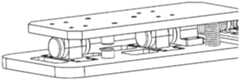
在上述的一种基于仿生学的柔性被动足部系统,所述侧向减震层包括足间销轴、足部上支撑座、足部下支撑座、减震弹簧下支座、减震弹簧上支座、减震弹簧、足部上层;两个足部下支撑座通过螺钉安装在足底上,足部下支撑座通过足间销轴与足部上支撑座铰接,足部上支承座安装在足部上层上,这样足部上下两层通过位于同一轴心线上的两根足间销轴铰接在一起,实现侧向转动,减震弹簧通过减震弹簧下支座、减震弹簧上支座固定,通过压缩实现侧向减震。In the above-mentioned flexible passive foot system based on bionics, the lateral shock absorption layer includes a pin shaft between the feet, an upper foot support seat, a lower foot support seat, a lower shock absorption spring support, and a shock absorption spring upper support. The support, the shock-absorbing spring, the upper layer of the foot; the two lower support seats of the foot are installed on the sole of the foot through screws, the lower support seat of the foot is hinged with the upper support seat of the foot through the pin shaft between the feet, and the upper support seat of the foot is installed on the foot. On the upper layer of the foot, the upper and lower layers of the foot are hinged together through two inter-foot pins located on the same axis line to achieve lateral rotation, and the shock-absorbing spring passes through the lower support of the shock-absorbing spring and the upper support of the shock-absorbing spring Fixed, lateral damping by compression.
在上述的一种基于仿生学的柔性被动足部系统,足部上层和足底各有上下对称的四个减震弹簧安装支座,分别为减震弹簧下支座和减震弹簧上支座,四根减震弹簧两端分别安装在上下支座上,提供减震能力,同时弹簧支座具有一定的长度,限制了足部上层相对与足底的转动角度,避免过度的偏转导致机器人行走故障。In the above-mentioned flexible passive foot system based on bionics, the upper layer of the foot and the sole of the foot each have four shock-absorbing spring mounting supports that are symmetrical up and down, which are respectively the shock-absorbing spring lower support and the shock-absorbing spring upper support , the two ends of the four shock-absorbing springs are respectively installed on the upper and lower supports to provide shock absorption capacity. At the same time, the spring supports have a certain length, which limits the rotation angle between the upper layer of the foot and the sole of the foot, and avoids excessive deflection causing the robot to walk. Fault.
因此,本发明具有如下优点:1.仿人性好,本发明根据仿生学,以人类足部结构为参照,设计了两个被动自由度,该柔性被动足部系统同时具备足趾关节和足部侧向自由度,提高机器人行走在不平地面上的稳定性,适用于复杂地面环境;2.柔性被动足部系统由压缩弹簧提供被动柔性,具备抗冲击和减震作用,对应用本发明的双足机器人下肢关节驱动器具有保护作用,防止因步行冲击造成的硬件损坏,同时弹簧的储能作用将消耗于摩擦和碰撞的能量重新利用,提高能量效率;3.柔性足趾结构中,柔性弹簧平行于足底布置,弹簧压缩线性化,储存的弹性势能便于计算,有助于机器人控制系统的设计和优化;4.足部结构模块化,便于安装拆卸,能快速使用,便于相关领域的研究推广;5.本发明的基于仿生学的柔性被动足部系统结构紧凑,总体质量小,对机器人负载低。Therefore, the present invention has the following advantages: 1. Good human imitation, the present invention designs two passive degrees of freedom based on bionics, taking the structure of the human foot as a reference, and the flexible passive foot system has toe joints and feet at the same time. The lateral degree of freedom improves the stability of the robot walking on uneven ground, and is suitable for complex ground environments; 2. The flexible passive foot system provides passive flexibility by compression springs, and has shock resistance and shock absorption. The lower limb joint driver of the foot robot has a protective function to prevent hardware damage caused by walking impact, and the energy storage function of the spring will reuse the energy consumed in friction and collision to improve energy efficiency; 3. In the flexible toe structure, the flexible springs are parallel It is arranged on the sole of the foot, the spring compression is linearized, and the stored elastic potential energy is easy to calculate, which is helpful for the design and optimization of the robot control system; 4. The foot structure is modular, easy to install and disassemble, and can be used quickly, which is convenient for research and promotion in
附图说明Description of drawings
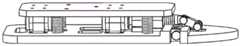
图1是本发明的具有足趾关节的仿生性柔性被动足外观图。FIG. 1 is an external view of the bionic flexible passive foot with toe joints of the present invention.
图2是安装了本发明的柔性被动足的双足机器人外观图。FIG. 2 is an external view of a biped robot equipped with flexible passive feet of the present invention.
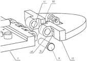
图3(a)是本发明的柔性被动组足趾关节外观图。Figure 3(a) is an external view of the toe joint of the flexible passive group of the present invention.
图3(b)是本发明的柔性被动足部铰接机械限位示意图。Fig. 3(b) is a schematic diagram of the hinged mechanical limit of the flexible passive foot of the present invention.
图3(c)是本发明的柔性被动足部足趾关节跖屈示意图。Figure 3(c) is a schematic diagram of the plantar flexion of the flexible passive foot toe joint of the present invention.
图3(d)是本发明的柔性被动足足部足趾关节的跖屈分析简图。Figure 3(d) is a schematic diagram of the plantar flexion analysis of the toe joint of the flexible passive foot of the present invention.
图4(a)是本发明的柔性被动足侧向缓冲减震层部分的外观图。Fig. 4(a) is an external view of the lateral buffering and shock absorbing layer part of the flexible passive foot of the present invention.
图4(b)是本发明的柔性被动足侧向缓冲减震层部分的后视图。Fig. 4(b) is a rear view of the lateral cushioning and shock-absorbing layer portion of the flexible passive foot of the present invention.
图4(c)是本发明的柔性被动足侧向缓冲减震层部分的爆炸图。Fig. 4(c) is an exploded view of the lateral buffering and shock absorbing layer part of the flexible passive foot of the present invention.
图5是本发明的立体结构示意图。FIG. 5 is a schematic view of the three-dimensional structure of the present invention.
具体实施方式Detailed ways
下面结合附图和本发明具体实施方式的描述,能够更加清楚地了解本发明的细节。但是,在此描述的本发明的具体实施方式,仅用于解释本发明的目的,而不能以任何方式理解成是对本发明的限制。在本发明的教导下,技术人员可以构想基于本发明的任意可能的变形,这些都应被视为属于本发明的范围。图中,仿人被动柔性足趾关节Ⅰ、侧向缓冲减震层Ⅱ、足底1、弹簧顶座2、弹簧套筒3、足趾压缩弹簧4、滑块5、柔性机构销轴一6、足趾连杆7、柔性机构销轴二8、趾关节销轴9、足趾10、足间销轴11、足部上支撑座12、足部下支撑座13、减震弹簧下支座14、减震弹簧上支座15、减震弹簧16、足部上层17。The details of the present invention can be more clearly understood below in conjunction with the accompanying drawings and the description of the specific embodiments of the present invention. However, the specific embodiments of the present invention described herein are only for the purpose of explaining the present invention, and should not be construed as limiting the present invention in any way. Under the teaching of the present invention, the skilled person can conceive any possible modifications based on the present invention, and these should be regarded as belonging to the scope of the present invention. In the figure, humanoid passive flexible toe joint I, lateral buffering and shock absorption layer II, sole 1, spring
一、首先介绍本发明的具体结构。1. First, the specific structure of the present invention is introduced.
本发明由仿人被动柔性足趾关节和侧向缓冲减震层两部分组成。足趾关节的柔性由平行于足底的压缩弹簧提供,并通过曲柄连杆机构连接至足底,使足趾柔性弹簧为线性压缩,从而使实际的实验中相关测算工作更简单高效。同时,这种曲柄连杆机构使得足趾压缩弹簧能平行于足底,弹簧位于足部双层结构中间,能节省空间,使结构紧凑。柔性足趾关节在机器人行走过程中,单腿支撑末期,被动足趾跖屈,足趾弹簧被压缩,储存能量,在单腿支撑末期时,随着机器人向前运动,压缩弹簧伸展,释放能量,产生一个足部蹬地的运动,推动机器人向前,减小踝关节电机功率,有助于机器人行走。The invention is composed of two parts, a passive flexible toe joint of a human being and a lateral buffering and shock-absorbing layer. The flexibility of the toe joint is provided by a compression spring parallel to the sole of the foot, and is connected to the sole of the foot through a crank link mechanism, so that the flexible spring of the toe is compressed linearly, so that the related measurement work in the actual experiment is simpler and more efficient. At the same time, the crank link mechanism enables the toe compression spring to be parallel to the sole of the foot, and the spring is located in the middle of the double-layer structure of the foot, which can save space and make the structure compact. Flexible toe joint In the process of robot walking, at the end of single-leg support, passive toe plantar flexion, the toe spring is compressed, and energy is stored. At the end of single-leg support, as the robot moves forward, the compression spring expands and releases energy , to generate a foot kicking motion, push the robot forward, reduce the motor power of the ankle joint, and help the robot to walk.
弹簧减震层的作用在于:当地面有小角度的额状面上的倾斜,或者凹凸地形时,足部足底发生倾斜,一侧弹簧压缩,足底的倾斜量由弹簧减震层吸收,而足部上层仍保持水平或者不变,在行走的过程保证机器人上层结构不受较小程度的地面条件影响,使机器人行走稳定。足部的双层结构是为了实现侧向的减震,足部结构分为上下两层,由位于中间的销轴机构铰接连在一起,使得足部上下两层能相对侧向转动,同时两侧对称布置了两组减震弹簧,弹簧安装在上下对应的弹簧销上,由减震弹簧的弹性实现侧向减震。The function of the spring damping layer is: when the ground has a small angle of inclination on the frontal surface, or when the terrain is uneven, the sole of the foot is inclined, the spring on one side is compressed, and the inclination of the sole is absorbed by the spring damping layer. While the upper layer of the foot remains level or unchanged, the robot's upper layer structure is not affected by a small degree of ground conditions during the walking process, so that the robot can walk stably. The double-layer structure of the foot is to achieve lateral shock absorption. The foot structure is divided into upper and lower layers, which are hingedly connected by a pin shaft mechanism in the middle, so that the upper and lower layers of the foot can rotate relatively laterally, while the two layers are connected. Two sets of shock-absorbing springs are arranged symmetrically on the side, and the springs are installed on the corresponding upper and lower spring pins, and the side shock is realized by the elasticity of the shock-absorbing spring.
基于仿生学的足趾关节包括:足底、弹簧顶座、弹簧套筒、足趾压缩弹簧、滑块、柔性机构销轴一、足趾连杆、柔性机构销轴二、趾关节销轴、足趾;足部足趾部分为具有弹性的被动结构,足趾与足底以铰链的方式连接,通过趾关节销轴固定,足趾关节的弹性由平行于足底的压缩弹簧提供。弹簧顶座、弹簧套筒分别用螺钉相邻固定在足底上,压缩弹簧穿过弹簧套筒安装在弹簧顶座上,由于套筒的支撑作用和足趾关节的连接特性,弹簧能始终保持线性压缩,足趾压缩弹簧的另一端与滑块相连;滑块通过柔性机构销轴与足趾连杆铰接,足趾连杆铰接通过柔性机构销轴与足趾铰接,这样滑块、柔性机构销轴、足趾连杆、柔性机构销轴与足趾共同组成一个曲柄连杆机构,足趾压缩弹簧通过曲柄连杆机构与足趾部分连接,此时足趾部分相当于曲柄,压缩弹簧滑块相当于滑动副。当足趾进行跖屈时,曲柄连杆机构将足趾的向上的绕铰链的旋转转化为滑块的直线运动,滑块再挤压弹簧,使足趾压缩弹簧呈线性压缩,使弹簧的弹性能线性量化,给实际的实验减少一些不必要的计算工作。同时,这种曲柄连杆机构使得足趾压缩弹簧能平行于足底,弹簧位于足部双层结构中间,能节省空间,使结构紧凑。The toe joint based on bionics includes: sole, spring top seat, spring sleeve, toe compression spring, slider,
在基于仿生学的足部中,足趾关节的机械限位特征在于:足底部分与足趾部分通过销轴铰接,足底与足趾部分有机械限位,使得足趾只能销轴相对于足底向上旋转如图所示。足底的铰接部分结构如图所示,其上半部为弧形A1面,下部为竖直B2平面,对应于足趾的a1和b2。当足底与足趾铰接在一起,弧形面A1与a1贴合,平面B2与b2贴合产生机械限位,使得足趾只能绕销轴相对足底向上转动,机器人在行走中,摆动腿的足部足趾关节不会向下旋转,与人类足部运动机理保持相似。弹簧顶座右端有凸出的圆柱结构,压缩弹簧内圈可穿过此圆柱体结构同时弹簧外圈在套筒内,由于滑块与弹簧顶座的距离限制,当足趾跖屈幅度过大时,滑块左端会与顶座右端接触,从而限制了足趾关节的旋转角度。In the foot based on bionics, the mechanical limit of the toe joint is characterized in that: the sole part and the toe part are hinged through the pin shaft, and the sole and the toe part have a mechanical limit, so that the toe can only be pinned relative to each other. Rotate upward on the sole of the foot as shown. The structure of the hinged part of the sole of the foot is shown in the figure, the upper part is the arc A1 plane, and the lower part is the vertical B2 plane, corresponding to a1 and b2 of the toes. When the sole and the toe are hinged together, the arc surface A1 and a1 fit together, and the plane B2 and b2 fit together to create a mechanical limit, so that the toe can only rotate upward relative to the sole around the pin shaft, and the robot swings during walking. The toe joints of the legs do not rotate downward, maintaining a similar mechanism of motion to the human foot. The right end of the spring top seat has a protruding cylindrical structure. The inner ring of the compression spring can pass through this cylindrical structure while the outer ring of the spring is in the sleeve. Due to the limitation of the distance between the slider and the spring top seat, when the toe plantar flexion is too large , the left end of the slider will contact the right end of the top seat, thus limiting the rotation angle of the toe joint.
侧向减震层包括:足底、足间销轴、足部上支撑座、足部下支撑座、减震弹簧下支座、减震弹簧上支座、减震弹簧、足部上层。两个足部下支撑座安装在足底上,通过销轴与足部上支撑座铰接,足部上支承座安装在足部上层上,这样足部上下两层通过两根足间销轴铰接在一起,实现侧相对向转动。足部上层和足底各有上下对称的四个减震弹簧安装支座,分别为减震弹簧上支座和减震弹簧下支座,四根减震弹簧两端分别安装在上下支座上,实现侧向缓冲减震功能,同时上下的减震弹簧支座之间具有一定的距离,限制了足部上层相对与足底的转动角度。上下两层之间弹簧销的距离为7mm,在足部上层结构相对于足底偏转角度过大时,弹簧销之间会相互接触,产生机械限位,从而使偏转角度限制在±5°范围内。在机器人运动过程中,当地面有小角度的额状面上的倾斜,或者凹凸地形时,足部足底发生倾斜,一侧弹簧压缩,足部的倾斜由弹簧吸收,而足部上层仍保持水平或者不变,在行走的过程保证机器人上层结构不受较小程度的地面条件影响,使机器人行走稳定。The lateral shock-absorbing layer includes: sole, inter-foot pin, upper foot support seat, foot lower support seat, shock-absorbing spring lower seat, shock-absorbing spring upper seat, shock-absorbing spring, and foot upper layer. The two lower foot support seats are installed on the sole of the foot, and are hinged with the upper foot support seat through the pin shaft. Together, the side-to-side rotation is achieved. The upper layer of the foot and the sole of the foot are respectively provided with four shock-absorbing spring mounting supports that are symmetrical up and down, which are the shock-absorbing spring upper support and the shock-absorbing spring lower support, and the two ends of the four shock-absorbing springs are respectively installed on the upper and lower supports. , to achieve the function of lateral buffering and shock absorption, and at the same time, there is a certain distance between the upper and lower shock-absorbing spring supports, which limits the rotation angle between the upper layer of the foot and the sole of the foot. The distance between the spring pins between the upper and lower layers is 7mm. When the deflection angle of the upper layer of the foot is too large relative to the sole of the foot, the spring pins will contact each other, resulting in a mechanical limit, so that the deflection angle is limited within the range of ±5° Inside. During the movement of the robot, when the ground has a small angle of inclination on the frontal surface, or when the terrain is uneven, the sole of the foot is inclined, the spring on one side is compressed, the inclination of the foot is absorbed by the spring, and the upper layer of the foot is still maintained Horizontal or unchanged, in the process of walking, the superstructure of the robot is not affected by a small degree of ground conditions, so that the robot can walk stably.
下面结合附图对本发明的结构进行具体阐述。The structure of the present invention will be described in detail below with reference to the accompanying drawings.
图1为足部结构整体示意图,图2、图3(a)~图3(d)分别为足部足趾关节和缓冲减震层结构示意图。首先对于足趾关节,足趾与足底以铰链的方式连接,通过趾关节销轴固定,足趾关节的弹性由平行于足底的压缩弹簧提供。弹簧顶座、弹簧套筒分别用螺钉相邻固定在足底上,压缩弹簧穿过弹簧套筒安装在弹簧顶座上,由于套筒的支撑作用和足趾关节的连接特性,弹簧能始终保持线性压缩,足趾压缩弹簧的另一端与滑块相连;滑块通过柔性机构销轴与足趾连杆铰接,足趾连杆铰接通过柔性机构销轴与足趾铰接,这样滑块、柔性机构销轴、足趾连杆、柔性机构销轴与足趾共同组成一个曲柄连杆机构,足趾压缩弹簧通过曲柄连杆机构与足趾连接,此时足趾部分相当于曲柄,压缩弹簧滑块相当于滑动副。在单足相末期,机器人身体前倾,此时足趾跖屈,曲柄连杆机构将足趾的向上的绕铰链的旋转转化为滑块的直线运动,滑块再挤压弹簧,使足趾压缩弹簧呈线性压缩,此时将原本消耗与摩擦和碰撞的能量储存在压缩弹簧中;在单足相开始初期,后脚抬腿离开地面,此时后脚足趾处于跖屈状态,足趾弹簧被压缩,已经储存了能量,当后脚逐渐抬起前进时,髋、膝、踝各主动关节电机驱动,而足趾弹簧也会逐渐回复同时释放弹性势能,转化为机器人的动能,帮助节省能量。Fig. 1 is a schematic diagram of the overall structure of the foot, and Fig. 2 and Fig. 3(a) to Fig. 3(d) are schematic diagrams of the structure of the toe joint of the foot and the cushioning and shock-absorbing layer, respectively. First of all, for the toe joint, the toe is connected with the sole of the foot in a hinged manner, which is fixed by the toe joint pin, and the elasticity of the toe joint is provided by a compression spring parallel to the sole of the foot. The spring top seat and the spring sleeve are respectively fixed on the sole of the foot with screws, and the compression spring is installed on the spring top seat through the spring sleeve. Due to the support function of the sleeve and the connection characteristics of the toe joint, the spring can always maintain Linear compression, the other end of the toe compression spring is connected with the slider; the slider is hinged with the toe link through the pin of the flexible mechanism, and the toe link is hinged with the toe through the pin of the flexible mechanism, so that the slider, the flexible mechanism Pin shaft, toe connecting rod, flexible mechanism The pin shaft and the toe together form a crank connecting rod mechanism, and the toe compression spring is connected to the toe through the crank connecting rod mechanism. At this time, the toe part is equivalent to the crank, and the compression spring slider Equivalent to sliding pair. At the end of the monopod phase, the body of the robot leans forward, and the toes are plantarflexed. The crank link mechanism converts the upward rotation of the toes around the hinge into the linear motion of the slider, and the slider squeezes the spring to make the toes move. The compression spring is linearly compressed, and the energy originally consumed by friction and collision is stored in the compression spring; at the beginning of the monopod phase, the rear foot lifts the leg off the ground, and the rear toe is in a plantar flexion state, and the toe spring is blocked. Compression has stored energy. When the rear foot is gradually lifted and moved forward, the active joint motors of the hip, knee and ankle will be driven, and the toe spring will gradually recover and release the elastic potential energy, which is converted into the kinetic energy of the robot to help save energy.
参考图4(a)~图4(c),当机器人行走在不平地面或者地面有微小障碍物时,传统刚性足部会发生偏转,使机器人各部位姿态发生改变,极有可能导致机器人摔倒,而在使用本发明中的柔性被动足时,这种问题就能得到很好的解决。当机器人足部踩到微小障碍物时,足部底层会发生上下偏转,足间弹簧被压缩,而足部上层仍保持平衡,地面环境带来的扰动被足间减震弹簧吸收,使机器人各关节保持姿态不变,机器人保持稳定,提高了机器人行走的抗干扰性。本发明中足部上下两层之间减震弹簧支座的距离为7mm,在上层结构相对于底层偏转角度过大时,弹簧支座之间会相互接触,产生机械限位,从而使偏转角度限制在±5°范围内。Referring to Figures 4(a) to 4(c), when the robot walks on uneven ground or there are tiny obstacles on the ground, the traditional rigid feet will deflect, causing the posture of each part of the robot to change, which is very likely to cause the robot to fall. When the flexible passive foot of the present invention is used, this problem can be well solved. When the foot of the robot steps on a tiny obstacle, the bottom layer of the foot will deflect up and down, the spring between the feet will be compressed, and the upper layer of the foot will remain balanced. The disturbance caused by the ground environment is absorbed by the shock-absorbing spring between the feet, so that the The joints maintain the same posture, and the robot remains stable, which improves the anti-interference of the robot's walking. The distance between the upper and lower layers of the foot in the present invention is 7mm. When the deflection angle of the upper structure relative to the bottom layer is too large, the spring supports will contact each other, resulting in a mechanical limit, so that the deflection angle Limited to ±5°.
在整个步行过程中,柔性机构销轴二与趾关节销轴的水平距离为L=26mm,垂直距离为h1=8mm,足趾连杆的长度为l=20mm,柔性机构销轴一与趾关节销轴垂直中心距为H=16mm,柔性机构销轴一与柔性机构销轴二中心距的水平距离为l′=18mm,如图3(d)所述柔性足趾关节的能量存储效应如下:During the whole walking process, the horizontal distance between the second pin of the flexible mechanism and the pin of the toe joint is L=26mm, the vertical distance is h1=8mm, the length of the toe link is l=20mm, the first pin of the flexible mechanism and the toe joint are The vertical center distance of the pin shaft is H=16mm, and the horizontal distance between the center center distance of the
在步行单足相末期,足趾跖屈,足趾与足底部分产生夹角,即足趾绕趾关节销轴旋转θ角度,此时弹簧压缩量为Δx,则有At the end of the single foot phase of walking, the toes are plantar flexed, and the angle between the toes and the sole of the foot is formed, that is, the toes rotate around the pin axis of the toe joint by an angle of θ. At this time, the spring compression is Δx, then there are
此时柔性机构销轴二与趾关节销轴中心距垂直距离为At this time, the vertical distance between the center of the second pin of the flexible mechanism and the center of the pin of the toe joint is
h1′=L*cosθ+h1*cosθ (1)h1′=L*cosθ+h1*cosθ (1)
柔性机构销轴一与柔性机构销轴二中心距垂直距离The vertical distance between the center of the
h2′=l*cosθ′ (2)h2′=l*cosθ′ (2)
式中θ′为足趾关节旋转θ后,足趾连杆与柔性弹簧的夹角,又已知柔性弹簧始终在平行于足底的平面内线性运动,其压缩轨道与足底的垂直距离不变,为HIn the formula, θ′ is the angle between the toe link and the flexible spring after the toe joint rotates by θ. It is also known that the flexible spring always moves linearly in the plane parallel to the sole of the foot, and the vertical distance between the compression track and the sole of the foot is different. change to H
H=h1′+h2′=L*cosθ+h1*cosθ+l*cosθ′ (3)H=h1′+h2′=L*cosθ+h1*cosθ+l*cosθ′ (3)
在步行过程中,当足趾关节旋转后,足趾连杆与柔性弹簧的夹角θ′可由式(3)求得In the process of walking, when the toe joint rotates, the angle θ' between the toe link and the flexible spring can be obtained from equation (3)

根据足部初始状态与趾关节旋转后足趾柔性弹簧压缩状态,可以求出柔性弹簧的压缩量Δx,从而可以计算出储存于柔性弹簧的弹性势能According to the initial state of the foot and the compression state of the flexible spring of the toe after the rotation of the toe joint, the compression amount Δx of the flexible spring can be obtained, and the elastic potential energy stored in the flexible spring can be calculated.
Δx=l*cosθ′+h1*sinθ+L*(1-cosθ)-l′ (5)Δx=l*cosθ′+h1*sinθ+L*(1-cosθ)-l′ (5)
在整个步行过程中,只要足底接触地面,缓冲弹簧就处于被压缩的状态,所以在这里选取圆柱螺旋压缩弹簧,弹簧内径d=8mm,弹簧的节距p=4mm,弹簧丝直径d=2.0mm,在自由状态下,各圈之间应有适当的间距δ=2.2mm,以便弹簧受压时,有产生相应变形的可能。为了使弹簧在压缩后仍能保持一定的弹性,设计时还应考虑在最大载荷作用下,各圈之间仍需保留一定的间距δ1。δ1的大小一般推荐During the whole walking process, as long as the sole of the foot touches the ground, the buffer spring is in a compressed state, so a cylindrical helical compression spring is selected here, the inner diameter of the spring is d=8mm, the pitch of the spring is p=4mm, and the diameter of the spring wire is d=2.0 mm, in the free state, there should be an appropriate spacing δ=2.2mm between each circle, so that when the spring is compressed, there is a possibility of corresponding deformation. In order to make the spring still maintain a certain elasticity after compression, the design should also consider that under the action of the maximum load, a certain distance δ1 still needs to be reserved between each coil. The size of δ1 is generally recommended
δ1=0.1d≥0.2mm (6)δ1=0.1d≥0.2mm (6)
式中,d为弹簧丝直径。弹簧的两个端面圈应与临圈并紧(无间隙),只起支撑作用,不参与变形,故称为死圈。因为此时的弹簧圈数为7圈,所以选择的死圈约为0.75圈;由于d=2.0mm>0.5mm,两支承端面需要磨平。where d is the diameter of the spring wire. The two end face rings of the spring should be close together with the adjacent ring (no gap), and only play a supporting role and do not participate in deformation, so it is called a dead ring. Because the number of spring coils at this time is 7, the dead ring selected is about 0.75; since d=2.0mm>0.5mm, the two supporting end faces need to be ground.
使弹簧产生单位变形所需要的载荷k称为弹簧刚度,圆柱螺旋压缩弹簧受载后的轴向变形量为Δx,弹簧储存的能量可根据材料力学关于圆柱螺旋弹簧变形量的公式求得,即The load k required to produce unit deformation of the spring is called the spring stiffness. The axial deformation of the cylindrical helical compression spring after being loaded is Δx.

本文中所描述的具体实施例仅仅是对本发明作举例说明。本发明所属技术领域的技术人员可以对所描述的具体实施例做各种各样的修改或补充或采用类似的方式替代,但并不会偏离本发明的目的或者超越所附权利要求书所定义的范围。The specific embodiments described herein are merely illustrative of the invention. Those skilled in the art to which the present invention pertains can make various modifications or additions to the described specific embodiments or substitute in similar manners, but will not deviate from the purpose of the present invention or go beyond the definition of the appended claims range.
Claims (6)
Translated fromChinesePriority Applications (1)
| Application Number | Priority Date | Filing Date | Title |
|---|---|---|---|
| CN201810818337.1ACN109018061B (en) | 2018-07-24 | 2018-07-24 | A Bionics-Based Flexible Passive Foot System |
Applications Claiming Priority (1)
| Application Number | Priority Date | Filing Date | Title |
|---|---|---|---|
| CN201810818337.1ACN109018061B (en) | 2018-07-24 | 2018-07-24 | A Bionics-Based Flexible Passive Foot System |
Publications (2)
| Publication Number | Publication Date |
|---|---|
| CN109018061A CN109018061A (en) | 2018-12-18 |
| CN109018061Btrue CN109018061B (en) | 2020-06-09 |
Family
ID=64644508
Family Applications (1)
| Application Number | Title | Priority Date | Filing Date |
|---|---|---|---|
| CN201810818337.1AActiveCN109018061B (en) | 2018-07-24 | 2018-07-24 | A Bionics-Based Flexible Passive Foot System |
Country Status (1)
| Country | Link |
|---|---|
| CN (1) | CN109018061B (en) |
Families Citing this family (4)
| Publication number | Priority date | Publication date | Assignee | Title |
|---|---|---|---|---|
| CN110329390B (en)* | 2019-07-18 | 2021-04-06 | 哈尔滨首捷智能科技有限公司 | Humanoid mechanical foot |
| CN111993468A (en)* | 2020-08-28 | 2020-11-27 | 马鞍山迈若斯机器人科技有限公司 | Multi-degree-of-freedom series-parallel low-frequency mechanical foot of bionic robot |
| CN113648188A (en)* | 2021-07-27 | 2021-11-16 | 中山大学 | A walking assist device |
| CN116080789B (en)* | 2023-04-07 | 2023-07-18 | 之江实验室 | Foot structure of shock attenuation energy storage and biped robot |
Family Cites Families (5)
| Publication number | Priority date | Publication date | Assignee | Title |
|---|---|---|---|---|
| JP3672867B2 (en)* | 2001-12-25 | 2005-07-20 | 本田技研工業株式会社 | Landing shock absorber for legged mobile robot |
| CN103802907A (en)* | 2013-01-17 | 2014-05-21 | 常州先进制造技术研究所 | Humanoid robot feet |
| CN105620578B (en)* | 2016-02-19 | 2017-10-20 | 常州大学 | Shock resistance four-degree-of-freedom parallel connection apery machinery foot |
| CN106347519B (en)* | 2016-11-13 | 2018-07-27 | 吉林大学 | A kind of adaptive sand ground bionic mechanical foot |
| CN106542018B (en)* | 2017-01-19 | 2018-08-17 | 吉林大学 | A kind of semi-passive double feet walking machine with bionical articulationes metatarsophalangeae |
- 2018
- 2018-07-24CNCN201810818337.1Apatent/CN109018061B/enactiveActive
Also Published As
| Publication number | Publication date |
|---|---|
| CN109018061A (en) | 2018-12-18 |
Similar Documents
| Publication | Publication Date | Title |
|---|---|---|
| CN109018061B (en) | A Bionics-Based Flexible Passive Foot System | |
| CN106541393B (en) | Heavy load drive lacking parallel connection lower limb assistance exoskeleton with elastic buffer | |
| CN203946189U (en) | A kind of foot module for walking robot | |
| CA2419568C (en) | Parallel linkage and artificial joint device using the same | |
| CN102285390B (en) | Elastically driven walking leg in hybrid connection for walking robot | |
| CN104590417B (en) | A humanoid robot foot | |
| DE60004302D1 (en) | Walking robot with legs | |
| CN109178138B (en) | Quadruped robot and leg joint structure | |
| CN101850798B (en) | Bionic cockroach robot based on double-four link mechanism | |
| CN105292297B (en) | Bionic foot capable of improving gait naturality and stability of biped robot | |
| CN114013532A (en) | Integrated ankle foot system for improving walking stability of biped robot | |
| CN110480608B (en) | A bionic robot with dual-drive parallel buffer legs and parallel flexible trunk | |
| CN114209479A (en) | Knee joint | |
| CN103625572A (en) | Quadruped robot leg with elastic four-rod mechanism | |
| CN103407514A (en) | Quadruped bionic robot legs | |
| CN107349036A (en) | Ankle prosthetics based on flexible actuators | |
| CN101767615A (en) | Leg bouncing mechanism for frog-type robot | |
| CN110481668B (en) | A bionic robotic foot with self-adaptive attitude change | |
| CN205150019U (en) | Stability of biped robot gait naturality with is improved bionical foot | |
| CN110576920A (en) | A Lower Limb Mechanism of Hydraulic Biped Robot with Buffer Function | |
| CN114131585A (en) | Passive touchdown knee joint exoskeleton robot and power assisting method thereof | |
| CN109677502A (en) | A kind of robot bionic foot mechanism and biped robot | |
| CN118907268A (en) | Variable rigidity buffer structure and bionic bipedal robot | |
| CN210732447U (en) | A bionic robot with dual-drive parallel buffer legs and a parallel flexible torso | |
| CN119734772A (en) | A bionic humanoid robot foot |
Legal Events
| Date | Code | Title | Description |
|---|---|---|---|
| PB01 | Publication | ||
| PB01 | Publication | ||
| SE01 | Entry into force of request for substantive examination | ||
| SE01 | Entry into force of request for substantive examination | ||
| GR01 | Patent grant | ||
| GR01 | Patent grant |