CN109009300B - Femoral artery puncture point plugging hemostat - Google Patents
Femoral artery puncture point plugging hemostatDownload PDFInfo
- Publication number
- CN109009300B CN109009300BCN201810738095.5ACN201810738095ACN109009300BCN 109009300 BCN109009300 BCN 109009300BCN 201810738095 ACN201810738095 ACN 201810738095ACN 109009300 BCN109009300 BCN 109009300B
- Authority
- CN
- China
- Prior art keywords
- memory alloy
- absorbable plug
- alloy net
- absorbable
- plug
- Prior art date
- Legal status (The legal status is an assumption and is not a legal conclusion. Google has not performed a legal analysis and makes no representation as to the accuracy of the status listed.)
- Expired - Fee Related
Links
Images


Classifications
- A—HUMAN NECESSITIES
- A61—MEDICAL OR VETERINARY SCIENCE; HYGIENE
- A61B—DIAGNOSIS; SURGERY; IDENTIFICATION
- A61B17/00—Surgical instruments, devices or methods
- A61B17/12—Surgical instruments, devices or methods for ligaturing or otherwise compressing tubular parts of the body, e.g. blood vessels or umbilical cord
- A61B17/12022—Occluding by internal devices, e.g. balloons or releasable wires
- A61B17/12099—Occluding by internal devices, e.g. balloons or releasable wires characterised by the location of the occluder
- A61B17/12109—Occluding by internal devices, e.g. balloons or releasable wires characterised by the location of the occluder in a blood vessel
- A—HUMAN NECESSITIES
- A61—MEDICAL OR VETERINARY SCIENCE; HYGIENE
- A61B—DIAGNOSIS; SURGERY; IDENTIFICATION
- A61B17/00—Surgical instruments, devices or methods
- A61B17/12—Surgical instruments, devices or methods for ligaturing or otherwise compressing tubular parts of the body, e.g. blood vessels or umbilical cord
- A61B17/12022—Occluding by internal devices, e.g. balloons or releasable wires
- A61B17/12131—Occluding by internal devices, e.g. balloons or releasable wires characterised by the type of occluding device
- A61B17/12168—Occluding by internal devices, e.g. balloons or releasable wires characterised by the type of occluding device having a mesh structure
- A—HUMAN NECESSITIES
- A61—MEDICAL OR VETERINARY SCIENCE; HYGIENE
- A61B—DIAGNOSIS; SURGERY; IDENTIFICATION
- A61B17/00—Surgical instruments, devices or methods
- A61B17/12—Surgical instruments, devices or methods for ligaturing or otherwise compressing tubular parts of the body, e.g. blood vessels or umbilical cord
- A61B2017/12004—Surgical instruments, devices or methods for ligaturing or otherwise compressing tubular parts of the body, e.g. blood vessels or umbilical cord for haemostasis, for prevention of bleeding
- A—HUMAN NECESSITIES
- A61—MEDICAL OR VETERINARY SCIENCE; HYGIENE
- A61B—DIAGNOSIS; SURGERY; IDENTIFICATION
- A61B17/00—Surgical instruments, devices or methods
- A61B17/12—Surgical instruments, devices or methods for ligaturing or otherwise compressing tubular parts of the body, e.g. blood vessels or umbilical cord
- A61B17/12022—Occluding by internal devices, e.g. balloons or releasable wires
- A61B2017/1205—Introduction devices
Landscapes
- Health & Medical Sciences (AREA)
- Surgery (AREA)
- Life Sciences & Earth Sciences (AREA)
- Heart & Thoracic Surgery (AREA)
- Nuclear Medicine, Radiotherapy & Molecular Imaging (AREA)
- Vascular Medicine (AREA)
- Engineering & Computer Science (AREA)
- Biomedical Technology (AREA)
- Reproductive Health (AREA)
- Medical Informatics (AREA)
- Molecular Biology (AREA)
- Animal Behavior & Ethology (AREA)
- General Health & Medical Sciences (AREA)
- Public Health (AREA)
- Veterinary Medicine (AREA)
- Surgical Instruments (AREA)
Abstract
Description
Translated fromChinese技术领域technical field
本发明涉及医疗止血器械,尤其涉及股动脉穿刺点封堵止血器。The invention relates to a medical hemostasis device, in particular to a hemostatic device for puncturing a femoral artery puncture point.
背景技术Background technique
经股动脉穿刺介入疗法中,股动脉穿刺点的止血方法通常采用人工压迫止血,需要医护人员用手或器械压迫穿刺部位10-15分钟。人工压迫止血为传统止血方式,医护人员经验较为丰富。但是人力耗费较大。为解决上述技术问题,本领域技术人员设置封堵止血器,通过封堵止血器将可吸收插塞释放于血管切开点上方和腱膜下方,可吸收插塞吸血膨胀,从而堵止血。但是可吸收插塞在膨胀时,当期横向膨胀可能会导致扩张血管切开点,导致血管切开点无法闭合,从而导致止血失败。In transfemoral artery puncture interventional therapy, the hemostasis method of the femoral artery puncture point is usually artificial compression to stop bleeding, which requires medical staff to press the puncture site with hands or instruments for 10-15 minutes. Artificial compression hemostasis is a traditional method of hemostasis, and medical staff are more experienced. But manpower consumption is high. In order to solve the above technical problems, those skilled in the art set up a blocking hemostat, and the absorbable plug is released above the vascular incision point and below the aponeurosis through the blocking hemostatic device, and the absorbable plug absorbs blood and expands, thereby blocking the hemostasis. However, when the absorbable plug is inflated, the current lateral expansion may lead to dilation of the incision point of the blood vessel, resulting in the inability to close the incision point of the blood vessel, resulting in the failure of hemostasis.
发明内容SUMMARY OF THE INVENTION
针对现有技术的上述缺陷和问题,本发明实施例的目的是提供股动脉穿刺点封堵止血器。In view of the above-mentioned defects and problems of the prior art, the purpose of the embodiments of the present invention is to provide a hemostatic device for puncturing the femoral artery puncture point.
为了达到上述目的,本发明提供如下技术方案:In order to achieve the above object, the present invention provides the following technical solutions:
股动脉穿刺点封堵止血器,包括,推进器及可吸收插塞;所述可吸收插塞安装于所述推进器的推进管内;还包括,记忆合金网;所述记忆合金网套设与所述可吸收插塞外,所述记忆合金网的远端与所述可吸收插塞的远端持平。The femoral artery puncture point blocking hemostatic device includes a pusher and an absorbable plug; the absorbable plug is installed in the pusher tube of the pusher; it also includes a memory alloy mesh; the memory alloy mesh is sleeved with Outside the absorbable plug, the distal end of the memory alloy mesh is flush with the distal end of the absorbable plug.
其中,所述记忆合金网的远端设置压翼,所述压翼与所述记忆合金网呈89°夹角。Wherein, the distal end of the memory alloy mesh is provided with a pressure wing, and the pressure wing and the memory alloy mesh form an included angle of 89°.
其中,所述压翼表面设置胶原蛋白海绵层。Wherein, the surface of the pressure wing is provided with a collagen sponge layer.
其中,所述记忆合金网采用镍钛合金管通过激光镂空雕刻而成。Wherein, the memory alloy mesh is made of a nickel-titanium alloy tube by hollowing out laser engraving.
其中,所述记忆合金网的高度小于所述可吸收插塞的高度。Wherein, the height of the memory alloy mesh is smaller than the height of the absorbable plug.
其中,所述可吸收插塞的近端设置环形合成聚乙醇酸加强筋。Wherein, the proximal end of the absorbable plug is provided with an annular synthetic polyglycolic acid reinforcing rib.
本发明提供的股动脉穿刺点封堵止血器,通过设置记忆合金网,将可吸收插塞的远端进行限定,使其吸血后延长度方向膨胀,从而实现增加向下挤压血管力度,提高止血能力。同时避免横向膨胀中,若吸收插塞过于贴近血管切口,导致血管切口闭合不完全,从而发生腹股沟血肿和动脉假性动脉瘤等问题。The femoral artery puncture point blocking hemostatic device provided by the invention, by setting the memory alloy mesh, the distal end of the absorbable plug is limited, so that the extension direction expands after blood sucking, so as to increase the downward pressure on the blood vessel and improve the Hemostatic ability. At the same time, avoid lateral expansion, if the absorption plug is too close to the vascular incision, resulting in incomplete closure of the vascular incision, resulting in inguinal hematoma and arterial pseudoaneurysm and other problems.
附图说明Description of drawings
为了更清楚地说明本发明实施例或现有技术中的技术方案,下面将对实施例或现有技术描述中所需要使用的附图作简单地介绍,显而易见地,下面描述中的附图仅仅是本发明的一些实施例,对于本领域普通技术人员来讲,在不付出创造性劳动性的前提下,还可以根据这些附图获得其他的附图。In order to explain the embodiments of the present invention or the technical solutions in the prior art more clearly, the following briefly introduces the accompanying drawings that need to be used in the description of the embodiments or the prior art. Obviously, the accompanying drawings in the following description are only These are some embodiments of the present invention, and for those of ordinary skill in the art, other drawings can also be obtained from these drawings without any creative effort.
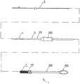
图1是本发明的结构示意图;Fig. 1 is the structural representation of the present invention;
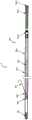
图2是本发明的定位器结构示意图;Fig. 2 is the structure schematic diagram of the locator of the present invention;
图3是本发明的定位器异型管的内腔结构示意图;Fig. 3 is the inner cavity structure schematic diagram of the positioner special-shaped tube of the present invention;
图4是本发明的J型定位钩结构示意图;4 is a schematic structural diagram of a J-shaped positioning hook of the present invention;
图5是本发明的可吸收插塞结构示意图。FIG. 5 is a schematic diagram of the structure of the absorbable plug of the present invention.
具体实施方式Detailed ways
下面将结合本发明的实施例,对本发明的技术方案进行清楚、完整地描述,显然,所描述的实施例仅仅是本发明一部分实施例,而不是全部的实施例。基于本发明中的实施例,本领域普通技术人员在没有作出创造性劳动前提下所获得的所有其他实施例,都属于本发明保护的范围。The technical solutions of the present invention will be clearly and completely described below with reference to the embodiments of the present invention. Obviously, the described embodiments are only a part of the embodiments of the present invention, rather than all the embodiments. Based on the embodiments of the present invention, all other embodiments obtained by those of ordinary skill in the art without creative efforts shall fall within the protection scope of the present invention.
根据图1-5所示,作为实施例,股动脉穿刺点封堵止血器,采用医用高分子材料制作,如聚氨酯或聚丙烯等材料。主要包括扩张管 1、鞘管2、推进器4、定位器5等零部件及可吸收插塞。扩张管及鞘管2为现有技术。扩张管1的内径与定位器5的外径紧密配合。定位器5定位在血管切口后,将鞘管2套在扩张管1上顺着定位器5插入肌肉穿刺通道至血管外壁。As shown in Figures 1-5, as an embodiment, the femoral artery puncture point blocking hemostatic device is made of medical polymer materials, such as polyurethane or polypropylene. It mainly includes parts such as dilation tube 1,
鞘管2包括薄壁管201和把手202,薄壁管201与把手202通过粘合等方式相连接。The
推进器设置推进管401、推送杆402、推送柄403等,推送管401 与推送杆402通过卡口连接,推送杆402可沿推送管401向前推动。推送杆402与推送柄403连接。可吸收插塞3存储在推送管401内部,当鞘管2定位后,推进器将可吸收插塞3沿鞘管2的把手202内腔推送至血管切开点上方、腱膜下方处。可吸收插塞选用可吸收降解的生物材料,如合成聚乙醇酸,吸血后具有良好的膨胀性能,进而压迫止血。合成聚乙醇酸为现有材料,再此不做赘述。在可吸收插塞3外套设记忆合金网311,记忆合金网采用镍钛合金管通过激光镂空雕刻而成。记忆合金网311的高度小于所述可吸收插塞3的高度。记忆合金网311的远端与可吸收插塞3的远端持平,当可吸收插塞3吸血时膨胀,记忆合金网311限制可吸收插塞3横向膨胀,使其倾向于纵向膨胀。从而压迫血管穿刺点,进而达到止血效果。同时避免可吸收插塞 3远端贴合血管穿刺点处位置,在横向膨胀时,带动血管穿刺点横向扩展,导致无法迅速闭合的问题。记忆合金网311的远端设置压翼 312,所述压翼312与所述记忆合金网311的夹角α为89°,角度过大易发生刺破血管的风险。压翼312表面设置胶原蛋白海绵层,在吸血时进行膨胀,从而压迫血管穿刺点周边血管壁,使血管穿刺点闭合更加紧密,从而进一步加快止血。可吸收插塞的近端设置环形合成聚乙醇酸加强筋313。增大膨胀量,提高更大的压力。The pusher is provided with a
定位器5主要包括软头501、连接管套502、金属丝503、J型定位钩504、异型管505、金属套管506。异型管505为可造影的聚氨酯硬管。内腔为矩形异型孔。前端设置有球形软头501,软头选用柔软、韧性好的高分子材料,如聚氨酯等。保证推送过程中不损伤血管内壁。异型管505一侧设置有测控5051,异型管505一端与金属套管506连接,金属套管506与金属丝503连接,金属丝503连接J型定位钩504,金属丝503及J型定位钩504选用镍钛合金。异型管505 内腔为矩形孔,矩形孔与矩形的连接套管502紧密配合。保证J型定位钩504与异型管505的轴向剖面同面,可防止J型定位钩504在异型管505内腔自由旋转。J型定位钩504的一端头为球形钝头,不损伤血管,在金属丝503的带动下,J型定位钩504移动并由测控5051 处伸出管外,与异型管505形成分叉,在手术中可准确钩挂在血管穿刺口。The
J型定位钩504由逐渐变细的直丝5041和弧形的端部5042及球形的端头5043构成。The J-shaped
金属套管506选用医用金属材料及高分子材料,包括外套管5061、内套管5062、手柄5063、色标标记5064。外套管5061内设置有内套管5062,构成双层金属套管506,内套管5062的一端设置手柄5063,另一端通过金属丝503与J型定位钩504连接。外套管5061与异型管505连接,把手5063带动内套管5062沿外套管5061滑行,内套管5062表面设置色标标记5064,当色标标记5064露出外套管5061 时,表明J型定位钩504完全从异型管505管体的侧孔5051处漏出。The
本发明的操作方法:介入术后,在拔出介入术所用鞘管2 (不包括在本器械中)前,将定位器5软头501沿鞘管2送入血管内一定程度后,然后固定定位器5外套管5061,拉出带有手柄5063的内套管5062,使标记5064露出,此时内套管5062带有镍钛合金的J 型定位钩504从聚氨酯(PU)异型管505的侧孔5051中伸出到血管中,然后整体拨动定位器5,伸出的捏钛合金定位钩504即可钩挂在血管穿刺口处,此时合金定位钩504可精确定位在血管刺口处;然后顺着定位器5和鞘管2,鞘管2的管头同样卡在镍钛合金的J型定位钩的位置,随后把内套管5062推入外套管5061中,J型定位钩504 即可退入到异型管505,撤除定位器5和扩张管1,仅留鞘管2于肌肉中;然后将推送器4安装到鞘管2的把手202内腔上,推动推送柄 403,存储在推进器4的储藏室401内部的可吸收插塞3沿鞘管2送至血管刺口外壁,可吸收插塞3吸水膨胀压迫血管和促进凝块形成,达到止血效果。The operation method of the present invention: after the intervention, before pulling out the sheath 2 (not included in the device) used for the intervention, the
以上所述,仅为本发明的具体实施方式,但本发明的保护范围并不局限于此,任何熟悉本技术领域的技术人员在本发明揭露的技术范围内,可轻易想到变化或替换,都应涵盖在本发明的保护范围之内。因此,本发明的保护范围应所述以权利要求的保护范围为准。The above are only specific embodiments of the present invention, but the protection scope of the present invention is not limited thereto. Any person skilled in the art can easily think of changes or substitutions within the technical scope disclosed by the present invention. should be included within the protection scope of the present invention. Therefore, the protection scope of the present invention should be based on the protection scope of the claims.
Claims (1)
Priority Applications (1)
| Application Number | Priority Date | Filing Date | Title |
|---|---|---|---|
| CN201810738095.5ACN109009300B (en) | 2018-07-06 | 2018-07-06 | Femoral artery puncture point plugging hemostat |
Applications Claiming Priority (1)
| Application Number | Priority Date | Filing Date | Title |
|---|---|---|---|
| CN201810738095.5ACN109009300B (en) | 2018-07-06 | 2018-07-06 | Femoral artery puncture point plugging hemostat |
Publications (2)
| Publication Number | Publication Date |
|---|---|
| CN109009300A CN109009300A (en) | 2018-12-18 |
| CN109009300Btrue CN109009300B (en) | 2020-08-14 |
Family
ID=64641696
Family Applications (1)
| Application Number | Title | Priority Date | Filing Date |
|---|---|---|---|
| CN201810738095.5AExpired - Fee RelatedCN109009300B (en) | 2018-07-06 | 2018-07-06 | Femoral artery puncture point plugging hemostat |
Country Status (1)
| Country | Link |
|---|---|
| CN (1) | CN109009300B (en) |
Family Cites Families (4)
| Publication number | Priority date | Publication date | Assignee | Title |
|---|---|---|---|---|
| US20080077178A1 (en)* | 1990-09-21 | 2008-03-27 | Datascope Investment Corp. | Device and method for sealing puncture wounds |
| US8083768B2 (en)* | 2000-12-14 | 2011-12-27 | Ensure Medical, Inc. | Vascular plug having composite construction |
| CN200970250Y (en)* | 2006-11-02 | 2007-11-07 | 北京乐普医疗器械有限公司 | Arterial puncture point blocking hemostat after coronary disease micro traumatic operation |
| US8764793B2 (en)* | 2011-06-17 | 2014-07-01 | Northwestern University | Left atrial appendage occluder |
- 2018
- 2018-07-06CNCN201810738095.5Apatent/CN109009300B/ennot_activeExpired - Fee Related
Also Published As
| Publication number | Publication date |
|---|---|
| CN109009300A (en) | 2018-12-18 |
Similar Documents
| Publication | Publication Date | Title |
|---|---|---|
| USRE34866E (en) | Device for sealing percutaneous puncture in a vessel | |
| US4890612A (en) | Device for sealing percutaneous puncture in a vessel | |
| US5192300A (en) | Insertion assembly and method of inserting a vessel plug into the body of a patient | |
| US5275616A (en) | Insertion assembly and method of inserting a vessel plug into the body of a patient | |
| US7875054B2 (en) | Connective tissue closure device and method | |
| US9254124B2 (en) | Self-orientating suture wound closure device | |
| US4744364A (en) | Device for sealing percutaneous puncture in a vessel | |
| US5906631A (en) | Method and device for sealing vascular puncture wounds | |
| CN104586460B (en) | A kind of vascular puncture plugging system | |
| CN107802311A (en) | A fully degradable vessel closure structure | |
| WO1992022252A1 (en) | Sealing device for a blood vessel or the like | |
| CA2122041A1 (en) | Plug device for sealing openings and method of use | |
| CN109528258B (en) | A vascular anastomosis support dilator | |
| CN113749719B (en) | Implant device with fishbone-shaped anchoring structure and delivery system thereof | |
| CN109009300B (en) | Femoral artery puncture point plugging hemostat | |
| JP5863717B2 (en) | Amniotic membrane insertion device | |
| CN108938036A (en) | A kind of injecting glue closure left auricle of heart device of the front end with closure sacculus | |
| CN116983027A (en) | Vascular closure device | |
| CN108926366B (en) | Rubber injection plugging left auricle device with nickel-titanium alloy mesh cover at front end | |
| CN216876482U (en) | Vascular occluder | |
| CN105433990B (en) | A kind of human pathology or doctor's source chamber road locking device | |
| CN116407183A (en) | apical closure system | |
| CN222676310U (en) | Vascular suture device | |
| CN216985004U (en) | Suture type severed finger replantation vein micro-support | |
| CN209360811U (en) | A kind of vascular thrombosis takes bolt device |
Legal Events
| Date | Code | Title | Description |
|---|---|---|---|
| PB01 | Publication | ||
| PB01 | Publication | ||
| SE01 | Entry into force of request for substantive examination | ||
| SE01 | Entry into force of request for substantive examination | ||
| GR01 | Patent grant | ||
| GR01 | Patent grant | ||
| CF01 | Termination of patent right due to non-payment of annual fee | ||
| CF01 | Termination of patent right due to non-payment of annual fee | Granted publication date:20200814 Termination date:20210706 |