CN108883239B - Device for the inhalation-synchronized dispensing of a fluid product - Google Patents
Device for the inhalation-synchronized dispensing of a fluid productDownload PDFInfo
- Publication number
- CN108883239B CN108883239BCN201780020161.9ACN201780020161ACN108883239BCN 108883239 BCN108883239 BCN 108883239BCN 201780020161 ACN201780020161 ACN 201780020161ACN 108883239 BCN108883239 BCN 108883239B
- Authority
- CN
- China
- Prior art keywords
- container
- inhalation
- actuated position
- fluid
- actuated
- Prior art date
- Legal status (The legal status is an assumption and is not a legal conclusion. Google has not performed a legal analysis and makes no representation as to the accuracy of the status listed.)
- Active
Links
Images


Classifications
- A—HUMAN NECESSITIES
- A61—MEDICAL OR VETERINARY SCIENCE; HYGIENE
- A61M—DEVICES FOR INTRODUCING MEDIA INTO, OR ONTO, THE BODY; DEVICES FOR TRANSDUCING BODY MEDIA OR FOR TAKING MEDIA FROM THE BODY; DEVICES FOR PRODUCING OR ENDING SLEEP OR STUPOR
- A61M15/00—Inhalators
- A61M15/0091—Inhalators mechanically breath-triggered
- A61M15/0095—Preventing manual activation in absence of inhalation
- A—HUMAN NECESSITIES
- A61—MEDICAL OR VETERINARY SCIENCE; HYGIENE
- A61M—DEVICES FOR INTRODUCING MEDIA INTO, OR ONTO, THE BODY; DEVICES FOR TRANSDUCING BODY MEDIA OR FOR TAKING MEDIA FROM THE BODY; DEVICES FOR PRODUCING OR ENDING SLEEP OR STUPOR
- A61M15/00—Inhalators
- A61M15/0001—Details of inhalators; Constructional features thereof
- A61M15/0021—Mouthpieces therefor
- A—HUMAN NECESSITIES
- A61—MEDICAL OR VETERINARY SCIENCE; HYGIENE
- A61M—DEVICES FOR INTRODUCING MEDIA INTO, OR ONTO, THE BODY; DEVICES FOR TRANSDUCING BODY MEDIA OR FOR TAKING MEDIA FROM THE BODY; DEVICES FOR PRODUCING OR ENDING SLEEP OR STUPOR
- A61M15/00—Inhalators
- A61M15/0065—Inhalators with dosage or measuring devices
- A61M15/0068—Indicating or counting the number of dispensed doses or of remaining doses
- A61M15/008—Electronic counters
- A—HUMAN NECESSITIES
- A61—MEDICAL OR VETERINARY SCIENCE; HYGIENE
- A61M—DEVICES FOR INTRODUCING MEDIA INTO, OR ONTO, THE BODY; DEVICES FOR TRANSDUCING BODY MEDIA OR FOR TAKING MEDIA FROM THE BODY; DEVICES FOR PRODUCING OR ENDING SLEEP OR STUPOR
- A61M15/00—Inhalators
- A61M15/009—Inhalators using medicine packages with incorporated spraying means, e.g. aerosol cans
- A—HUMAN NECESSITIES
- A61—MEDICAL OR VETERINARY SCIENCE; HYGIENE
- A61M—DEVICES FOR INTRODUCING MEDIA INTO, OR ONTO, THE BODY; DEVICES FOR TRANSDUCING BODY MEDIA OR FOR TAKING MEDIA FROM THE BODY; DEVICES FOR PRODUCING OR ENDING SLEEP OR STUPOR
- A61M15/00—Inhalators
- A61M15/0001—Details of inhalators; Constructional features thereof
- A61M15/0021—Mouthpieces therefor
- A61M15/0025—Mouthpieces therefor with caps
- A—HUMAN NECESSITIES
- A61—MEDICAL OR VETERINARY SCIENCE; HYGIENE
- A61M—DEVICES FOR INTRODUCING MEDIA INTO, OR ONTO, THE BODY; DEVICES FOR TRANSDUCING BODY MEDIA OR FOR TAKING MEDIA FROM THE BODY; DEVICES FOR PRODUCING OR ENDING SLEEP OR STUPOR
- A61M16/00—Devices for influencing the respiratory system of patients by gas treatment, e.g. ventilators; Tracheal tubes
- A61M16/0003—Accessories therefor, e.g. sensors, vibrators, negative pressure
- A61M2016/0015—Accessories therefor, e.g. sensors, vibrators, negative pressure inhalation detectors
- A61M2016/0018—Accessories therefor, e.g. sensors, vibrators, negative pressure inhalation detectors electrical
- A61M2016/0021—Accessories therefor, e.g. sensors, vibrators, negative pressure inhalation detectors electrical with a proportional output signal, e.g. from a thermistor
- A—HUMAN NECESSITIES
- A61—MEDICAL OR VETERINARY SCIENCE; HYGIENE
- A61M—DEVICES FOR INTRODUCING MEDIA INTO, OR ONTO, THE BODY; DEVICES FOR TRANSDUCING BODY MEDIA OR FOR TAKING MEDIA FROM THE BODY; DEVICES FOR PRODUCING OR ENDING SLEEP OR STUPOR
- A61M2205/00—General characteristics of the apparatus
- A61M2205/27—General characteristics of the apparatus preventing use
- A61M2205/276—General characteristics of the apparatus preventing use preventing unwanted use
- A—HUMAN NECESSITIES
- A61—MEDICAL OR VETERINARY SCIENCE; HYGIENE
- A61M—DEVICES FOR INTRODUCING MEDIA INTO, OR ONTO, THE BODY; DEVICES FOR TRANSDUCING BODY MEDIA OR FOR TAKING MEDIA FROM THE BODY; DEVICES FOR PRODUCING OR ENDING SLEEP OR STUPOR
- A61M2205/00—General characteristics of the apparatus
- A61M2205/33—Controlling, regulating or measuring
- A61M2205/3331—Pressure; Flow
- A—HUMAN NECESSITIES
- A61—MEDICAL OR VETERINARY SCIENCE; HYGIENE
- A61M—DEVICES FOR INTRODUCING MEDIA INTO, OR ONTO, THE BODY; DEVICES FOR TRANSDUCING BODY MEDIA OR FOR TAKING MEDIA FROM THE BODY; DEVICES FOR PRODUCING OR ENDING SLEEP OR STUPOR
- A61M2205/00—General characteristics of the apparatus
- A61M2205/35—Communication
- A61M2205/3546—Range
- A61M2205/3553—Range remote, e.g. between patient's home and doctor's office
- A—HUMAN NECESSITIES
- A61—MEDICAL OR VETERINARY SCIENCE; HYGIENE
- A61M—DEVICES FOR INTRODUCING MEDIA INTO, OR ONTO, THE BODY; DEVICES FOR TRANSDUCING BODY MEDIA OR FOR TAKING MEDIA FROM THE BODY; DEVICES FOR PRODUCING OR ENDING SLEEP OR STUPOR
- A61M2205/00—General characteristics of the apparatus
- A61M2205/35—Communication
- A61M2205/3546—Range
- A61M2205/3561—Range local, e.g. within room or hospital
- A—HUMAN NECESSITIES
- A61—MEDICAL OR VETERINARY SCIENCE; HYGIENE
- A61M—DEVICES FOR INTRODUCING MEDIA INTO, OR ONTO, THE BODY; DEVICES FOR TRANSDUCING BODY MEDIA OR FOR TAKING MEDIA FROM THE BODY; DEVICES FOR PRODUCING OR ENDING SLEEP OR STUPOR
- A61M2205/00—General characteristics of the apparatus
- A61M2205/35—Communication
- A61M2205/3576—Communication with non implanted data transmission devices, e.g. using external transmitter or receiver
- A61M2205/3584—Communication with non implanted data transmission devices, e.g. using external transmitter or receiver using modem, internet or bluetooth
- A—HUMAN NECESSITIES
- A61—MEDICAL OR VETERINARY SCIENCE; HYGIENE
- A61M—DEVICES FOR INTRODUCING MEDIA INTO, OR ONTO, THE BODY; DEVICES FOR TRANSDUCING BODY MEDIA OR FOR TAKING MEDIA FROM THE BODY; DEVICES FOR PRODUCING OR ENDING SLEEP OR STUPOR
- A61M2205/00—General characteristics of the apparatus
- A61M2205/35—Communication
- A61M2205/3576—Communication with non implanted data transmission devices, e.g. using external transmitter or receiver
- A61M2205/3592—Communication with non implanted data transmission devices, e.g. using external transmitter or receiver using telemetric means, e.g. radio or optical transmission
- A—HUMAN NECESSITIES
- A61—MEDICAL OR VETERINARY SCIENCE; HYGIENE
- A61M—DEVICES FOR INTRODUCING MEDIA INTO, OR ONTO, THE BODY; DEVICES FOR TRANSDUCING BODY MEDIA OR FOR TAKING MEDIA FROM THE BODY; DEVICES FOR PRODUCING OR ENDING SLEEP OR STUPOR
- A61M2205/00—General characteristics of the apparatus
- A61M2205/50—General characteristics of the apparatus with microprocessors or computers
- A61M2205/502—User interfaces, e.g. screens or keyboards
- A—HUMAN NECESSITIES
- A61—MEDICAL OR VETERINARY SCIENCE; HYGIENE
- A61M—DEVICES FOR INTRODUCING MEDIA INTO, OR ONTO, THE BODY; DEVICES FOR TRANSDUCING BODY MEDIA OR FOR TAKING MEDIA FROM THE BODY; DEVICES FOR PRODUCING OR ENDING SLEEP OR STUPOR
- A61M2205/00—General characteristics of the apparatus
- A61M2205/50—General characteristics of the apparatus with microprocessors or computers
- A61M2205/52—General characteristics of the apparatus with microprocessors or computers with memories providing a history of measured variating parameters of apparatus or patient
Landscapes
- Health & Medical Sciences (AREA)
- Engineering & Computer Science (AREA)
- Life Sciences & Earth Sciences (AREA)
- Anesthesiology (AREA)
- Pulmonology (AREA)
- Biomedical Technology (AREA)
- Heart & Thoracic Surgery (AREA)
- Hematology (AREA)
- Bioinformatics & Cheminformatics (AREA)
- Animal Behavior & Ethology (AREA)
- General Health & Medical Sciences (AREA)
- Public Health (AREA)
- Veterinary Medicine (AREA)
- Biophysics (AREA)
- Containers And Packaging Bodies Having A Special Means To Remove Contents (AREA)
- Nozzles (AREA)
Abstract
Translated fromChinese
Description
Translated fromChinese技术领域technical field
本发明涉及一种流体分配器设备,其中分配与吸入同步,更具体地,本发明涉及与吸入同步的气溶胶型吸入器设备。The present invention relates to a fluid dispenser device wherein dispensing is synchronized with inhalation, and more particularly, the present invention relates to an aerosol-type inhaler device synchronized with inhalation.
背景技术Background technique
呼吸致动吸入器(Breath actuated inhaler,BAI)设备在现有技术中是众所周知的。这种类型的设备的主要优点在于流体的分配与患者吸入同步,以便保证适当地将流体分配到气道中。因而,在气溶胶设备领域,即在借助于推进剂气体分配流体的设备的领域中,已经提出了许多类型的呼吸致动吸入器设备。然而,这些设备存在包括大量部件的缺点,即它们的制造和组装复杂且昂贵,这显然是不利的。在致动阈值不太高的情况下,还难以在对每次吸入的可靠触发与足够坚固以防止意外的多余致动的闩锁之间找到适当的平衡。不幸的是,当闩锁意外释放时,即使用户不想要,设备也会自动致动并分配剂量。Breath actuated inhaler (BAI) devices are well known in the art. The main advantage of this type of device is that the distribution of fluid is synchronized with patient inhalation in order to ensure proper distribution of fluid into the airway. Thus, in the field of aerosol devices, ie in the field of devices for dispensing fluids by means of propellant gas, many types of breath-actuated inhaler devices have been proposed. However, these devices have the disadvantage of comprising a large number of parts, ie their manufacture and assembly are complex and expensive, which is obviously disadvantageous. It is also difficult to find the right balance between a reliable trigger for each inhalation and a latch that is strong enough to prevent accidental unwanted actuation without the actuation threshold being too high. Unfortunately, when the latch is accidentally released, the device automatically actuates and dispenses the dose, even if the user does not want it.
因而,为了适当地分配剂量,比自动致动设备更重要的是,即使致动或触发保持手动,也要使分配与用户吸入同步。Thus, in order to properly dispense a dose, it is more important than an automatically actuated device to synchronize the dispensing with the user's inhalation, even if the actuation or triggering remains manual.
文献FR2775668描述了现有技术的设备。Document FR2775668 describes a prior art device.
发明内容SUMMARY OF THE INVENTION
本发明的一个目的是提供一种不具有上述缺点的吸入同步的流体分配器设备。It is an object of the present invention to provide a suction-synchronized fluid dispenser device that does not have the above-mentioned disadvantages.
本发明的另一目的是提供一种吸入同步的流体分配器设备,该设备通过保证在每次吸入时的有效致动来改善操作可靠性。Another object of the present invention is to provide an inhalation synchronised fluid dispenser device which improves operational reliability by ensuring efficient actuation at each inhalation.
本发明的另一目的是提供一种吸入同步的流体分配器设备,该设备使意外或不需要的致动的风险最小化。Another object of the present invention is to provide a suction synchronized fluid dispenser device that minimizes the risk of accidental or unwanted actuation.
本发明的另一目的是提供一种吸入同步的流体分配器设备,该设备不具有过高的致动阈值,从而使得相对较弱的人,诸如病人或老人,可以以安全可靠的方式使用该设备。Another object of the present invention is to provide an inhalation synchronized fluid dispenser device that does not have an excessively high actuation threshold, thereby allowing relatively weak persons, such as the sick or the elderly, to use the device in a safe and secure manner equipment.
本发明的另一目的是提供一种吸入同步的流体分配器设备,该设备的制造和组装简单且便宜。Another object of the present invention is to provide a suction synchronized fluid dispenser device which is simple and inexpensive to manufacture and assemble.
因此,本申请提供一种吸入同步的流体分配器设备,该设备包括主体,主体设置有嘴部件、流体容器、以及计量阀,该流体容器容纳流体和推进剂气体,并被安装为在所述主体中轴向滑动,计量阀包括阀构件,并组装在容器上,以选择性地分配流体,所述设备还包括:Accordingly, the present application provides a suction-synchronized fluid dispenser device comprising a body provided with a mouthpiece, a fluid container, and a metering valve, the fluid container containing fluid and propellant gas, and mounted to be in said Sliding axially in the body, the metering valve includes a valve member and is assembled on the container to selectively dispense fluid, the apparatus further comprising:
致动器元件,该致动器元件能够在所述计量阀无法被致动的非致动位置与所述计量阀能够被致动的致动位置之间移动和/或变形;以及an actuator element movable and/or deformable between a non-actuated position in which the metering valve cannot be actuated and an actuated position in which the metering valve can be actuated; and
吸入控制触发器系统,该吸入控制触发器系统包括能够在吸入的作用下变形和/或移动的吸入敏感构件,当所述吸入敏感构件变形和/或移动时,使所述致动器元件从其非致动位置朝向其致动位置移动和/或变形,所述致动器元件是阻挡元件,该阻挡元件在非致动位置首先与主体协作,并随后与容器协作,以防止所述容器在主体中轴向移动。An inhalation control trigger system comprising an inhalation sensitive member capable of deforming and/or moving under the action of inhalation, when said inhalation sensitive member is deformed and/or moved, causing said actuator element from its non-actuated position is moved and/or deformed towards its actuated position, said actuator element being a blocking element which in the non-actuated position cooperates first with the body and then with the container to prevent said container Axial movement in the body.
有利地,所述致动器元件是阻挡环,阻挡环固定在容器上,并且包括至少一个轴向凸片,该至少一个轴向凸片与固定至所述主体的肩部协作,以防止所述容器在主体中轴向移动,其中阻挡环具体地卡扣固定在容器上,该至少一个轴向凸片具体为三个轴向凸片。Advantageously, said actuator element is a blocking ring fixed to the container and comprising at least one axial tab cooperating with a shoulder fixed to said body to prevent any The container moves axially in the main body, wherein the blocking ring is specifically snap-fastened on the container, and the at least one axial tab is in particular three axial tabs.
有利地,所述至少一个轴向凸片能够径向向外变形,以从非致动位置朝向致动位置通过,触发器元件被设置为将所述至少一个轴向凸片保持在非致动位置。Advantageously, the at least one axial tab is deformable radially outwards to pass from the non-actuated position towards the actuated position, the trigger element being arranged to retain the at least one axial tab in the non-actuated position Location.
有利地,所述触发器元件被安装为在阻挡位置与释放位置之间移动,在阻挡位置,触发器元件将所述阻挡环阻挡于其非致动位置,在释放位置,触发器元件不阻挡所述阻挡环。Advantageously, the trigger element is mounted to move between a blocking position, in which the trigger element blocks the blocking ring in its non-actuated position, and a release position, in which the trigger element does not block the blocking ring.
有利地,所述吸入控制触发器系统包括可变形膜,可变形膜限定可变形气室,所述可变形膜固定到所述触发器元件,所述可变形膜在吸入期间变形,从而使所述触发器元件从其阻挡位置朝向其释放位置移动。Advantageously, said inhalation control trigger system comprises a deformable membrane defining a deformable air chamber, said deformable membrane being fixed to said trigger element, said deformable membrane deforming during inhalation such that all The trigger element is moved from its blocking position towards its releasing position.
有利地,所述触发器元件能够由用户通过主体中的至少一个开口接近,使得即使在没有吸入的情况下也能够手动地使触发器元件朝向其释放位置移动。Advantageously, the trigger element is accessible by the user through at least one opening in the body, so that the trigger element can be manually moved towards its release position even without inhalation.
有利地,所述阻挡元件包括轴向延伸部,该轴向延伸部具有相对于所述主体径向和轴向固定的底端、以及在非致动位置与所述容器配合的顶端。Advantageously, the blocking element comprises an axial extension having a bottom end radially and axially fixed with respect to the body, and a top end cooperating with the container in a non-actuated position.
有利地,所述吸入控制触发器系统包括活塞,活塞在腔室中在静止位置与吸入位置之间滑动。Advantageously, the inhalation control trigger system comprises a piston sliding in the chamber between a rest position and an inhalation position.
有利地,所述阻挡元件组装在杆上,该杆固定至活塞,使得在吸入期间,所述杆径向移动,从而使所述轴向延伸部朝向其致动位置变形和/或移动。Advantageously, the blocking element is assembled on a rod, which is fixed to the piston, such that during inhalation, the rod moves radially, thereby deforming and/or moving the axial extension towards its actuated position.
有利地,所述设备包括电子剂量计数器。Advantageously, the device comprises an electronic dose counter.
有利地,所述设备包括信号发射器装置,信号发射器装置用于对与该设备的致动有关的信息进行通信,具体为远程通信。Advantageously, the device comprises signal transmitter means for communicating, in particular telecommunication, information related to the actuation of the device.
附图说明Description of drawings
参考附图,通过下面由非限制性示例给出的详细描述,这些特征和优点以及其他方面会变得更加清晰,在附图中:These features and advantages, as well as other aspects, will become more apparent from the following detailed description, given by non-limiting examples, with reference to the accompanying drawings, in which:
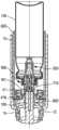
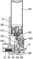
图1是第一有利实施方式中处于静止位置的流体分配器设备的示意性剖视图;Figure 1 is a schematic cross-sectional view of a fluid dispenser device in a rest position in a first advantageous embodiment;
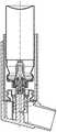
图2是与图1中的视图类似的、处于另一竖直剖面中的视图;Figure 2 is a view in another vertical section similar to the view in Figure 1;
图3是与图1中的视图类似的、处于抽吸前的非分配位置的视图;Figure 3 is a view similar to the view in Figure 1 in a non-dispensing position prior to aspiration;
图4是与图3中的视图类似的、处于抽吸后的位置的视图;Figure 4 is a view similar to the view in Figure 3, in a position after suction;
图5是与图2中的视图类似的、处于用于分配一定剂量流体的位置的视图;Figure 5 is a view similar to the view in Figure 2, in a position for dispensing a dose of fluid;
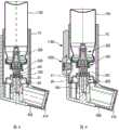
图6是与图5中的视图类似的、处于另一竖直剖面中的视图;Figure 6 is a view similar to the view in Figure 5 in another vertical section;
图7是与图6中的视图类似的、处于分配一定剂量流体之后的位置的视图;Figure 7 is a view similar to the view in Figure 6, in a position after dispensing a dose of fluid;
图8是处于静止位置的气室的变型实施方式的示意性剖视图;Figure 8 is a schematic cross-sectional view of a variant embodiment of the plenum in a rest position;
图9是与图8中的视图类似的、示出了处于静止位置的包括电子器件的另一变型实施方式的视图;FIG. 9 is a view similar to the view in FIG. 8 showing another variant embodiment including electronics in a rest position;
图10是图1的主体的示意性立体细节图;Figure 10 is a schematic perspective detail view of the body of Figure 1;
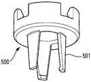
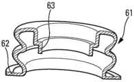
图11是图1的阻挡环的示意性立体细节图;Figure 11 is a schematic perspective detail view of the blocking ring of Figure 1;
图12是图1的触发元件的示意性立体细节图;Figure 12 is a schematic perspective detail view of the trigger element of Figure 1;
图13是图1可变形膜的示意性剖视立体详细视图;Figure 13 is a schematic cross-sectional perspective detail view of the deformable membrane of Figure 1;
图14是处于静止位置的又一有利实施方式中的流体分配器设备的示意性剖视图;14 is a schematic cross-sectional view of a fluid dispenser apparatus in yet another advantageous embodiment in a rest position;
图15是与图14中的视图类似的、处于分配位置的视图;以及Fig. 15 is a view similar to the view in Fig. 14 in a dispensing position; and
图16是与图14中的视图类似的、示出变型实施方式的视图。FIG. 16 is a view similar to the view in FIG. 14 showing a modified embodiment.
具体实施方式Detailed ways
在说明书中,术语“顶部”、“底部”、“向上”和“向下”指的是图1中具体示出的设备的直立位置。术语“轴向”和“径向”是相对于图1中具体示出的竖直中心轴线A。术语“近侧”和“远侧”是相对于嘴部件。In the description, the terms "top", "bottom", "upward" and "downward" refer to the upright position of the device specifically shown in FIG. 1 . The terms "axial" and "radial" are relative to the vertical central axis A specifically shown in FIG. 1 . The terms "proximal" and "distal" are relative to the mouthpiece.
更具体地,本发明适于如下面更详细地描述的、用于口腔分配的气溶胶阀型的吸入器设备,但是本发明也可适于其它类型的吸入器设备,例如,鼻型吸入器设备。More particularly, the present invention is suitable for an inhaler device of the aerosol valve type for oral dispensing, as described in more detail below, but the present invention may also be suitable for other types of inhaler devices, eg, nasal-type inhalers equipment.
附图示出了本发明的若干有利实施方式,但是,自然地,下面描述的部件中的一个或多个在提供相似或相同功能的情况下可以以某些其他方式来制造。The drawings illustrate several advantageous embodiments of the invention, but naturally, one or more of the components described below can be manufactured in some other way while providing similar or identical functions.
参考附图,该设备包括设置有嘴部件400的主体10。嘴部件400限定分配器孔,当该设备被使用时,使用者通过该分配器孔吸入。可移除的保护帽410可设置在嘴部件400上,具体地,在该设备被存储时,使用者在使用之前移除该保护帽410。图1、图8和图9示出了可以是任何形状的这种保护帽。Referring to the figures, the device includes a
主体10容纳含有待分配流体和推进剂气体的容器100和计量阀200,其中,推进剂气体诸如为氢氟烷烃(HFA)型气体,计量阀200安装在容器100上,以选择性地分配流体。计量阀200包括阀体201和阀构件210,阀构件210在致动期间可相对于阀体201轴向移动,并因而相对于所述容器100轴向移动。计量阀200可为任何合适类型。计量阀200可通过紧固件元件固定至容器100,其中,优选地,在其间插设有颈部垫圈4,紧固件元件优选为卷边盖5。The
有利地,在致动期间,阀构件210相对于主体10静止,以及容器100相对于主体10在远侧位置与近侧位置之间轴向移动,其中远侧位置即为静止位置。Advantageously, during actuation, the
所述计量阀200的阀构件210的出口孔经由通道300连接至嘴部件400,使用者通过嘴部件400吸入待分配的流体。通过已知的方式,所述阀构件210容纳在阀门井700中,阀门井700至少部分地限定所述通道300。在图1至图9的实施方式中,阀门井与主体10整体形成,而在图14至图16的实施方式中,所述阀门井可相对于主体10轴向移动。The outlet orifice of the
在本发明中,该设备包括致动器元件500、500',致动器元件500、500'可在非致动位置和致动位置之间移动和/或变形,其中,在非致动位置,所述计量阀200不能被致动,在致动位置,计量阀200可被致动。在静止位置,所述致动器元件500、500'处于非致动位置,并且使用者通过嘴部件400吸入,使得致动器元件500、500'朝向其致动位置移动和/或变形。换言之,只要使用者不吸入,就无法致动计量阀200,以及只有当使用者吸入时,才能致动计量阀200,有利地,通过手动按压容器100的底部来致动计量阀200。In the present invention, the device comprises an
如下面更详细的描述,致动器元件是阻挡元件500、500',阻挡元件500、500'在非致动位置防止容器100在主体10中轴向移动。在吸入期间,阻挡元件500、500'移动和/或变形,使得阻挡元件500、500'不再防止容器100在主体10中进行轴向移动。因而,在吸入之后,容器100的这种轴向移动导致计量阀200被致动,并且与吸入同步地分配一定剂量的流体。As described in more detail below, the actuator elements are blocking
因而,在没有吸入的情况下,不存在由意外或不完全致动导致活性剂量的流体损失的风险,其中,在意外或不完全致动期间,使用者不吸入。因而,仅当使用者吸入并同时按压容器100以便致动阀200时,才能致动阀200,并排出一定剂量的流体。Thus, without inhalation, there is no risk of fluid loss of the active dose resulting from accidental or incomplete actuation, during which the user does not inhale. Thus, only when the user inhales and simultaneously depresses the
该设备包括的触发器系统,该触发器系统由用户吸入控制,并且当用户通过嘴部件400吸入时,该触发器系统用于使致动器元件500、500'从其非致动位置朝向其致动位置移动和/或变形。The device includes a trigger system that is controlled by the user for inhalation and that serves to cause the
触发器系统包括在吸入的作用下可变形和/或可移动的吸入敏感构件60、65,吸入敏感构件60、65适于在其变形和/或移动时,使所述致动器元件500、500'从其非致动位置朝向其致动位置移动和/或变形。The trigger system comprises inhalation
如下面更详细描述的那样,吸入敏感构件可以制成可变形气室60的形式,例如,风箱或可变形袋。As described in more detail below, the inhalation sensitive member may be made in the form of a
在一个变型中,如参考图14至图16所述,吸入敏感构件可制成活塞65的形式,活塞65优选为圆柱形,并且在腔室66中滑动,腔室66优选为圆柱形,并且不可变形。In a variant, as described with reference to Figures 14 to 16, the inhalation sensitive member may be made in the form of a
在图1至图13所示的第一实施方式中,非致动位置对应于容器100在主体10中被阻挡的位置。在该阻挡位置,通过仅在吸入时释放的所述致动器元件来防止容器100移动。In the first embodiment shown in FIGS. 1 to 13 , the non-actuated position corresponds to the position in which the
主体10具体在图10中示出。当然,所示的这种形状不是限制性的。The
在该实施方式中,形成阻挡元件的致动器元件有利地由阻挡环500形成,阻挡环500包括至少一个可径向向外弹性变形的轴向阻挡凸片501,阻挡环500优选地包括三个轴向阻挡凸片501。图11是阻挡环500的立体图。阻挡环500固定在容器100上,盖5将计量阀200固定在容器100上,其中阻挡环500具体地卡扣固定在容器100上,阻挡环500具体地固定在盖5上。在静止位置,所述阻挡凸片501抵靠所述阀门井700的径向肩部710。该肩部优选地向下并径向向外倾斜,使得当容器100在致动期间在主体10中轴向滑动时,所述轴向阻挡凸片501在所述倾斜肩部710之上滑动,从而使轴向阻挡凸片501径向向外变形。In this embodiment, the actuator element forming the blocking element is advantageously formed by a blocking
触发器元件600安装在所述阀门井700周围,以在阻挡位置和释放位置之间轴向滑动,在阻挡位置,触发器元件600将阻挡环500阻挡在其非致动位置,在释放位置,触发器元件600不再阻挡所述阻挡环500。具体地,在图1至图13中的实施方式中,所述触发器元件600在阻挡位置与所述阻挡凸片501协作,从而防止所述阻挡凸片501径向向外的任何变形。因而,当所述触发元件600位于阻挡位置时,其防止所述阻挡凸片501径向向外变形,因此阻挡凸片保持由阀门井700的肩部710轴向阻挡,从而防止容器100轴向移动,并且防止致动计量阀200。可选地,可在阀门井700与触发器元件600之间插入诸如球的滑动装置,以便使所述触发器元件在吸入期间更易于滑动。
如在图12中可更具体地看到的是,触发器元件600有利地包括围绕阀门井700的、可轴向滑动的中空中心套管650,以及两个轴向凸片660,这两个轴向凸片径向相对,并且轴向凸片660中的每个均经由相应的径向间隔件670连接至中心套管650。轴向凸片660中的每个均与主体10的相应开口13协作,用于在阻挡位置基本上闭合开口13,以及在释放位置基本上打开开口13。由于开口13在吸入开始时是关闭的,因而,由吸入引起的吸入流最初主要传向触发器系统,在本实施方式中为可变形气室60。这使得可通过吸入来优化这种触发。当触发器元件600在吸入的作用下朝向其释放位置轴向移动时,并因而当使用者可致动计量阀200以便分配一定剂量的流体时,轴向凸片660打开所述主体10的开口13,而这会抽吸空气,因而增加吸入流。这优化了使用者吸入与分配剂量之间的同步,并且还促进将该剂量良好分配至使用者肺部。As can be seen in more detail in Figure 12, the
有利地,所述轴向凸片660可通过所述开口13从外部接近。这使得在需要的情况下能够手动地移动触发器元件600,从而即使不吸入,也能够致动计量阀200,例如,当需要接受该剂量流体的人不能充分吸入时。因而,这是一种安全措施。在该安全措施的变型中,可提供轴向延伸部(未示出),该轴向延伸部固定至触发器元件600,例如,从容器100侧向延伸,并且可由使用者从主体10的外部接近。Advantageously, said
有利地,并且在图2中可见,所述轴向凸片660与主体10的第一肩部14协作,以便通过形成防止所述触发器元件600上升超过阻挡位置的轴向抵接部来限定触发器元件600的阻挡位置。同样地,并且在图5中可见,所述轴向凸片660与主体10的第二肩部15协作,以通过形成防止所述触发器元件600向下移动超过释放位置的轴向抵接部来限定触发器元件600的释放位置。Advantageously, and as can be seen in FIG. 2 , said
在一个变型(未示出)中,触发器元件600不需要包括轴向凸片660,因而主体会不包括开口13。在这种配置中,吸入流可在主体内围绕阀门井轴向流动,该流动可通过设置有轴向切口以使空气流通过的中心套管650来促进。In a variant (not shown), the
在图1至图13的实施方式中,吸入敏感构件60以可变形气室的形式制成。有利地,气室包括可变形膜61,可变形膜61首先连接到主体10,并随后连接到所述触发器元件600。有利地,如图1至图9所示,膜载体套筒800以固定方式布置在主体10中,并具有底肩部810,底肩部810将膜61的第一边缘62压在主体10的部分17上。膜61的第二边缘63可固定在触发器元件600的通道630中,通道630有利地在所述触发器元件的中空中心套管650中形成。图13是波纹管形式的膜的剖视图,但是其他形式也是可能的,具体为仅袋或膜片,如图8所示。In the embodiment of Figures 1 to 13, the inhalation
在吸入期间,可变形膜61在由吸入产生的抽吸的作用下变形和/或收缩,从而使触发器元件600从其阻挡位置朝向其释放位置移动。然后,这使得所述阻挡凸片501能够变形,并因此使得形成致动器元件的所述阻挡环500能够从其非致动位置朝向其致动位置移动。图1至图7示出了以波纹管形式制成的可变形膜61,以及图8示出了一个变型,在该变型中,可变形膜以袋或膜片的形式制成。当然,也可设想其他形式。During inhalation, the
因而,阀200仅在吸入时被致动,使得该剂量的流体在吸入的同时被排出分配器孔。Thus, the
当使用者希望使用该设备时,使用者将嘴部件400放入口中,并手动按压容器100的底部,即,处于图中位置的所述容器100的顶部表面。然后,通过阻挡环500的阻挡凸片501,阻挡并防止容器100在主体10中滑动,阻挡凸片抵靠阀门井700的肩部710。可选地,容器100在被阻挡之前可执行短行程d1,然而,该初始小行程d1不足以致动计量阀200。图1示出了处于静止状态的设备,图3示出了在所述容器已进行初始小行程d1之后处于容器100被阻挡位置的设备。When the user wishes to use the device, the user places the
当使用者通过嘴部件400吸入时,可变形膜61变形,这使得固定在所述可变形膜61上的触发器元件600滑动,如图4所示。触发器元件600在阀门井700上方的运动径向地释放阻挡环500的凸片501。在由按压容器100的底部的使用者产生并通过容器100传递的轴向力的作用下,轴向凸片501能够径向向外变形,并因而越过肩部710,从而使容器100能够朝向其分配位置滑动,从而致动阀200。该分配位置如图5和图6所示。When the user inhales through the
在吸入结束时,触发器元件600通过膜61的弹性向上返回。图7示出了触发器元件600已经通过膜61返回但在用户释放施加在容器100上的压力之前的位置。At the end of the inhalation, the
当使用者释放容器100底部上的压力时,所述容器在阀200的复位弹簧的作用下朝着静止位置返回,以及计量阀的阀构件210同时返回到静止位置,从而再次用新剂量的流体填充阀室。因而,该设备准备好用于另一次使用。When the user releases the pressure on the bottom of the
图9示出了图8的实施方式的、承载电子模块的变型实施方式。FIG. 9 shows a variant embodiment of the embodiment of FIG. 8 carrying an electronic module.
具体地,提供电子剂量计数器1000,电子剂量计数器1000有利地组装在主体10上。具体地,计数器100可例如通过接触传感器来检测容器100的运动。在变型中,计数器1000可连接到传感器,具体是膜传感器,该传感器检测例如在阀门井700中正被分配的流体的剂量。电子计数器1000可通过其他方式致动,例如,通过检测计量阀的阀构件210相对于阀体201的运动。Specifically, an
优选地,该设备还包括信号发射器装置1100,以对与设备的致动有关的信息进行通信,具体为远程通信。具体地,主体10可包括信号发射器模块,以与任何基站远程通信。有利地提供适当的电源装置。Preferably, the device further comprises signal transmitter means 1100 to communicate information related to the actuation of the device, in particular telecommunication. Specifically, the
具体地,电子模块可有利地包括卡,该卡包括发送脉冲的电开关。该模块还可包括显示器和/或使用蓝牙或Wifi连接,以向附带的外围设备发送信息。可提供合适的传感器,诸如流量传感器和/或压力传感器,以检测吸入流的各种参数。In particular, the electronic module may advantageously comprise a card comprising electrical switches that transmit pulses. The module may also include a display and/or use a Bluetooth or Wifi connection to send information to attached peripherals. Suitable sensors, such as flow sensors and/or pressure sensors, may be provided to detect various parameters of the suction flow.
通过与对实际分配的每份剂量进行计数的剂量计数器1000相关联,以及与本发明的吸入同步设备相关联,信号发射器装置1100使得能够以完全可靠的方式传送已分配的每份剂量,例如,发送至医生或希望监测使用者对吸入器设备的使用的任何其他人。该吸入同步设备保证用户在其每次致动设备时吸入,并且计数器记录所分配的每份剂量,以及各种相关参数,诸如每次分配的时间戳。通过这种方式,医生可非常准确地知道用户使用该设备的条件。By being associated with a
图14至图16示出了另一实施方式,其中致动器元件以阻挡元件500'的形式制成,阻挡元件500'在非致动位置防止容器100在主体10中轴向移动。在吸入期间,阻挡元件500'移动和/或变形,使得其不再阻止容器100在主体10中轴向移动。因而,在吸入之后,容器100的这种轴向移动导致计量阀200被致动,并且与吸入同步地分配一定剂量的流体。Figures 14 to 16 show another embodiment in which the actuator element is made in the form of a blocking element 500' which prevents axial movement of the
在该实施方式中,吸入敏感构件以活塞65的形式制成,活塞65在腔室66中在静止位置和吸入位置之间滑动。腔室66有利地在嘴部件400中形成。杆540连接到所述活塞65。有利地布置在腔室66中的弹簧67适于在不再有通过吹嘴400的任何吸入时,使活塞65朝向其静止位置返回。In this embodiment, the suction sensitive member is made in the form of a
当使用者通过嘴部件400吸入时,活塞65在由吸入生成的抽吸的作用下,在腔室66中径向(相对于容器100在主体10中的运动轴线)移动。When the user inhales through the
具体地,阻挡元件500'可组装在固定到活塞65的所述杆540上,并且可包括轴向延伸部505,在非致动位置,轴向延伸部505在主体中轴向延伸,以与所述容器100协作并轴向地阻挡所述容器100。当使用者吸入时,杆540径向向左(以图中的定向)移动,这导致所述轴向延伸部505变形,从而释放容器100轴向移动。在所示的实施方式中,阀门井700被安装为在主体10中移动,但阀门井700也可以是静止的。In particular, the blocking element 500' may be assembled on said
有利地,所述轴向延伸部505的底端506相对于主体10径向和轴向地固定。因而,当杆540径向移动时,它在所述轴向延伸部上径向地拉动,所述轴向延伸部变形,例如弯曲或枢转,使得顶端与容器100脱离接合,并释放所述容器,以使其能够轴向移动。当然,阻挡元件500'可具有任何其他合适的形式。具体地,可设想使用铰接肘节。Advantageously, the
图16示出了一种变型实施方式,其中,杆540可通过所述主体10的开口19从主体10的外部接近。这使得在必要时能够手动移动阻挡元件500',从而在即使不吸入的情况下,例如,当需要接收一定剂量流体的人不能充分吸入时,也能够致动计量阀200。因而,这是一种安全措施。FIG. 16 shows a variant embodiment in which the
图14至图16中所示的设备还可包括电子装置,诸如上面关于图9所描述的电子装置。因而不再对其进行描述。The apparatus shown in FIGS. 14-16 may also include electronics, such as the electronics described above with respect to FIG. 9 . Therefore, it will not be described again.
具体地,本发明适用于通过使用以下类型的配方治疗哮喘发作或慢性阻塞性肺病(COPD):沙丁胺醇(salbutamol)、阿地铵(aclidinium)、福莫特罗(formoterol)、噻托溴铵(tiotropium)、布地奈德(budesonide)、氟替卡松(fluticasone)、茚达特罗(indacaterol)、格隆铵(glycopyrronium)、沙美特罗(salmeterol)、溴化嘧啶(umeclidinium bromide)、维兰特罗(vilanterol)、或奥达特罗(olodaterol或striverdi),或这些配方的任何组合。In particular, the present invention is applicable to the treatment of asthma attacks or chronic obstructive pulmonary disease (COPD) by using the following types of formulations: salbutamol, aclidinium, formoterol, tiotropium ( tiotropium), budesonide, fluticasone, indacaterol, glycopyrronium, salmeterol, umeclidinium bromide, vilanterol ( vilanterol), or olodaterol (olodaterol or striverdi), or any combination of these formulations.
以上参考各种有利实施方式和变型描述了本发明,但是本领域技术人员自然可在不超出由所附权利要求限定的本发明的范围的情况下,对其施加任何有用的修改。The invention has been described above with reference to various advantageous embodiments and variants, but it is natural for those skilled in the art to apply any useful modifications thereto without going beyond the scope of the invention as defined by the appended claims.
Claims (9)
Translated fromChineseApplications Claiming Priority (3)
| Application Number | Priority Date | Filing Date | Title |
|---|---|---|---|
| FR1653367 | 2016-04-15 | ||
| FR1653367AFR3050114B1 (en) | 2016-04-15 | 2016-04-15 | FLUID PRODUCT DISTRIBUTION DEVICE SYNCHRONIZED WITH INHALATION. |
| PCT/FR2017/050891WO2017178765A1 (en) | 2016-04-15 | 2017-04-13 | Device for inhalation-synchronised dispensing of a fluid product |
Publications (2)
| Publication Number | Publication Date |
|---|---|
| CN108883239A CN108883239A (en) | 2018-11-23 |
| CN108883239Btrue CN108883239B (en) | 2020-10-30 |
Family
ID=56087426
Family Applications (2)
| Application Number | Title | Priority Date | Filing Date |
|---|---|---|---|
| CN201780023116.9AExpired - Fee RelatedCN109069765B (en) | 2016-04-15 | 2017-04-13 | Device for dispensing a fluid product in synchronism with inhalation |
| CN201780020161.9AActiveCN108883239B (en) | 2016-04-15 | 2017-04-13 | Device for the inhalation-synchronized dispensing of a fluid product |
Family Applications Before (1)
| Application Number | Title | Priority Date | Filing Date |
|---|---|---|---|
| CN201780023116.9AExpired - Fee RelatedCN109069765B (en) | 2016-04-15 | 2017-04-13 | Device for dispensing a fluid product in synchronism with inhalation |
Country Status (6)
| Country | Link |
|---|---|
| US (2) | US12303639B2 (en) |
| EP (2) | EP3442633B1 (en) |
| JP (1) | JP6921856B2 (en) |
| CN (2) | CN109069765B (en) |
| FR (1) | FR3050114B1 (en) |
| WO (2) | WO2017178768A1 (en) |
Families Citing this family (18)
| Publication number | Priority date | Publication date | Assignee | Title |
|---|---|---|---|---|
| FR3050116B1 (en)* | 2016-04-15 | 2020-05-15 | Aptar France Sas | DEVICE FOR DISPENSING SYNCHRONIZED FLUID PRODUCT WITH INHALATION |
| FR3074051B1 (en)* | 2017-11-29 | 2019-11-22 | Aptar France Sas | DEVICE FOR DISPENSING FLUID PRODUCT SYNCHRONIZED WITH INHALATION |
| DE102018117106A1 (en)* | 2018-07-16 | 2020-01-16 | Alfred Von Schuckmann | Handheld device for portioned dispensing of sprayable substances |
| CA3119536A1 (en) | 2018-11-14 | 2020-05-22 | Loop Laboratories, LLC | Inhalant dispensing system and apparatus |
| USD955552S1 (en)* | 2018-11-14 | 2022-06-21 | Loop Laboratories, LLC | Inhalant dispenser |
| FR3089127B1 (en)* | 2018-11-30 | 2020-11-20 | Aptar France Sas | Fluid dispenser device synchronized with inhalation |
| FR3092251B1 (en)* | 2019-02-04 | 2021-01-22 | Aptar France Sas | Fluid dispenser device synchronized with inhalation and method of assembling said device |
| CA3140949A1 (en) | 2019-05-17 | 2020-11-26 | Norton (Waterford) Limited | Drug delivery device with electronics |
| JP2023514893A (en)* | 2019-05-24 | 2023-04-12 | ピュア サイエンティフィック テクノロジーズ インコーポレイテッド | dual metering inhaler |
| USD1061877S1 (en) | 2019-07-31 | 2025-02-11 | Reciprocal Labs Corporation | Modular adherence monitor for attachment to an inhaler |
| USD1046114S1 (en)* | 2019-07-31 | 2024-10-08 | Reciprocal Labs Corporation | Modular adherence monitor for attachment to an inhaler |
| US12233201B2 (en) | 2020-06-19 | 2025-02-25 | Norton (Waterford) Limited | Inhaler system |
| US11464923B2 (en) | 2020-06-19 | 2022-10-11 | Norton (Waterford) Limited | Inhaler system |
| USD1004849S1 (en) | 2021-06-08 | 2023-11-14 | Loop Laboratories, LLC | Compact atomizer |
| US12414916B2 (en) | 2021-06-10 | 2025-09-16 | Belhaven BioPharma Inc. | Dry powder formulations of epinephrine and associated methods |
| US11617716B2 (en) | 2021-06-10 | 2023-04-04 | Belhaven BioPharma Inc. | Dry powder formulations of epinephrine and associated methods |
| USD1026205S1 (en) | 2021-07-23 | 2024-05-07 | Reciprocal Labs Corporation | Modular inhaler adherence monitor |
| US12005185B2 (en) | 2021-12-17 | 2024-06-11 | Belhaven BioPharma Inc. | Medical counter measures including dry powder formulations and associated methods |
Citations (16)
| Publication number | Priority date | Publication date | Assignee | Title |
|---|---|---|---|---|
| DE3040641A1 (en)* | 1980-10-29 | 1982-05-27 | C.H. Boehringer Sohn, 6507 Ingelheim | Mouthpiece for aerosol inhalation - with flat and slider for actuation by inspiration |
| WO1985001880A1 (en)* | 1983-10-28 | 1985-05-09 | Riker Laboratories, Inc. | Inhalation activatable dispensers |
| EP0441643A1 (en)* | 1990-02-09 | 1991-08-14 | Yvan Pesenti | Inhalation device |
| US5060643A (en)* | 1990-08-07 | 1991-10-29 | Tenax Corporation | Breath-activated inhalation device |
| FR2775668B1 (en)* | 1998-03-04 | 2000-05-19 | Tebro | DEVICE FOR DISPENSING FLUID PRODUCT TRIGGERED BY INHALATION |
| WO2004028608A1 (en)* | 2002-09-25 | 2004-04-08 | 3M Innovative Properties Company | Breath-actuated aerosol dispensers |
| CN1518464A (en)* | 2000-11-24 | 2004-08-04 | ��¬�����ϻ﹫˾ | Fluid product dispensing device |
| CN101035720A (en)* | 2004-10-08 | 2007-09-12 | 阿斯利康(瑞典)有限公司 | Inhaler valve |
| CN101257942A (en)* | 2005-09-09 | 2008-09-03 | 医疗设计有限公司 | dispenser |
| WO2009022139A1 (en)* | 2007-08-13 | 2009-02-19 | Consort Medical Plc | Metered dose inhaler comprising a dose counter |
| CN101578118A (en)* | 2007-01-02 | 2009-11-11 | 阿斯利康(瑞典)有限公司 | Breath actuated inhaler actuator |
| CN102245238A (en)* | 2008-10-08 | 2011-11-16 | 阿斯利康(瑞典)有限公司 | breath-actuated inhaler |
| CN102470226A (en)* | 2009-08-07 | 2012-05-23 | 亲切消费者有限公司 | inhaler |
| CN103930146A (en)* | 2011-09-14 | 2014-07-16 | 阿斯利康(瑞典)有限公司 | Inhaler |
| WO2015095341A1 (en)* | 2013-12-20 | 2015-06-25 | 3M Innovative Properties Company | Actuator for an inhaler |
| WO2015169974A1 (en)* | 2014-05-09 | 2015-11-12 | Norton (Waterford) Limited | Aerosol device |
Family Cites Families (29)
| Publication number | Priority date | Publication date | Assignee | Title |
|---|---|---|---|---|
| US3456644A (en)* | 1967-01-19 | 1969-07-22 | Dart Ind Inc | Inhalation-actuated aerosol dispensing device |
| US3732864A (en)* | 1971-06-07 | 1973-05-15 | Schering Corp | Inhalation coordinated aerosol dispensing device |
| US4819834A (en)* | 1986-09-09 | 1989-04-11 | Minnesota Mining And Manufacturing Company | Apparatus and methods for delivering a predetermined amount of a pressurized fluid |
| US5119806A (en)* | 1987-05-12 | 1992-06-09 | Glaxo Inc. | Inhalation device |
| GB8919131D0 (en)* | 1989-08-23 | 1989-10-04 | Riker Laboratories Inc | Inhaler |
| GB9015077D0 (en)* | 1990-07-09 | 1990-08-29 | Riker Laboratories Inc | Inhaler |
| US5507281A (en)* | 1990-08-30 | 1996-04-16 | Boehringer Ingelheim Kg | Device for initiating a mechanical switching operation in synchronism with the breathing |
| US5027808A (en)* | 1990-10-31 | 1991-07-02 | Tenax Corporation | Breath-activated inhalation device |
| GB2344535B (en)* | 1998-12-11 | 2000-10-18 | Bespak Plc | Inhalation apparatus |
| EP1223855B1 (en)* | 1999-10-01 | 2006-08-30 | Glaxo Group Limited | Medicament delivery system |
| GB0114175D0 (en)* | 2001-06-11 | 2001-08-01 | Glaxo Group Ltd | Medicament dispenser |
| FR2834277B1 (en)* | 2001-12-28 | 2004-06-11 | Valois Sa | FLUID PRODUCT DISPENSING DEVICE |
| GB0204829D0 (en)* | 2002-03-01 | 2002-04-17 | Glaxo Group Ltd | A fluid dispensing device |
| GB0304000D0 (en)* | 2003-02-21 | 2003-03-26 | Clinical Designs Ltd | Dispenser |
| US7543582B2 (en)* | 2004-09-20 | 2009-06-09 | Trudell Medical International | Dose indicating device with display elements attached to container |
| WO2006077486A1 (en)* | 2005-01-20 | 2006-07-27 | Trudell Medical International | Dispensing device |
| GB0614621D0 (en)* | 2006-07-24 | 2006-08-30 | 3M Innovative Properties Co | Metered dose dispensers |
| RU2009105638A (en)* | 2006-08-22 | 2010-09-27 | Глакса Груп Лимитед (GB) | ACTUATOR FOR INHALER |
| US20080210231A1 (en)* | 2007-01-31 | 2008-09-04 | Abbott Laboratories | Metered dose inhaler cleaning method and apparatus |
| CN102131540B (en)* | 2008-07-10 | 2015-04-22 | 邦及奥卢夫森美迪康股份公司 | Inhaler and method of operating same |
| FR2973012B1 (en)* | 2011-03-21 | 2013-04-26 | Valois Sas | DEVICE FOR DISPENSING FLUID PRODUCT WITH SIDE ACTUATION. |
| GB201118845D0 (en)* | 2011-11-01 | 2011-12-14 | Euro Celtique Sa | Dispenser |
| GB201221063D0 (en)* | 2012-11-23 | 2013-01-09 | 3M Innovative Properties Co | Metered dose dispensing valve |
| DE102014204939B3 (en)* | 2014-03-17 | 2014-12-24 | Aptar Radolfzell Gmbh | Dispenser with an electronic actuation recognition |
| EP3125821B1 (en)* | 2014-03-31 | 2023-06-07 | Boehringer Ingelheim Vetmedica GmbH | Insert for an inhaler |
| GB2535796A (en)* | 2015-02-27 | 2016-08-31 | 3M Innovative Properties Co | Improvements in or relating to metered dose inhalers |
| EP3443554B1 (en)* | 2016-04-12 | 2021-07-14 | Noble International, Inc. | Metered dose inhaler training device |
| FR3050116B1 (en)* | 2016-04-15 | 2020-05-15 | Aptar France Sas | DEVICE FOR DISPENSING SYNCHRONIZED FLUID PRODUCT WITH INHALATION |
| EP3578218A1 (en)* | 2018-06-08 | 2019-12-11 | Presspart Manufacturing S.A. | Inhaler |
- 2016
- 2016-04-15FRFR1653367Apatent/FR3050114B1/enactiveActive
- 2017
- 2017-04-13EPEP17723448.1Apatent/EP3442633B1/enactiveActive
- 2017-04-13EPEP17723446.5Apatent/EP3442631B1/enactiveActive
- 2017-04-13JPJP2018553995Apatent/JP6921856B2/enactiveActive
- 2017-04-13USUS16/086,103patent/US12303639B2/enactiveActive
- 2017-04-13WOPCT/FR2017/050895patent/WO2017178768A1/ennot_activeCeased
- 2017-04-13CNCN201780023116.9Apatent/CN109069765B/ennot_activeExpired - Fee Related
- 2017-04-13USUS16/093,305patent/US10967140B2/enactiveActive
- 2017-04-13WOPCT/FR2017/050891patent/WO2017178765A1/ennot_activeCeased
- 2017-04-13CNCN201780020161.9Apatent/CN108883239B/enactiveActive
Patent Citations (16)
| Publication number | Priority date | Publication date | Assignee | Title |
|---|---|---|---|---|
| DE3040641A1 (en)* | 1980-10-29 | 1982-05-27 | C.H. Boehringer Sohn, 6507 Ingelheim | Mouthpiece for aerosol inhalation - with flat and slider for actuation by inspiration |
| WO1985001880A1 (en)* | 1983-10-28 | 1985-05-09 | Riker Laboratories, Inc. | Inhalation activatable dispensers |
| EP0441643A1 (en)* | 1990-02-09 | 1991-08-14 | Yvan Pesenti | Inhalation device |
| US5060643A (en)* | 1990-08-07 | 1991-10-29 | Tenax Corporation | Breath-activated inhalation device |
| FR2775668B1 (en)* | 1998-03-04 | 2000-05-19 | Tebro | DEVICE FOR DISPENSING FLUID PRODUCT TRIGGERED BY INHALATION |
| CN1518464A (en)* | 2000-11-24 | 2004-08-04 | ��¬�����ϻ﹫˾ | Fluid product dispensing device |
| WO2004028608A1 (en)* | 2002-09-25 | 2004-04-08 | 3M Innovative Properties Company | Breath-actuated aerosol dispensers |
| CN101035720A (en)* | 2004-10-08 | 2007-09-12 | 阿斯利康(瑞典)有限公司 | Inhaler valve |
| CN101257942A (en)* | 2005-09-09 | 2008-09-03 | 医疗设计有限公司 | dispenser |
| CN101578118A (en)* | 2007-01-02 | 2009-11-11 | 阿斯利康(瑞典)有限公司 | Breath actuated inhaler actuator |
| WO2009022139A1 (en)* | 2007-08-13 | 2009-02-19 | Consort Medical Plc | Metered dose inhaler comprising a dose counter |
| CN102245238A (en)* | 2008-10-08 | 2011-11-16 | 阿斯利康(瑞典)有限公司 | breath-actuated inhaler |
| CN102470226A (en)* | 2009-08-07 | 2012-05-23 | 亲切消费者有限公司 | inhaler |
| CN103930146A (en)* | 2011-09-14 | 2014-07-16 | 阿斯利康(瑞典)有限公司 | Inhaler |
| WO2015095341A1 (en)* | 2013-12-20 | 2015-06-25 | 3M Innovative Properties Company | Actuator for an inhaler |
| WO2015169974A1 (en)* | 2014-05-09 | 2015-11-12 | Norton (Waterford) Limited | Aerosol device |
Also Published As
| Publication number | Publication date |
|---|---|
| EP3442633B1 (en) | 2020-02-05 |
| JP6921856B2 (en) | 2021-08-18 |
| FR3050114A1 (en) | 2017-10-20 |
| US20200297947A1 (en) | 2020-09-24 |
| JP2019511328A (en) | 2019-04-25 |
| EP3442633A1 (en) | 2019-02-20 |
| US10967140B2 (en) | 2021-04-06 |
| EP3442631B1 (en) | 2020-04-29 |
| CN109069765A (en) | 2018-12-21 |
| WO2017178765A1 (en) | 2017-10-19 |
| US20190175850A1 (en) | 2019-06-13 |
| US12303639B2 (en) | 2025-05-20 |
| FR3050114B1 (en) | 2021-12-03 |
| CN108883239A (en) | 2018-11-23 |
| WO2017178768A1 (en) | 2017-10-19 |
| EP3442631A1 (en) | 2019-02-20 |
| CN109069765B (en) | 2021-03-23 |
Similar Documents
| Publication | Publication Date | Title |
|---|---|---|
| CN108883239B (en) | Device for the inhalation-synchronized dispensing of a fluid product | |
| CN109069767B (en) | Device for dispensing a fluid product with synchronized dispensing and inhalation | |
| EP3393561B1 (en) | Auto-reset dose release firing system and medicinal inhaler comprising same | |
| US11547814B2 (en) | Device for the dispensing of a fluid product synchronised with inhalation | |
| US12226570B2 (en) | Device for inhalation-synchronized dispensing of a fluid product, and method for assembling said device | |
| CN113382761B (en) | Device for dispensing a fluid preparation in synchronism with inhalation | |
| CN113382760B (en) | Device for dispensing a fluid product in synchronism with inhalation | |
| CN111405919B (en) | Device for dispensing a fluid product in synchronism with inhalation | |
| CN111405920B (en) | Device for the inhalation-synchronized dispensing of fluid products | |
| US11992609B2 (en) | Device for inhalation-synchronized dispensing of a fluid product |
Legal Events
| Date | Code | Title | Description |
|---|---|---|---|
| PB01 | Publication | ||
| PB01 | Publication | ||
| SE01 | Entry into force of request for substantive examination | ||
| SE01 | Entry into force of request for substantive examination | ||
| GR01 | Patent grant | ||
| GR01 | Patent grant |