CN108882980B - Delivery system for prosthetic heart valve - Google Patents
Delivery system for prosthetic heart valveDownload PDFInfo
- Publication number
- CN108882980B CN108882980BCN201780019113.8ACN201780019113ACN108882980BCN 108882980 BCN108882980 BCN 108882980BCN 201780019113 ACN201780019113 ACN 201780019113ACN 108882980 BCN108882980 BCN 108882980B
- Authority
- CN
- China
- Prior art keywords
- shaft
- pull wire
- end portion
- distal
- delivery apparatus
- Prior art date
- Legal status (The legal status is an assumption and is not a legal conclusion. Google has not performed a legal analysis and makes no representation as to the accuracy of the status listed.)
- Active
Links
Images


Classifications
- A—HUMAN NECESSITIES
- A61—MEDICAL OR VETERINARY SCIENCE; HYGIENE
- A61F—FILTERS IMPLANTABLE INTO BLOOD VESSELS; PROSTHESES; DEVICES PROVIDING PATENCY TO, OR PREVENTING COLLAPSING OF, TUBULAR STRUCTURES OF THE BODY, e.g. STENTS; ORTHOPAEDIC, NURSING OR CONTRACEPTIVE DEVICES; FOMENTATION; TREATMENT OR PROTECTION OF EYES OR EARS; BANDAGES, DRESSINGS OR ABSORBENT PADS; FIRST-AID KITS
- A61F2/00—Filters implantable into blood vessels; Prostheses, i.e. artificial substitutes or replacements for parts of the body; Appliances for connecting them with the body; Devices providing patency to, or preventing collapsing of, tubular structures of the body, e.g. stents
- A61F2/02—Prostheses implantable into the body
- A61F2/24—Heart valves ; Vascular valves, e.g. venous valves; Heart implants, e.g. passive devices for improving the function of the native valve or the heart muscle; Transmyocardial revascularisation [TMR] devices; Valves implantable in the body
- A61F2/2427—Devices for manipulating or deploying heart valves during implantation
- A61F2/243—Deployment by mechanical expansion
- A61F2/2433—Deployment by mechanical expansion using balloon catheter
- A—HUMAN NECESSITIES
- A61—MEDICAL OR VETERINARY SCIENCE; HYGIENE
- A61F—FILTERS IMPLANTABLE INTO BLOOD VESSELS; PROSTHESES; DEVICES PROVIDING PATENCY TO, OR PREVENTING COLLAPSING OF, TUBULAR STRUCTURES OF THE BODY, e.g. STENTS; ORTHOPAEDIC, NURSING OR CONTRACEPTIVE DEVICES; FOMENTATION; TREATMENT OR PROTECTION OF EYES OR EARS; BANDAGES, DRESSINGS OR ABSORBENT PADS; FIRST-AID KITS
- A61F2/00—Filters implantable into blood vessels; Prostheses, i.e. artificial substitutes or replacements for parts of the body; Appliances for connecting them with the body; Devices providing patency to, or preventing collapsing of, tubular structures of the body, e.g. stents
- A61F2/02—Prostheses implantable into the body
- A61F2/24—Heart valves ; Vascular valves, e.g. venous valves; Heart implants, e.g. passive devices for improving the function of the native valve or the heart muscle; Transmyocardial revascularisation [TMR] devices; Valves implantable in the body
- A61F2/2442—Annuloplasty rings or inserts for correcting the valve shape; Implants for improving the function of a native heart valve
- A61F2/2466—Delivery devices therefor
- A—HUMAN NECESSITIES
- A61—MEDICAL OR VETERINARY SCIENCE; HYGIENE
- A61F—FILTERS IMPLANTABLE INTO BLOOD VESSELS; PROSTHESES; DEVICES PROVIDING PATENCY TO, OR PREVENTING COLLAPSING OF, TUBULAR STRUCTURES OF THE BODY, e.g. STENTS; ORTHOPAEDIC, NURSING OR CONTRACEPTIVE DEVICES; FOMENTATION; TREATMENT OR PROTECTION OF EYES OR EARS; BANDAGES, DRESSINGS OR ABSORBENT PADS; FIRST-AID KITS
- A61F2/00—Filters implantable into blood vessels; Prostheses, i.e. artificial substitutes or replacements for parts of the body; Appliances for connecting them with the body; Devices providing patency to, or preventing collapsing of, tubular structures of the body, e.g. stents
- A61F2/02—Prostheses implantable into the body
- A61F2/24—Heart valves ; Vascular valves, e.g. venous valves; Heart implants, e.g. passive devices for improving the function of the native valve or the heart muscle; Transmyocardial revascularisation [TMR] devices; Valves implantable in the body
- A61F2/2427—Devices for manipulating or deploying heart valves during implantation
- A61F2/2436—Deployment by retracting a sheath
- A—HUMAN NECESSITIES
- A61—MEDICAL OR VETERINARY SCIENCE; HYGIENE
- A61F—FILTERS IMPLANTABLE INTO BLOOD VESSELS; PROSTHESES; DEVICES PROVIDING PATENCY TO, OR PREVENTING COLLAPSING OF, TUBULAR STRUCTURES OF THE BODY, e.g. STENTS; ORTHOPAEDIC, NURSING OR CONTRACEPTIVE DEVICES; FOMENTATION; TREATMENT OR PROTECTION OF EYES OR EARS; BANDAGES, DRESSINGS OR ABSORBENT PADS; FIRST-AID KITS
- A61F2/00—Filters implantable into blood vessels; Prostheses, i.e. artificial substitutes or replacements for parts of the body; Appliances for connecting them with the body; Devices providing patency to, or preventing collapsing of, tubular structures of the body, e.g. stents
- A61F2/95—Instruments specially adapted for placement or removal of stents or stent-grafts
- A61F2/9517—Instruments specially adapted for placement or removal of stents or stent-grafts handle assemblies therefor
- A—HUMAN NECESSITIES
- A61—MEDICAL OR VETERINARY SCIENCE; HYGIENE
- A61F—FILTERS IMPLANTABLE INTO BLOOD VESSELS; PROSTHESES; DEVICES PROVIDING PATENCY TO, OR PREVENTING COLLAPSING OF, TUBULAR STRUCTURES OF THE BODY, e.g. STENTS; ORTHOPAEDIC, NURSING OR CONTRACEPTIVE DEVICES; FOMENTATION; TREATMENT OR PROTECTION OF EYES OR EARS; BANDAGES, DRESSINGS OR ABSORBENT PADS; FIRST-AID KITS
- A61F2/00—Filters implantable into blood vessels; Prostheses, i.e. artificial substitutes or replacements for parts of the body; Appliances for connecting them with the body; Devices providing patency to, or preventing collapsing of, tubular structures of the body, e.g. stents
- A61F2/95—Instruments specially adapted for placement or removal of stents or stent-grafts
- A61F2/962—Instruments specially adapted for placement or removal of stents or stent-grafts having an outer sleeve
- A61F2/966—Instruments specially adapted for placement or removal of stents or stent-grafts having an outer sleeve with relative longitudinal movement between outer sleeve and prosthesis, e.g. using a push rod
Landscapes
- Health & Medical Sciences (AREA)
- Cardiology (AREA)
- Engineering & Computer Science (AREA)
- Biomedical Technology (AREA)
- Life Sciences & Earth Sciences (AREA)
- Transplantation (AREA)
- Heart & Thoracic Surgery (AREA)
- Vascular Medicine (AREA)
- Oral & Maxillofacial Surgery (AREA)
- Animal Behavior & Ethology (AREA)
- General Health & Medical Sciences (AREA)
- Public Health (AREA)
- Veterinary Medicine (AREA)
- Mechanical Engineering (AREA)
- Prostheses (AREA)
- Media Introduction/Drainage Providing Device (AREA)
Abstract
Description
Translated fromChinese技术领域technical field
本公开涉及用于植入假体心脏瓣膜的递送系统的实施方式。The present disclosure relates to embodiments of delivery systems for implanting a prosthetic heart valve.
背景技术Background technique
假体心脏瓣膜用于治疗心脏瓣膜疾病已有多年。原生心脏瓣膜(如主动脉瓣、肺动脉瓣和二尖瓣)在保证通过心血管系统的充足供血向前流动方面发挥着至关重要的作用。能够因先天、炎症或感染情况而使这些心脏瓣膜的功能不太有效。此类对瓣膜的损坏能够导致严重的心血管损害或死亡。多年来,权威性治疗此类病症的方法是在心脏直视手术期间对瓣膜进行手术修复或置换,但此类手术容易导致多种并发症。最近,已研发出一种用挠性导管以比心脏直视手术具有更小创伤性的方式导入和植入假体心脏瓣膜的经血管技术。Prosthetic heart valves have been used for many years to treat heart valve disease. Native heart valves, such as the aortic, pulmonary, and mitral valves, play a vital role in ensuring an adequate supply of blood forward through the cardiovascular system. Congenital, inflammatory or infectious conditions can make these heart valves less effective. Such damage to the valve can lead to severe cardiovascular damage or death. For many years, the definitive treatment for these conditions has been surgical repair or replacement of the valve during open-heart surgery, but such procedures are prone to numerous complications. More recently, a transvascular technique for introducing and implanting a prosthetic heart valve with a flexible catheter in a less invasive manner than open-heart surgery has been developed.
在这种技术中,假体瓣膜以蜷曲状态安装在挠性导管端部,并通过患者的血管推进直到假体瓣膜到达植入位置。随后,位于导管顶端的假体瓣膜例如通过使其上装有假体瓣膜的球囊膨胀而在有缺陷的原生瓣膜位置膨胀到它的功能性尺寸。可选地,假体瓣膜能够具有弹性的自膨胀支架或框架,所述支架或框架在假体瓣膜从导管远端处的递送鞘管推进时将假体瓣膜膨胀到功能性尺寸。In this technique, the prosthetic valve is mounted on the end of a flexible catheter in a crimped state and advanced through the patient's blood vessel until the prosthetic valve reaches the implantation site. Subsequently, the prosthetic valve at the tip of the catheter is expanded to its functional size at the location of the defective native valve, eg, by inflating the balloon on which the prosthetic valve is mounted. Alternatively, the prosthetic valve can have a resilient self-expanding stent or frame that expands the prosthetic valve to a functional size when the prosthetic valve is advanced from the delivery sheath at the distal end of the catheter.
在压缩状态中具有相对大的外形或直径的导管组件和/或假体瓣膜能够抑制医生将假体瓣膜推进通过股动脉或静脉的能力。更具体地说,较小的外形允许治疗更多的患者,且安全性增强。因此,对能够最小化导管组件和假体瓣膜的总体蜷曲外形以便递送假体瓣膜通过患者的脉管系统的递送装置存在需要。A catheter assembly and/or a prosthetic valve having a relatively large profile or diameter in the compressed state can inhibit the physician's ability to advance the prosthetic valve through the femoral artery or vein. More specifically, the smaller profile allows more patients to be treated with enhanced safety. Accordingly, there exists a need for a delivery device that can minimize the overall crimped profile of the catheter assembly and prosthetic valve in order to deliver the prosthetic valve through a patient's vasculature.
相对长的递送装置(诸如用于假体瓣膜的经股递送)能够抑制医生将假体瓣膜精确定位在期望的植入部位的能力,因为在递送装置一端上施加至手柄的力能够在递送装置的相反端上引起假体瓣膜的不希望的移动。因此,对允许医生准确控制假体瓣膜定位在期望的植入位置的递送装置存在需要。Relatively long delivery devices, such as for transfemoral delivery of prosthetic valves, can inhibit the physician's ability to precisely position the prosthetic valve at the desired implantation site because the force applied to the handle on one end of the delivery device can cause undesired movement of the prosthetic valve on the opposite end. Accordingly, there is a need for a delivery device that allows the physician to accurately control the positioning of the prosthetic valve at the desired implantation site.
此外,减小导管组件的直径能够减小导管组件的挠曲强度,这能够使组件通过身体的推进和植入物的定位复杂化。因此,存在对于用于定位瓣膜的具有改善的导管组件和控制机构的递送装置的需要。Additionally, reducing the diameter of the catheter assembly can reduce the flexural strength of the catheter assembly, which can complicate advancement of the assembly through the body and positioning of the implant. Accordingly, there is a need for a delivery device with improved catheter assemblies and control mechanisms for positioning valves.
发明内容SUMMARY OF THE INVENTION
本公开的某些实施方式涉及用于假体植入物的递送装置。在代表性实施方式中,一种用于将假体植入物植入在身体的原生管腔中的递送设备包含手柄部分和第一轴,所述第一轴从所述手柄部分延伸并且可相对于所述手柄部分移动。所述第一轴包含近端部分和远端部分,所述近端部分耦接到所述手柄部分。所述递送设备进一步包含第二轴,所述第二轴从所述手柄部分延伸并且同轴地设置在所述第一轴内。所述第二轴包含近端部分和远端部分,所述近端部分耦接到所述手柄部分,所述远端部分配置为安装处于径向压缩状态的假体植入物。所述递送设备的所述手柄部分进一步包含操纵组件,所述操纵组件配置为相对于所述第二轴纵向地移动所述第一轴同时挠曲所述第二轴。Certain embodiments of the present disclosure relate to delivery devices for prosthetic implants. In representative embodiments, a delivery device for implanting a prosthetic implant in a native lumen of a body includes a handle portion and a first shaft, the first shaft extending from the handle portion and operable move relative to the handle portion. The first shaft includes a proximal portion and a distal portion, the proximal portion being coupled to the handle portion. The delivery device further includes a second shaft extending from the handle portion and coaxially disposed within the first shaft. The second shaft includes a proximal portion coupled to the handle portion and a distal portion, the distal portion configured to mount a prosthetic implant in a radially compressed state. The handle portion of the delivery device further includes a steering assembly configured to longitudinally move the first shaft relative to the second shaft while flexing the second shaft.
在另一代表性实施方式中,一种将径向可压缩且可扩张的假体心脏瓣膜植入在心脏的原生瓣膜中的方法包含将递送装置导入到患者的身体内,所述递送装置包含手柄部分、第一细长轴和第二轴,所述第一细长轴从所述手柄部分延伸,所述第二轴同轴地设置在所述第一轴内并且具有安装处于径向压缩状态的假体心脏瓣膜的远端部分。方法进一步包含朝向所述原生心脏瓣膜推进所述第二轴的所述远端部分,其中推进的动作包含远侧地推动手柄部分从而朝向所述原生心脏瓣膜远侧地推动所述递送装置通过所述患者。方法进一步包含通过操作耦接到手柄部分的操纵组件来操纵所述递送装置通过所述患者的脉管系统,所述操纵组件的操作引起第一轴相对于第二轴的近侧或远侧运动和同时的所述第二轴的挠曲或伸开(unflexing)。在所述假体心脏瓣膜已经移动到期望的植入位置之后,方法进一步包含径向地扩张所述假体心脏瓣膜以接合所述原生心脏瓣膜的所述瓣环。In another representative embodiment, a method of implanting a radially compressible and expandable prosthetic heart valve in a native valve of a heart comprises introducing a delivery device into the body of a patient, the delivery device comprising a handle portion, a first elongated shaft extending from the handle portion, and a second shaft coaxially disposed within the first shaft and having a mounting in radial compression The distal portion of the state of the prosthetic heart valve. The method further includes advancing the distal portion of the second shaft toward the native heart valve, wherein the act of advancing includes distally pushing a handle portion to push the delivery device distally through the native heart valve. described patients. The method further includes steering the delivery device through the patient's vasculature by operating a steering assembly coupled to the handle portion, the operation of the steering assembly causing proximal or distal movement of the first axis relative to the second axis and simultaneous flexing or unflexing of the second shaft. After the prosthetic heart valve has been moved to the desired implantation location, the method further includes radially expanding the prosthetic heart valve to engage the annulus of the native heart valve.
根据参照附图进行的以下详细描述,所公开的技术的前面以及其他目的、特征和优点将会变得更显而易见。The foregoing and other objects, features, and advantages of the disclosed technology will become more apparent from the following detailed description, which is taken with reference to the accompanying drawings.
附图说明Description of drawings
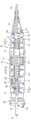
图1是用于假体植入物的递送设备的代表性实施方式的侧视图。Figure 1 is a side view of a representative embodiment of a delivery device for a prosthetic implant.
图2是在壳体的部分移除以图示手柄部分的内部的情况下图1的递送设备的手柄部分的侧视图。Figure 2 is a side view of the handle portion of the delivery device of Figure 1 with portions of the housing removed to illustrate the interior of the handle portion.
图3是图1的递送设备的远端部分的侧视图。FIG. 3 is a side view of the distal portion of the delivery device of FIG. 1 .
图4是在为了图示的目的而将部件纵向地间隔开的情况下导管组件的代表性实施方式的透视图。4 is a perspective view of a representative embodiment of a catheter assembly with the components spaced apart longitudinally for illustration purposes.
图5是沿着图4的线5-5获取的图4的导管组件的截面图。5 is a cross-sectional view of the catheter assembly of FIG. 4 taken along line 5-5 of FIG. 4. FIG.
图6是包括挠性部分的管的实施方式的透视图。Figure 6 is a perspective view of an embodiment of a tube including a flexible portion.
图7是在壳体的部分移除以图示手柄部分的内部的情况下图1的递送设备的手柄部分的透视图。7 is a perspective view of the handle portion of the delivery device of FIG. 1 with a portion of the housing removed to illustrate the interior of the handle portion.
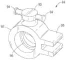
图8是可旋转构件的代表性实施方式的透视图。8 is a perspective view of a representative embodiment of a rotatable member.
图9是沿着图8的线9-9获取的图8的可旋转构件的截面侧视图。9 is a cross-sectional side view of the rotatable member of FIG. 8 taken along line 9-9 of FIG. 8. FIG.
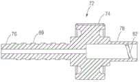
图10是牵引丝耦接构件的代表性实施方式的透视图。10 is a perspective view of a representative embodiment of a pull wire coupling member.
图11是外轴耦接构件的截面透视图。11 is a cross-sectional perspective view of the outer shaft coupling member.
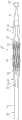
图12是在球囊轴处于挠曲状态并且外轴处于缩回位置的情况下图1的递送设备的侧视图。12 is a side view of the delivery device of FIG. 1 with the balloon shaft in a deflected state and the outer shaft in a retracted position.
图13是假体心脏瓣膜的代表性实施方式的透视图。13 is a perspective view of a representative embodiment of a prosthetic heart valve.
图14是图13的假体心脏瓣膜的侧正视图。FIG. 14 is a side elevational view of the prosthetic heart valve of FIG. 13 .
图15是图示使用递送设备的代表性方法的工艺流程图。15 is a process flow diagram illustrating a representative method of using a delivery device.
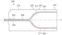
图16是根据另一实施方式的导管装置的远端部分的示意性侧视图,该导管装置具有延伸通过中心近侧管腔和两个远侧管腔的两个牵引丝。16 is a schematic side view of a distal portion of a catheter device having two pull wires extending through a central proximal lumen and two distal lumens, according to another embodiment.
图17是图16的导管装置的另一实施方式的远端部分的截面侧视图。17 is a cross-sectional side view of a distal portion of another embodiment of the catheter device of FIG. 16 .
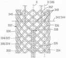
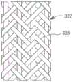
图18是图17的导管装置的编织层的部分的俯视图。FIG. 18 is a top view of a portion of the braid of the catheter device of FIG. 17 .
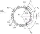
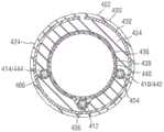
图19是沿着图17的线19-19获取的图17的导管装置的截面图。19 is a cross-sectional view of the catheter device of FIG. 17 taken along line 19-19 of FIG. 17 .
图20是图17的导管装置的透视图,示出了远侧顶端部分在远侧顶部部分的挠曲范围(α)内以各种角度挠曲的能力。20 is a perspective view of the catheter device of FIG. 17 illustrating the ability of the distal tip portion to flex at various angles within the deflection range (α) of the distal tip portion.
图21是图17的导管装置的编织层的示意性截面图,图示了牵引丝在导管装置的远侧部分中的代表性位置。21 is a schematic cross-sectional view of the braid of the catheter device of FIG. 17 illustrating a representative location of a pull wire in the distal portion of the catheter device.
图22是包括三个牵引丝的导管装置的另一实施方式的远端部分的截面侧视图。22 is a cross-sectional side view of a distal portion of another embodiment of a catheter device including three pull wires.
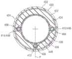
图23是沿着图22的线23-23获取的图22的导管装置的截面图。23 is a cross-sectional view of the catheter device of FIG. 22 taken along line 23-23 of FIG. 22. FIG.
图24是沿着图22的线24-24获取的图22的导管装置的截面图。24 is a cross-sectional view of the catheter device of FIG. 22 taken along line 24-24 of FIG. 22. FIG.
图25是沿着图22的线25-25获取的图22的导管装置的截面图。25 is a cross-sectional view of the catheter device of FIG. 22 taken along line 25-25 of FIG. 22. FIG.
图26图示了图17的导管装置的编织层的另一实施方式,其中编织构件以三轴编织方式进行编织。26 illustrates another embodiment of the braid of the catheter device of FIG. 17, wherein the braided member is braided in a triaxial braid.
具体实施方式Detailed ways
在具体实施方式中,一种用于经由患者的脉管系统植入假体经导管心脏瓣膜的递送设备包括用于操纵或调整球囊构件(包括径向地蜷曲在其上的假体瓣膜)的位置的操纵装置。球囊构件能够安装在另一导管内同轴地延伸的球囊导管的远端上。如在下面更详细地描述的,球囊构件和蜷曲的假体瓣膜能够通过导入器鞘管进入患者的脉管系统,并且一旦球囊构件和蜷曲的假体瓣膜到达身体内的合适位置,假体瓣膜就能够在治疗部位(例如,原生主动脉瓣膜)处扩张。操纵装置能够进一步用来准确地调整或“精调”所述假体瓣膜相对于期望部署位点(deployment location)的位置。In particular embodiments, a delivery device for implanting a prosthetic transcatheter heart valve via a patient's vasculature includes a means for manipulating or adjusting a balloon member (including a prosthetic valve radially crimped thereon) position of the manipulator. The balloon member can be mounted on the distal end of a balloon catheter that extends coaxially within another catheter. As described in more detail below, the balloon member and the crimped prosthetic valve can be accessed through the introducer sheath into the patient's vasculature, and once the balloon member and crimped prosthetic valve are in place within the body, the prosthetic valve The body valve can then be expanded at the treatment site (eg, the native aortic valve). The manipulation device can further be used to accurately adjust or "fine tune" the position of the prosthetic valve relative to the desired deployment location.
图1示出了根据一个实施方式的适合于向心脏递送假体心脏瓣膜12(例如,假体主动脉瓣膜)的递送设备10。设备10一般包括导管组件22,所述导管组件22具有第一外导管轴14、延伸通过外轴14的第二球囊导管轴16(例如,参见图2和7)、和延伸通过球囊导管轴16的第三导丝轴18(图3)。在图示的实施方式中,外轴14和球囊导管轴16适合于相对于彼此纵向地滑动,以便于假体瓣膜12在患者身体内的植入部位处的递送和定位,如在下面详细地描述的。1 illustrates a
递送设备还能够包括手柄部分20,导管组件从所述手柄部分20延伸。图2示出了从手柄部分20在球囊导管16和导丝轴18上延伸的外导管轴14。在图示的实施方式中,外导管14能够包括近端部分24和远端部分26(例如,参见图1),所述近端部分24设置在手柄部分20内部。球囊导管轴16也能够包括近端部分28和远端部分30,所述近端部分28设置在手柄部分20内部,所述远端部分30被配置为安装处于径向压缩状态的假体瓣膜12。The delivery device can also include a
参照图3,球囊导管轴16的远端部分30能够包含球囊安装部分32,所述球囊安装部分32被配置为支撑可膨胀球囊34。球囊的近端部分36能够折叠在球囊安装部分32的近侧肩部构件38(也称为“止挡件”)周围,所述近侧肩部构件38安装在球囊导管轴16的末端上,并且球囊34的远端部分40能够折叠在球囊安装部分的远侧肩部构件42周围,所述远侧肩部构件42安装在导丝轴18的远端部分上。在某些实施方式中,外轴14的远端在球囊32的近端近侧终止。在图示的实施方式中,球囊34的近端部分36固定到球囊导管轴16。球囊的远端部分40能够固定到鼻锥44,所述鼻锥44设置在导丝轴18上或以其它方式耦接到导丝轴18。Referring to FIG. 3 , the
更详细地转向导管组件22,图4图示了为了图示的目的而纵向地间隔开的导管组件的部件。图5是沿着图4的线5-5获取的导管组件22的截面图。在某些实施方式中,外轴14能够包含内层46和外层48。在一些实施方式中,内层46能够被配置为向外轴提供轴向强度或刚度以减少外轴在轴向负荷下(例如,当推动导管组件通过患者的脉管系统时)挠曲的倾向,而外层48能够比内层更具挠性。例如,在图示的实施方式中,内层被配置为由多个螺旋缠绕的细线或细丝52限定的管50(例如,可从Fort Wayne Metals ResearchProductsCorp.获得的Helical Hollow
在图示的实施方式中,管50能够包括内和外层细丝52。然而,应当理解,管50能够包括任何合适层数的细线,诸如单层或三层。细丝52能够具有圆形截面或任何其他合适形状的截面。此外,细丝52能够具有均匀的直径或不均匀的直径。例如,取决于所期望的具体性质,细丝的直径能够在内和外层细丝之间改变,和/或直径能够围绕管50的截面径向地或沿着其长度纵向地改变。在可选实施方式中,管50能够是编织的金属丝管或表现出合适刚度性质的任何其他结构。例如,在一些实施方式中,管50能够由编织的金属丝制成(例如,一个在一个上型式(one-over-one pattern)的304级不锈钢扁丝和/或圆丝编织物)。在可选实施方式中,管50能够是挤压的聚合物管或激光切割的金属管(诸如沿着其长度包括一个或多个切割型式的激光切割的海波管)、或由具有比球囊导管轴16相对更高硬度的任何其他合适材料制成的管。In the illustrated embodiment, the
覆盖管50的外层48能够是聚合物覆盖物,诸如聚醚嵌段酰胺(商业上可作为

球囊导管轴16能够同轴地设置在外轴14内。外轴14能够可相对于球囊导管轴16移动,如在下面更详细地描述的。因此,球囊导管轴16和外轴14中的任一者或两者能够包括低摩擦涂层(诸如聚四氟乙烯(PTFE)或氟化乙烯丙烯(FEP)),以促进轴相对于彼此的滑动。参照图5,球囊轴能够限定管腔或流体通道54,所述管腔或流体通道54可流体地连接到流体源(例如,盐水)以膨胀球囊并冲洗球囊轴与导丝轴之间的空间。例如,在图示的实施方式中,球囊导管轴16的近端部分28能够耦接到分叉的连接器构件61(图2)。连接器构件61能够包括第一管状部分63,所述第一管状部分63与球囊轴的管腔54流体连通。(例如,来自外部流体源的)流体能够流过连接器构件61的管状部分63、流过球囊轴的管腔54、流过球囊安装部分32的近侧和远侧肩部38和42中的通道(图3)。流体然后能够流至球囊34的近和远端部分36、40中,以膨胀球囊并扩张瓣膜12。The
在图示的实施方式中,球囊导管轴16还能够限定牵引丝58(例如,参见图2和7)能够在手柄部分与球囊导管轴的远端处或附近的牵引丝附接部分60(例如,参见图1和12)之间延伸通过的牵引丝管腔56。张紧或释放牵引丝58能够允许操作者调整导管组件的弯曲来帮助引导设备通过患者的脉管系统并且具体地主动脉弓,如在下面进一步描述的。在一些实施方式中,牵引丝管腔56还能够包括防摩擦涂层(例如,PTFE或FEP),以减少管腔与牵引丝58之间的滑动摩擦。In the illustrated embodiment, the
球囊导管轴16能够是挠性的,使得张紧或释放牵引丝58引起球囊轴的挠曲或伸开。因此,球囊导管轴16能够由各种合适材料(诸如编织的或盘绕的不锈钢丝或其组合)中的任一种或各种生物相容性聚合物材料(诸如尼龙或聚醚嵌段酰胺(例如,
导丝轴18能够同轴地设置在球囊导管轴16内,并且能够限定用于接收导丝62(例如,参见图1和3)的管腔。导丝轴18能够被配置为在牵引丝58上的张力的施加或释放后随着球囊导管轴16挠曲。在图示的实施方式中,连接器构件61能够包括第二管状部分65,所述第二管状部分65限定与导丝轴18的管腔连通的管腔,导丝62能够插入通过所述导丝轴18的管腔。导丝轴18能够由与球囊轴类似的合适挠性材料(诸如尼龙、编织的不锈钢丝或聚合物材料)制成。导丝轴的内表面还能够包括防摩擦涂层(例如,PTFE)以减少管腔与导丝62之间的滑动摩擦,并且可以形成有具有对应于例如球囊导管轴16的不同程度的挠性的纵向区段。The
图6图示了外轴14的管50的另一构造,其中管的远端部分25包括保持部分27。在某些实施方式中,保持部分27能够被配置为例如保持构件,诸如(例如,通过焊接)固定在管的管腔内部的金属环。在某些实施方式中,保持部分27能够是细丝52焊接在一起或以其它方式结合到彼此的区域。位于保持部分27远侧的细丝52的部分然后能够分开或展开(例如,通过切割管50的远端部分并且部分地展开细丝),以限定相对更挠性的部分29。细丝52的远侧顶端然后能够重新焊接到彼此,使得细丝在各自的远侧顶端处和在保持部分27处耦接到彼此,但是沿着挠性部分29的长度不耦接到彼此。以此方式,当管50如在图6中示出的那样弯曲或挠曲时,在挠性部分29中的细丝的部分能够相对于彼此独立地移动并且彼此分开,由此为外轴14的远端部分提供更大程度的挠性而不实质上损害外轴的轴向刚度。FIG. 6 illustrates another configuration of the
在某些实施方式中,展开挠性部分29中的细丝52还能够导致相邻细丝之间的更大间距,和/或能够允许挠性区域中的细丝的部分的间距(pitch)相对于挠性区域近侧的细丝的部分的间距改变。例如,通过展开挠性区域中的细丝,挠性区域中的细丝的部分的间距能够随着管50的挠曲或伸开而相对于挠性部分外部的细丝的部分的间距改变。In certain embodiments, unfolding the
图6的管构造能够与本文中描述的导管轴和/或递送手柄实施方式中的任一个一起使用。此外,挠性部分29不必限制于管50的远端,而且能够根据需要沿着管的长度的合适部分(包括沿着管的整个长度)延伸。在一些实施方式中,管50的远端部分能够被定形为具有预定的弯曲,如在图1和6中示出的。在包括挠性部分29的实施方式中,挠性部分还能够被定形为使得它具有预定的弯曲。可选地,管50能够是直的而无任何预设的弯曲。The tube configuration of Figure 6 can be used with any of the catheter shaft and/or delivery handle embodiments described herein. Furthermore, the
在进一步实施方式中,细丝52能够具有沿着管50的远端部分25的长度减小的厚度,使得管具有减小的外径来促进挠性。例如,在一些实施方式中,管的远端部分处的细丝的厚度能够根据长度减小,使得管50的直径从第一外径D1减小到第二外径D2(图6)。以此方式,管50的远端部分能够具有渐缩(逐渐变细,tapered)的轮廓,并且管的远端部分的挠性能够提高。在示例性实施方式中,管50的外径能够在相距管的远端大约15cm、大约10cm或大约5cm的长度上从大约0.155英寸减小到大约0.135英寸。外径的这种减小能够通过例如沿着其长度将细丝研磨以实现期望的厚度、或通过其他方式改变管的远端部分处的细丝股的厚度来实现。In further embodiments, the
再次参照图1和2,图示的实施方式中的手柄部分20能够包含第一和第二壳体部分64、66,所述第一和第二壳体部分64、66可耦接到彼此以限定内部腔室68(图2和7)。如在图2和7中最佳示出的,手柄部分20能够包括操纵组件70,所述操纵组件70用于操纵递送设备通过患者的脉管系统(例如,主动脉弓)并且将球囊和假体瓣膜定位在原生心脏瓣膜的瓣环中。操纵组件70能够包括被配置为可旋转构件72的控制构件,其包括旋钮部分74、第一螺纹轴76、和被配置为接收第二螺纹轴80的内螺纹管状部分78。在图示的实施方式中,可旋转构件72和第一螺纹轴76能够是球囊轴挠曲子组件37的部分,并且第二螺纹轴80能够作为外轴移动子组件39的部分与可旋转构件接合。在图示的实施方式中,球囊轴挠曲子组件37和外轴移动子组件39能够是可通过可旋转构件的旋转联合操作的,如在下面更详细地描述的。Referring again to Figures 1 and 2, the
图8和9更详细地图示了可旋转构件72。在图示的实施方式中,第一螺纹轴76和管状部分78与旋钮部分74一体形成。然而,应当理解,旋钮部分74、第一螺纹轴76和/或管状部分78也能够是单独形成的部件。此外,尽管可旋转构件72被图示有从旋钮部分74近侧地延伸的第一螺纹轴76,但是应当理解,可旋转构件的取向能够颠倒而不实质上改变其操作原理。8 and 9 illustrate the
可旋转构件72以及第一和第二螺纹轴76、80能够同轴地设置在球囊导管轴16周围。如上面陈述的,第二螺纹轴80能够作为外轴移动子组件39的部分接收在可旋转构件的管状部分78中。可旋转构件的管状部分78能够包括限定在该管状部分的内表面上的内螺纹82(图9),所述内螺纹82能够接合第二螺纹轴80的外部上的外螺纹67。以此方式,可旋转构件72在由双头箭头21(图7)指示的方向上的旋转引起第一螺纹轴76围绕球囊导管轴16在相同方向上的对应旋转。可旋转构件72的旋转还引起第二螺纹轴80沿着球囊导管轴在双头箭头23的方向上在近侧位置与远侧位置之间的纵向运动。The
再次参照图7,操纵组件70的球囊轴挠曲子组件37能够进一步包括牵引丝耦接构件84,所述牵引丝耦接构件84可移动地设置在第一螺纹轴76上。在图示的实施方式中,牵引丝58能够在球囊导管轴的近端部分28附近离开球囊导管轴16的牵引丝管腔56。从它离开球囊导管轴的位置追踪牵引丝58,牵引丝58能够径向地延伸远离球囊导管轴,并且至少部分地缠绕被配置为支柱88的牵引丝引导构件。在图示的实施方式中,牵引丝引导构件88从手柄的第二壳体部分66在大致垂直于手柄部分的纵向轴线75(图2)的方向上延伸到腔室68内。丝的近侧部分能够固定地固定到牵引丝耦接构件84的安装部分90。在图示的实施方式中,牵引丝引导构件88能够引导牵引丝58径向地远离球囊导管轴16到达牵引丝耦接构件84。应当理解,牵引丝引导构件88不必被配置为支柱,而且能够是例如斜坡构件或任何其他合适的结构。Referring again to FIG. 7 , the balloon
图10更详细地图示了牵引丝耦接构件84。在图示的实施方式中,牵引丝耦接构件84能够包括管状主体部分92,安装部分90从所述管状主体部分92延伸。安装部分90能够包括一个或多个牵引丝附接构件,所述一个或多个牵引丝附接构件被配置为突出构件94(例如,在图示的构造中两个),牵引丝58能够系到或以其它方式附接到所述突出构件94。主体部分92的内表面能够限定螺纹96,所述螺纹96能够接合第一螺纹轴76的外螺纹69。以此方式,第一螺纹轴76的旋转能够引起牵引丝耦接构件84沿着第一螺纹轴在近侧位置与远侧位置之间在由双头箭头53(图7)指示的方向上的对应纵向运动。牵引丝耦接构件的这种纵向运动能够增加或减小牵引丝58中的张力,由此挠曲或伸开球囊轴16。因此,牵引丝耦接构件84的近侧位置能够对应于牵引丝58的基本上松弛状态和球囊轴16的伸开状态(不存在导管组件的任何定形弯曲),并且牵引丝耦接构件的远侧位置能够对应于牵引丝的张紧状态和球囊轴的完全挠曲状态(例如,参见图12)。FIG. 10 illustrates the pull
牵引丝耦接构件还能够包括在其之间限定凹槽的一对延伸部分98。在组装状态下,凹槽能够接收被配置为凸耳的引导构件或耦接到第一壳体部分64的延伸部分,所述耦接到第一壳体部分64的延伸部分类似于在图7中图示的耦接到第二壳体部分66的延伸部分77。延伸部分能够平行于第一螺纹轴76延伸,并且能够具有基本上对应于牵引丝耦接构件84沿着第一螺纹轴76的可允许行进长度的长度。通过接收手柄壳体的延伸部分,当牵引丝耦接构件84沿着螺纹轴76的长度移动时,延伸部分98能够防止牵引丝耦接构件84的旋转。在可选实施方式中,延伸部分98能够位于牵引丝耦接构件84的相对侧上,使得它们接合延伸部分77。在进一步可选实施方式中,牵引丝耦接构件84能够在两侧上包括延伸部分98,以接合手柄的第一和第二壳体部分的各自延伸部分。The pull wire coupling member can also include a pair of
返回到图7,外轴移动子组件39能够包括外轴耦接构件86,所述轴耦接构件86设置在球囊导管轴16周围。外轴耦接构件86能够包括近端部分31和远端部分33。近端部分31能够耦接到引导构件35,并且远端部分33能够被配置为接收外轴14。引导构件35能够设置在第二螺纹轴80的远端上,使得由可旋转构件72的旋转引起的第二螺纹轴80的纵向运动反过来引起引导构件35在双头箭头23(图7)的方向上的对应纵向运动。这反过来引起外轴耦接构件86和外轴14在近侧位置与远侧位置之间的纵向运动。因此,外轴移动子组件39的近侧位置能够对应于外轴14相对于球囊导管轴16的近侧位置,并且子组件39的远侧位置(在图7中图示的位置)能够对应于外轴14相对于球囊导管轴16的远侧位置。在图示的实施方式中,引导构件35能够包括与牵引丝耦接构件84的延伸部分98类似的延伸部分57。延伸部分57能够接收从第一壳体64的壁延伸的引导构件(类似于第二壳体部分66的延伸部分79),使得当第二螺纹轴80相对于可旋转构件纵向地平移时防止第二螺纹轴80旋转。在可选实施方式中,延伸部分57也能够位于相对侧上使得它们接合延伸部分79,和/或引导构件35能够在两侧上包括延伸部分以接合第一和第二手柄部分的各自延伸部分。Returning to FIG. 7 , the outer
图11更详细地图示了外轴耦接构件86的截面图。远端部分33能够限定管腔41,所述管腔41被配置为接收并保持外轴14的近端部分。冲洗端口43能够从耦接构件86延伸,并且能够限定与外轴14流体连通的管腔45。冲洗端口43能够与管47(图7)连接,所述管47离开手柄部分并且反过来能够在手柄外部连接到旋塞阀、流体源等。球囊导管轴16能够不间断地延伸通过外轴耦接构件86,并且能够延伸通过密封构件(未示出),所述密封构件设置在外轴耦接构件86与引导构件35之间来密封外轴耦接构件的管腔。11 illustrates a cross-sectional view of the outer
返回到图1,可旋转构件72能够是可通过限定在组装的手柄部分的侧面部分上的开口51接近的。这能够允许可旋转构件被一只手的拇指、(一个或多个)手指或其组合操作。Returning to Figure 1, the
如上面描述的,操纵组件70的球囊轴挠曲子组件37和外轴移动子组件39能够是可通过可旋转构件72的旋转联合操作的。图1图示了在外轴14处于相对于球囊导管轴16的远侧位置的情况下的递送设备。可旋转构件72在第一方向(例如,从用户在图12的箭头73的方向上的角度下顺时针)上的旋转能够引起第一螺纹轴76的顺时针旋转和牵引丝耦接构件84沿着螺纹轴76的对应远侧运动。当牵引丝耦接构件84沿着螺纹轴76移动时,这反过来能够将张力施加于牵引丝58,引起球囊导管轴16挠曲,使得球囊安装部分32在由图12的箭头71的方向上偏转或呈曲线形(curved)。相反,旋钮74在相反方向上的旋转能够相对于球囊导管轴16推进外轴14,并且将球囊导管轴返回到非偏转状态。As described above, the balloon
同时,可旋转构件72的旋转能够引起第二螺纹轴80和外轴耦接构件86相对于可旋转构件的对应近侧运动。这反过来能够引起外轴14相对于球囊导管轴16在图12的箭头55的方向上的近侧运动,同时使球囊导管轴挠曲。At the same time, rotation of the
通过本文中描述的实施方式以及导管组件构造实现的同时的球囊导管轴16的挠曲和外轴14的缩回能够提供显著的优点。例如,通过使外轴14比球囊导管轴16相对更刚性或更不挠性,外轴能够当它在球囊导管轴的长度上设置在远侧位置中时提供轴向负载情况下的柱形强度和抗屈曲性。当导管组件推进通过狭窄通道(诸如通过导入器鞘管或通过身体内的狭窄血管)时,这能够减少或消除导管组件的不期望的屈曲。本文中描述的导管构造也能够允许导管组件22的外径减小(例如,到12Fr或更小),同时在插入期间提供合适的轴向刚度性质并且当操纵时提供挠性性质。在可选实施方式中,外轴14不必比球囊导管轴16更刚性。然而,当外轴处于远侧位置时,外轴提高了沿着导管组件的远端部分的总体刚性。The simultaneous deflection of the
一旦在身体内部,当球囊导管轴16挠曲时同时缩回外轴14的能力能够提高通过球囊导管轴可实现的挠曲程度,允许导管组件被操纵通过曲折的解剖结构(诸如主动脉弓)。当挠曲球囊导管轴16时同时缩回外轴14还能够在控制球囊安装部分32的位置的能力方面提供改善。例如,由于与球囊导管轴16相比外轴14的相对更高的刚度(或由于与单独的球囊导管轴相比外轴和球囊导管轴的组合的相对更高的刚度),外轴的远端部分26相对于球囊导管轴的位置能够确定球囊导管轴开始弯曲的点或其“挠曲点”。这在图12中进行图示,其中外轴14和设置在外轴内的球囊导管轴16的部分是相对直的(不存在任何定形弯曲),并且球囊导管轴在它从外轴的远端部分出现(emerges)的点处开始挠曲。当挠曲球囊导管轴时缩回外轴还能够允许用户更精确地控制球囊导管轴的弯曲半径(曲率半径,radius ofcurvature)、以及球囊导管轴的挠曲程度。Once inside the body, the ability to simultaneously retract the
本文中描述的实施方式还能够在不同用户之间的球囊导管轴的弯曲位置或“挠曲点”以及球囊导管轴的弯曲程度方面提供改善的重复性。换言之,因为球囊轴挠曲子组件和外轴移动子组件机械地联接,所以即使当递送设备被不同的用户操作时,也能够促使球囊导管轴针对外轴相对于球囊导管轴的给定位置在相同的位置处挠曲并且实现基本上相同的弯曲程度。Embodiments described herein can also provide improved repeatability in the location or "flexion point" of the balloon catheter shaft and the degree of curvature of the balloon catheter shaft between different users. In other words, because the balloon shaft deflection subassembly and the outer shaft movement subassembly are mechanically coupled, a given reference of the balloon catheter shaft for the outer shaft relative to the balloon catheter shaft can be facilitated even when the delivery device is operated by different users The locations flex at the same locations and achieve substantially the same degree of bending.
应当理解,本文中描述的实施方式不限于所示出的具体构造。例如,在图示的实施方式中,球囊轴挠曲子组件37在手柄部分20内部位于外轴移动子组件39近侧。然而,应当理解,在可选实施方式中,各自子组件的位置能够颠倒。此外,尽管当第二螺纹轴80可纵向移动时第一螺纹轴76相对于旋钮部分74纵向地固定,但是应当理解,这种构造能够颠倒。此外,可旋转构件72的运动能够通过除了螺纹轴76、80外的其他传递给各自子组件37、39的各种部件。例如,在一些实施方式中,各自子组件能够包括齿轮、杠杆或用于代替或结合螺纹轴来传递运动的其他机构。这些元件能够用来例如将球囊轴挠曲的速率与外轴缩回的速率分离。在其他实施方式中,操纵组件能够包括多个牵引丝,所述多个牵引丝附接在沿着球囊导管轴16的长度的相同或不同位置处,以例如便于球囊导管轴或其部分在多个方向上的挠曲。It should be understood that the embodiments described herein are not limited to the specific constructions shown. For example, in the illustrated embodiment, the balloon
图13和14示出了根据一个实施方式的能够与递送设备10一起使用的假体心脏瓣膜100。假体心脏瓣膜100包含框架或支架102和由该框架支撑的小叶结构104。在具体实施方式中,心脏瓣膜100适合于植入在原生主动脉瓣膜中,并且能够使用例如上面描述的递送设备10植入在身体中。假体瓣膜100也能够使用本文中描述的其他递送设备中的任一种植入在身体内。因此,框架102通常包含可塑性扩张材料,诸如不锈钢、镍基合金(例如,镍-钴-铬合金)、聚合物或其组合。在其他实施方式中,假体瓣膜100能够是具有由自扩张材料(诸如镍钛诺)制成的框架的可自扩张假体瓣膜。当假体瓣膜是自扩张瓣膜时,递送设备的球囊能够用鞘管或类似的约束装置来代替,所述鞘管或类似的约束装置保持假体瓣膜处于径向压缩状态以便递送通过身体。当假体瓣膜在植入位置处时,假体瓣膜能够从鞘管释放,并且因此允许扩张到其功能尺寸。应当注意,本文中描述的递送设备中的任一个能够适合于与自扩张瓣膜一起使用。在一个实施方案中,例如,球囊导管轴能够用具有远端部分的轴来代替,所述远端部分包含被定尺寸为容纳处于其径向压缩状态的假体瓣膜的鞘管。递送设备的手柄能够被配置为相对于假体瓣膜缩回轴,以从鞘管部署瓣膜。13 and 14 illustrate a
图15图示了使用本文中描述的递送装置植入假体心脏瓣膜的方法的代表性实施方式。在方框202处,递送装置能够经由例如股动脉中的切口导入到患者的身体内。递送装置能够包含手柄部分、第一细长轴和第二轴,所述第一细长轴从手柄部分延伸,所述第二轴同轴地设置在第一轴内,并且具有安装处于径向压缩状态的假体心脏瓣膜的远端部分。Figure 15 illustrates a representative embodiment of a method of implanting a prosthetic heart valve using the delivery devices described herein. At
在方框204处,第二轴的远端部分能够朝向原生心脏瓣膜推进,其中推进的动作包含远侧地推动手柄部分以便朝向原生心脏瓣膜远侧地推动递送装置通过患者。At
在方框206处,通过操作耦接到手柄部分的操纵组件,装置能够操纵通过患者的脉管系统。操纵组件的操作能够引起第一轴相对于第二轴的近侧或远侧运动和同时的第二轴的挠曲或伸开。At
在方框208处,在假体心脏瓣膜已经移动到期望的植入位置之后,假体心脏瓣膜能够径向地扩张以接合原生心脏瓣膜的瓣环,诸如通过膨胀球囊或通过从鞘管部署瓣膜。At
图16示出了根据另一实施方式的导管装置300。在图示的实施方式中,导管装置300包含第一牵引丝304、第二牵引丝306和轴302,所述轴302具有近侧部分315(图20)和可操纵远侧部分316。在图示的实施方式中,远侧部分316能够比近侧部分315相对更具挠性。近侧部分315能够耦接到手柄(未示出),所述手柄能够具有一个或多个调整机构(例如,类似于操纵组件70),用于增加和减小牵引丝304、306中的张力。在具体实施方式中,导管装置300能够具有两个调整机构,所述两个调整机构中的每一个连接到各自的牵引丝304、306。在美国专利申请公开号2013/0030519中描述了具有两个调整机构的导管装置的示例。Figure 16 shows a
主体310能够进一步包含主牵引丝管腔308,所述主牵引丝管腔308平行于轴的中心轴线X延伸通过近侧部分315并且通过远侧部分316的近侧区段318。主牵引丝管腔308然后能够分成第一远侧牵引丝管腔312和第二远侧牵引丝管腔314,所述第一远侧牵引丝管腔312和第二远侧牵引丝管腔314彼此偏离,并且然后在成角度间隔开的位置处大致平行于彼此延伸通过轴的远侧部分316的远侧区段320。牵引丝304、306因此能够在轴的近侧部分315和远侧部分316的近侧区段318期间延伸通过主牵引丝管腔308。第一和第二牵引丝304、306然后分开以分别在远侧部分316的远侧区段320期间延伸到第一远侧牵引丝管腔312和第二远侧牵引丝管腔314内。The
图17图示了导管装置300的另一实施方式,其中第一牵引丝304同轴地设置在第一牵引丝管腔322中并且可相对于第一牵引丝管腔322移动,并且第二牵引丝306同轴地设置在第二牵引丝管腔324中并且可相对于第二牵引丝管腔324移动。牵引丝管腔322、324能够沿着基本上牵引丝的整个长度与牵引丝304、306共同延伸。因此,为了清楚起见,以下描述的部分仅参照管腔322、324进行,但是所描述的牵引丝管腔322、324的位置、方向改变等也适用于各自的牵引丝304、306,并且反之亦然,除非另有说明。此外,在其他实施方式中,牵引丝304、306不必包括管腔。17 illustrates another embodiment of a
牵引丝管腔322、324能够设置在牵引丝管道326中,所述牵引丝管道326并入到轴的壁内并且延伸通过轴的近侧部分315和远侧部分316的近侧区段318。牵引丝管道326然后能够在远端部分338处终止,并且牵引丝管腔322、324能够从管道326延伸并围绕轴302的圆周偏离彼此。牵引丝管腔322、324然后能够在成角度间隔开的位置处大致平行于彼此延伸通过远侧区段320。牵引丝304、306能够从其各自的管腔延伸,其中它们能够在导管轴302的远端处或附近耦接到拉环328,并且当张紧以操纵导管轴时能够作用在拉环328上,如在下面进一步描述的。在其他实施方式中,牵引丝管腔322、324能够在近侧部分315和近侧区段318中成组在一起,并且不必包括单独的牵引丝管道。The
在一些实施方式中,导管轴302能够包含不同材料和/或具有不同硬度或弯曲性质的材料的多个层。例如,参照图18和19,轴302的远侧部分316能够包括第一或外层330、第二层332和第三或内层334(图19)。在图示的实施方式中,内和外层334、330能够是例如各种挠性聚合物材料(诸如
在某些实施方式中,第二层332能够是编织层,如在图18中最佳示出的。编织层332能够包含多个编织构件336(例如,金属、天然或合成丝、纤维、细线、纱线、丝线等)。编织层332能够具有任何期望数量的编织构件336,所述任何期望数量的编织构件336能够沿着任何合适数量的载体轴线取向并且编织在一起。例如,编织构件336能够以双轴编织方式(如在图18中示出的)、以三轴编织方式(如在图26中示出的)、或以任何其他编织型式编织在一起。为了便于图示,以下讨论参照在图18中图示的双轴编织物进行,但是本文中描述的构造能够适用于具有任何合适编织型式的编织物。In certain embodiments, the
编织层332的编织构件336能够在相交点(在本文中称为“交错(picks)”340)处在彼此上方或下方交叉。交错340能够围绕编织层332的圆周与彼此成角度地间隔开,其中成角度分离对应于例如编织构件336的数量和编织构件布置在其中的轴线的数量。例如,以三轴编织方式编织的包括16个编织构件336的编织层能够具有围绕编织层的圆周间隔开45°的八个交错,如在图21中最佳示出的。The braided
返回到图18,为了本申请的目的,一“行”交错指的是沿着轴302的轴线X位于相同纵向距离处的交错340。因此,例如,沿着垂直于轴线X的平面342定位的交错340限定一行344交错。为了本申请的目的,沿着与轴302的轴线X平行的轴线与彼此对齐的交错340称为一“列”交错。因此,沿着轴线X'定位的交错340限定一列346交错。Returning to FIG. 18 , for the purposes of this application, a "row" of staggers refers to
仍然参照图18,牵引丝管道326能够并入到编织层332内。例如,在一些实施方式中,在一个或多个方向上取向的编织构件336能够在牵引丝管道326上经过,而在一个或多个其他方向上取向的编织构件336能够在牵引丝管道下经过,如在图18中示出的。在其他实施方式中,牵引丝管道326能够位于编织层332下方,使得编织物中的所有编织构件336都在牵引丝管道上方经过。Still referring to FIG. 18 , the
牵引丝管道326能够并入到编织层内,使得牵引丝管道沿着选定的一列交错340延伸。在离开牵引丝管道326后,管腔322、324并且因此牵引丝304、306能够彼此偏离,同时保持并入到编织层332内。可选地,管腔322、324能够从编织物中移除,并且重新导入到牵引丝管道326远侧的编织物内,如关于图22-25的实施方式更详细地描述的。在某些构造中,牵引丝管腔322、324能够以与交错340的间隔有关的递增方式彼此偏离。例如,在图18中,管腔322能够偏离牵引丝管道326,使得管腔322(并且因此,牵引丝304)的远侧部分348从管腔322的近侧部分350成角度地偏移两列346交错340。在图示的实施方式中,成角度偏离发生在两行344交错340的空间内,但是根据需要,转变可以发生在任何合适的行数内。第二牵引丝306和管腔324能够从牵引丝管腔326偏离相同行344和列346数的交错340,但是在相反方向上偏离第一牵引丝管腔322,使得管腔324的远侧部分352从管腔的近侧部分354成角度地偏移两列344交错340。以此方式,管腔322、324的远侧部分348、352能够围绕牵引丝管道326与彼此对称地间隔开。The
图19和21示出了两个牵引丝管腔322、324(并且因此,牵引丝304、306)的远侧部分348、352沿着由轴302的侧壁限定的弧形的成角度定位。参照图19,第一牵引丝管腔322能够沿着第一轴线B1定位,所述第一轴线B1从轴302的中心轴线X径向地延伸到第一管腔322。第二牵引丝管腔324能够沿着第二轴线B2定位,所述第二轴线B2从轴302的中心轴线X径向地延伸到第二管腔322。如图所示,管腔322、324的远侧部分348、352沿着由轴的侧壁限定的弧形在轴线B1与B2之间与彼此成角度地间隔开角度α。角度α能够是大于零度并且多达360度的任何角度。在所示出的实施方式中,角度α为大约120°。FIGS. 19 and 21 illustrate the angled positioning of the
在牵引丝管腔322、324沿着编织层332的多列346交错340对齐的实施方式中,轴线B1和B2能够与多列346交错相交,使得角度α取决于多列交错之间的成角度间隔。例如,参照图21,以三轴型式编织的包括16个编织构件336的管状编织层332能够包括沿着其圆周间隔的八个交错340。在这种构造中,每个交错340与相邻交错分开大约45°。图21示意性地图示了一种构造,其中第一牵引丝管腔322从牵引丝管道326偏移一列交错(例如,在图21中位于各自编织构件336之间),并且与轴线B1相交。第二牵引丝管腔324也从牵引丝管道326偏离一列交错,并且与轴线B2相交。这导致管腔322、324的各自远侧部分348、352之间90°的成角度分离α1。In embodiments where the
通过将管腔322、324的远侧部分348、352从管道326偏移相等列346数的交错340,90°(每个一列)、180°(每个两列),270°(每个三列)和360°(每个四列)的成角度间隔能够实现。管腔322、324的远侧部分348、352也能够彼此偏移不同的列346数。例如,如果一个管腔(例如,管腔322)偏移n列346,那么另一个管腔(例如,管腔324)能够偏移n+1列。在图21中也示出了这种构造的一个代表性示例,其中管腔322从管道326偏移一列并且与轴线B1相交,而第二管腔(由324'指示)在相反方向上从管道偏移两列并且与轴线B3相交。在具有16个编织构件336的三轴编织物中,这导致各自远侧部分348、352'之间的135°的成角度间隔。遵循一个管腔偏移n列346并且另一个管腔偏移n+1列的规则,135°、225°和315°的成角度间隔能够实现。By offsetting the
参照图20,这种双丝构造允许轴302具有主要挠曲区段(对应于可操纵远侧部分316的近侧区段318)和次要挠曲区段(对应于可操纵远侧部分316的远侧区段320)。在一些实施方式中,取决于两个区段之间的期望相对挠性,主要挠曲区段318的硬度与次要挠曲区段320的硬度相同、高于或低于次要挠曲区段320的硬度。主要挠曲区段具有比主轴更低的硬度,在图示的实施方式中,所述主轴是主要挠曲区段近侧的轴302的基本上不可操纵的部分。在一些实施方式中,主轴具有比次要挠曲区段更高的硬度,所述次要挠曲区段反过来具有比主要挠曲区段更高的硬度。Referring to FIG. 20 , this dual wire configuration allows the
当一个或两个牵引丝304、306在张力下时,主要挠曲区段318在各自的挠曲平面P(图19)中挠曲或呈曲线形。借助于牵引丝304、306从可操纵远侧部分316近侧地紧邻彼此延伸通过管腔322、324,张紧任一个或两个牵引丝对调整主要挠曲区段318在其各自挠曲平面P中的弯曲是有效的。通过将不同的张力施加于牵引丝,能够引起次要挠曲区段320相对于主要挠曲区段318在各种不同的方向上挠曲。例如,将相同量的张力施加于每个牵引丝304、306引起次要挠曲区段320在与主要挠曲区段相同的平面P中呈曲线形。相对于第二牵引丝306增加第一牵引丝304中的张力引起次要挠曲区段320在远离主要挠曲区段318的平面P的第一方向上呈曲线形或弯曲(在图20中以实线示出)。同样地,第二牵引丝306中的相对于第一牵引丝304增加的张力引起次要挠曲区段320在远离主要挠曲区段318的平面P的与第一方向相反的第二方向上呈曲线形或弯曲(在图20中以虚线示出)。When one or both pull
在图示的实施方式中,次要挠曲区段320允许导管装置300的远侧顶端进入通过由第一挠曲范围和第二挠曲范围限定的球体的表面的一部分近似的地点,在一些实施方式中其对应于球坐标系的角度分量。第一范围具有角度宽度或方位角宽度α(例如,参见图19和21)(由径向轴线B1和B2界定)。第二范围具有极角,该极角具有在X轴线处或附近的最小值(大约0°)和取决于次要挠曲区段320的硬度和长度的最大值(最大挠曲状态)。因此,任选地当部分地松弛牵引丝306时张紧牵引丝304大致沿着轴线B1径向向外挠曲次要挠曲区段320。类似地,牵引丝306可操作为沿着轴线B2挠曲次要挠曲区段302。通过调整牵引丝304、306之间的相对张力,导管装置300的远侧顶端能够操纵到该空间中的任何中间位置或点。In the illustrated embodiment, the
因此能够使次要挠曲区段320在任何径向挠曲平面中在角度α内挠曲。牵引丝304、306的角度定位因此限定了用于次要挠曲区段320的方位角或第一挠曲范围α。在图19中示出的实施方式中,这种挠曲方向能够是在相对于在主要挠曲平面大约-60°与大约+60°之间的任何平面中,其中0°方向是主要挠曲平面P。因此,在这种情况下,第一挠曲范围α为大约120°。在诸如图19和21的实施方式中,其中牵引丝304、306在编织层中根据它们对齐所沿着的多列346交错340间隔开,角度α和对应的第一挠曲范围能够为大约90°(例如,大约-45°至大约+45°)、大约180°(例如,大约-90°至大约+90°)等。在其他实施方式中,角度α和对应的第一挠曲范围能够改变诸如大约140°(大约-70°至大约+70°)、大约130°(大约-65°至大约+65°)、大约110°(大约-55°至大约+55°)、大约100°(大约-50°至大约+50°)、大约90°(大约-45°至大约+45°)、大约80°(大约-40°至大约+40°)、大约70°(大约-35°至大约+35°)、或大约60°(大约-30°至大约+30°)。The
在其他实施方式中,次要挠曲区段320的第一挠曲范围不必是相对于主要挠曲平面P对称的。例如,在第一管腔322的远侧部分348中的第一牵引丝304的部分能够与牵引丝管道326(和主要挠曲平面P)成角度地间隔开第一角度θ1,并且在第二管腔324的远侧部分352中的第二牵引丝306的部分能够与牵引丝管道326(和主要挠曲平面P)成角度地间隔开第二角度θ2,其中θ1和θ2不等于彼此。以此方式,次要挠曲区段320的第一挠曲范围包含主要挠曲平面P,但是能够调整为在主要挠曲平面P的一侧上比在另一侧上延伸更远。In other embodiments, the first deflection range of the
将牵引丝并入到编织层内能够提供优于已知导管系统的显著优点。例如,包括围绕导管轴的圆周与彼此成角度地间隔开的多个牵引丝的传统方法需要限定在心轴中的凹槽来在导管的制造期间保持牵引丝(或间隔器心轴(mandrel))。然而,如果期望牵引丝从一个角度位置呈曲线形到另一个角度位置,将牵引丝定位在心轴中的对应呈曲线形的凹槽中将会引起牵引丝将导管锁定到心轴,使心轴从导管的移除复杂化。将牵引丝并入到编织层内消除了这种问题,并且允许牵引丝多次并且在任何位置处改变方向。Incorporation of a pull wire into the braid can provide significant advantages over known catheter systems. For example, conventional methods involving multiple pull wires angularly spaced from each other around the circumference of the catheter shaft require grooves defined in the mandrel to retain the pull wires (or spacer mandrels) during manufacture of the catheter . However, if it is desired to curve the pull wire from one angular position to another, positioning the pull wire in a corresponding curved groove in the mandrel will cause the pull wire to lock the catheter to the mandrel, causing the mandrel to Removal from the catheter is complicated. Incorporating the pull wire into the braid eliminates this problem and allows the pull wire to change direction multiple times and at any location.
在导管装置300的制作期间,编织构件336能够被编织为使得牵引丝管道326如上面描述的那样并入到编织物内。当编织到达牵引丝管道326的远端(其能够例如定位在偏转方向的改变所期望的位置处)时,编织能够暂时停止,并且管腔322、324(并且因此牵引丝302、304)能够从编织中移除。管腔322、324能够移动到期望的位置(例如,对应于指定列346交错340的位置),并且编织过程能够恢复。在一个管腔偏移n列346并且另一个管腔偏移n+1列(例如,以产生135°的角度α)的实施方式中,导管主体能够在编织机器中旋转(例如,同时编织和牵引丝管道326保持静止),使得角度θ1和θ2相等(例如,在本示例中大约67.5°)。During fabrication of
图22-25图示了包括具有近侧部分(未示出)和可操纵远侧部分418的轴402的导管装置400的另一实施方式,类似于上面的图16和17的实施方式。导管装置能够包括第一牵引丝404、第二牵引丝406和第三牵引丝408。轴能够耦接到手柄,所述手柄包括一个或多个调整机构,用于增加和减小牵引丝404-408中的张力以挠曲和伸开轴的远侧部分418,如上面描述的。远侧部分418能够具有近侧区段422(也称为主要挠曲区段)和远侧区段424(也称为次要挠曲区段),所述近侧区段422被配置为沿主要挠曲方向挠曲,所述远侧区段424可以图20的轴302的区段320的方式操纵。轴402的不同部分的硬度和挠性能够根据所期望的挠曲特性进行选择,如上面描述的。22-25 illustrate another embodiment of a
参照图22和23,牵引丝404、406、408能够设置在各自的牵引丝管腔410、412、414中。牵引丝404-408和管腔410-414能够成组在一起,并且能够沿着轴402的壁延伸至少通过轴的近侧部分并且通过远侧部分418的近侧区段422。在沿着轴402的选定位置(例如,位于轴的远侧部分418的近侧区段422与远侧区段424之间的偏离位置420)处,管腔410-414(并且因此,牵引丝404-408)能够围绕轴402的圆周成角度地偏离彼此。更具体地,第一牵引丝管腔410和第三牵引丝管腔414能够在相反方向上偏离第二牵引丝管腔41。同时,第二牵引丝管腔412能够继续沿着轴纵向地延伸。牵引丝404-408能够在导管轴402的远端处或附近耦接到拉环428,当张紧时牵引丝能够作用于所述拉环428上来操纵导管轴,如上面描述的。在其他实施方式中,牵引丝404-408和管腔410-414能够设置在与图17的管道326类似的牵引丝管道中。22 and 23, pull
轴402能够包括第一或外层430、第二层432、第三层434、第四层436、第五层438和第六或内层440。层430、432、434、438和440能够由各种材料中的任一种制成。例如,在一些实施方式中,第二层432能够是激光切割的金属管,第一和第三层430、434能够是聚合物材料(诸如
图23是沿着图22的线23-23获取的截面图,并且图示了并入到编织层436内的牵引丝和管腔。当牵引丝到达偏离位置420时,第一和第三牵引丝管腔410、414能够离开编织层436,因为它们成角度地偏离第二牵引丝管腔412。换言之,第一和第三牵引丝管腔410、414能够沿着管腔偏离所沿着的轴402的部分从编织层436径向向外地设置。第一和第三牵引丝管腔410、414然后能够例如在沿着轴的管腔到达从第二牵引丝管腔412的选定角度偏移的位置处重新导入到编织层436内。FIG. 23 is a cross-sectional view taken along line 23-23 of FIG. 22 and illustrates the pull wire and lumen incorporated into
例如,在一个实施方式中,第一和第三牵引丝管腔410、414能够在偏离位置420处或附近从编织层436移除。第一牵引丝管腔410然后能够成角度地偏离第二牵引丝管腔412,并且能够从编织层436径向向外地设置。参照图24,第一牵引丝管腔410的中间部分442从编织层436径向向外地设置,并且至少部分地并入到第三层434内。同时,第三牵引丝管腔414也在与第一牵引丝管腔410相反的方向上偏离第二牵引丝管腔412。如在图24中示出的,第三牵引丝管腔414的中间部分444也从编织层436径向向外地设置。在图24中示出的位置处,第一和第三牵引丝管腔410、414中的每一个已经从第二牵引丝管腔412偏离大约75°的角度。在图示的实施方式中,第二牵引丝管腔412沿着第一和第三牵引丝管腔偏离的轴的部分保持并入在编织层436中。For example, in one embodiment, the first and third
当第一和第三牵引丝管腔410、414到达与第二牵引丝管腔412的选定量的角度分离(例如,对应于编织层436的选定数量的交错)时,第一和第三牵引丝管腔能够重新导入到编织层436内。例如,图25是沿着图22的线25-25获取的轴的截面图,图示了重新并入到编织层436内的第一牵引丝管腔410的远侧部分446。第三牵引丝管腔414的远侧部分448也能够重新并入到编织层436内。When the first and third
在图示的实施方式中,第一牵引丝管腔410能够从第二牵引丝管腔412偏移大约90°。第三牵引丝管腔414也能够从第二牵引丝管腔412偏移大约90°,导致在轴的远侧区段424中第一牵引丝管腔410与第三牵引丝管腔414之间的180°的角度分离。因此,在编织层436包括以包括八个交错的三轴编织方式编织的16个编织构件的示例性实施方式中,第一牵引丝管腔410(并且因此,第一牵引丝404)从第二牵引丝管腔412(并且因此,第二牵引丝406)偏移两列交错。第三牵引丝管腔414(并且因此,第三牵引丝408)也从第二牵引丝管腔412偏移两列交错。In the illustrated embodiment, the first
当牵引丝404-408在张力下时,主要挠曲区段422在各自的挠曲平面P中挠曲或呈曲线形,其能够与第二牵引丝406对齐(例如,能够相交),如在图23和25中示出的。张紧牵引丝中的一个或全部对调整主要挠曲区段422在其各自挠曲平面P中的弯曲是有效的,而将不同的张力施加于牵引丝能够引起次要挠曲区段424以与图20的实施方式类似的方式相对于主要挠曲区段422在各种不同的方向上挠曲。在某些构造中,因为第二牵引丝406始终沿着主要挠曲平面P延伸到拉环428,第二牵引丝406能够允许轴的远侧部分418(例如,主要挠曲区段422和/或次要挠曲区段424)在挠曲平面P的方向上实现比能够在牵引丝偏离挠曲平面P的情况下利用两个牵引丝构造实现的更大的挠曲程度。When the pullwires 404-408 are under tension, the
一般考虑General Considerations
应当理解,公开的实施方式能够适合于将假体装置递送并植入在心脏的任何原生瓣环(例如,肺动脉、二尖瓣和三尖瓣瓣环)中,并且能够与各种方法(例如,逆行、顺行、经中隔、经心室、经心房等)中的任一种一起使用。公开的实施方式也能够用来将假体植入在其他体腔中。另外,除了假体瓣膜外,本文中公开的递送组件实施方式能够适合于递送并植入各种其他假体装置,诸如支架和/或其他假体修复装置。It should be understood that the disclosed embodiments can be adapted for delivery and implantation of a prosthetic device in any native annulus of the heart (eg, pulmonary artery, mitral valve, and tricuspid valve annulus), and can be used with various methods (eg, , retrograde, antegrade, transseptal, transventricular, transatrial, etc.) are used together. The disclosed embodiments can also be used to implant prostheses in other body cavities. Additionally, in addition to prosthetic valves, the delivery assembly embodiments disclosed herein can be adapted to deliver and implant various other prosthetic devices, such as stents and/or other prosthetic repair devices.
为了本说明书的目的,本文描述了本公开的实施方式的某些方面、优点和新颖特征。公开的方法、设备和系统不应解释为以任何方式限制。相反,本公开涉及各种公开的实施方式的所有新颖和非显而易见的特征和方面、其单独使用以及彼此的各种组合和子组合。方法、设备和系统不限于任何特定方面或特征或其组合,公开的实施方式也不要求存在任何一个或更多个具体优点或解决问题。For the purposes of this specification, certain aspects, advantages, and novel features of the disclosed embodiments have been described herein. The disclosed methods, apparatus and systems should not be construed as limiting in any way. On the contrary, the present disclosure relates to all novel and non-obvious features and aspects of the various disclosed embodiments, their use alone and in various combinations and subcombinations with each other. The methods, apparatus, and systems are not limited to any particular aspect or feature or combination thereof, nor do the disclosed embodiments require any one or more particular advantages or problems to be solved.
尽管公开的实施方式中的一些的操作以特定的连续顺序描述以便方便地呈现,但是应当理解,这种描述的方式包括重新排列,除非下面阐述的特定语言需要特定的顺序。例如,顺序描述的操作在一些情况下可以重新排列或同时执行。而且,为了简单起见,附图可以不显示所公开的方法可以与其他方法结合使用的各种方式。此外,描述有时使用诸如“提供”或“实现”之类的术语来描述所公开的方法。这些术语是执行的实际操作的上位概念。与这些术语对应的实际操作可以根据具体实施方案而变化,并且本领域普通技术人员容易辨别。Although the operations of some of the disclosed embodiments are described in a specific sequential order for convenience of presentation, it should be understood that the manner of such description includes rearrangements unless a specific order is required by the specific language set forth below. For example, operations described in sequence may in some cases be rearranged or performed concurrently. Also, for the sake of simplicity, the figures may not show the various ways in which the disclosed methods may be used in conjunction with other methods. Additionally, the description sometimes uses terms such as "provide" or "implement" to describe the disclosed methods. These terms are superordinate concepts of the actual operation performed. The actual operation corresponding to these terms may vary from implementation to implementation and is readily discernible by one of ordinary skill in the art.
如本申请和权利要求中所使用的,单数形式“一”,“一个(种)”和“该”包括复数形式,除非上下文另有明确规定。此外,术语“包括”是指“包含”。另外,术语“耦接”和“相关联”通常意味着电、电磁和/或物理地(例如,机械地或化学地)耦接或联接,并且在没有特定相反语言的情况下不排除在耦接或相关联的项目之间存在中间元件。As used in this application and the claims, the singular forms "a," "an," and "the" include plural referents unless the context clearly dictates otherwise. Furthermore, the term "comprising" means "comprising". Additionally, the terms "coupled" and "associated" generally mean electrically, electromagnetically, and/or physically (eg, mechanically or chemically) coupled or coupled, and in the absence of specific language to the contrary do not preclude the possibility of being coupled There are intermediate elements between consecutive or related items.
在本申请的背景下,术语“下”和“上”分别与术语“流入”和“流出”可互换地使用。因此,例如,瓣膜的下端是其流入端,并且瓣膜的上端是其流出端。In the context of this application, the terms "lower" and "upper" are used interchangeably with the terms "inflow" and "outflow", respectively. Thus, for example, the lower end of the valve is its inflow end and the upper end of the valve is its outflow end.
如本文中使用的,术语“近侧”是指更靠近使用者并且更远离植入部位的装置的位置、方向或部分。如本文所使用的,术语“远侧”是指更远离使用者并且更靠近植入部位的装置的位置、方向或部分。因此,例如,装置的近侧运动是装置朝向使用者的运动,而装置的远侧运动是装置远离使用者的运动。术语“纵向”和“轴向”是指在近侧方向和远侧方向上延伸的轴线,除非另外明确限定。As used herein, the term "proximal" refers to the location, orientation or portion of the device that is closer to the user and further away from the implantation site. As used herein, the term "distal" refers to the location, orientation or portion of the device that is further away from the user and closer to the implantation site. Thus, for example, proximal movement of the device is movement of the device towards the user, while distal movement of the device is movement of the device away from the user. The terms "longitudinal" and "axial" refer to axes extending in proximal and distal directions, unless explicitly defined otherwise.
如本文中使用的,术语“一体形成”和“整体构造”是指不包括用于将单独形成的材料件彼此固定的任何焊缝、紧固件或其他装置的构造。As used herein, the terms "unitarily formed" and "unitary construction" refer to constructions that do not include any welds, fasteners or other means for securing separately formed pieces of material to each other.
如本文中使用的,术语“耦接”通常意指物理地耦接或联接,并且在没有具体的相反语言的情况下不排除在耦接的项目之间存在中间元件。As used herein, the term "coupled" generally means physically coupled or coupled, and does not preclude the presence of intervening elements between coupled items in the absence of specific language to the contrary.
如本文中使用的,尽管“一齐”或“同时”发生的操作一般在与彼此相同的时间发生,但是在不存在特定的相反语言的情况下,由于例如机械联动装置中的部件(诸如螺纹、齿轮等)之间的间隔、间隙、侧隙一个操作相对于另一个操作发生的延迟明显在以上术语的范围内。As used herein, although operations that occur "at the same time" or "simultaneously" generally occur at the same time as each other, in the absence of specific language to the contrary, due to, for example, components in a mechanical linkage (such as threads, Spacing, backlash, backlash between gears, etc.) The delay occurring in one operation relative to the other is clearly within the scope of the terms above.
鉴于公开内容的原理可以应用于的许多可能的实施方式,应当认识到,图示的实施方式仅是优选示例,并不应当认为是对公开内容的范围进行限制。确切地说,公开内容的范围由所附权利要求进行限定。In view of the many possible implementations to which the principles of the disclosure may be applied, it should be appreciated that the illustrated implementations are merely preferred examples and should not be considered as limiting the scope of the disclosure. Rather, the scope of the disclosure is defined by the appended claims.
Claims (15)
Priority Applications (2)
| Application Number | Priority Date | Filing Date | Title |
|---|---|---|---|
| CN202411467605.1ACN119405456A (en) | 2016-03-24 | 2017-03-24 | Delivery systems for prosthetic heart valves |
| CN202011283165.6ACN112190366B (en) | 2016-03-24 | 2017-03-24 | Delivery systems for prosthetic heart valves |
Applications Claiming Priority (3)
| Application Number | Priority Date | Filing Date | Title |
|---|---|---|---|
| US201662312757P | 2016-03-24 | 2016-03-24 | |
| US62/312,757 | 2016-03-24 | ||
| PCT/US2017/024135WO2017165842A1 (en) | 2016-03-24 | 2017-03-24 | Delivery system for prosthetic heart valve |
Related Child Applications (2)
| Application Number | Title | Priority Date | Filing Date |
|---|---|---|---|
| CN202411467605.1ADivisionCN119405456A (en) | 2016-03-24 | 2017-03-24 | Delivery systems for prosthetic heart valves |
| CN202011283165.6ADivisionCN112190366B (en) | 2016-03-24 | 2017-03-24 | Delivery systems for prosthetic heart valves |
Publications (2)
| Publication Number | Publication Date |
|---|---|
| CN108882980A CN108882980A (en) | 2018-11-23 |
| CN108882980Btrue CN108882980B (en) | 2020-12-08 |
Family
ID=59896870
Family Applications (3)
| Application Number | Title | Priority Date | Filing Date |
|---|---|---|---|
| CN201780019113.8AActiveCN108882980B (en) | 2016-03-24 | 2017-03-24 | Delivery system for prosthetic heart valve |
| CN202411467605.1APendingCN119405456A (en) | 2016-03-24 | 2017-03-24 | Delivery systems for prosthetic heart valves |
| CN202011283165.6AActiveCN112190366B (en) | 2016-03-24 | 2017-03-24 | Delivery systems for prosthetic heart valves |
Family Applications After (2)
| Application Number | Title | Priority Date | Filing Date |
|---|---|---|---|
| CN202411467605.1APendingCN119405456A (en) | 2016-03-24 | 2017-03-24 | Delivery systems for prosthetic heart valves |
| CN202011283165.6AActiveCN112190366B (en) | 2016-03-24 | 2017-03-24 | Delivery systems for prosthetic heart valves |
Country Status (7)
| Country | Link |
|---|---|
| US (4) | US10517722B2 (en) |
| EP (1) | EP3432835B1 (en) |
| CN (3) | CN108882980B (en) |
| CA (2) | CA3216740A1 (en) |
| CR (1) | CR20180410A (en) |
| SG (2) | SG11201808135SA (en) |
| WO (1) | WO2017165842A1 (en) |
Families Citing this family (53)
| Publication number | Priority date | Publication date | Assignee | Title |
|---|---|---|---|---|
| EP3270826B1 (en) | 2015-03-20 | 2020-01-01 | St. Jude Medical, Cardiology Division, Inc. | Mitral valve loading tool |
| CN108882980B (en)* | 2016-03-24 | 2020-12-08 | 爱德华兹生命科学公司 | Delivery system for prosthetic heart valve |
| EP3454788B1 (en) | 2016-05-13 | 2020-02-05 | St. Jude Medical, Cardiology Division, Inc. | Mitral valve delivery device |
| US10856982B2 (en)* | 2017-09-19 | 2020-12-08 | St. Jude Medical, Cardiology Division, Inc. | Transapical mitral valve delivery system |
| CN108378960B (en)* | 2017-10-24 | 2023-10-31 | 杭州启明医疗器械股份有限公司 | Adjustable bend conveying system of interventional heart valve |
| CN117481869A (en) | 2018-01-25 | 2024-02-02 | 爱德华兹生命科学公司 | Delivery system for assisting in recapture and repositioning of replacement valves after deployment |
| CN111712217B (en) | 2018-02-19 | 2025-04-18 | 维萨利厄斯心血管公司 | Device for replacing mitral valve and method of use thereof |
| US10898326B2 (en)* | 2018-02-20 | 2021-01-26 | St. Jude Medical, Cardiology Division, Inc. | Crimping heart valve with nitinol braid |
| WO2019195860A2 (en) | 2018-04-04 | 2019-10-10 | Vdyne, Llc | Devices and methods for anchoring transcatheter heart valve |
| US20210022594A1 (en)* | 2018-05-04 | 2021-01-28 | Prodeon, Inc. | Delivery systems and devices for the treatment of benign prostatic hyperplasia and related lower urinary tract symptoms |
| US11278437B2 (en) | 2018-12-08 | 2022-03-22 | Vdyne, Inc. | Compression capable annular frames for side delivery of transcatheter heart valve replacement |
| US10595994B1 (en) | 2018-09-20 | 2020-03-24 | Vdyne, Llc | Side-delivered transcatheter heart valve replacement |
| US11071627B2 (en) | 2018-10-18 | 2021-07-27 | Vdyne, Inc. | Orthogonally delivered transcatheter heart valve frame for valve in valve prosthesis |
| US10321995B1 (en) | 2018-09-20 | 2019-06-18 | Vdyne, Llc | Orthogonally delivered transcatheter heart valve replacement |
| US12186187B2 (en) | 2018-09-20 | 2025-01-07 | Vdyne, Inc. | Transcatheter deliverable prosthetic heart valves and methods of delivery |
| US11344413B2 (en) | 2018-09-20 | 2022-05-31 | Vdyne, Inc. | Transcatheter deliverable prosthetic heart valves and methods of delivery |
| US11109969B2 (en) | 2018-10-22 | 2021-09-07 | Vdyne, Inc. | Guidewire delivery of transcatheter heart valve |
| US11253359B2 (en) | 2018-12-20 | 2022-02-22 | Vdyne, Inc. | Proximal tab for side-delivered transcatheter heart valves and methods of delivery |
| WO2020146842A1 (en) | 2019-01-10 | 2020-07-16 | Vdyne, Llc | Anchor hook for side-delivery transcatheter heart valve prosthesis |
| US11273032B2 (en) | 2019-01-26 | 2022-03-15 | Vdyne, Inc. | Collapsible inner flow control component for side-deliverable transcatheter heart valve prosthesis |
| US11185409B2 (en) | 2019-01-26 | 2021-11-30 | Vdyne, Inc. | Collapsible inner flow control component for side-delivered transcatheter heart valve prosthesis |
| SG11202108429PA (en)* | 2019-02-20 | 2021-09-29 | Edwards Lifesciences Corp | Counterflexing steerable catheter for transcatheter heart valve therapy |
| WO2020181154A2 (en) | 2019-03-05 | 2020-09-10 | Vdyne, Inc. | Tricuspid regurgitation control devices for orthogonal transcatheter heart valve prosthesis |
| US11076956B2 (en) | 2019-03-14 | 2021-08-03 | Vdyne, Inc. | Proximal, distal, and anterior anchoring tabs for side-delivered transcatheter mitral valve prosthesis |
| US11173027B2 (en) | 2019-03-14 | 2021-11-16 | Vdyne, Inc. | Side-deliverable transcatheter prosthetic valves and methods for delivering and anchoring the same |
| CA3138875A1 (en) | 2019-05-04 | 2020-11-12 | Vdyne, Inc. | Cinch device and method for deployment of a side-delivered prosthetic heart valve in a native annulus |
| EP4480458A3 (en) | 2019-08-20 | 2025-04-09 | Vdyne, Inc. | Delivery devices for side-deliverable transcatheter prosthetic valves |
| CN120531525A (en) | 2019-08-26 | 2025-08-26 | 维迪内股份有限公司 | Laterally deliverable transcatheter prosthetic valve and method for its delivery and anchoring |
| US20210100654A1 (en)* | 2019-10-07 | 2021-04-08 | Michael Ring | Catheter Sheath Control Wire |
| CN111110302B (en)* | 2019-12-16 | 2021-06-25 | 先健科技(深圳)有限公司 | Conveyor system |
| US11234813B2 (en) | 2020-01-17 | 2022-02-01 | Vdyne, Inc. | Ventricular stability elements for side-deliverable prosthetic heart valves and methods of delivery |
| CN111134801A (en)* | 2020-02-26 | 2020-05-12 | 江南大学附属医院 | Angle-adjustable puncture needle, puncture needle angle adjustment device and angle adjustment method |
| EP4424279A3 (en) | 2020-04-09 | 2024-11-20 | Edwards Lifesciences Corporation | Steerable delivery apparatus for an implantable medical device |
| EP4438098A3 (en)* | 2020-06-10 | 2024-12-18 | Edwards Lifesciences Corporation | Release mechanism for a delivery apparatus for an implantable medical device |
| CN116171177A (en)* | 2020-08-19 | 2023-05-26 | 波士顿科学国际有限公司 | Delivery device and method of use thereof |
| CN112244949B (en)* | 2020-09-10 | 2022-04-12 | 杭州德柯医疗科技有限公司 | Intervention instrument capable of adjusting bending in multiple directions |
| CN112244950B (en)* | 2020-09-10 | 2022-04-19 | 杭州德柯医疗科技有限公司 | Interventional instrument |
| CN112137782B (en)* | 2020-11-02 | 2025-09-19 | 北京燕康科技有限公司 | Support conveying system with rigidity gradual change part |
| WO2022098998A1 (en)* | 2020-11-05 | 2022-05-12 | Edwards Lifesciences Corporation | Flexible catheter devices and methods of manufacture and use |
| US20220175527A1 (en)* | 2020-12-07 | 2022-06-09 | Medtronic, Inc. | Delivery systems for prosthetic heart valves |
| US11969343B2 (en) | 2020-12-07 | 2024-04-30 | Medtronic, Inc. | Transcatheter heart valve prosthesis systems and methods for rotational alignment |
| CN114642481A (en)* | 2020-12-18 | 2022-06-21 | 杭州诺生医疗科技有限公司 | Adjustable puncture needle and puncture system |
| BR112023017055A2 (en)* | 2021-03-01 | 2023-11-07 | Edwards Lifesciences Corp | APPLICATION APPARATUS AND METHODS FOR IMPLEMENTATION OF PROSTHETIC DEVICES |
| CN113397765B (en)* | 2021-07-15 | 2025-04-25 | 上海臻亿医疗科技有限公司 | Control handles, bending wires and implant delivery devices |
| CA3229200A1 (en)* | 2021-08-16 | 2023-02-23 | Alexander Carlo Buscaglia | Multi-modulus probe design and assembly |
| CN114159190B (en)* | 2021-12-01 | 2025-04-04 | 上海易桥医疗器械有限公司 | Control modules and conveying systems |
| CN118105160A (en)* | 2021-12-31 | 2024-05-31 | 杭州德柯医疗科技有限公司 | A pre-shaped adaptive guide device and a transcatheter treatment system |
| CN114795592A (en)* | 2022-05-26 | 2022-07-29 | 康迪泰科(北京)医疗科技有限公司 | Valve conveying device |
| CN115025365A (en)* | 2022-06-13 | 2022-09-09 | 上海普实医疗器械股份有限公司 | Adjustable bent catheter |
| EP4604879A1 (en)* | 2022-10-20 | 2025-08-27 | Edwards Lifesciences Corporation | Prosthetic valve delivery apparatus |
| WO2024229436A1 (en)* | 2023-05-04 | 2024-11-07 | Boston Scientific Scimed, Inc. | Flexible tubular elongate member for medical use, and associated systems and methods |
| CN116636854B (en)* | 2023-05-12 | 2024-03-19 | 心诺普医疗技术(北京)有限公司 | Three-dimensional curved mapping catheter |
| CN119097822B (en)* | 2024-08-30 | 2025-09-19 | 杭州德晋医疗科技有限公司 | Deflectable catheter assembly |
Citations (4)
| Publication number | Priority date | Publication date | Assignee | Title |
|---|---|---|---|---|
| CN101128168A (en)* | 2005-01-20 | 2008-02-20 | 弗劳恩霍弗实用研究促进协会 | Catheter for transvascular implantation of a heart valve prosthesis |
| CN103655004A (en)* | 2012-09-21 | 2014-03-26 | 上海微创医疗器械(集团)有限公司 | Implant Delivery System |
| CN105188612A (en)* | 2013-05-20 | 2015-12-23 | 爱德华兹生命科学公司 | Prosthetic Heart Valve Delivery Device |
| CN105263443A (en)* | 2013-03-14 | 2016-01-20 | 心肺医疗股份有限公司 | Sutureless valve prosthesis delivery device and method of use thereof |
Family Cites Families (318)
| Publication number | Priority date | Publication date | Assignee | Title |
|---|---|---|---|---|
| DE144167C (en) | 1903-09-28 | |||
| US30912A (en) | 1860-12-18 | Horse-collab | ||
| GB1127325A (en) | 1965-08-23 | 1968-09-18 | Henry Berry | Improved instrument for inserting artificial heart valves |
| US3587115A (en) | 1966-05-04 | 1971-06-28 | Donald P Shiley | Prosthetic sutureless heart valves and implant tools therefor |
| US3548417A (en) | 1967-09-05 | 1970-12-22 | Ronnie G Kischer | Heart valve having a flexible wall which rotates between open and closed positions |
| USRE30912E (en) | 1968-09-16 | 1982-04-27 | Hancock Laboratories, Inc. | Stent for heart valve |
| US3671979A (en) | 1969-09-23 | 1972-06-27 | Univ Utah | Catheter mounted artificial heart valve for implanting in close proximity to a defective natural heart valve |
| US3657744A (en) | 1970-05-08 | 1972-04-25 | Univ Minnesota | Method for fixing prosthetic implants in a living body |
| US3714671A (en) | 1970-11-30 | 1973-02-06 | Cutter Lab | Tissue-type heart valve with a graft support ring or stent |
| US3755823A (en) | 1971-04-23 | 1973-09-04 | Hancock Laboratories Inc | Flexible stent for heart valve |
| GB1402255A (en) | 1971-09-24 | 1975-08-06 | Smiths Industries Ltd | Medical or surgical devices of the kind having an inflatable balloon |
| US4035849A (en) | 1975-11-17 | 1977-07-19 | William W. Angell | Heart valve stent and process for preparing a stented heart valve prosthesis |
| CA1069652A (en) | 1976-01-09 | 1980-01-15 | Alain F. Carpentier | Supported bioprosthetic heart valve with compliant orifice ring |
| US4056854A (en) | 1976-09-28 | 1977-11-08 | The United States Of America As Represented By The Department Of Health, Education And Welfare | Aortic heart valve catheter |
| US4297749A (en) | 1977-04-25 | 1981-11-03 | Albany International Corp. | Heart valve prosthesis |
| US4265694A (en) | 1978-12-14 | 1981-05-05 | The United States Of America As Represented By The Department Of Health, Education And Welfare | Method of making unitized three leaflet heart valve |
| US4222126A (en) | 1978-12-14 | 1980-09-16 | The United States Of America As Represented By The Secretary Of The Department Of Health, Education & Welfare | Unitized three leaflet heart valve |
| US4574803A (en) | 1979-01-19 | 1986-03-11 | Karl Storz | Tissue cutter |
| GB2056023B (en) | 1979-08-06 | 1983-08-10 | Ross D N Bodnar E | Stent for a cardiac valve |
| US4373216A (en) | 1980-10-27 | 1983-02-15 | Hemex, Inc. | Heart valves having edge-guided occluders |
| US4388735A (en) | 1980-11-03 | 1983-06-21 | Shiley Inc. | Low profile prosthetic xenograft heart valve |
| US4339831A (en) | 1981-03-27 | 1982-07-20 | Medtronic, Inc. | Dynamic annulus heart valve and reconstruction ring |
| US4470157A (en) | 1981-04-27 | 1984-09-11 | Love Jack W | Tricuspid prosthetic tissue heart valve |
| US4345340A (en) | 1981-05-07 | 1982-08-24 | Vascor, Inc. | Stent for mitral/tricuspid heart valve |
| US4406022A (en) | 1981-11-16 | 1983-09-27 | Kathryn Roy | Prosthetic valve means for cardiovascular surgery |
| SE445884B (en) | 1982-04-30 | 1986-07-28 | Medinvent Sa | DEVICE FOR IMPLANTATION OF A RODFORM PROTECTION |
| IT1212547B (en) | 1982-08-09 | 1989-11-30 | Iorio Domenico | INSTRUMENT FOR SURGICAL USE INTENDED TO MAKE INTERVENTIONS FOR THE IMPLANTATION OF BIOPROTESIS IN HUMAN ORGANS EASIER AND SAFER |
| GB8300636D0 (en) | 1983-01-11 | 1983-02-09 | Black M M | Heart valve replacements |
| US4535483A (en) | 1983-01-17 | 1985-08-20 | Hemex, Inc. | Suture rings for heart valves |
| US4612011A (en) | 1983-07-22 | 1986-09-16 | Hans Kautzky | Central occluder semi-biological heart valve |
| US4585705A (en) | 1983-11-09 | 1986-04-29 | Dow Corning Corporation | Hard organopolysiloxane release coating |
| US4787899A (en) | 1983-12-09 | 1988-11-29 | Lazarus Harrison M | Intraluminal graft device, system and method |
| US4627436A (en) | 1984-03-01 | 1986-12-09 | Innoventions Biomedical Inc. | Angioplasty catheter and method for use thereof |
| US4592340A (en) | 1984-05-02 | 1986-06-03 | Boyles Paul W | Artificial catheter means |
| US4883458A (en) | 1987-02-24 | 1989-11-28 | Surgical Systems & Instruments, Inc. | Atherectomy system and method of using the same |
| US4979939A (en) | 1984-05-14 | 1990-12-25 | Surgical Systems & Instruments, Inc. | Atherectomy system with a guide wire |
| US5007896A (en) | 1988-12-19 | 1991-04-16 | Surgical Systems & Instruments, Inc. | Rotary-catheter for atherectomy |
| DE3426300A1 (en) | 1984-07-17 | 1986-01-30 | Doguhan Dr.med. 6000 Frankfurt Baykut | TWO-WAY VALVE AND ITS USE AS A HEART VALVE PROSTHESIS |
| DE3442088A1 (en) | 1984-11-17 | 1986-05-28 | Beiersdorf Ag, 2000 Hamburg | HEART VALVE PROSTHESIS |
| SU1271508A1 (en) | 1984-11-29 | 1986-11-23 | Горьковский государственный медицинский институт им.С.М.Кирова | Artificial heart valve |
| US4759758A (en) | 1984-12-07 | 1988-07-26 | Shlomo Gabbay | Prosthetic heart valve |
| FR2587614B1 (en) | 1985-09-23 | 1988-01-15 | Biomasys Sa | PROSTHETIC HEART VALVE |
| US4733665C2 (en) | 1985-11-07 | 2002-01-29 | Expandable Grafts Partnership | Expandable intraluminal graft and method and apparatus for implanting an expandable intraluminal graft |
| DE3640745A1 (en) | 1985-11-30 | 1987-06-04 | Ernst Peter Prof Dr M Strecker | Catheter for producing or extending connections to or between body cavities |
| CH672247A5 (en) | 1986-03-06 | 1989-11-15 | Mo Vysshee Tekhnicheskoe Uchil | |
| US4878906A (en) | 1986-03-25 | 1989-11-07 | Servetus Partnership | Endoprosthesis for repairing a damaged vessel |
| US4777951A (en) | 1986-09-19 | 1988-10-18 | Mansfield Scientific, Inc. | Procedure and catheter instrument for treating patients for aortic stenosis |
| US4762128A (en) | 1986-12-09 | 1988-08-09 | Advanced Surgical Intervention, Inc. | Method and apparatus for treating hypertrophy of the prostate gland |
| US4878495A (en) | 1987-05-15 | 1989-11-07 | Joseph Grayzel | Valvuloplasty device with satellite expansion means |
| US4796629A (en) | 1987-06-03 | 1989-01-10 | Joseph Grayzel | Stiffened dilation balloon catheter device |
| US4829990A (en) | 1987-06-25 | 1989-05-16 | Thueroff Joachim | Implantable hydraulic penile erector |
| US4851001A (en) | 1987-09-17 | 1989-07-25 | Taheri Syde A | Prosthetic valve for a blood vein and an associated method of implantation of the valve |
| US5266073A (en) | 1987-12-08 | 1993-11-30 | Wall W Henry | Angioplasty stent |
| US5032128A (en) | 1988-07-07 | 1991-07-16 | Medtronic, Inc. | Heart valve prosthesis |
| DE8815082U1 (en) | 1988-11-29 | 1989-05-18 | Biotronik Meß- und Therapiegeräte GmbH & Co Ingenieurbüro Berlin, 1000 Berlin | Heart valve prosthesis |
| US4856516A (en) | 1989-01-09 | 1989-08-15 | Cordis Corporation | Endovascular stent apparatus and method |
| US4966604A (en) | 1989-01-23 | 1990-10-30 | Interventional Technologies Inc. | Expandable atherectomy cutter with flexibly bowed blades |
| US4994077A (en) | 1989-04-21 | 1991-02-19 | Dobben Richard L | Artificial heart valve for implantation in a blood vessel |
| JP3127378B2 (en) | 1989-05-31 | 2001-01-22 | バクスター インターナショナル インコーポレーテッド | Biological valve prosthesis |
| US5609626A (en) | 1989-05-31 | 1997-03-11 | Baxter International Inc. | Stent devices and support/restrictor assemblies for use in conjunction with prosthetic vascular grafts |
| US5047041A (en) | 1989-08-22 | 1991-09-10 | Samuels Peter B | Surgical apparatus for the excision of vein valves in situ |
| US4986830A (en) | 1989-09-22 | 1991-01-22 | Schneider (U.S.A.) Inc. | Valvuloplasty catheter with balloon which remains stable during inflation |
| US5089015A (en) | 1989-11-28 | 1992-02-18 | Promedica International | Method for implanting unstented xenografts and allografts |
| US5591185A (en) | 1989-12-14 | 1997-01-07 | Corneal Contouring Development L.L.C. | Method and apparatus for reprofiling or smoothing the anterior or stromal cornea by scraping |
| US5037434A (en) | 1990-04-11 | 1991-08-06 | Carbomedics, Inc. | Bioprosthetic heart valve with elastic commissures |
| US5059177A (en) | 1990-04-19 | 1991-10-22 | Cordis Corporation | Triple lumen balloon catheter |
| US5411552A (en) | 1990-05-18 | 1995-05-02 | Andersen; Henning R. | Valve prothesis for implantation in the body and a catheter for implanting such valve prothesis |
| US5085635A (en) | 1990-05-18 | 1992-02-04 | Cragg Andrew H | Valved-tip angiographic catheter |
| DK124690D0 (en) | 1990-05-18 | 1990-05-18 | Henning Rud Andersen | FAT PROTECTION FOR IMPLEMENTATION IN THE BODY FOR REPLACEMENT OF NATURAL FLEET AND CATS FOR USE IN IMPLEMENTING A SUCH FAT PROTECTION |
| US5152771A (en) | 1990-12-31 | 1992-10-06 | The Board Of Supervisors Of Louisiana State University | Valve cutter for arterial by-pass surgery |
| US5282847A (en) | 1991-02-28 | 1994-02-01 | Medtronic, Inc. | Prosthetic vascular grafts with a pleated structure |
| JPH05184611A (en) | 1991-03-19 | 1993-07-27 | Kenji Kusuhara | Valvular annulation retaining member and its attaching method |
| US5295958A (en) | 1991-04-04 | 1994-03-22 | Shturman Cardiology Systems, Inc. | Method and apparatus for in vivo heart valve decalcification |
| US5167628A (en) | 1991-05-02 | 1992-12-01 | Boyles Paul W | Aortic balloon catheter assembly for indirect infusion of the coronary arteries |
| US5397351A (en) | 1991-05-13 | 1995-03-14 | Pavcnik; Dusan | Prosthetic valve for percutaneous insertion |
| US5558644A (en) | 1991-07-16 | 1996-09-24 | Heartport, Inc. | Retrograde delivery catheter and method for inducing cardioplegic arrest |
| US5370685A (en) | 1991-07-16 | 1994-12-06 | Stanford Surgical Technologies, Inc. | Endovascular aortic valve replacement |
| US5769812A (en) | 1991-07-16 | 1998-06-23 | Heartport, Inc. | System for cardiac procedures |
| US5584803A (en) | 1991-07-16 | 1996-12-17 | Heartport, Inc. | System for cardiac procedures |
| US5192297A (en) | 1991-12-31 | 1993-03-09 | Medtronic, Inc. | Apparatus and method for placement and implantation of a stent |
| US5756476A (en) | 1992-01-14 | 1998-05-26 | The United States Of America As Represented By The Department Of Health And Human Services | Inhibition of cell proliferation using antisense oligonucleotides |
| US5163953A (en) | 1992-02-10 | 1992-11-17 | Vince Dennis J | Toroidal artificial heart valve stent |
| US5683448A (en) | 1992-02-21 | 1997-11-04 | Boston Scientific Technology, Inc. | Intraluminal stent and graft |
| US5628792A (en) | 1992-03-13 | 1997-05-13 | Jcl Technic Ab | Cardiac valve with recessed valve flap hinges |
| US5332402A (en) | 1992-05-12 | 1994-07-26 | Teitelbaum George P | Percutaneously-inserted cardiac valve |
| DE4327825C2 (en) | 1992-11-24 | 1996-10-02 | Mannesmann Ag | Throttle check element |
| US6346074B1 (en) | 1993-02-22 | 2002-02-12 | Heartport, Inc. | Devices for less invasive intracardiac interventions |
| GB9312666D0 (en) | 1993-06-18 | 1993-08-04 | Vesely Ivan | Bioprostetic heart valve |
| CA2125258C (en) | 1993-08-05 | 1998-12-22 | Dinah B Quiachon | Multicapsule intraluminal grafting system and method |
| US5545209A (en) | 1993-09-30 | 1996-08-13 | Texas Petrodet, Inc. | Controlled deployment of a medical device |
| US5480424A (en) | 1993-11-01 | 1996-01-02 | Cox; James L. | Heart valve replacement using flexible tubes |
| US5609627A (en) | 1994-02-09 | 1997-03-11 | Boston Scientific Technology, Inc. | Method for delivering a bifurcated endoluminal prosthesis |
| US5728068A (en) | 1994-06-14 | 1998-03-17 | Cordis Corporation | Multi-purpose balloon catheter |
| US5554185A (en) | 1994-07-18 | 1996-09-10 | Block; Peter C. | Inflatable prosthetic cardiovascular valve for percutaneous transluminal implantation of same |
| US5639274A (en) | 1995-06-02 | 1997-06-17 | Fischell; Robert E. | Integrated catheter system for balloon angioplasty and stent delivery |
| US5571175A (en) | 1995-06-07 | 1996-11-05 | St. Jude Medical, Inc. | Suture guard for prosthetic heart valve |
| US5716417A (en) | 1995-06-07 | 1998-02-10 | St. Jude Medical, Inc. | Integral supporting structure for bioprosthetic heart valve |
| DE19532846A1 (en) | 1995-09-06 | 1997-03-13 | Georg Dr Berg | Valve for use in heart |
| DE69633411T2 (en) | 1995-10-13 | 2005-10-20 | Transvascular, Inc., Menlo Park | METHOD AND DEVICE FOR PREVENTING ARTERIAL ATTRACTIONS AND / OR FOR CARRYING OUT OTHER TRANSVASCULAR INTERVENTIONS |
| US5591195A (en) | 1995-10-30 | 1997-01-07 | Taheri; Syde | Apparatus and method for engrafting a blood vessel |
| DE19546692C2 (en) | 1995-12-14 | 2002-11-07 | Hans-Reiner Figulla | Self-expanding heart valve prosthesis for implantation in the human body via a catheter system |
| FR2742994B1 (en) | 1995-12-28 | 1998-04-03 | Sgro Jean-Claude | INTRACORPOREAL LIGHT SURGICAL TREATMENT ASSEMBLY |
| US5855602A (en) | 1996-09-09 | 1999-01-05 | Shelhigh, Inc. | Heart valve prosthesis |
| EP0808614B1 (en) | 1996-05-23 | 2003-02-26 | Samsung Electronics Co., Ltd. | Flexible self-expandable stent and method for making the same |
| US5855601A (en) | 1996-06-21 | 1999-01-05 | The Trustees Of Columbia University In The City Of New York | Artificial heart valve and method and device for implanting the same |
| US6217585B1 (en) | 1996-08-16 | 2001-04-17 | Converge Medical, Inc. | Mechanical stent and graft delivery system |
| US5749890A (en) | 1996-12-03 | 1998-05-12 | Shaknovich; Alexander | Method and system for stent placement in ostial lesions |
| NL1004827C2 (en) | 1996-12-18 | 1998-06-19 | Surgical Innovations Vof | Device for regulating blood circulation. |
| EP0850607A1 (en) | 1996-12-31 | 1998-07-01 | Cordis Corporation | Valve prosthesis for implantation in body channels |
| GB9701479D0 (en) | 1997-01-24 | 1997-03-12 | Aortech Europ Ltd | Heart valve |
| US5957949A (en) | 1997-05-01 | 1999-09-28 | World Medical Manufacturing Corp. | Percutaneous placement valve stent |
| US6206917B1 (en) | 1997-05-02 | 2001-03-27 | St. Jude Medical, Inc. | Differential treatment of prosthetic devices |
| US6245102B1 (en) | 1997-05-07 | 2001-06-12 | Iowa-India Investments Company Ltd. | Stent, stent graft and stent valve |
| US5855597A (en) | 1997-05-07 | 1999-01-05 | Iowa-India Investments Co. Limited | Stent valve and stent graft for percutaneous surgery |
| US5925063A (en) | 1997-09-26 | 1999-07-20 | Khosravi; Farhad | Coiled sheet valve, filter or occlusive device and methods of use |
| US6769161B2 (en) | 1997-10-16 | 2004-08-03 | Scimed Life Systems, Inc. | Radial stent crimper |
| US5910170A (en) | 1997-12-17 | 1999-06-08 | St. Jude Medical, Inc. | Prosthetic heart valve stent utilizing mounting clips |
| US6530952B2 (en) | 1997-12-29 | 2003-03-11 | The Cleveland Clinic Foundation | Bioprosthetic cardiovascular valve system |
| EP1049425B1 (en) | 1997-12-29 | 2009-11-25 | Cleveland Clinic Foundation The | System for minimally invasive insertion of a bioprosthetic heart valve |
| US6174327B1 (en) | 1998-02-27 | 2001-01-16 | Scimed Life Systems, Inc. | Stent deployment apparatus and method |
| US6527979B2 (en) | 1999-08-27 | 2003-03-04 | Corazon Technologies, Inc. | Catheter systems and methods for their use in the treatment of calcified vascular occlusions |
| US6334873B1 (en) | 1998-09-28 | 2002-01-01 | Autogenics | Heart valve having tissue retention with anchors and an outer sheath |
| DE19857887B4 (en) | 1998-12-15 | 2005-05-04 | Fraunhofer-Gesellschaft zur Förderung der angewandten Forschung e.V. | Anchoring support for a heart valve prosthesis |
| SG76636A1 (en) | 1998-12-22 | 2000-11-21 | Medinol Ltd | Apparatus and method for securing a stent on a balloon |
| FR2788217A1 (en) | 1999-01-12 | 2000-07-13 | Brice Letac | PROSTHETIC VALVE IMPLANTABLE BY CATHETERISM, OR SURGICAL |
| US6350277B1 (en) | 1999-01-15 | 2002-02-26 | Scimed Life Systems, Inc. | Stents with temporary retaining bands |
| WO2000042950A2 (en) | 1999-01-26 | 2000-07-27 | Edwards Lifesciences Corporation | Flexible heart valve |
| US6896690B1 (en) | 2000-01-27 | 2005-05-24 | Viacor, Inc. | Cardiac valve procedure methods and devices |
| US6425916B1 (en) | 1999-02-10 | 2002-07-30 | Michi E. Garrison | Methods and devices for implanting cardiac valves |
| DE19907646A1 (en) | 1999-02-23 | 2000-08-24 | Georg Berg | Valve for blood vessels uses flap holders and counterpart holders on stent to latch together in place and all channeled for guide wire. |
| US6210408B1 (en) | 1999-02-24 | 2001-04-03 | Scimed Life Systems, Inc. | Guide wire system for RF recanalization of vascular blockages |
| US6231602B1 (en) | 1999-04-16 | 2001-05-15 | Edwards Lifesciences Corporation | Aortic annuloplasty ring |
| WO2000064381A2 (en) | 1999-04-28 | 2000-11-02 | St. Jude Medical, Inc. | Heart valve prostheses |
| EP1057460A1 (en) | 1999-06-01 | 2000-12-06 | Numed, Inc. | Replacement valve assembly and method of implanting same |
| US7628803B2 (en) | 2001-02-05 | 2009-12-08 | Cook Incorporated | Implantable vascular device |
| US6299637B1 (en) | 1999-08-20 | 2001-10-09 | Samuel M. Shaolian | Transluminally implantable venous valve |
| US6352547B1 (en) | 1999-09-22 | 2002-03-05 | Scimed Life Systems, Inc. | Stent crimping system |
| IT1307268B1 (en) | 1999-09-30 | 2001-10-30 | Sorin Biomedica Cardio Spa | DEVICE FOR HEART VALVE REPAIR OR REPLACEMENT. |
| US7018406B2 (en) | 1999-11-17 | 2006-03-28 | Corevalve Sa | Prosthetic valve for transluminal delivery |
| FR2800984B1 (en) | 1999-11-17 | 2001-12-14 | Jacques Seguin | DEVICE FOR REPLACING A HEART VALVE PERCUTANEOUSLY |
| FR2815844B1 (en) | 2000-10-31 | 2003-01-17 | Jacques Seguin | TUBULAR SUPPORT FOR THE PERCUTANEOUS POSITIONING OF A REPLACEMENT HEART VALVE |
| DE19955490A1 (en) | 1999-11-18 | 2001-06-13 | Thermamed Gmbh | Medical heating device |
| US6458153B1 (en) | 1999-12-31 | 2002-10-01 | Abps Venture One, Ltd. | Endoluminal cardiac and venous valve prostheses and methods of manufacture and delivery thereof |
| BR0107897A (en) | 2000-01-27 | 2002-11-05 | 3F Therapeutics Inc | Prosthetic heart valve without stent, semi-lunar heart valve without stent, process for producing a prosthetic tubular heart valve without stent, process for making a prosthetic heart valve, and, process for producing a prosthetic valve |
| MXPA02007426A (en) | 2000-01-31 | 2003-10-14 | Cook Biotech Inc | Stent valves and uses of same. |
| DE10010074B4 (en) | 2000-02-28 | 2005-04-14 | Fraunhofer-Gesellschaft zur Förderung der angewandten Forschung e.V. | Device for fastening and anchoring heart valve prostheses |
| DE10010073B4 (en) | 2000-02-28 | 2005-12-22 | Fraunhofer-Gesellschaft zur Förderung der angewandten Forschung e.V. | Anchoring for implantable heart valve prostheses |
| US20010031981A1 (en)* | 2000-03-31 | 2001-10-18 | Evans Michael A. | Method and device for locating guidewire and treating chronic total occlusions |
| US6454799B1 (en) | 2000-04-06 | 2002-09-24 | Edwards Lifesciences Corporation | Minimally-invasive heart valves and methods of use |
| US7510572B2 (en) | 2000-09-12 | 2009-03-31 | Shlomo Gabbay | Implantation system for delivery of a heart valve prosthesis |
| WO2002022054A1 (en) | 2000-09-12 | 2002-03-21 | Gabbay S | Valvular prosthesis and method of using same |
| US6461382B1 (en) | 2000-09-22 | 2002-10-08 | Edwards Lifesciences Corporation | Flexible heart valve having moveable commissures |
| DE10047614C2 (en) | 2000-09-26 | 2003-03-27 | Generis Gmbh | Device for building up models in layers |
| DE10049815B4 (en) | 2000-10-09 | 2005-10-13 | Universitätsklinikum Freiburg | Device for local ablation of an aortic valve on the human or animal heart |
| DE10049814B4 (en) | 2000-10-09 | 2006-10-19 | Universitätsklinikum Freiburg | Device for supporting surgical procedures within a vessel, in particular for minimally invasive explantation and implantation of heart valves |
| DE10049812B4 (en) | 2000-10-09 | 2004-06-03 | Universitätsklinikum Freiburg | Device for filtering out macroscopic particles from the bloodstream during local removal of an aortic valve on the human or animal heart |
| DE10049813C1 (en) | 2000-10-09 | 2002-04-18 | Universitaetsklinikum Freiburg | Instrument for the local removal of built-up matter at an aortic valve, in a human or animal heart, is a hollow catheter with a cutting unit at the far end within a closure cap for minimum invasion |
| US6482228B1 (en) | 2000-11-14 | 2002-11-19 | Troy R. Norred | Percutaneous aortic valve replacement |
| JP4328093B2 (en) | 2000-11-21 | 2009-09-09 | レックス メディカル リミテッド パートナーシップ | Percutaneous aortic valve |
| US6440764B1 (en) | 2000-11-22 | 2002-08-27 | Agere Systems Guardian Corp. | Enhancement of carrier concentration in As-containing contact layers |
| US6494909B2 (en) | 2000-12-01 | 2002-12-17 | Prodesco, Inc. | Endovascular valve |
| EP1341487B1 (en) | 2000-12-15 | 2005-11-23 | Angiomed GmbH & Co. Medizintechnik KG | Stent with valve |
| US6716244B2 (en) | 2000-12-20 | 2004-04-06 | Carbomedics, Inc. | Sewing cuff assembly for heart valves |
| US6468660B2 (en) | 2000-12-29 | 2002-10-22 | St. Jude Medical, Inc. | Biocompatible adhesives |
| US6783542B2 (en) | 2001-02-22 | 2004-08-31 | Scimed Life Systems, Inc | Crimpable balloon/stent protector |
| US6488704B1 (en) | 2001-05-07 | 2002-12-03 | Biomed Solutions, Llc | Implantable particle measuring apparatus |
| US6503272B2 (en) | 2001-03-21 | 2003-01-07 | Cordis Corporation | Stent-based venous valves |
| US6733525B2 (en) | 2001-03-23 | 2004-05-11 | Edwards Lifesciences Corporation | Rolled minimally-invasive heart valves and methods of use |
| US7556646B2 (en) | 2001-09-13 | 2009-07-07 | Edwards Lifesciences Corporation | Methods and apparatuses for deploying minimally-invasive heart valves |
| US7374571B2 (en) | 2001-03-23 | 2008-05-20 | Edwards Lifesciences Corporation | Rolled minimally-invasive heart valves and methods of manufacture |
| EP1245203B1 (en) | 2001-03-30 | 2006-03-08 | Terumo Kabushiki Kaisha | Stent |
| WO2002087474A1 (en) | 2001-05-01 | 2002-11-07 | Imperial Medical Devices Limited | Valve prosthesis |
| US6936067B2 (en) | 2001-05-17 | 2005-08-30 | St. Jude Medical Inc. | Prosthetic heart valve with slit stent |
| US6893460B2 (en) | 2001-10-11 | 2005-05-17 | Percutaneous Valve Technologies Inc. | Implantable prosthetic valve |
| US6740105B2 (en) | 2001-11-23 | 2004-05-25 | Mind Guard Ltd. | Expandable delivery appliance particularly for delivering intravascular devices |
| US7182779B2 (en) | 2001-12-03 | 2007-02-27 | Xtent, Inc. | Apparatus and methods for positioning prostheses for deployment from a catheter |
| US7141064B2 (en) | 2002-05-08 | 2006-11-28 | Edwards Lifesciences Corporation | Compressed tissue for heart valve leaflets |
| US20040024452A1 (en) | 2002-08-02 | 2004-02-05 | Kruse Steven D. | Valved prostheses with preformed tissue leaflets |
| US6878162B2 (en) | 2002-08-30 | 2005-04-12 | Edwards Lifesciences Ag | Helical stent having improved flexibility and expandability |
| US7137184B2 (en) | 2002-09-20 | 2006-11-21 | Edwards Lifesciences Corporation | Continuous heart valve support frame and method of manufacture |
| US7316710B1 (en) | 2002-12-30 | 2008-01-08 | Advanced Cardiovascular Systems, Inc. | Flexible stent |
| US7399315B2 (en) | 2003-03-18 | 2008-07-15 | Edwards Lifescience Corporation | Minimally-invasive heart valve with cusp positioners |
| US7096554B2 (en) | 2003-04-04 | 2006-08-29 | Boston Scientific Scimed, Inc. | Protective loading of stents |
| AU2004233848B2 (en) | 2003-04-24 | 2010-03-04 | Cook Medical Technologies Llc | Artificial valve prosthesis with improved flow dynamics |
| EP1635736A2 (en) | 2003-06-05 | 2006-03-22 | FlowMedica, Inc. | Systems and methods for performing bi-lateral interventions or diagnosis in branched body lumens |
| US7959665B2 (en) | 2003-07-31 | 2011-06-14 | Abbott Cardiovascular Systems Inc. | Intravascular stent with inverted end rings |
| US8021421B2 (en) | 2003-08-22 | 2011-09-20 | Medtronic, Inc. | Prosthesis heart valve fixturing device |
| US20050075725A1 (en) | 2003-10-02 | 2005-04-07 | Rowe Stanton J. | Implantable prosthetic valve with non-laminar flow |
| US20060259137A1 (en) | 2003-10-06 | 2006-11-16 | Jason Artof | Minimally invasive valve replacement system |
| US20050075719A1 (en) | 2003-10-06 | 2005-04-07 | Bjarne Bergheim | Minimally invasive valve replacement system |
| JP2007512919A (en) | 2003-12-04 | 2007-05-24 | ザ ブリガム アンド ウィメンズ ホスピタル インコーポレイテッド | Aortic annuloplasty ring |
| US8828078B2 (en) | 2003-12-23 | 2014-09-09 | Sadra Medical, Inc. | Methods and apparatus for endovascular heart valve replacement comprising tissue grasping elements |
| US8182528B2 (en) | 2003-12-23 | 2012-05-22 | Sadra Medical, Inc. | Locking heart valve anchor |
| US20050137686A1 (en) | 2003-12-23 | 2005-06-23 | Sadra Medical, A Delaware Corporation | Externally expandable heart valve anchor and method |
| US7959666B2 (en) | 2003-12-23 | 2011-06-14 | Sadra Medical, Inc. | Methods and apparatus for endovascularly replacing a heart valve |
| CA2556077C (en) | 2004-02-05 | 2012-05-01 | Children's Medical Center Corporation | Transcatheter delivery of a replacement heart valve |
| US7225518B2 (en) | 2004-02-23 | 2007-06-05 | Boston Scientific Scimed, Inc. | Apparatus for crimping a stent assembly |
| US7207204B2 (en) | 2004-02-26 | 2007-04-24 | Boston Scientific Scimed, Inc. | Crimper |
| CA2813136A1 (en) | 2004-02-27 | 2005-09-15 | Aortx, Inc. | Prosthetic heart valve delivery systems and methods |
| ITTO20040135A1 (en) | 2004-03-03 | 2004-06-03 | Sorin Biomedica Cardio Spa | CARDIAC VALVE PROSTHESIS |
| JP2007535342A (en) | 2004-03-11 | 2007-12-06 | パーキュテイニアス カルディオバスキュラー ソリューションズ ピー・ティー・ワイ リミテッド | Percutaneous prosthetic heart valve |
| US20060004323A1 (en) | 2004-04-21 | 2006-01-05 | Exploramed Nc1, Inc. | Apparatus and methods for dilating and modifying ostia of paranasal sinuses and other intranasal or paranasal structures |
| BRPI0510107A (en) | 2004-04-23 | 2007-09-25 | 3F Therapeutics Inc | implantable protein valve |
| CA2569876C (en) | 2004-06-16 | 2013-10-08 | Machine Solutions, Inc. | Tissue prosthesis processing technology |
| US7462191B2 (en) | 2004-06-30 | 2008-12-09 | Edwards Lifesciences Pvt, Inc. | Device and method for assisting in the implantation of a prosthetic valve |
| US7276078B2 (en) | 2004-06-30 | 2007-10-02 | Edwards Lifesciences Pvt | Paravalvular leak detection, sealing, and prevention |
| US7704277B2 (en) | 2004-09-14 | 2010-04-27 | Edwards Lifesciences Ag | Device and method for treatment of heart valve regurgitation |
| AU2004324043A1 (en) | 2004-10-02 | 2006-04-20 | Christoph Hans Huber | Methods and devices for repair or replacement of heart valves or adjacent tissue without the need for full cardiopulmonary support |
| US8128680B2 (en)* | 2005-01-10 | 2012-03-06 | Taheri Laduca Llc | Apparatus and method for deploying an implantable device within the body |
| US7316148B2 (en) | 2005-02-15 | 2008-01-08 | Boston Scientific Scimed, Inc. | Protective sheet loader |
| US8062359B2 (en) | 2005-04-06 | 2011-11-22 | Edwards Lifesciences Corporation | Highly flexible heart valve connecting band |
| SE531468C2 (en) | 2005-04-21 | 2009-04-14 | Edwards Lifesciences Ag | An apparatus for controlling blood flow |
| US7914569B2 (en) | 2005-05-13 | 2011-03-29 | Medtronics Corevalve Llc | Heart valve prosthesis and methods of manufacture and use |
| JP4912395B2 (en) | 2005-05-24 | 2012-04-11 | エドワーズ ライフサイエンシーズ コーポレイション | Rapid placement prosthetic heart valve |
| US7681430B2 (en) | 2005-05-25 | 2010-03-23 | Boston Scientific Scimed, Inc. | Method and apparatus for reducing a stent |
| US7238200B2 (en) | 2005-06-03 | 2007-07-03 | Arbor Surgical Technologies, Inc. | Apparatus and methods for making leaflets and valve prostheses including such leaflets |
| US7780723B2 (en) | 2005-06-13 | 2010-08-24 | Edwards Lifesciences Corporation | Heart valve delivery system |
| US20080058856A1 (en) | 2005-06-28 | 2008-03-06 | Venkatesh Ramaiah | Non-occluding dilation device |
| US8167932B2 (en) | 2005-10-18 | 2012-05-01 | Edwards Lifesciences Corporation | Heart valve delivery system with valve catheter |
| US8778017B2 (en) | 2005-10-26 | 2014-07-15 | Cardiosolutions, Inc. | Safety for mitral valve implant |
| US8449606B2 (en) | 2005-10-26 | 2013-05-28 | Cardiosolutions, Inc. | Balloon mitral spacer |
| US7785366B2 (en) | 2005-10-26 | 2010-08-31 | Maurer Christopher W | Mitral spacer |
| US8764820B2 (en) | 2005-11-16 | 2014-07-01 | Edwards Lifesciences Corporation | Transapical heart valve delivery system and method |
| EP1959864B1 (en) | 2005-12-07 | 2018-03-07 | Medtronic, Inc. | Connection systems for two piece prosthetic heart valve assemblies |
| US20070213813A1 (en) | 2005-12-22 | 2007-09-13 | Symetis Sa | Stent-valves for valve replacement and associated methods and systems for surgery |
| US9078781B2 (en) | 2006-01-11 | 2015-07-14 | Medtronic, Inc. | Sterile cover for compressible stents used in percutaneous device delivery systems |
| EP1988851A2 (en) | 2006-02-14 | 2008-11-12 | Sadra Medical, Inc. | Systems and methods for delivering a medical implant |
| US8147541B2 (en) | 2006-02-27 | 2012-04-03 | Aortx, Inc. | Methods and devices for delivery of prosthetic heart valves and other prosthetics |
| US8219229B2 (en) | 2006-03-02 | 2012-07-10 | Edwards Lifesciences Corporation | Virtual heart valve |
| US8075615B2 (en) | 2006-03-28 | 2011-12-13 | Medtronic, Inc. | Prosthetic cardiac valve formed from pericardium material and methods of making same |
| WO2007130880A1 (en) | 2006-04-29 | 2007-11-15 | Arbor Surgical Technologies, Inc | Guide shields for multiple component prosthetic heart valve assemblies and apparatus and methods for using them |
| US20080021546A1 (en) | 2006-07-18 | 2008-01-24 | Tim Patz | System for deploying balloon-expandable heart valves |
| WO2008015257A2 (en) | 2006-08-02 | 2008-02-07 | Syntach Ag | Luminal implant with large expansion ratio |
| EP2397108B1 (en)* | 2006-09-08 | 2013-08-07 | Edwards Lifesciences Corporation | Apparatus for treating a defective heart valve |
| US8876894B2 (en) | 2006-09-19 | 2014-11-04 | Medtronic Ventor Technologies Ltd. | Leaflet-sensitive valve fixation member |
| US8029556B2 (en) | 2006-10-04 | 2011-10-04 | Edwards Lifesciences Corporation | Method and apparatus for reshaping a ventricle |
| US8052732B2 (en) | 2006-11-14 | 2011-11-08 | Medtronic Vascular, Inc. | Delivery system for stent-graft with anchoring pins |
| US7832251B2 (en) | 2006-11-15 | 2010-11-16 | Abbott Laboratories | Patterned mold for medical device |
| US8236045B2 (en) | 2006-12-22 | 2012-08-07 | Edwards Lifesciences Corporation | Implantable prosthetic valve assembly and method of making the same |
| US9950141B2 (en)* | 2006-12-29 | 2018-04-24 | St. Jude Medical, Atrial Fibrillation Division, Inc. | Dual braid reinforcement deflectable device (sheath or catheter) |
| EP2444031B1 (en) | 2007-01-19 | 2015-07-15 | Medtronic, Inc. | Stent delivery device |
| CA2676588A1 (en) | 2007-01-26 | 2008-07-31 | 3F Therapeutics, Inc. | Methods and systems for reducing paravalvular leakage in heart valves |
| US20080183271A1 (en) | 2007-01-31 | 2008-07-31 | Abbott Laboratories | Compliant crimping sheath |
| US20080208327A1 (en) | 2007-02-27 | 2008-08-28 | Rowe Stanton J | Method and apparatus for replacing a prosthetic valve |
| US7896915B2 (en) | 2007-04-13 | 2011-03-01 | Jenavalve Technology, Inc. | Medical device for treating a heart valve insufficiency |
| US8002817B2 (en) | 2007-05-04 | 2011-08-23 | Abbott Cardiovascular Systems Inc. | Stents with high radial strength and methods of manufacturing same |
| US20080294247A1 (en) | 2007-05-25 | 2008-11-27 | Medical Entrepreneurs Ii, Inc. | Prosthetic Heart Valve |
| ES2788453T3 (en) | 2007-06-04 | 2020-10-21 | St Jude Medical Llc | Prosthetic heart valves |
| US9566178B2 (en) | 2010-06-24 | 2017-02-14 | Edwards Lifesciences Cardiaq Llc | Actively controllable stent, stent graft, heart valve and method of controlling same |
| US9814611B2 (en) | 2007-07-31 | 2017-11-14 | Edwards Lifesciences Cardiaq Llc | Actively controllable stent, stent graft, heart valve and method of controlling same |
| US8728154B2 (en) | 2007-08-24 | 2014-05-20 | St. Jude Medical, Inc. | Prosthetic aortic heart valves |
| DE102007043830A1 (en) | 2007-09-13 | 2009-04-02 | Lozonschi, Lucian, Madison | Heart valve stent |
| EP3443938B1 (en) | 2007-09-26 | 2024-01-24 | St. Jude Medical, LLC | Collapsible prosthetic heart valves |
| EP2679198B1 (en) | 2007-10-25 | 2021-03-24 | Symetis SA | Valved-stents and systems for delivery thereof |
| WO2009061389A2 (en) | 2007-11-05 | 2009-05-14 | St. Jude Medical, Inc. | Collapsible/expandable prosthetic heart valves with non-expanding stent posts and retrieval features |
| ES2781686T3 (en) | 2007-12-14 | 2020-09-04 | Edwards Lifesciences Corp | Leaflet Junction Frame for a Prosthetic Valve |
| CA2714062A1 (en) | 2008-01-24 | 2009-07-30 | Medtronic, Inc. | Stents for prosthetic heart valves |
| US8313525B2 (en) | 2008-03-18 | 2012-11-20 | Medtronic Ventor Technologies, Ltd. | Valve suturing and implantation procedures |
| AU2009236062A1 (en) | 2008-04-18 | 2009-10-22 | Cook Medical Technologies Llc | Branched vessel prosthesis |
| US20090276040A1 (en) | 2008-05-01 | 2009-11-05 | Edwards Lifesciences Corporation | Device and method for replacing mitral valve |
| US9061119B2 (en) | 2008-05-09 | 2015-06-23 | Edwards Lifesciences Corporation | Low profile delivery system for transcatheter heart valve |
| EP2119417B2 (en) | 2008-05-16 | 2020-04-29 | Sorin Group Italia S.r.l. | Atraumatic prosthetic heart valve prosthesis |
| US8291570B2 (en) | 2008-05-30 | 2012-10-23 | Boston Scientific Scimed, Inc. | Methods for abluminally coating medical devices |
| PL4223257T3 (en) | 2008-06-06 | 2024-09-23 | Edwards Lifesciences Corporation | LOW-PROFILE TRANSCATHETIC HEART VALVE |
| US8323335B2 (en) | 2008-06-20 | 2012-12-04 | Edwards Lifesciences Corporation | Retaining mechanisms for prosthetic valves and methods for using |
| EP2815724B2 (en) | 2008-07-15 | 2024-03-13 | St. Jude Medical, Inc. | Collapsible and re-expandable prosthetic heart valve cuff designs and complementary technological applications |
| CN102245129B (en) | 2008-07-21 | 2015-03-18 | 詹妮弗·K·怀特 | Repositionable intraluminal support structures and their applications |
| US8652202B2 (en) | 2008-08-22 | 2014-02-18 | Edwards Lifesciences Corporation | Prosthetic heart valve and delivery apparatus |
| CN102292053A (en) | 2008-09-29 | 2011-12-21 | 卡迪尔克阀门技术公司 | Heart valve |
| EP3613383B1 (en) | 2008-11-21 | 2023-08-30 | Percutaneous Cardiovascular Solutions Pty Limited | Heart valve prosthesis |
| CA2961053C (en) | 2009-04-15 | 2019-04-30 | Edwards Lifesciences Cardiaq Llc | Vascular implant and delivery system |
| US8075611B2 (en) | 2009-06-02 | 2011-12-13 | Medtronic, Inc. | Stented prosthetic heart valves |
| AU2010266027B2 (en)* | 2009-06-24 | 2015-05-07 | Shifamed Holdings, Llc | Steerable medical delivery devices and methods of use |
| US8348998B2 (en) | 2009-06-26 | 2013-01-08 | Edwards Lifesciences Corporation | Unitary quick connect prosthetic heart valve and deployment system and methods |
| CA2767035C (en) | 2009-07-02 | 2015-07-21 | The Cleveland Clinic Foundation | Apparatus and method for replacing a diseased cardiac valve |
| US8439970B2 (en)* | 2009-07-14 | 2013-05-14 | Edwards Lifesciences Corporation | Transapical delivery system for heart valves |
| JP5685256B2 (en) | 2009-09-21 | 2015-03-18 | メドトロニック,インコーポレイテッド | Stented transcatheter prosthetic heart valve delivery system and method |
| US8652203B2 (en) | 2010-09-23 | 2014-02-18 | Cardiaq Valve Technologies, Inc. | Replacement heart valves, delivery devices and methods |
| US8449599B2 (en) | 2009-12-04 | 2013-05-28 | Edwards Lifesciences Corporation | Prosthetic valve for replacing mitral valve |
| US8795354B2 (en) | 2010-03-05 | 2014-08-05 | Edwards Lifesciences Corporation | Low-profile heart valve and delivery system |
| US8641757B2 (en) | 2010-09-10 | 2014-02-04 | Edwards Lifesciences Corporation | Systems for rapidly deploying surgical heart valves |
| DK4233795T3 (en) | 2010-10-05 | 2024-08-26 | Edwards Lifesciences Corp | Prosthetic heart valve |
| US8568475B2 (en) | 2010-10-05 | 2013-10-29 | Edwards Lifesciences Corporation | Spiraled commissure attachment for prosthetic valve |
| US8888843B2 (en) | 2011-01-28 | 2014-11-18 | Middle Peak Medical, Inc. | Device, system, and method for transcatheter treatment of valve regurgitation |
| US9155619B2 (en)* | 2011-02-25 | 2015-10-13 | Edwards Lifesciences Corporation | Prosthetic heart valve delivery apparatus |
| US8945209B2 (en) | 2011-05-20 | 2015-02-03 | Edwards Lifesciences Corporation | Encapsulated heart valve |
| US8795357B2 (en) | 2011-07-15 | 2014-08-05 | Edwards Lifesciences Corporation | Perivalvular sealing for transcatheter heart valve |
| US9119716B2 (en)* | 2011-07-27 | 2015-09-01 | Edwards Lifesciences Corporation | Delivery systems for prosthetic heart valve |
| US9060860B2 (en)* | 2011-08-18 | 2015-06-23 | St. Jude Medical, Cardiology Division, Inc. | Devices and methods for transcatheter heart valve delivery |
| US20130331929A1 (en) | 2011-09-09 | 2013-12-12 | Endoluminal Sciences Pty Ltd. | Means for Controlled Sealing of Endovascular Devices |
| US20130190857A1 (en) | 2011-09-09 | 2013-07-25 | Endoluminal Sciences Pty Ltd. | Means for controlled sealing of endovascular devices |
| US9827093B2 (en) | 2011-10-21 | 2017-11-28 | Edwards Lifesciences Cardiaq Llc | Actively controllable stent, stent graft, heart valve and method of controlling same |
| CN104114127B (en) | 2011-12-09 | 2017-09-05 | 爱德华兹生命科学公司 | Prosthetic heart valve with improved commissural support |
| EP2802290B1 (en) | 2012-01-10 | 2018-07-11 | Jenesis Surgical, LLC | Articulated support structure with secondary strut features |
| US20130274873A1 (en) | 2012-03-22 | 2013-10-17 | Symetis Sa | Transcatheter Stent-Valves and Methods, Systems and Devices for Addressing Para-Valve Leakage |
| JP5885302B2 (en)* | 2012-10-29 | 2016-03-15 | 日本ライフライン株式会社 | Medical equipment |
| US9144493B2 (en)* | 2012-11-14 | 2015-09-29 | Medtronic Vascular Galway Limited | Valve prosthesis deployment assembly and method |
| US20140148673A1 (en)* | 2012-11-28 | 2014-05-29 | Hansen Medical, Inc. | Method of anchoring pullwire directly articulatable region in catheter |
| US9132007B2 (en) | 2013-01-10 | 2015-09-15 | Medtronic CV Luxembourg S.a.r.l. | Anti-paravalvular leakage components for a transcatheter valve prosthesis |
| US9439763B2 (en) | 2013-02-04 | 2016-09-13 | Edwards Lifesciences Corporation | Prosthetic valve for replacing mitral valve |
| US8986375B2 (en) | 2013-03-12 | 2015-03-24 | Medtronic, Inc. | Anti-paravalvular leakage component for a transcatheter valve prosthesis |
| US9636222B2 (en) | 2013-03-12 | 2017-05-02 | St. Jude Medical, Cardiology Division, Inc. | Paravalvular leak protection |
| CN107184292B (en) | 2013-03-13 | 2020-07-10 | 爱德华兹生命科学卡迪尔克有限责任公司 | Articulating commissure valve stents and methods |
| US9326856B2 (en) | 2013-03-14 | 2016-05-03 | St. Jude Medical, Cardiology Division, Inc. | Cuff configurations for prosthetic heart valve |
| WO2014179761A1 (en) | 2013-05-03 | 2014-11-06 | Medtronic Inc. | Medical devices for implanting in a valve and associated methods |
| US10117742B2 (en) | 2013-09-12 | 2018-11-06 | St. Jude Medical, Cardiology Division, Inc. | Stent designs for prosthetic heart valves |
| CR20160240A (en) | 2013-11-11 | 2016-08-04 | Edwards Lifesciences Cardiaq Llc | SYSTEMS AND METHODS FOR THE MANUFACTURE OF THE FRAME OF A CANNULA |
| US10098734B2 (en) | 2013-12-05 | 2018-10-16 | Edwards Lifesciences Corporation | Prosthetic heart valve and delivery apparatus |
| EP3082930B1 (en)* | 2013-12-20 | 2019-07-17 | Boston Scientific Scimed, Inc. | Integrated catheter system |
| US9974650B2 (en) | 2015-07-14 | 2018-05-22 | Edwards Lifesciences Corporation | Prosthetic heart valve |
| CN108882980B (en)* | 2016-03-24 | 2020-12-08 | 爱德华兹生命科学公司 | Delivery system for prosthetic heart valve |
| US11096781B2 (en) | 2016-08-01 | 2021-08-24 | Edwards Lifesciences Corporation | Prosthetic heart valve |
| US10603165B2 (en) | 2016-12-06 | 2020-03-31 | Edwards Lifesciences Corporation | Mechanically expanding heart valve and delivery apparatus therefor |
| US11534078B2 (en)* | 2016-12-07 | 2022-12-27 | Biosense Webster (Israel) Ltd. | Steerable guiding sheath with ring electrodes and related method of construction |
| US11826524B2 (en)* | 2017-02-07 | 2023-11-28 | Qmax, Llc | Deflectable catheter with compound curve articulation and materials for the same |
| US11135056B2 (en) | 2017-05-15 | 2021-10-05 | Edwards Lifesciences Corporation | Devices and methods of commissure formation for prosthetic heart valve |
| US10869759B2 (en) | 2017-06-05 | 2020-12-22 | Edwards Lifesciences Corporation | Mechanically expandable heart valve |
| US20210402147A1 (en)* | 2020-06-25 | 2021-12-30 | Oscor Inc. | Braid and pull wire containment ring for deflectable guiding catheter |
- 2017
- 2017-03-24CNCN201780019113.8Apatent/CN108882980B/enactiveActive
- 2017-03-24CACA3216740Apatent/CA3216740A1/enactivePending
- 2017-03-24EPEP17771284.1Apatent/EP3432835B1/enactiveActive
- 2017-03-24CNCN202411467605.1Apatent/CN119405456A/enactivePending
- 2017-03-24CNCN202011283165.6Apatent/CN112190366B/enactiveActive
- 2017-03-24SGSG11201808135SApatent/SG11201808135SA/enunknown
- 2017-03-24CACA3016513Apatent/CA3016513C/enactiveActive
- 2017-03-24SGSG10202108804RApatent/SG10202108804RA/enunknown
- 2017-03-24WOPCT/US2017/024135patent/WO2017165842A1/ennot_activeCeased
- 2017-03-24CRCR20180410Apatent/CR20180410A/enunknown
- 2017-03-24USUS15/469,294patent/US10517722B2/enactiveActive
- 2019
- 2019-12-30USUS16/730,682patent/US11116629B2/enactiveActive
- 2021
- 2021-09-13USUS17/473,719patent/US12053376B2/enactiveActive
- 2024
- 2024-06-19USUS18/747,737patent/US20240335284A1/enactivePending
Patent Citations (4)
| Publication number | Priority date | Publication date | Assignee | Title |
|---|---|---|---|---|
| CN101128168A (en)* | 2005-01-20 | 2008-02-20 | 弗劳恩霍弗实用研究促进协会 | Catheter for transvascular implantation of a heart valve prosthesis |
| CN103655004A (en)* | 2012-09-21 | 2014-03-26 | 上海微创医疗器械(集团)有限公司 | Implant Delivery System |
| CN105263443A (en)* | 2013-03-14 | 2016-01-20 | 心肺医疗股份有限公司 | Sutureless valve prosthesis delivery device and method of use thereof |
| CN105188612A (en)* | 2013-05-20 | 2015-12-23 | 爱德华兹生命科学公司 | Prosthetic Heart Valve Delivery Device |
Also Published As
| Publication number | Publication date |
|---|---|
| CN112190366A (en) | 2021-01-08 |
| CA3016513C (en) | 2023-12-05 |
| CN108882980A (en) | 2018-11-23 |
| WO2017165842A1 (en) | 2017-09-28 |
| CA3216740A1 (en) | 2017-09-28 |
| CN119405456A (en) | 2025-02-11 |
| US20220096229A1 (en) | 2022-03-31 |
| EP3432835B1 (en) | 2025-09-17 |
| US20170273787A1 (en) | 2017-09-28 |
| EP3432835A4 (en) | 2019-03-27 |
| US12053376B2 (en) | 2024-08-06 |
| CA3016513A1 (en) | 2017-09-28 |
| EP3432835A1 (en) | 2019-01-30 |
| US20240335284A1 (en) | 2024-10-10 |
| US11116629B2 (en) | 2021-09-14 |
| CN112190366B (en) | 2024-11-05 |
| US20200129291A1 (en) | 2020-04-30 |
| SG10202108804RA (en) | 2021-09-29 |
| SG11201808135SA (en) | 2018-10-30 |
| CR20180410A (en) | 2019-04-01 |
| US10517722B2 (en) | 2019-12-31 |
Similar Documents
| Publication | Publication Date | Title |
|---|---|---|
| CN108882980B (en) | Delivery system for prosthetic heart valve | |
| US11707357B2 (en) | Delivery system for prosthetic heart valve | |
| US20200390549A1 (en) | Introducer device for medical procedures | |
| JP2023105050A (en) | Delivery system for artificial heart valve | |
| CN118807072A (en) | Device for the introduction and manipulation of multiple telescopic catheters | |
| EP3503956A1 (en) | Multilumen catheter | |
| EP2941294B2 (en) | Flexible high-pressure balloons | |
| HK1259399B (en) | Delivery system for prosthetic heart valve | |
| HK1259399A1 (en) | Delivery system for prosthetic heart valve |
Legal Events
| Date | Code | Title | Description |
|---|---|---|---|
| PB01 | Publication | ||
| PB01 | Publication | ||
| SE01 | Entry into force of request for substantive examination | ||
| SE01 | Entry into force of request for substantive examination | ||
| GR01 | Patent grant | ||
| GR01 | Patent grant |