CN108785830B - Deflectable catheter for medical devices - Google Patents
Deflectable catheter for medical devicesDownload PDFInfo
- Publication number
- CN108785830B CN108785830BCN201810383274.1ACN201810383274ACN108785830BCN 108785830 BCN108785830 BCN 108785830BCN 201810383274 ACN201810383274 ACN 201810383274ACN 108785830 BCN108785830 BCN 108785830B
- Authority
- CN
- China
- Prior art keywords
- guide catheter
- catheter
- medical device
- assembly
- articulation
- Prior art date
- Legal status (The legal status is an assumption and is not a legal conclusion. Google has not performed a legal analysis and makes no representation as to the accuracy of the status listed.)
- Active
Links
Images


Classifications
- A—HUMAN NECESSITIES
- A61—MEDICAL OR VETERINARY SCIENCE; HYGIENE
- A61M—DEVICES FOR INTRODUCING MEDIA INTO, OR ONTO, THE BODY; DEVICES FOR TRANSDUCING BODY MEDIA OR FOR TAKING MEDIA FROM THE BODY; DEVICES FOR PRODUCING OR ENDING SLEEP OR STUPOR
- A61M25/00—Catheters; Hollow probes
- A61M25/10—Balloon catheters
- A61M25/1002—Balloon catheters characterised by balloon shape
- A—HUMAN NECESSITIES
- A61—MEDICAL OR VETERINARY SCIENCE; HYGIENE
- A61M—DEVICES FOR INTRODUCING MEDIA INTO, OR ONTO, THE BODY; DEVICES FOR TRANSDUCING BODY MEDIA OR FOR TAKING MEDIA FROM THE BODY; DEVICES FOR PRODUCING OR ENDING SLEEP OR STUPOR
- A61M25/00—Catheters; Hollow probes
- A61M25/01—Introducing, guiding, advancing, emplacing or holding catheters
- A61M25/0105—Steering means as part of the catheter or advancing means; Markers for positioning
- A61M25/0133—Tip steering devices
- A61M25/0147—Tip steering devices with movable mechanical means, e.g. pull wires
- A—HUMAN NECESSITIES
- A61—MEDICAL OR VETERINARY SCIENCE; HYGIENE
- A61B—DIAGNOSIS; SURGERY; IDENTIFICATION
- A61B1/00—Instruments for performing medical examinations of the interior of cavities or tubes of the body by visual or photographical inspection, e.g. endoscopes; Illuminating arrangements therefor
- A61B1/00163—Optical arrangements
- A61B1/00165—Optical arrangements with light-conductive means, e.g. fibre optics
- A—HUMAN NECESSITIES
- A61—MEDICAL OR VETERINARY SCIENCE; HYGIENE
- A61B—DIAGNOSIS; SURGERY; IDENTIFICATION
- A61B1/00—Instruments for performing medical examinations of the interior of cavities or tubes of the body by visual or photographical inspection, e.g. endoscopes; Illuminating arrangements therefor
- A61B1/005—Flexible endoscopes
- A61B1/0051—Flexible endoscopes with controlled bending of insertion part
- A—HUMAN NECESSITIES
- A61—MEDICAL OR VETERINARY SCIENCE; HYGIENE
- A61B—DIAGNOSIS; SURGERY; IDENTIFICATION
- A61B1/00—Instruments for performing medical examinations of the interior of cavities or tubes of the body by visual or photographical inspection, e.g. endoscopes; Illuminating arrangements therefor
- A61B1/04—Instruments for performing medical examinations of the interior of cavities or tubes of the body by visual or photographical inspection, e.g. endoscopes; Illuminating arrangements therefor combined with photographic or television appliances
- A61B1/05—Instruments for performing medical examinations of the interior of cavities or tubes of the body by visual or photographical inspection, e.g. endoscopes; Illuminating arrangements therefor combined with photographic or television appliances characterised by the image sensor, e.g. camera, being in the distal end portion
- A—HUMAN NECESSITIES
- A61—MEDICAL OR VETERINARY SCIENCE; HYGIENE
- A61B—DIAGNOSIS; SURGERY; IDENTIFICATION
- A61B1/00—Instruments for performing medical examinations of the interior of cavities or tubes of the body by visual or photographical inspection, e.g. endoscopes; Illuminating arrangements therefor
- A61B1/06—Instruments for performing medical examinations of the interior of cavities or tubes of the body by visual or photographical inspection, e.g. endoscopes; Illuminating arrangements therefor with illuminating arrangements
- A61B1/07—Instruments for performing medical examinations of the interior of cavities or tubes of the body by visual or photographical inspection, e.g. endoscopes; Illuminating arrangements therefor with illuminating arrangements using light-conductive means, e.g. optical fibres
- A—HUMAN NECESSITIES
- A61—MEDICAL OR VETERINARY SCIENCE; HYGIENE
- A61B—DIAGNOSIS; SURGERY; IDENTIFICATION
- A61B1/00—Instruments for performing medical examinations of the interior of cavities or tubes of the body by visual or photographical inspection, e.g. endoscopes; Illuminating arrangements therefor
- A61B1/233—Instruments for performing medical examinations of the interior of cavities or tubes of the body by visual or photographical inspection, e.g. endoscopes; Illuminating arrangements therefor for the nose, i.e. nasoscopes, e.g. testing of patency of Eustachian tubes
- A—HUMAN NECESSITIES
- A61—MEDICAL OR VETERINARY SCIENCE; HYGIENE
- A61B—DIAGNOSIS; SURGERY; IDENTIFICATION
- A61B17/00—Surgical instruments, devices or methods
- A61B17/24—Surgical instruments, devices or methods for use in the oral cavity, larynx, bronchial passages or nose; Tongue scrapers
- A—HUMAN NECESSITIES
- A61—MEDICAL OR VETERINARY SCIENCE; HYGIENE
- A61M—DEVICES FOR INTRODUCING MEDIA INTO, OR ONTO, THE BODY; DEVICES FOR TRANSDUCING BODY MEDIA OR FOR TAKING MEDIA FROM THE BODY; DEVICES FOR PRODUCING OR ENDING SLEEP OR STUPOR
- A61M25/00—Catheters; Hollow probes
- A61M25/0067—Catheters; Hollow probes characterised by the distal end, e.g. tips
- A61M25/0074—Dynamic characteristics of the catheter tip, e.g. openable, closable, expandable or deformable
- A—HUMAN NECESSITIES
- A61—MEDICAL OR VETERINARY SCIENCE; HYGIENE
- A61M—DEVICES FOR INTRODUCING MEDIA INTO, OR ONTO, THE BODY; DEVICES FOR TRANSDUCING BODY MEDIA OR FOR TAKING MEDIA FROM THE BODY; DEVICES FOR PRODUCING OR ENDING SLEEP OR STUPOR
- A61M25/00—Catheters; Hollow probes
- A61M25/01—Introducing, guiding, advancing, emplacing or holding catheters
- A61M25/0105—Steering means as part of the catheter or advancing means; Markers for positioning
- A61M25/0113—Mechanical advancing means, e.g. catheter dispensers
- A—HUMAN NECESSITIES
- A61—MEDICAL OR VETERINARY SCIENCE; HYGIENE
- A61M—DEVICES FOR INTRODUCING MEDIA INTO, OR ONTO, THE BODY; DEVICES FOR TRANSDUCING BODY MEDIA OR FOR TAKING MEDIA FROM THE BODY; DEVICES FOR PRODUCING OR ENDING SLEEP OR STUPOR
- A61M25/00—Catheters; Hollow probes
- A61M25/01—Introducing, guiding, advancing, emplacing or holding catheters
- A61M25/0105—Steering means as part of the catheter or advancing means; Markers for positioning
- A61M25/0133—Tip steering devices
- A61M25/0136—Handles therefor
- A—HUMAN NECESSITIES
- A61—MEDICAL OR VETERINARY SCIENCE; HYGIENE
- A61M—DEVICES FOR INTRODUCING MEDIA INTO, OR ONTO, THE BODY; DEVICES FOR TRANSDUCING BODY MEDIA OR FOR TAKING MEDIA FROM THE BODY; DEVICES FOR PRODUCING OR ENDING SLEEP OR STUPOR
- A61M25/00—Catheters; Hollow probes
- A61M25/01—Introducing, guiding, advancing, emplacing or holding catheters
- A61M25/09—Guide wires
- A61M25/09041—Mechanisms for insertion of guide wires
- A—HUMAN NECESSITIES
- A61—MEDICAL OR VETERINARY SCIENCE; HYGIENE
- A61M—DEVICES FOR INTRODUCING MEDIA INTO, OR ONTO, THE BODY; DEVICES FOR TRANSDUCING BODY MEDIA OR FOR TAKING MEDIA FROM THE BODY; DEVICES FOR PRODUCING OR ENDING SLEEP OR STUPOR
- A61M25/00—Catheters; Hollow probes
- A61M25/10—Balloon catheters
- A61M25/1018—Balloon inflating or inflation-control devices
- A61M25/10181—Means for forcing inflation fluid into the balloon
- A61M25/10182—Injector syringes
- A—HUMAN NECESSITIES
- A61—MEDICAL OR VETERINARY SCIENCE; HYGIENE
- A61M—DEVICES FOR INTRODUCING MEDIA INTO, OR ONTO, THE BODY; DEVICES FOR TRANSDUCING BODY MEDIA OR FOR TAKING MEDIA FROM THE BODY; DEVICES FOR PRODUCING OR ENDING SLEEP OR STUPOR
- A61M25/00—Catheters; Hollow probes
- A61M25/10—Balloon catheters
- A61M25/1018—Balloon inflating or inflation-control devices
- A61M25/10181—Means for forcing inflation fluid into the balloon
- A61M25/10183—Compressible bulbs
- A—HUMAN NECESSITIES
- A61—MEDICAL OR VETERINARY SCIENCE; HYGIENE
- A61M—DEVICES FOR INTRODUCING MEDIA INTO, OR ONTO, THE BODY; DEVICES FOR TRANSDUCING BODY MEDIA OR FOR TAKING MEDIA FROM THE BODY; DEVICES FOR PRODUCING OR ENDING SLEEP OR STUPOR
- A61M29/00—Dilators with or without means for introducing media, e.g. remedies
- A61M29/02—Dilators made of swellable material
- A—HUMAN NECESSITIES
- A61—MEDICAL OR VETERINARY SCIENCE; HYGIENE
- A61B—DIAGNOSIS; SURGERY; IDENTIFICATION
- A61B17/00—Surgical instruments, devices or methods
- A61B17/00234—Surgical instruments, devices or methods for minimally invasive surgery
- A61B2017/00292—Surgical instruments, devices or methods for minimally invasive surgery mounted on or guided by flexible, e.g. catheter-like, means
- A61B2017/003—Steerable
- A61B2017/00305—Constructional details of the flexible means
- A61B2017/00309—Cut-outs or slits
- A—HUMAN NECESSITIES
- A61—MEDICAL OR VETERINARY SCIENCE; HYGIENE
- A61B—DIAGNOSIS; SURGERY; IDENTIFICATION
- A61B17/00—Surgical instruments, devices or methods
- A61B17/00234—Surgical instruments, devices or methods for minimally invasive surgery
- A61B2017/00292—Surgical instruments, devices or methods for minimally invasive surgery mounted on or guided by flexible, e.g. catheter-like, means
- A61B2017/003—Steerable
- A61B2017/00318—Steering mechanisms
- A61B2017/00323—Cables or rods
- A61B2017/00327—Cables or rods with actuating members moving in opposite directions
- A—HUMAN NECESSITIES
- A61—MEDICAL OR VETERINARY SCIENCE; HYGIENE
- A61B—DIAGNOSIS; SURGERY; IDENTIFICATION
- A61B17/00—Surgical instruments, devices or methods
- A61B2017/00367—Details of actuation of instruments, e.g. relations between pushing buttons, or the like, and activation of the tool, working tip, or the like
- A—HUMAN NECESSITIES
- A61—MEDICAL OR VETERINARY SCIENCE; HYGIENE
- A61B—DIAGNOSIS; SURGERY; IDENTIFICATION
- A61B2217/00—General characteristics of surgical instruments
- A61B2217/002—Auxiliary appliance
- A61B2217/007—Auxiliary appliance with irrigation system
- A—HUMAN NECESSITIES
- A61—MEDICAL OR VETERINARY SCIENCE; HYGIENE
- A61M—DEVICES FOR INTRODUCING MEDIA INTO, OR ONTO, THE BODY; DEVICES FOR TRANSDUCING BODY MEDIA OR FOR TAKING MEDIA FROM THE BODY; DEVICES FOR PRODUCING OR ENDING SLEEP OR STUPOR
- A61M25/00—Catheters; Hollow probes
- A61M25/0067—Catheters; Hollow probes characterised by the distal end, e.g. tips
- A61M25/0074—Dynamic characteristics of the catheter tip, e.g. openable, closable, expandable or deformable
- A61M2025/0079—Separate user-activated means, e.g. guidewires, guide tubes, balloon catheters or sheaths, for sealing off an orifice, e.g. a lumen or side holes, of a catheter
- A—HUMAN NECESSITIES
- A61—MEDICAL OR VETERINARY SCIENCE; HYGIENE
- A61M—DEVICES FOR INTRODUCING MEDIA INTO, OR ONTO, THE BODY; DEVICES FOR TRANSDUCING BODY MEDIA OR FOR TAKING MEDIA FROM THE BODY; DEVICES FOR PRODUCING OR ENDING SLEEP OR STUPOR
- A61M25/00—Catheters; Hollow probes
- A61M25/01—Introducing, guiding, advancing, emplacing or holding catheters
- A61M25/09—Guide wires
- A61M2025/09058—Basic structures of guide wires
- A61M2025/09083—Basic structures of guide wires having a coil around a core
- A—HUMAN NECESSITIES
- A61—MEDICAL OR VETERINARY SCIENCE; HYGIENE
- A61M—DEVICES FOR INTRODUCING MEDIA INTO, OR ONTO, THE BODY; DEVICES FOR TRANSDUCING BODY MEDIA OR FOR TAKING MEDIA FROM THE BODY; DEVICES FOR PRODUCING OR ENDING SLEEP OR STUPOR
- A61M25/00—Catheters; Hollow probes
- A61M25/10—Balloon catheters
- A61M2025/1043—Balloon catheters with special features or adapted for special applications
- A61M2025/1093—Balloon catheters with special features or adapted for special applications having particular tip characteristics
- A—HUMAN NECESSITIES
- A61—MEDICAL OR VETERINARY SCIENCE; HYGIENE
- A61M—DEVICES FOR INTRODUCING MEDIA INTO, OR ONTO, THE BODY; DEVICES FOR TRANSDUCING BODY MEDIA OR FOR TAKING MEDIA FROM THE BODY; DEVICES FOR PRODUCING OR ENDING SLEEP OR STUPOR
- A61M2205/00—General characteristics of the apparatus
- A61M2205/58—Means for facilitating use, e.g. by people with impaired vision
- A61M2205/587—Lighting arrangements
- A—HUMAN NECESSITIES
- A61—MEDICAL OR VETERINARY SCIENCE; HYGIENE
- A61M—DEVICES FOR INTRODUCING MEDIA INTO, OR ONTO, THE BODY; DEVICES FOR TRANSDUCING BODY MEDIA OR FOR TAKING MEDIA FROM THE BODY; DEVICES FOR PRODUCING OR ENDING SLEEP OR STUPOR
- A61M2210/00—Anatomical parts of the body
- A61M2210/06—Head
- A61M2210/0681—Sinus (maxillaris)
Landscapes
- Health & Medical Sciences (AREA)
- Life Sciences & Earth Sciences (AREA)
- Engineering & Computer Science (AREA)
- Heart & Thoracic Surgery (AREA)
- Biomedical Technology (AREA)
- Veterinary Medicine (AREA)
- Public Health (AREA)
- General Health & Medical Sciences (AREA)
- Animal Behavior & Ethology (AREA)
- Surgery (AREA)
- Biophysics (AREA)
- Pulmonology (AREA)
- Anesthesiology (AREA)
- Hematology (AREA)
- Medical Informatics (AREA)
- Molecular Biology (AREA)
- Nuclear Medicine, Radiotherapy & Molecular Imaging (AREA)
- Physics & Mathematics (AREA)
- Optics & Photonics (AREA)
- Radiology & Medical Imaging (AREA)
- Pathology (AREA)
- Otolaryngology (AREA)
- Dentistry (AREA)
- Oral & Maxillofacial Surgery (AREA)
- Mechanical Engineering (AREA)
- Child & Adolescent Psychology (AREA)
- Vascular Medicine (AREA)
- Surgical Instruments (AREA)
- Endoscopes (AREA)
Abstract
Description
Translated fromChinese背景技术Background technique
在一些情况下,可能期望扩张患者体内的解剖通道。这可包括鼻旁窦的口扩张(例如,以治疗窦炎)、喉扩张、咽鼓管扩张、在耳、鼻或喉内其他通道的扩张等。扩张解剖通道的一种方法包括使用导丝和引导导管将可充胀球囊定位在解剖通道内,然后用流体(例如,盐水)使球囊充胀以扩张解剖通道。例如,可膨胀球囊可定位在鼻旁窦的口内,并且然后充胀,以由此通过重塑与口相邻的骨来扩张口,而不需要切开粘膜或移除任何骨。扩张的口可随后允许改善从受影响的鼻旁窦的引流和通气。可用于执行此类手术的系统可根据以下专利的教导内容提供:2011年1月6日公布的名称为“用于经鼻扩张耳、鼻或喉中的通道的系统和方法(Systems and Methods for Transnasal Dilation ofPassageways in the Ear,Nose or Throat)”的美国公布第2011/0004057号,其公开内容以引用方式并入本文。此类系统的示例是由加利福尼亚州尔湾市(Irvine,California)的Acclarent公司提供的
可变观察方向内窥镜可与此系统一起使用,以提供在解剖通道(例如,耳、鼻、喉、鼻旁窦等)内的可视化以将球囊定位在期望位置处。可变观察方向内窥镜可能够沿着多个横向视角观察,而不必使内窥镜的轴在解剖通道内挠曲。此内窥镜可根据以下专利的教导内容提供:2010年2月4日公布的名称为“摆动棱镜内窥镜(Swing Prism Endoscope)”的美国公布第2010/0030031号,其公开内容以引用方式并入本文。A variable viewing direction endoscope can be used with this system to provide visualization within an anatomical passage (eg, ear, nose, throat, paranasal sinuses, etc.) to position the balloon at a desired location. A variable viewing direction endoscope may be capable of viewing along multiple lateral viewing angles without having to flex the endoscope's shaft within the anatomical channel. This endoscope is available in accordance with the teachings of the following patent: U.S. Publication No. 2010/0030031, entitled "Swing Prism Endoscope," published February 4, 2010, the disclosure of which is incorporated by reference Incorporated into this article.
虽然可变观察方向内窥镜可用于提供在解剖通道内的可视化,但还可期望在使球囊充胀之前提供球囊正确定位的附加可视化确认。这可使用照明导丝来实现。此导丝可定位在目标区域内,并且然后被从导丝的远侧端部投射的光照明。该光可照明相邻组织(例如,真皮、皮下组织等),并因此透过经皮照明从患者体外肉眼可见。例如,当远侧端部定位在上颌窦中时,光可透过患者的脸颊可见。使用此外部可视化来确认导丝的位置,可随后沿着导丝将球囊朝远侧推进到扩张位点处的位置中。此照明导丝可根据以下专利的教导内容提供:2012年3月29日公布的名称为“窦照明光线装置(Sinus Illumination LightwireDevice)”的美国公布第2012/0078118号,其公开内容以引用方式并入本文。此类照明导丝的示例是由加利福尼亚州尔湾市(Irvine,California)的Acclarent公司提供的RelievaLuma
在扩张手术中,包括将仅由单个操作者执行的手术,可期望提供球囊的容易控制的放置。尽管已研制出若干系统和方法并用于使可充胀构件诸如扩张球囊充胀,但据信在本发明人之前还无人研制出或使用所附权利要求中描述的发明。In dilation procedures, including procedures to be performed by only a single operator, it may be desirable to provide easily controlled placement of the balloon. While several systems and methods have been developed and used to inflate inflatable members such as dilatation balloons, it is believed that no one prior to the present inventor has developed or used the invention described in the appended claims.
附图说明Description of drawings
虽然在说明书之后提供了特别指出和清楚地要求保护本发明的权利要求书,但是据信通过对下面某些示例的描述并结合附图可以更好地理解本发明,附图中相同的附图标记表示相同元件并且其中:While the specification concludes with claims particularly pointing out and distinctly claiming the invention, it is believed that the invention will be better understood from the following description of certain examples when taken in conjunction with the accompanying drawings, in which the same Notations designate identical elements and where:
图1描绘示例性扩张导管系统的侧正视图;Figure 1 depicts a side elevational view of an exemplary dilatation catheter system;
图2A描绘图1的扩张导管系统的示例性照明导丝的侧正视图;2A depicts a side elevation view of an exemplary illuminated guidewire of the dilatation catheter system of FIG. 1;
图2B描绘图1的扩张导管系统的示例性引导导管的侧正视图;2B depicts a side elevational view of an exemplary guide catheter of the dilatation catheter system of FIG. 1;
图2C描绘图1的扩张导管系统的示例性扩张导管的侧正视图;2C depicts a side elevational view of an exemplary dilation catheter of the dilation catheter system of FIG. 1;
图3描绘图2A的照明导丝的详细侧正视图;Figure 3 depicts a detailed side elevation view of the illuminated guidewire of Figure 2A;
图4描绘图2A的照明导丝的详细侧剖视图;Figure 4 depicts a detailed side cross-sectional view of the illuminated guidewire of Figure 2A;
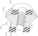
图5描绘适于与图1的扩张导管系统一起使用的示例性内窥镜的透视图;5 depicts a perspective view of an exemplary endoscope suitable for use with the dilatation catheter system of FIG. 1;
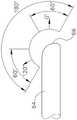
图6描绘图5的内窥镜的远侧端部的侧正视图,其示出示例性视角范围;6 depicts a side elevational view of the distal end of the endoscope of FIG. 5 illustrating an exemplary viewing angle range;
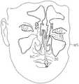
图7A描绘与上颌窦口相邻定位的图2B的引导导管的前视图;7A depicts a front view of the guide catheter of FIG. 2B positioned adjacent to the ostium of the maxillary sinus;
图7B描绘与上颌窦口相邻定位的图2B的引导导管的前视图,其中图2C的扩张导管和图2A的照明导丝被定位在引导导管中,并且导丝的远侧部分定位在上颌窦中;7B depicts a front view of the guide catheter of FIG. 2B positioned adjacent to the ostium of the maxillary antrum, wherein the dilation catheter of FIG. 2C and the illuminated guidewire of FIG. 2A are positioned in the guide catheter, and the distal portion of the guidewire is positioned in the maxillary Dou Zhong;
图7C描绘与上颌窦口相邻定位的图2B的引导导管的前视图,其中图2A的照明导丝相对于引导导管进一步朝远侧平移,并且到上颌窦中;7C depicts a front view of the guide catheter of FIG. 2B positioned adjacent to the ostium of the maxillary sinus, with the illuminated guidewire of FIG. 2A translated further distally relative to the guide catheter, and into the maxillary sinus;
图7D描绘与上颌窦口相邻定位的图2B的引导导管的前视图,图2C的扩张导管沿着图2A的照明导丝相对于引导导管朝远侧平移,以便将扩张导管的球囊定位在口内;7D depicts an anterior view of the guide catheter of FIG. 2B positioned adjacent to the ostium of the maxillary sinus, with the dilation catheter of FIG. 2C translated distally relative to the guide catheter along the illuminated guidewire of FIG. 2A to position the balloon of the dilation catheter in the mouth;
图7E描绘上颌窦口的前视图,其中口已通过使图7D的球囊充胀而扩大;Figure 7E depicts an anterior view of the maxillary sinus ostium, where the ostium has been enlarged by inflating the balloon of Figure 7D;
图8描绘另选的示例性引导导管的透视图;Figure 8 depicts a perspective view of an alternative exemplary guide catheter;
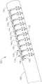
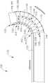
图9描绘图8的引导导管的远侧端部的透视图;9 depicts a perspective view of the distal end of the guide catheter of FIG. 8;
图10描绘图8的引导导管的远侧端部的另一个透视图;10 depicts another perspective view of the distal end of the guide catheter of FIG. 8;
图11描绘图8的引导导管的远侧端部的俯视平面图;11 depicts a top plan view of the distal end of the guide catheter of FIG. 8;
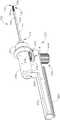
图12描绘附接至示例性引导导管柄部的图8的引导导管的透视图,两者均可以容易地结合到图1的示例性扩张导管系统中;12 depicts a perspective view of the guide catheter of FIG. 8 attached to an exemplary guide catheter handle, both of which can be easily incorporated into the exemplary dilatation catheter system of FIG. 1;
图13描绘附接至图12的引导导管柄部的图8的引导导管的另一个透视图;13 depicts another perspective view of the guide catheter of FIG. 8 attached to the guide catheter handle of FIG. 12;
图14描绘图8的引导导管和图12的引导导管柄部的分解透视图;14 depicts an exploded perspective view of the guide catheter of FIG. 8 and the guide catheter handle of FIG. 12;
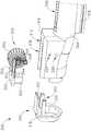
图15描绘图8的引导导管和图12的引导导管柄部的引导导管关节运动组件的分解透视图;15 depicts an exploded perspective view of the guide catheter articulation assembly of the guide catheter of FIG. 8 and the guide catheter handle of FIG. 12;
图16描绘图8的引导导管和图15的引导导管关节运动组件的平移组件的透视图;16 depicts a perspective view of the guide catheter of FIG. 8 and the translation assembly of the guide catheter articulation assembly of FIG. 15;
图17描绘图15的引导导管关节运动组件的旋转组件的透视图;17 depicts a perspective view of the rotation assembly of the guide catheter articulation assembly of FIG. 15;
图18描绘沿着图17的线18-18截取的图17的旋转组件的剖面透视图;18 depicts a cutaway perspective view of the rotary assembly of FIG. 17 taken along line 18-18 of FIG. 17;
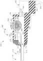
图19A描绘沿着图12的线19-19截取,附接至图12的示例性引导导管柄部的图8所示引导导管的剖面透视图,其中图15的引导导管关节运动组件处于第一位置;19A depicts a cutaway perspective view of the guide catheter of FIG. 8 attached to the exemplary guide catheter handle of FIG. 12 , taken along line 19-19 of FIG. 12 , with the guide catheter articulation assembly of FIG. 15 in a first position. Location;
图19B描绘沿着图12的线19-19截取,附接至图12的示例性引导导管柄部的图8的引导导管的剖面透视图,其中图15的引导导管关节运动组件处于第二位置;19B depicts a cutaway perspective view of the guide catheter of FIG. 8 attached to the exemplary guide catheter handle of FIG. 12 , taken along line 19-19 of FIG. 12 , with the guide catheter articulation assembly of FIG. 15 in a second position ;
图20A描绘图8的引导导管的远侧端部的侧正视图,其中引导导管处于直线、非关节运动构型;20A depicts a side elevational view of the distal end of the guide catheter of FIG. 8, wherein the guide catheter is in a rectilinear, non-articulating configuration;
图20B描绘图8的引导导管的远侧端部的侧正视图,其中引导导管处于弯曲、关节运动构型;20B depicts a side elevational view of the distal end of the guide catheter of FIG. 8, wherein the guide catheter is in a curved, articulating configuration;
图21描绘附接至另一示例性引导导管柄部的图8的引导导管的透视图,两者均可以容易地结合到图1的示例性扩张导管系统中;21 depicts a perspective view of the guide catheter of FIG. 8 attached to another exemplary guide catheter handle, both of which can be easily incorporated into the exemplary dilatation catheter system of FIG. 1;
图22描绘图21的引导导管柄部的分解透视图;22 depicts an exploded perspective view of the guide catheter handle of FIG. 21;
图23A描绘沿着图21的线23-23截取,附接至图21的引导导管柄部组件的图8的引导导管的剖面侧视图,其中该引导导管柄部组件的引导导管关节运动组件处于第一位置;23A depicts a cross-sectional side view of the guide catheter of FIG. 8 attached to the guide catheter handle assembly of FIG. 21 , taken along line 23-23 of FIG. 21 , with the guide catheter articulation assembly of the guide catheter handle assembly in first position;
图23B描绘沿着图21的线23-23截取,附接至图21的引导导管柄部组件的图8的引导导管的剖面透视图,其中图23A的引导导管关节运动组件处于第二位置;23B depicts a cutaway perspective view of the guide catheter of FIG. 8 attached to the guide catheter handle assembly of FIG. 21 , taken along line 23-23 of FIG. 21 , with the guide catheter articulation assembly of FIG. 23A in a second position;
图24描绘附接至另一示例性引导导管柄部的图8的引导导管的透视图,两者均可以容易地结合到图1的示例性扩张导管系统中;24 depicts a perspective view of the guide catheter of FIG. 8 attached to another exemplary guide catheter handle, both of which can be easily incorporated into the exemplary dilatation catheter system of FIG. 1;
图25描绘图24的引导导管柄部的分解透视图;25 depicts an exploded perspective view of the guide catheter handle of FIG. 24;
图26A描绘沿着图24的线26-26截取,附接至图24的引导导管柄部的图8的引导导管的剖面透视图,其中该引导导管柄部组件的引导导管关节运动组件处于锁定构型中的第一纵向位置;26A depicts a cutaway perspective view of the guide catheter of FIG. 8 attached to the guide catheter handle of FIG. 24 , taken along line 26-26 of FIG. 24 , with the guide catheter articulation assembly of the guide catheter handle assembly in a locked state. a first longitudinal position in the configuration;
图26B描绘沿着图24的线26-26截取,附接至图24的引导导管柄部的图8的引导导管的剖面透视图,其中图26A的引导导管关节运动组件处于解锁构型中的第一纵向位置;26B depicts a cutaway perspective view of the guide catheter of FIG. 8 attached to the guide catheter handle of FIG. 24 , taken along line 26-26 of FIG. 24 , with the guide catheter articulation assembly of FIG. 26A in an unlocked configuration. first longitudinal position;
图26C描绘沿着图24的线26-26截取,附接至图24的引导导管柄部的图8的引导导管的剖面透视图,其中图26A的引导导管关节运动组件处于解锁构型中的第二纵向位置;并且26C depicts a cutaway perspective view of the guide catheter of FIG. 8 attached to the guide catheter handle of FIG. 24 , taken along line 26-26 of FIG. 24 , with the guide catheter articulation assembly of FIG. 26A in an unlocked configuration. a second longitudinal position; and
图26D描绘沿着图24的线26-26截取,附接至图24的引导导管柄部的图8的引导导管的剖面透视图,其中图26A的引导导管关节运动组件处于锁定构型中的第二纵向位置。26D depicts a cutaway perspective view of the guide catheter of FIG. 8 attached to the guide catheter handle of FIG. 24 , taken along line 26-26 of FIG. 24 , with the guide catheter articulation assembly of FIG. 26A in a locked configuration. Second portrait position.
附图并非旨在以任何方式进行限制,并且能够设想本发明的各种实施方案可以多种其他方式来执行,包括那些未必在附图中描绘的方式。附图并入本说明书中并形成本说明书的一部分,示出了本发明的若干方面,并与本说明一起用于解释本发明的原理;然而,应当理解,本发明并不限于所示出的精确布置方式。The drawings are not intended to be limiting in any way, and it is contemplated that various embodiments of the invention may be carried out in numerous other ways, including those not necessarily depicted in the drawings. The accompanying drawings, which are incorporated in and form a part of this specification, illustrate several aspects of the invention and together with the description serve to explain the principles of the invention; however, it is to be understood that the invention is not limited to the illustrated Precise arrangement.
具体实施方式Detailed ways
下面对本发明的某些示例的说明不应用于限制本发明的范围。根据以举例的方式示出的以下描述,本发明的其他示例、特征、方面、实施方案和优点对于本领域的技术人员将是显而易见的,一种最佳方式被设想用于实施本发明。正如将会意识到的,本发明能够具有其他不同且明显的方面,这些方面均不脱离本发明。例如,虽然是各种各样的。因此,附图和描述事实上应被视为例示性的而非限制性的。The following description of certain examples of the invention should not be used to limit the scope of the invention. Other examples, features, aspects, embodiments and advantages of the invention will be apparent to those skilled in the art from the following description, shown by way of example, and a best mode is contemplated for carrying out the invention. As will be realized, the invention is capable of other different and obvious aspects, all without departing from the invention. For example, though various. Accordingly, the drawings and description are to be regarded as illustrative in nature and not restrictive.
应当理解,本文使用的术语“近侧”和“远侧”是相对于握持手持件组件的临床医生而言的。因此,端部执行器相对于近侧的手持件组件而言处于远侧。还应当理解,为方便和清晰起见,本文关于临床医生握持手持件组件的情况也使用空间术语诸如“顶部”和“底部”。然而,外科器械能够在许多取向和位置中使用,并且这些术语并非旨在为限制性的和绝对的。It should be understood that the terms "proximal" and "distal" as used herein are relative to a clinician holding the handpiece assembly. Thus, the end effector is distal relative to the proximal handpiece assembly. It should also be understood that spatial terms such as "top" and "bottom" are also used herein with respect to the clinician's grip of the handpiece assembly for convenience and clarity. However, surgical instruments can be used in many orientations and positions, and these terms are not intended to be limiting and absolute.
还应当理解,本文所述的教导内容、表达、型式、示例等中的任何一个或多个可与本文所述的其他教导内容、表达、型式、示例等中的任何一个或多个相结合。因此下述教导内容、表达、型式、示例等不应被视为相对于彼此隔离。参考本文的教导内容,本文的教导内容可进行组合的各种合适方式对于本领域的普通技术人员而言将显而易见。此类修改和变型旨在包括在权利要求书的范围内。It should also be understood that any one or more of the teachings, expressions, versions, examples, etc. described herein may be combined with any one or more of the other teachings, expressions, versions, examples, etc. described herein. The following teachings, expressions, versions, examples, etc. should therefore not be considered isolated with respect to each other. Various suitable ways in which the teachings herein may be combined will be apparent to those of ordinary skill in the art in view of the teachings herein. Such modifications and variations are intended to be included within the scope of the claims.
I.示例性扩张导管系统的概述I. Overview of Exemplary Dilatation Catheter Systems
图1示出示例性扩张导管系统(10),其可用于扩张鼻旁窦孔口;或用于扩张某一其他解剖通道(例如,在耳、鼻或喉内等)。此示例的扩张导管系统(10)包括扩张导管(20)、引导导管(30)、充胀器(40)以及导丝(50)。仅以举例的方式,扩张导管系统(10)可根据美国专利公布第2011/0004057号的教导内容中的至少一些来配置,其公开内容以引用方式并入本文。在一些型式中,扩张导管系统(10)的至少部分被配置成类似于由加利福尼亚州尔湾市(Irvine,California)的Acclarent公司提供的
如在图2C中最佳所见,扩张导管(20)的远侧端部(DE)包括可充胀扩张器(22)。扩张导管(20)的近侧端部(PE)包括握持部(24),该握持部具有侧向端口(26)和开口的近侧端部(28)。中空细长轴(18)从握持部朝远侧延伸。扩张导管(20)包括形成在轴(18)内的第一管腔(未示出),所述第一管腔在侧向端口(26)和扩张器(22)的内部之间提供流体连通。扩张导管(20)还包括形成在轴(18)内的第二管腔(未示出),所述第二管腔从开口的近侧端部(28)延伸到在扩张器(22)远侧的开口的远侧端部。该第二管腔被配置成以可滑动的方式接收导丝(50)。扩张导管(20)的第一管腔和第二管腔以流体方式彼此隔离。因此,扩张器(22)可通过以下方式选择性地充胀和收缩:在导丝(50)定位在第二管腔内时,经由侧向端口(26)沿着第一管腔传送流体。在一些型式中,扩张导管(20)被配置成类似于由加利福尼亚州尔湾市(Irvine,California)的Acclarent公司提供的Relieva
如在图2B中最佳所见,本示例的引导导管(30)包括在其远侧端部(DE)处的弯曲远侧部分(32)和在其近侧端部(PE)处的握持部(34)。握持部(34)具有开口的近侧端部(36)。引导导管(30)限定被配置成以可滑动的方式接收扩张导管(20)的管腔,使得引导导管(30)可通过弯曲的远侧端部(32)将扩张器(22)引出。在一些型式中,引导导管(30)被配置成类似于由加利福尼亚州尔湾市(Irvine,California)的Acclarent公司提供的Relieva
重新参照图1,本示例的充胀器(40)包括被配置成保持流体的筒体(42)和被配置成相对于筒体(42)往复运动的柱塞(44),以选择性地将流体从筒体(42)排出(或将流体抽吸到筒体中)。筒体(42)经由柔性管(46)与侧向端口(26)以流体方式耦合。因此,充胀器(40)能够操作以通过相对于筒体(42)平移柱塞(44)向扩张器(22)添加流体或者从扩张器(22)抽出流体。在本示例中,由充胀器(40)传送的流体包括盐水,但应当理解,可使用任何其他合适的流体。存在可用流体(例如,盐水等)填充充胀器(40)的各种方式。仅以举例的方式,在将柔性管(46)与侧向端口(26)耦合之前,可将柔性管(46)的远侧端部放置在容纳流体的贮存器中。然后可将柱塞(44)从远侧位置回缩到近侧位置,以将流体抽吸到筒体(42)中。随后可将充胀器(40)保持在筒体(42)的远侧端部向上指向的竖直位置中,并且随后可将柱塞(44)推进到中间或稍微远侧位置以便从筒体(42)清除任何空气。随后可将柔性管(46)的远侧端部与侧向端口(26)耦合。在一些型式中,充胀器(40)根据以下公布的教导内容中的至少一些来构造和操作:2014年3月13日公布的名称为“用于扩张解剖通道的充胀器(Inflator for Dilation ofAnatomical Passageway)”的美国公布第2014/0074141号,其公开内容以引用方式并入本文。Referring back to FIG. 1 , the inflator (40) of the present example includes a barrel (42) configured to hold a fluid and a plunger (44) configured to reciprocate relative to the barrel (42) to selectively Fluid is expelled from (or drawn into) the barrel (42). The barrel (42) is fluidly coupled to the side port (26) via a flexible tube (46). Thus, the inflator (40) is operable to add fluid to or withdraw fluid from the dilator (22) by translating the plunger (44) relative to the barrel (42). In this example, the fluid delivered by inflator (40) comprises saline, but it should be understood that any other suitable fluid may be used. There are various ways in which inflator (40) may be filled with fluid (eg, saline, etc.). By way of example only, prior to coupling flexible tube (46) with lateral port (26), the distal end of flexible tube (46) may be placed in a fluid-containing reservoir. Plunger (44) can then be retracted from the distal position to the proximal position to draw fluid into barrel (42). The inflator (40) can then be held in a vertical position with the distal end of the barrel (42) pointing upwards, and the plunger (44) can then be advanced to an intermediate or slightly distal position to remove the (42) Purge any air. The distal end of flexible tube (46) may then be coupled to lateral port (26). In some versions, the inflator (40) is constructed and operative in accordance with at least some of the teachings of the following publication: Inflator for Dilation of Anatomical Channels, published March 13, 2014 of Anatomical Passageway), the disclosure of which is incorporated herein by reference.
如图2A、图3和图4所示,本示例的导丝(50)包括围绕芯线(54)定位的线圈(52)。照明纤维(56)沿着芯线(54)的内部延伸并且终止在无创伤透镜(58)中。在导丝(50)的近侧端部处的连接器(55)能够实现在照明纤维(56)和光源(未示出)之间的光学耦合。照明纤维(56)可包括一个或多个光纤。当照明纤维(56)被光源照明时,透镜(58)被配置成投射光,使得照明纤维(56)将光从光源输送到透镜(58)。在一些型式中,导丝(50)的远侧端部比导丝(50)的近侧端部更具柔性。导丝(50)具有使得导丝(50)的远侧端部能够定位在扩张器(22)的远侧同时导丝(50)的近侧端部定位在握持部(24)的近侧的长度。导丝(50)可包括沿着其长度的至少一部分(例如,近侧部分)的标记,以向操作者提供指示导丝(50)相对于扩张导管(20)的插入深度的视觉反馈。仅以举例的方式,导丝(50)可根据美国公布第2012/0078118号的教导内容中的至少一些进行配置,其公开内容以引用方式并入本文。在一些型式中,导丝(50)被配置成类似于由加利福尼亚州尔湾市(Irvine,California)的Acclarent公司提供的Relieva Luma
II.示例性内窥镜的概述II. Overview of Exemplary Endoscopes
如上所述,在使用扩张导管系统(10)的过程期间,内窥镜(60)可用于在解剖通道内(例如,在鼻腔等内)提供可视化。如图4到图5所示,本示例的内窥镜包括主体(62)和从主体(62)朝远侧延伸的刚性的轴(64)。轴(64)的远侧端部包括弯曲的透明窗口(66)。多个棒状透镜和透光纤维可沿着轴(64)的长度延伸。透镜定位在棒状透镜的远侧端部处,并且摆动棱镜定位在透镜和窗口(66)之间。摆动棱镜可围绕横向于轴(64)的纵向轴线的轴线枢转。摆动棱镜限定随着摆动棱镜枢转的视线。所述视线限定相对于轴(64)的纵向轴线的视角。所述视线可从近似0度到近似120度,从近似10度到近似90度,或者在任何其他合适的范围内枢转。摆动棱镜和窗口(66)还提供跨越近似60度的视野(其中视线在视野中心)。因此,基于摆动棱镜的枢转范围,视野能够实现跨越近似180度、近似140度或任意其他范围的观察范围。当然,所有这些值只是示例。As noted above, endoscope (60) may be used to provide visualization within anatomical passages (eg, within nasal cavities, etc.) during procedures using dilation catheter system (10). As shown in FIGS. 4-5 , the endoscope of the present example includes a main body ( 62 ) and a rigid shaft ( 64 ) extending distally from the main body ( 62 ). The distal end of shaft (64) includes a curved transparent window (66). A plurality of rod lenses and light-transmitting fibers may extend along the length of the shaft (64). A lens is positioned at the distal end of the rod lens, and an oscillating prism is positioned between the lens and the window (66). The swing prism is pivotable about an axis transverse to the longitudinal axis of the shaft (64). The swing prism defines a line of sight that pivots with the swing prism. The line of sight defines a viewing angle relative to the longitudinal axis of the shaft (64). The line of sight may pivot from approximately 0 degrees to approximately 120 degrees, from approximately 10 degrees to approximately 90 degrees, or within any other suitable range. The swing prism and window (66) also provides a field of view spanning approximately 60 degrees (with the line of sight at the center of the field of view). Thus, the field of view enables a viewing range spanning approximately 180 degrees, approximately 140 degrees, or any other range based on the pivoting range of the swing prism. Of course, all these values are examples only.
本示例的主体(62)包括光柱(70)、目镜(72)、旋转转盘(74)以及枢轴转盘(76)。光柱(70)与轴(64)中的透光纤维通信,并且被配置成与光源耦合,以由此照明在窗口(66)远侧的患者体内的位点。目镜(72)被配置成经由内窥镜(60)的光学器件提供经由窗口(66)捕获的视图的可视化。应当理解,可视化系统(例如,照相机和显示屏等)可与目镜(72)耦合,以经由内窥镜(60)的光学器件提供经由窗口(66)捕获的视图的可视化。旋转转盘(74)被配置成围绕轴(64)的纵向轴线相对于主体(62)旋转轴(64)。应当理解,即使在摆动棱镜枢转成使得视线与轴(64)的纵向轴线非平行的情况下,仍可执行此旋转。枢转转盘(76)与摆动棱镜耦合,由此能够操作以围绕横向枢转轴线枢转摆动棱镜。主体(62)上的标记(78)提供指示视角的视觉反馈。参考本文的教导内容,可用于将旋转转盘(74)与摆动棱镜耦合的各种合适的部件和布置对于本领域的普通技术人员将是显而易见的。仅以举例的方式,内窥镜(60)可根据美国公布第2010/0030031号的教导内容中的至少一些进行配置,其公开内容以引用方式并入本文。参考本文的教导内容,内窥镜(60)可采用的其他合适的形式对于本领域的普通技术人员将是显而易见的。The main body ( 62 ) of this example includes a column of light ( 70 ), an eyepiece ( 72 ), a rotating dial ( 74 ), and a pivoting dial ( 76 ). A light column (70) communicates with the light-transmissive fiber in the shaft (64) and is configured to be coupled with a light source to thereby illuminate a site within the patient's body distal to the window (66). Eyepiece (72) is configured to provide, via the optics of endoscope (60), visualization of the view captured via window (66). It should be appreciated that a visualization system (eg, camera and display screen, etc.) may be coupled with eyepiece (72) to provide visualization of the view captured via window (66) via the optics of endoscope (60). The rotating dial (74) is configured to rotate the shaft (64) relative to the body (62) about the longitudinal axis of the shaft (64). It will be appreciated that this rotation can be performed even with the swing prism pivoted such that the line of sight is non-parallel to the longitudinal axis of the shaft (64). A pivot dial (76) is coupled to the swing prism and is thereby operable to pivot the swing prism about a transverse pivot axis. Markings (78) on the body (62) provide visual feedback indicating the viewing angle. Various suitable components and arrangements that may be used to couple the rotating carousel (74) with the oscillating prism will be apparent to those of ordinary skill in the art in view of the teachings herein. By way of example only, endoscope (60) may be configured in accordance with at least some of the teachings of US Publication No. 2010/0030031, the disclosure of which is incorporated herein by reference. Other suitable forms that endoscope (60) may take will be apparent to those of ordinary skill in the art in view of the teachings herein.
III.用于扩张上颌窦口的示例性方法III. Exemplary method for dilating the ostium of the maxillary sinus
图7A至图7E示出了使用上面讨论的扩张导管系统(10)扩张患者的上颌窦(MS)的窦口(O)的示例性方法。虽然在扩张上颌窦(MS)的窦口(O)的上下文中提供本示例,但应当理解,扩张导管系统(10)可用于各种其他手术中。仅以举例的方式,扩张导管系统(10)及其变型可用于扩张扩张咽鼓管、喉、鼻后孔、蝶窦口、与一个或多个筛窦空气细胞相关联的一个或多个开口、额隐窝和/或与鼻旁窦相关联的其他通道。参考本文的教导内容,可使用扩张导管系统(10)的其他合适的方式对于本领域的普通技术人员将是显而易见的。7A-7E illustrate an exemplary method of dilating the ostium (O) of a patient's maxillary sinus (MS) using the dilation catheter system (10) discussed above. While the present example is provided in the context of dilating the ostium (O) of the maxillary sinus (MS), it should be understood that dilation catheter system (10) may be used in a variety of other procedures. By way of example only, the dilation catheter system (10) and variations thereof may be used to dilate the Eustachian tube, larynx, retronasal ostium, sphenoid ostium, one or more openings associated with one or more ethmoid air cells , frontal recesses, and/or other channels associated with the paranasal sinuses. Other suitable ways in which dilatation catheter system (10) may be used will be apparent to those of ordinary skill in the art in view of the teachings herein.
在本示例的手术中,引导导管(30)可经鼻插入并且推进穿过鼻腔(NC)到达待扩张的目标解剖通道即在窦口(O)内或附近的位置,如图7A所示。在此阶段,可充胀扩张器(22)和导丝(50)的远侧端部可定位在引导导管(30)的弯曲远侧端部(32)内或近侧。引导导管(30)的此定位可用内窥镜(例如上述内窥镜(60))和/或通过直接可视化、射线照相和/或通过任何其他合适的方法进行内窥镜检查。在已经定位引导导管(30)之后,操作者可将导丝(50)朝远侧推进穿过引导导管(30),使得导丝(50)的远侧部分穿过上颌窦(MS)的口(O)并且进入上颌窦(MS)的腔,如图7B和图7C所示。操作者可照亮照明纤维(56)和透镜(58),这可提供透过患者的面部的经皮照明以使操作者能够相对容易地在视觉上确认导丝(50)的远侧端部定位在上颌窦(MS)中。In the present example procedure, a guide catheter (30) may be inserted nasally and advanced through the nasal cavity (NC) to a location within or near the target anatomical passage to be dilated, ie, the ostium (O), as shown in FIG. 7A . At this stage, the inflatable dilator ( 22 ) and the distal end of the guide wire ( 50 ) can be positioned within or proximal to the curved distal end ( 32 ) of the guide catheter ( 30 ). This positioning of guide catheter (30) may be endoscopically inspected with an endoscope, such as endoscope (60) described above, and/or by direct visualization, radiography, and/or by any other suitable method. After the guide catheter (30) has been positioned, the operator may advance the guide wire (50) distally through the guide catheter (30) so that the distal portion of the guide wire (50) passes through the ostium of the maxillary sinus (MS) (O) and into the cavity of the maxillary sinus (MS), as shown in Figure 7B and Figure 7C. The operator can illuminate the illumination fiber (56) and lens (58), which can provide percutaneous illumination through the patient's face to allow the operator to relatively easily visually confirm the distal end of the guidewire (50) Localized in the maxillary sinus (MS).
如图7C所示,在引导导管(30)和导丝(50)合适定位的情况下,扩张导管(20)沿着导丝(50)推进并且穿过引导导管(30)的弯曲远侧端部(32),其中扩张器(22)处于非扩张状态,直到扩张器(22)定位在上颌窦(MS)的口(O)(或某一其他目标解剖通道)内。在扩张器(22)已经定位在口(O)内之后,可使扩张器(22)充胀,由此使口(O)扩张,如图7D所示。为了使扩张器(22)充胀,可致动柱塞(44)以通过扩张导管(20)将盐水从充胀器(40)的筒体(42)推动到扩张器(22)中。流体的输送使扩张器(22)膨胀到膨胀状态以诸如通过重塑骨等打开或扩张口(O),形成口(O)。仅以举例的方式,可将扩张器(22)充胀到尺寸适于达到约10个大气压到约12个大气压的体积。扩张器(22)可保持在该体积下持续几秒以充分打开口(O)(或其它目标解剖通道)。随后可通过使充胀器(40)的柱塞(44)反向以将盐水带回到充胀器(40)来使扩张器(22)返回到非膨胀状态。扩张器(22)可在不同口和/或其它目标解剖通道中重复地充胀和收缩。然后,可将扩张导管(20)、导丝(50)以及引导导管(30)从患者身上移除,如图7E所示。As shown in FIG. 7C , with guide catheter ( 30 ) and guide wire ( 50 ) properly positioned, dilation catheter ( 20 ) is advanced along guide wire ( 50 ) and through the curved distal end of guide catheter ( 30 ). portion (32), wherein the dilator (22) is in a non-expanded state until the dilator (22) is positioned within the ostium (O) (or some other target anatomical passage) of the maxillary sinus (MS). After the dilator (22) has been positioned within the port (O), the dilator (22) can be inflated, thereby dilating the port (O), as shown in Figure 7D. To inflate dilator ( 22 ), plunger ( 44 ) can be actuated to push saline from barrel ( 42 ) of inflator ( 40 ) into dilator ( 22 ) through dilation catheter ( 20 ). Delivery of the fluid expands the dilator (22) to an expanded state to open or dilate the opening (O), such as by remodeling bone, forming the opening (O). By way of example only, dilator (22) may be inflated to a volume sized to achieve a pressure of about 10 atmospheres to about 12 atmospheres. The dilator (22) can be held at this volume for several seconds to fully open the ostium (O) (or other targeted anatomical passage). The dilator ( 22 ) can then be returned to the non-inflated state by reversing the plunger ( 44 ) of the inflator ( 40 ) to bring saline back into the inflator ( 40 ). Dilator (22) can be repeatedly inflated and deflated in different ostia and/or other targeted anatomical passages. Dilation catheter (20), guide wire (50) and guide catheter (30) may then be removed from the patient, as shown in Figure 7E.
在一些情况下,可能期望在扩张导管(20)已经用于扩张口(O)之后冲洗窦和鼻侧腔。可执行此冲洗来冲掉可能在扩张手术之后存在的血液等。例如,在一些情况下,可允许引导导管(30)在移除导丝(50)和扩张导管(20)之后保持就位,并且可通过引导导管(30)来传递灌洗液、其他物质或一个或多个其他装置(例如,冲洗导管、球囊导管、切割球囊、刀具、切削器(chompers)、旋转刀具、旋转钻头、旋转刀片、顺序扩张器、锥形扩张器、冲头、解剖器、锉刀、非充胀机械可膨胀构件、高频机械振动器、扩张支架以及射频消融装置、微波消融装置、激光装置、圈套、活检工具、窥视器(scopes)和递送诊断剂或治疗剂的装置)以进一步治疗病症。仅以举例的方式,冲洗可根据以下专利的教导内容中的至少一些来实施:2009年12月8日公布的名称为“用于治疗和/或诊断耳、鼻和喉的疾病的方法、装置和系统(Methods,Devices and Systems for Treatment and/or Diagnosis of Disorders ofthe Ear,Nose and Throat)”的美国专利第7,630,676号,其公开内容以引用方式并入本文。可通过引导导管(30)进给以在移除扩张导管(20)之后到达冲洗位点的冲洗导管的示例是由加利福尼亚州尔湾市(Irvine,California)的Acclarent公司提供的Relieva

IV.具有远侧关节运动组件的示例性另选的引导导管IV. Exemplary Alternative Guide Catheters with Distal Articulation Assembly
如上所述,引导导管(30)在其远侧端部(DE)处包括弯曲远侧部分(32)。弯曲远侧部分(32)可以被配置成当经鼻插入并且推进穿过患者鼻腔(NC)时,进入特定的窦口(O)。此外,引导导管(30)的弯曲远侧部分(32)可能需要足够的刚性,使得在插入和推进引导导管(30)期间,当操作者向远侧端部(DE)施加力时,引导导管(30)保持其纵向轮廓。由于引导导管(30)包括预先确定的弯曲远侧部分(32),因此在手术期间如果操作者希望接近患者内的各种鼻腔/窦腔,操作者可能需要使用具有各种弯曲远侧部分(32)的多个引导导管(30)。目前,操作者可以通过移除具有第一弯曲远侧部分(32)的第一引导导管(30),并且用第二引导导管替换第一引导导管(30)以接近在鼻腔(NC)内的各种期望位置,其中所述第二引导导管具有适于接近在鼻腔(NC)内的特定位置的不同弯曲远侧部分。As mentioned above, the guide catheter (30) comprises at its distal end (DE) a curved distal portion (32). The curved distal portion (32) may be configured to enter a specific ostium (O) when inserted nasally and advanced through the patient's nasal cavity (NC). Furthermore, the curved distal portion (32) of the guide catheter (30) may need to be sufficiently rigid so that when the operator applies force to the distal end (DE) during insertion and advancement of the guide catheter (30), the guide catheter (30) maintains its longitudinal profile. Since the guide catheter (30) includes a predetermined curved distal portion (32), if the operator wishes to access various nasal/sinus cavities within the patient during surgery, the operator may need to use a catheter with various curved distal portions (32). 32) a plurality of guide catheters (30). Currently, the operator can access the nasal cavity (NC) by removing the first guide catheter (30) having the first curved distal portion (32), and replacing the first guide catheter (30) with a second guide catheter. Various desired locations, wherein the second guide catheter has a differently curved distal portion adapted to approach a particular location within the nasal cavity (NC).
因此,可能期望将引导导管的远侧端部从由引导导管的其余部分限定的纵向轴线关节运动/弯曲,同时仍保持适当刚性,以便接近在鼻腔(NC)内的各个位置而无需手动更换引导导管(30)。在扩张手术期间,在引导导管的远侧端部与目标区域相邻时,还可期望以不同角度选择性地关节运动/弯曲引导导管的远侧端部。换句话讲,在引导导管在患者的解剖通道内时,可能期望弯曲引导导管的远侧端部。在手术期间选择性地关节运动/弯曲引导导管的远侧端部可在患者的鼻腔内提供更好的导向能力,允许操作者更容易地将扩张器定位在目标区域内。例如,在导管处于直线构型时,操作者可首先将导管插入患者的鼻腔中;然后在将导管定位在患者的鼻腔中之后弯曲导管的远侧端部。可以选择性地定制弯曲角度,以便于接近与特定鼻旁窦腔相关联的引流通道。例如,操作者可以选择性地调整弯曲角度以接近与额窦、上颌窦、蝶窦或筛窦相关联的引流通道。以下是与具有远侧关节运动/弯曲特征结构的各种合适的柄部耦合的示例性引导导管,所述特征结构被配置成偏转引导导管的远侧端部,同时保持足够的刚性,使得弯曲的远侧端部在适当使用引导导管期间抵抗不期望的弯曲。此外,在引导导管定位于患者内的与目标区域相邻时,柄部可关节运动/弯曲引导导管。Therefore, it may be desirable to articulate/bend the distal end of the guide catheter from the longitudinal axis defined by the remainder of the guide catheter while still maintaining adequate rigidity to allow access to various locations within the nasal cavity (NC) without manual replacement of the guide catheter. Catheter (30). During dilation procedures, it may also be desirable to selectively articulate/bend the distal end of the guide catheter at different angles as it is adjacent to the target area. In other words, it may be desirable to bend the distal end of the guide catheter while the guide catheter is within the patient's anatomical passage. Selective articulation/bending of the distal end of the guide catheter during surgery may provide better guidance capability within the patient's nasal cavity, allowing the operator to more easily position the dilator within the target area. For example, the operator may first insert the catheter into the patient's nasal cavity when the catheter is in a straight configuration; then bend the distal end of the catheter after positioning the catheter in the patient's nasal cavity. The angle of curvature can be selectively tailored to facilitate access to drainage channels associated with specific paranasal sinus cavities. For example, the operator may selectively adjust the bending angle to access drainage channels associated with the frontal, maxillary, sphenoid, or ethmoid sinuses. The following are exemplary guide catheters coupled with various suitable handles having distal articulation/bending features configured to deflect the distal end of the guide catheter while maintaining sufficient rigidity to allow bending The distal end of the guide catheter resists undesired bending during proper use of the guide catheter. In addition, the handle is articulateable/flexible to guide the catheter while the guide catheter is positioned within the patient adjacent to the target area.
图8至图11示出了具有进行关节运动的远侧部分(130)的示例性引导导管(100),该进行关节运动的远侧部分可附接至各种引导导管柄部(200,300,400),使得引导导管(100)和选定的引导导管柄部(200,300,400)可以容易地结合到扩张导管系统(10)中作为对引导导管(30)的替换。引导导管(100)包括进行关节运动的远侧部分(130)、延伸至进行关节运动的远侧部分(130)中的近侧部分(110),以及从进行关节运动的远侧部分(130)朝向开口的近侧端部(112)延伸的一对牵拉线(120)。如将在下文中更详细地描述的,牵拉线(120)耦合在进行关节运动的远侧部分(130)的远侧端部附近,同时牵拉线(120)被配置成相对于近侧部分(110)平移,以便选择性地使进行关节运动的远侧部分(130)进行关节运动/弯曲。8-11 illustrate an exemplary guide catheter (100) having an articulating distal portion (130) attachable to various guide catheter handles (200, 300, 400), This allows guide catheter (100) and selected guide catheter handle (200, 300, 400) to be easily incorporated into dilation catheter system (10) as a replacement for guide catheter (30). Guide catheter (100) includes articulating distal portion (130), proximal portion (110) extending into articulating distal portion (130), and A pair of puller wires (120) extend toward the open proximal end (112). As will be described in more detail below, puller wire (120) is coupled near the distal end of articulating distal portion (130), while puller wire (120) is configured relative to the proximal portion (110) translates to selectively articulate/bend the articulating distal portion (130).
近侧部分(110)包括刚性的轴(114),所述刚性的轴朝近侧终止于开口的近侧端部(112)。进行关节运动的远侧部分(130)包括连接至刚性的轴(114)的远侧端部的刚性的部分(150),从刚性的部分(150)朝远侧延伸的进行关节运动的肋(140)的线性阵列,以及从进行关节运动的肋(140)的最远侧线性阵列延伸的远侧肋(160)。尽管当前示例具有耦合到进行关节运动的远侧部分(130)的刚性的部分(150)的刚性的轴(114),但应当理解,这些可以整体附接或分成更多部分。远侧肋(160)包括开口的远侧端部(132)。管腔从开口的近侧端部(112)一直延伸到开口的远侧端部(132)。管腔被配置成可滑动地接纳扩张导管(20),使得引导导管(100)可在开口的近侧端部(112)处接纳扩张导管(20),并且使得引导导管(100)可将扩张器(220)导出通过开口的远侧端部(132)。The proximal portion (110) includes a rigid shaft (114) that terminates proximally in an open proximal end (112). The articulating distal portion (130) includes a rigid portion (150) connected to the distal end of the rigid shaft (114), from which extends distally an articulating rib ( 140), and a distal rib (160) extending from the most distal linear array of articulating ribs (140). Although the current example has the rigid shaft (114) coupled to the rigid portion (150) of the articulating distal portion (130), it should be understood that these could be attached as one piece or divided into more parts. Distal rib (160) includes an open distal end (132). The lumen extends from the open proximal end (112) to the open distal end (132). The lumen is configured to slidably receive dilation catheter (20), such that guide catheter (100) can receive dilation catheter (20) at open proximal end (112), and such that guide catheter (100) can dilate The distal end (132) of the device (220) exits through the opening.
如在图10中最佳所见,弹性脊(170)沿着进行关节运动的远侧部分(130)的底部延伸以连接刚性的部分(150)、进行关节运动的肋(140)的线性阵列和远侧肋(160)。换句话讲,弹性脊(170)充当弹性活动铰链,以连接刚性的部分(150)、进行关节运动的肋(140)的线性阵列和远侧肋(160)。如将在下面更详细地描述的,响应于牵拉线(120)的平移,弹性脊(170)适应远侧肋(160)和进行关节运动的肋(140)相对于刚性的部分(150)的关节运动。As best seen in FIG. 10, elastic ridges (170) extend along the bottom of articulating distal portion (130) to connect rigid portion (150), a linear array of articulating ribs (140). and distal rib (160). In other words, elastic spine (170) acts as an elastic living hinge to connect rigid portion (150), linear array of articulating ribs (140), and distal rib (160). As will be described in more detail below, elastic spine (170) accommodates distal rib (160) and articulating rib (140) relative to rigid portion (150) in response to translation of puller wire (120). joint movement.
刚性的部分(150)的远侧端部包括远侧表面(158),并且限定了顶部线性朝远侧呈现的凹坑(153)和一对侧面拱形朝远侧呈现的凹坑(155)。每个进行关节运动的肋(140)包括顶部线性朝近侧呈现的突起(142)、一对侧面拱形朝近侧呈现的突起(144)、近侧成角度的表面(146)和远侧成角度的表面(148)。此外,每个进行关节运动的肋(140)限定了顶部线性朝远侧呈现的凹坑(143)和一对侧面拱形朝远侧呈现的凹坑(145)。远侧肋(160)包括顶部线性朝近侧呈现的突起(162)、一对侧面拱形朝近侧呈现的突起和近侧表面(166)。此外,远侧肋(160)还限定了一对牵拉线耦合孔(168)。牵拉线(120)的远侧端部可以经由牵拉线耦合孔(168)与远侧肋(160)耦合。The distal end of the rigid portion (150) includes a distal surface (158) and defines a top linear distally presenting dimple (153) and a pair of side arched distally presenting dimples (155) . Each articulating rib (140) includes a top linearly proximally presenting protrusion (142), a pair of side arched proximally presenting protrusions (144), a proximally angled surface (146) and a distal Angled Surfaces (148). In addition, each articulating rib (140) defines a top linear distally presenting dimple (143) and a pair of side arched distally presenting dimples (145). Distal rib (160) includes a top linear proximally presenting protrusion (162), a pair of lateral arched proximally presenting protrusions and a proximal surface (166). Additionally, distal rib (160) defines a pair of puller wire coupling holes (168). The distal end of puller wire (120) may be coupled to distal rib (160) via puller wire coupling hole (168).
在进行关节运动的远侧部分(130)的关节运动期间,远侧肋(160)的朝近侧呈现的突起(162,164)被配置成分别在最远侧进行关节运动的肋(140)的朝远侧呈现的凹坑(143,145)内滑动。类似地,在进行关节运动的远侧部分(130)的关节运动期间,最近侧进行关节运动的肋(140)的朝近侧呈现的突起(142,144)被配置成分别在刚性的部分(150)的朝远侧呈现的凹坑(153,155)内滑动。在进行关节运动的远侧部分(130)的关节运动期间,在最远侧和最近侧的肋(140)之间的每个进行关节运动的肋(140)的朝近侧呈现的突起(142,144)被配置成分别在相邻的朝远侧呈现的凹坑(143,145)内滑动。During articulation of the distal portion (130) that is articulating, the proximally-facing protrusions (162, 164) of the distal rib (160) are configured to align with the proximally-facing protrusions (164) of the most distally articulating rib (140), respectively. slides within the dimples (143, 145) present distally. Similarly, during articulation of the articulating distal portion (130), the proximally-facing protrusions (142, 144) of the most proximally articulating rib (140) are configured to abut rigid portions (150) respectively. sliding in the distally presented dimples (153, 155). During articulation of the articulating distal portion (130), the proximally-facing protrusions (142, 144) of each articulating rib (140) between the most distal and proximal-most ribs (140) ) are configured to slide within adjacent distally presenting pockets (143, 145), respectively.
在直线构型和关节运动构型两者中,拱形朝近侧呈现的突起(144,164)可以至少部分地容纳在对应的凹坑(145,155)内。然而,在初始处于直线构型时,顶部线性朝近侧呈现的突起(142,162)可不容纳在对应的凹坑(143,153)内,但在处于关节运动构型中时,可容纳在对应的凹坑(143,153)内。然而,这种布置仅仅是可选的,因为在直线构型中,所有突起(142,144,162,164)可以部分地容纳在对应的凹坑(143,145,153,155)内;在直线构型中,无突起(142,144,162,164)可以部分地容纳在对应的凹坑(143,145,153,155)内;或者基于远侧部分(130)的关节运动状态,可以使用对应凹坑(143,145,153,155)内的外壳突起(142,144,162,164)的任何其他合适的组合/图案,如本领域的普通技术人员参考本文的教导内容将显而易见的。In both the rectilinear configuration and the articulating configuration, the arcuate proximally presented protrusions (144, 164) may be at least partially received within corresponding recesses (145, 155). However, the top linearly proximally presenting protrusions (142, 162) may not be received within the corresponding recesses (143, 153) when initially in the rectilinear configuration, but may be received within the corresponding recesses when in the articulating configuration Within (143,153). However, this arrangement is only optional, as in a rectilinear configuration all protrusions (142, 144, 162, 164) may be partially accommodated within corresponding recesses (143, 145, 153, 155); in a rectilinear configuration, no protrusions (142, 144, 162, 164) may be partially or any other suitable combination/pattern of housing protrusions (142, 144, 162, 164) within corresponding recesses (143, 145, 153, 155) may be used based on the articulation state of the distal portion (130), such as These will be apparent to those of ordinary skill in the art in view of the teachings herein.
在朝近侧呈现的突起(142,144,162,164)与对应凹坑(143,145,153,155)之间的相互作用可有助于在引导导管(100)的插入期间促进足够的刚性。例如,突起(144,164)和凹坑(145,155)的拱形轮廓可以避免响应于施加在引导导管(130)上的外力,意外地使远侧部分(130)进行关节运动。除非施加在引导导管(100)上的力分布对应于突起(144,164)和凹坑(145,155)的拱形轮廓,否则由在突起(144,164)与凹坑(145,155)之间的相互作用提供的摩擦制动力可阻止引导导管(100)的不期望的关节运动。换句话讲,突起(144,164)和凹坑(145,155)的拱形轮廓可能需要沿外力方向的特定且一致的改变,以操纵进行关节运动的远侧部分(130)进行关节运动/弯曲。应当理解,牵拉线(120)的平移可被配置成沿力方向提供这种一致和恒定的变化,以关节运动/弯曲引导导管(100)。The interaction between the proximally presented protrusions (142, 144, 162, 164) and corresponding dimples (143, 145, 153, 155) may help promote sufficient rigidity during insertion of guide catheter (100). For example, the arcuate profile of protrusions (144, 164) and dimples (145, 155) may prevent inadvertent articulation of distal portion (130) in response to an external force exerted on guide catheter (130). The friction provided by the interaction between protrusions (144, 164) and dimples (145, 155) The braking force can prevent undesired articulation of guide catheter (100). In other words, the arcuate profile of the protrusions (144, 164) and dimples (145, 155) may require specific and consistent changes in the direction of the external force to manipulate the articulating distal portion (130) for articulation/bending. It should be appreciated that translation of puller wire (120) may be configured to provide such a consistent and constant change in force direction to articulate/bend guide catheter (100).
如上所述,每个进行关节运动的肋(140)包括近侧成角度的表面(146)和远侧成角度的表面(148),而远侧肋(160)包括近侧表面(166),并且刚性的部分(150)包括远侧表面(158)。在进行关节运动的远侧部分(130)的关节运动期间,近侧成角度表面(146,166)被配置成邻接对应且相邻的远侧成角度表面(148,158),使得当进行关节运动的远侧部分(130)完全进行关节运动时,近侧成角度表面(146,166)与对应且相邻的远侧成角度表面(148,158)齐平。成角度表面(146,148,158,166)之间的相互作用可有助于响应于牵拉线(120)的平移促进关节运动。此外,成角度表面(146,148,158,166)的相互作用可有助于形成由进行关节运动的远侧部分(130)限定的光滑内管腔,以帮助适应扩张器(22)在管腔内的纵向平移。As noted above, each articulating rib (140) includes a proximal angled surface (146) and a distal angled surface (148), while the distal rib (160) includes a proximal surface (166), And rigid portion (150) includes a distal surface (158). During articulation of the articulating distal portion (130), the proximal angled surfaces (146, 166) are configured to abut corresponding and adjacent distal angled surfaces (148, 158) such that when the articulating distal When portion (130) is fully articulated, proximal angled surfaces (146, 166) are flush with corresponding and adjacent distal angled surfaces (148, 158). The interaction between the angled surfaces (146, 148, 158, 166) can help facilitate joint motion in response to translation of the puller wire (120). In addition, the interaction of angled surfaces (146, 148, 158, 166) can help create a smooth inner lumen defined by articulating distal portion (130) to help accommodate longitudinal translation of dilator (22) within the lumen.
虽然在当前示例中,牵拉线(120)沿着引导导管(100)的外部延伸,但应当理解,这仅仅是可选的。牵拉线(120)可在预定义的独立管腔,或者如本领域的普通技术人员参考本文的教导内容将显而易见的任何其他合适的布置内,沿着引导导管(100)内部的引导导管延伸,其中所述独立管腔的尺寸被设计成可滑动地容纳牵拉线(120)。While in the present example puller wire (120) extends along the exterior of guide catheter (100), it should be understood that this is merely optional. Puller wire (120) may extend along the guide catheter inside guide catheter (100) within a predefined separate lumen, or any other suitable arrangement as will be apparent to those of ordinary skill in the art in view of the teachings herein. , wherein the separate lumen is sized to slidably accommodate a puller wire (120).
图12至图14示出了耦合到示例性引导导管柄部(200)的引导导管(100),使得这两者可以容易地结合到上述扩张导管系统(10)中,代替引导导管(30)。引导导管柄部(200)包括近侧细长主体(202)、沿着近侧细长主体(202)的底部延伸的T形导轨(204)、在相对于近侧细长主体(202)的上方和远侧的导管外壳(206)、关节运动外壳(210)和引导导管关节运动组件(220)。如将在下面更详细地描述的,引导导管关节运动组件(220)与牵拉线(120)的近侧端部可操作地耦合,使得引导导管关节运动组件(220)可相对于刚性的轴(114)平移拉线(120)。如上所述,并且如下面将进一步描述的,牵拉线(120)的平移可驱动进行关节运动的远侧部分(130)的关节运动。另外,如将在下面更详细地描述的,引导导管关节运动组件(220)可以被配置成选择性地保持牵拉线(120)相对于刚性的轴(114)的纵向位置,以便维持关节运动远侧部分(130)的关节运动构型。Figures 12 to 14 illustrate guide catheter (100) coupled to an exemplary guide catheter handle (200) such that the two can be easily incorporated into dilation catheter system (10) described above in place of guide catheter (30) . The guide catheter handle (200) includes a proximal elongated body (202), a T-shaped rail (204) extending along the bottom of the proximal elongated body (202), Superior and distal catheter housing (206), articulation housing (210) and guide catheter articulation assembly (220). As will be described in more detail below, guide catheter articulation assembly (220) is operably coupled to the proximal end of puller wire (120) such that guide catheter articulation assembly (220) can be moved relative to a rigid shaft (114) translational stay wire (120). As noted above, and as will be further described below, translation of puller wire (120) may drive articulation of articulating distal portion (130). Additionally, as will be described in greater detail below, guide catheter articulation assembly (220) may be configured to selectively maintain the longitudinal position of puller wire (120) relative to rigid shaft (114) in order to maintain articulation Articulation configuration of distal portion (130).
T形导轨(204)的尺寸可以被设计为选择性地与柄部延伸部(诸如包括指钉的柄部延伸部)耦合,以促进用单手抓持器械。近侧细长主体(202)可与第一可滑动主体和第二可滑动主体可滑动地耦合,该第一可滑动主体与扩张导管(20)可操作地连接,并且该第二可滑动主体与导丝(50)可操作地耦合。因此,操作者可相对于细长主体(202)平移和/或旋转第一主体和第二主体,以便相对于引导导管柄部(200)和引导导管(100)两者平移和/或旋转扩张导管(20)或导丝(50)。当根据以上描述适当地耦合在一起时,操作者可以用单手操纵扩张导管(20)、导丝(50)以及引导导管(100)。T-rail (204) may be sized to selectively couple with a handle extension, such as a handle extension including a fingertip, to facilitate grasping the instrument with one hand. The proximal elongated body (202) is slidably coupled with a first slidable body operatively connected to the dilation catheter (20) and a second slidable body Operably coupled with a guidewire (50). Accordingly, the operator can translate and/or rotate the first and second bodies relative to the elongate body (202) to translate and/or rotate the dilation relative to both the guide catheter handle (200) and the guide catheter (100). Catheter (20) or guidewire (50). When properly coupled together as described above, the operator can manipulate dilation catheter (20), guide wire (50), and guide catheter (100) with a single hand.
刚性的轴(114)从关节运动外壳(210)朝远侧延伸并被固定到该关节运动外壳。关节运动外壳(210)和导管外壳(206)限定了被配置成可滑动地接纳扩张导管(20)的通路(208),使得扩张导管(20)可以插穿通路(208)以便插穿由引导导管(100)限定的管腔。Rigid shaft (114) extends distally from articulation housing (210) and is secured to the articulation housing. Articulation housing (210) and catheter housing (206) define passageway (208) configured to slidably receive dilation catheter (20) such that dilation catheter (20) may be inserted through passageway (208) for insertion by a guide A lumen defined by catheter (100).
关节运动外壳(210)还限定了开口(212)和通孔(214)以选择性地容纳引导导管关节运动组件(220)的部分。引导导管关节运动组件(220)包括第一旋转组件(230)、第二旋转组件(250)和平移组件(280)。如将在下面更详细地描述的,第一旋转组件(230)被配置成旋转第二旋转组件(250);同时第二旋转组件(250)被配置成平移平移组件(280)以便相对于刚性的轴(114)纵向平移牵拉线(120),并由此使进行关节运动的远侧部分(130)进行关节运动/弯曲。Articulation housing (210) also defines opening (212) and throughbore (214) to selectively receive a portion of guide catheter articulation assembly (220). The guide catheter articulation assembly (220) includes a first rotation assembly (230), a second rotation assembly (250), and a translation assembly (280). As will be described in more detail below, the first rotational assembly (230) is configured to rotate the second rotational assembly (250); while the second rotational assembly (250) is configured to translate the translational assembly (280) relative to the rigid Axis (114) of the puller longitudinally translates puller wire (120) and thereby articulates/bends articulating distal portion (130).
第一旋转组件(230)包括可旋转握持部(232)、轴(234)和具有多个齿(238)的第一锥齿轮(236)。轴(234)可旋转地设置在通孔(214)内,同时第一锥齿轮(236)可旋转地容纳在开口(212)内。可旋转握持部(232)、轴(234)和第一锥齿轮(236)整体连接,使得可旋转握持部(232)的旋转导致轴(234)和第一锥齿轮(236)的旋转。可旋转握持部(232)在关节运动外壳(210)的限定通孔(214)的部分的下方延伸。可旋转握持部(232)被定位成使得操作者能够用一只手抓持引导导管柄部(200)。因此,操作者可以使可旋转握持部(232)围绕第一轴线(A1)相对于关节运动外壳(210)旋转,以便使轴(234)和第一锥齿轮(236)也围绕第一轴线(A1)相对于关节运动外壳(210)旋转。A first rotating assembly (230) includes a rotatable grip (232), a shaft (234), and a first bevel gear (236) having a plurality of teeth (238). A shaft (234) is rotatably disposed within the through hole (214), while a first bevel gear (236) is rotatably received within the opening (212). The rotatable grip (232), shaft (234) and first bevel gear (236) are integrally connected such that rotation of the rotatable grip (232) causes rotation of the shaft (234) and first bevel gear (236) . A rotatable grip (232) extends below the portion of the articulation housing (210) defining the throughbore (214). Rotatable grip (232) is positioned to enable an operator to grasp guide catheter handle (200) with one hand. Accordingly, an operator may rotate rotatable grip (232) about first axis (A1) relative to articulation housing (210) such that shaft (234) and first bevel gear (236) also about first axis (A1) rotates relative to the articulation housing (210).
第二旋转组件(250)包括设置在两个垫圈(252)之间的第二锥齿轮(256),所有这些都被容纳在由关节运动外壳(210)限定的室(216)内。第二锥齿轮(256)可旋转地容纳在室(216)内,使得第二锥齿轮(256)可围绕第二轴线(A2)相对于关节运动外壳组件(210)旋转。第二锥齿轮(256)包括被配置成与第一锥齿轮(236)的齿(238)互补啮合的多个齿(258)。因此,第一锥齿轮(236)围绕第一轴线(A1)沿第一角度方向的旋转将导致第二锥齿轮(256)经由齿(238,258)之间的相互作用而围绕第二轴线(A2)沿第二角度方向旋转。相反地,第一锥齿轮(236)围绕第一轴线(A1)沿与第一角度方向相反的第三角度方向的旋转将导致第二锥齿轮(256)经由齿(238,258)之间的相互作用围绕第二轴线(A2)沿与第二角度方向相反的第四角度方向旋转。The second rotary assembly (250) includes a second bevel gear (256) disposed between two washers (252), all housed within a chamber (216) defined by the articulation housing (210). The second bevel gear (256) is rotatably received within the chamber (216) such that the second bevel gear (256) is rotatable about a second axis (A2) relative to the articulation housing assembly (210). The second bevel gear (256) includes a plurality of teeth (258) configured to complementarily mesh with the teeth (238) of the first bevel gear (236). Thus, rotation of the first bevel gear (236) in a first angular direction about the first axis (A1) will cause the second bevel gear (256) to rotate about the second axis (A2) via the interaction between the teeth (238, 258) Rotate in the direction of the second angle. Conversely, rotation of the first bevel gear (236) about the first axis (A1) in a third angular direction opposite to the first angular direction will cause the second bevel gear (256) to interact via the teeth (238, 258) Rotating about the second axis (A2) in a fourth angular direction opposite to the second angular direction.
另外,第二旋转组件(250)限定了通路(254),该通路连接了由导管外壳(206)和关节运动外壳(210)限定的通路(208)和引导导管(100)的管腔。因此,扩张导管(20)可滑动地容纳在引导导管(100)的管腔、第二旋转组件(250)的通路(254)、以及导管外壳(206)和关节运动外壳(210)的通路(208)内。如图18最佳示出,由第二锥齿轮(256)限定的通路(254)的部分包括螺纹(255)。如将在下面更详细地描述的,螺纹(255)被配置成与平移组件(280)的螺纹(286)啮合,使得第二锥齿轮(256)围绕第二轴线(A2)的旋转导致平移组件(280)和牵拉线(120)的平移,由此使引导导管(100)的进行关节运动的远侧部分(130)弯曲。Additionally, the second rotational assembly (250) defines a passageway (254) connecting the passageway (208) defined by the catheter housing (206) and the articulation housing (210) with the lumen of the guide catheter (100). Accordingly, dilation catheter (20) is slidably received within the lumen of guide catheter (100), passageway (254) of second rotational assembly (250), and passageway (254) of catheter housing (206) and articulation housing (210). 208). As best shown in Figure 18, the portion of passageway (254) defined by second bevel gear (256) includes threads (255). As will be described in more detail below, the threads (255) are configured to engage the threads (286) of the translation assembly (280) such that rotation of the second bevel gear (256) about the second axis (A2) causes the translation assembly to Translation of ( 280 ) and puller wire ( 120 ), thereby bending articulating distal portion ( 130 ) of guide catheter ( 100 ).
如图16最佳示出,平移组件(280)包括与螺纹(286)整体地耦合的平移套筒(282)。平移套筒(282)与牵拉线(120)的近侧端部耦合,使得平移套筒(282)的平移导致牵拉线(120)相对于刚性的轴(114)的平移。螺纹(286)与第二旋转组件(250)的螺纹(255)啮合,使得平移组件(280)的至少一部分容纳在第二旋转组件(250)的通路(254)内。另外,平移套筒(282)包括可滑动地容纳在定位于刚性的轴(114)的近侧端部处的狭槽(116)内的带键的构件(284)。带键的构件(284)容纳在刚性的轴(114)的狭槽(116)内,使得平移套筒(282)和螺纹(286)不会围绕第二轴线(A2)相对于刚性的轴(114)旋转,而是可以仅相对于刚性的轴(114)平移。As best shown in FIG. 16, translating assembly (280) includes a translating sleeve (282) integrally coupled with threads (286). Translation sleeve (282) is coupled to the proximal end of puller wire (120) such that translation of translation sleeve (282) results in translation of puller wire (120) relative to rigid shaft (114). The threads (286) engage the threads (255) of the second rotating assembly (250) such that at least a portion of the translating assembly (280) is received within the passage (254) of the second rotating assembly (250). Additionally, translating sleeve (282) includes a keyed member (284) slidably received within slot (116) positioned at the proximal end of rigid shaft (114). The keyed member (284) is received within the slot (116) of the rigid shaft (114) so that the translating sleeve (282) and threads (286) do not move about the second axis (A2) relative to the rigid shaft ( 114) rotation, but can only translate relative to the rigid axis (114).
如上所述,刚性的轴(114)被固定到关节运动外壳(210)。因此,当第二锥齿轮(256)围绕第二轴线(A2)相对于关节运动外壳(210)旋转时,第二旋转组件(250)的螺纹(255)也围绕第二轴线(A2)相对于关节运动外壳(210)旋转。由于平移组件(280)的螺纹(286)与第二旋转组件(250)的螺纹(255)啮合,并且因为平移组件(280)围绕第二轴线(A2)可旋转地固定,因此第二锥齿轮(256)的旋转经由螺纹(255,286)之间的相互作用驱动平移组件(280)相对于刚性的轴(114)的平移。As mentioned above, rigid shaft (114) is secured to articulation housing (210). Thus, when the second bevel gear (256) rotates about the second axis (A2) relative to the articulation housing (210), the threads (255) of the second rotating assembly (250) also rotate about the second axis (A2) relative to The articulation housing (210) rotates. The second bevel gear Rotation of (256) drives translation of translation assembly (280) relative to rigid shaft (114) via interaction between threads (255, 286).
图19A至图20B示出了在与引导导管(100)可操作地耦合以使进行关节运动的远侧部分(130)进行关节运动的情况下使用的引导导管柄部(200)的示例性用途。图19A示出了处于远侧位置的平移组件(280)和牵拉线(120),而图20A示出了对应于处于远侧位置的牵拉线(120)的处于直线构型的远侧关节运动部分(130)。如果操作者期望使引导导管(100)的远侧关节运动部分(130)进行关节运动以便适当地进入期望的鼻腔,则操作者可以使可旋转握持部(232)围绕第一轴线(A1)沿第一角度方向旋转。可旋转握持部(232)的这种旋转还将使旋转轴(234)和第一锥齿轮(236)围绕第一轴线(A1)沿第一角度方向旋转。因为第一锥齿轮(236)和第二锥齿轮(256)具有啮合的齿(238,258),因此第一锥齿轮(236)围绕第一轴线(A1)沿第一方向的旋转引起第二锥齿轮(256)围绕第二轴线(A2)沿第二方向的旋转。第二锥齿轮(256)围绕第二轴线(A2)沿第二角度方向的旋转还导致螺纹(255)围绕第二轴线(A2)沿第二角度方向的旋转。由于螺纹(255,286)之间的相互作用,螺纹(255)的旋转驱动在近侧方向上的平移组件(280)沿,并且事实上平移组件(280)围绕第二轴线(A2)旋转性地固定。FIGS. 19A-20B illustrate an exemplary use of guide catheter handle ( 200 ) for use with guide catheter ( 100 ) to operatively couple articulating distal portion ( 130 ). . FIG. 19A shows translation assembly ( 280 ) and puller wire ( 120 ) in a distal position, while FIG. 20A shows the distal end in a rectilinear configuration corresponding to puller wire ( 120 ) in a distal position. Articulation section (130). If the operator desires to articulate the distal articulating portion (130) of the guide catheter (100) for proper entry into the desired nasal cavity, the operator may cause the rotatable grip (232) about the first axis (A1) Rotate in the direction of the first angle. Such rotation of the rotatable grip (232) will also rotate the rotation shaft (234) and the first bevel gear (236) about the first axis (A1) in a first angular direction. Because the first bevel gear (236) and the second bevel gear (256) have meshing teeth (238, 258), rotation of the first bevel gear (236) about the first axis (A1) in the first direction causes the second bevel gear to (256) Rotation in a second direction about the second axis (A2). Rotation of the second bevel gear (256) in the second angular direction about the second axis (A2) also causes rotation of the thread (255) in the second angular direction about the second axis (A2). Due to the interaction between threads (255, 286), rotation of threads (255) drives translation assembly (280) in a proximal direction along, and in fact translation assembly (280) is rotationally fixed about second axis (A2) .
平移组件(280)的近侧平移导致牵拉线(120)的近侧平移。如图20A至图20B最佳示出,牵拉线(120)的近侧平移导致进行关节运动的远侧部分(130)的关节运动。具体地讲,牵拉线(120)将远侧肋(160)朝向最远侧进行关节运动的肋(140)拉动。弹性脊(170)的弹性性质允许弹性脊(170)从自然位置(如图20A所示)弯曲到挠曲位置(如图20B所示)。弹性脊(170)的弯曲允许朝近侧成角度的表面(146,166)朝向相邻的朝远侧成角度的表面(148,158)旋转。另外,进行关节运动的肋(140)和远侧肋(160)的侧面拱形朝近侧呈现的突起(144,164)滑入进行关节运动的肋(140)和刚性的部分(150)的对应的侧面拱形朝远侧呈现的凹坑(145,155)中。此外,进行关节运动的肋(140)和远侧肋(160)的顶部线性朝近侧呈现的突起(146,166)滑入对应的顶部线性朝远侧呈现的凹坑(143,153)中。在突起(144,146,164,166)与对应的凹坑(143,145,153,155)之间的相互作用可有助于形成如图20B所示的预先确定的关节运动弯曲部;并且如上所述增加关节运动弯曲部的刚度。另外,在近侧成角度表面(146,166)与对应的相邻远侧成角度表面(148,158)之间的相互作用可促进形成预先确定的关节运动弯曲部,并且形成由引导导管(100)的弯曲部分限定的冲洗管腔。Proximal translation of translation assembly (280) results in proximal translation of puller wire (120). As best shown in FIGS. 20A-20B , proximal translation of puller wire ( 120 ) results in articulation of articulating distal portion ( 130 ). Specifically, puller wire (120) pulls distal rib (160) toward distal most articulating rib (140). The elastic nature of the elastic ridges (170) allows the elastic ridges (170) to bend from a natural position (as shown in Figure 20A) to a flexed position (as shown in Figure 20B). The curvature of the resilient ridge (170) allows the proximally angled surface (146, 166) to rotate toward the adjacent distally angled surface (148, 158). In addition, the proximally presented projections (144, 164) of the lateral arches of the articulating rib (140) and distal rib (160) slide into corresponding recesses of the articulating rib (140) and rigid portion (150). In the dimples (145, 155) that the side arches present distally. Additionally, the top linearly proximally presenting protrusions (146, 166) of the articulating rib (140) and distal rib (160) slide into corresponding top linearly distally presenting indentations (143, 153). Interaction between protrusions (144, 146, 164, 166) and corresponding dimples (143, 145, 153, 155) may help to form a predetermined articulation flexure as shown in Figure 20B; and increase the stiffness of the articulation flexure as described above. In addition, the interaction between the proximal angled surfaces (146, 166) and the corresponding adjacent distal angled surfaces (148, 158) can facilitate the formation of a predetermined articulation bend and form the bend defined by guide catheter (100). Partially defined irrigation lumen.
在平移组件(280)的螺纹(286)和第二旋转组件(250)的螺纹(255)之间的相互作用可以提供摩擦制动力,该摩擦制动力可有助于防止平移组件(280)和牵拉线(120)不期望的致动,由此有助于防止响应于外力的进行关节运动的远侧部分(130)的不期望的关节运动。The interaction between the threads (286) of the translating assembly (280) and the threads (255) of the second rotating assembly (250) can provide a frictional braking force that can help prevent the translating assembly (280) and Undesired actuation of puller wire (120), thereby helping to prevent undesired articulation of articulating distal portion (130) in response to an external force.
如果操作者期望使进行关节运动的远侧部分(130)从图20B所示的弯曲构型进行关节运动/弯曲成图20A所示的直线构型,根据上述教导内容,操作者可围绕第一轴线(A1)沿与第一旋转方向相反的第三旋转方向旋转可旋转握持部(232),然后这可以使第二锥齿轮(286)围绕第二轴线(A2)沿与第二旋转方向相反的第四旋转方向旋转。这继而可以朝远侧驱动平移组件(280)并且使牵拉线(120)朝远侧移动到图19A中所示的位置,由此允许弹性脊(170)挠曲回其自然位置,并由此使关节运动的远侧部分(130)弯曲回图20A中所示的位置。应当理解,是附接到平移组件(280)的牵拉线(120)的近侧端部的纵向位置提供了有助于使弹性脊(170)挠曲到图20B中所示的挠曲位置的力。因此,当牵拉线(120)和平移组件(180)返回到图19A所示的远侧位置时,弹性脊(170)的弹性性质可以使进行关节运动的远侧部分(130)挠曲回图20A所示的位置。If the operator desires to articulate/bend the articulating distal portion (130) from the curved configuration shown in FIG. 20B to the straight configuration shown in FIG. The axis (A1) rotates the rotatable grip (232) in a third direction of rotation opposite to the first direction of rotation, which then causes the second bevel gear (286) about the second axis (A2) in a direction opposite to the second direction of rotation The opposite fourth rotational direction rotates. This in turn can drive translation assembly (280) distally and move puller wire (120) distally to the position shown in FIG. This bends the articulating distal portion (130) back to the position shown in Figure 20A. It should be appreciated that it is the longitudinal position of the proximal end of the puller wire (120) attached to the translation assembly (280) that provides assistance in flexing the resilient ridge (170) to the flexed position shown in FIG. 20B force. Thus, when puller wire (120) and translation assembly (180) return to the distal position shown in Figure 19A, the elastic nature of elastic spine (170) allows articulating distal portion (130) to flex back. position shown in Figure 20A.
图21至图23B示出了耦合到另一示例性柄部(300)的引导导管(100),使得这两者可以容易地结合到上述扩张导管系统(10)中代替引导导管(30)。引导导管柄部(300)包括限定滑动通道(306)的近侧细长主体(302)、沿着近侧细长主体(302)的底部延伸的T形导轨(304)、关节运动外壳组件(310)以及引导导管关节运动组件(340)。如将在下面更详细地描述的,引导导管关节运动组件(340)与牵拉线(120)的近侧端部可操作地耦合,使得引导导管关节运动组件(340)可相对于刚性的轴(114)平移牵拉线(120)。如上所述,牵拉线(120)的平移可以驱动进行关节运动的远侧部分(130)的关节运动。另外,如将在下面更详细地描述的,引导导管关节运动组件(340)可以被配置成选择性地保持牵拉线(120)相对于刚性的轴(114)的纵向位置,以便保持关节运动远侧部分(130)的关节运动构型。Figures 21 to 23B show guide catheter (100) coupled to another exemplary handle (300) such that the two can be easily incorporated into dilation catheter system (10) described above in place of guide catheter (30). Guide catheter handle (300) includes a proximal elongated body (302) defining a sliding channel (306), a T-shaped rail (304) extending along the bottom of the proximal elongated body (302), an articulation housing assembly ( 310) and guide catheter articulation assembly (340). As will be described in more detail below, guide catheter articulation assembly (340) is operably coupled to the proximal end of puller wire (120) such that guide catheter articulation assembly (340) can be moved relative to a rigid shaft (114) translate the pulling wire (120). As noted above, translation of puller wire (120) may drive articulation of articulating distal portion (130). Additionally, as will be described in more detail below, guide catheter articulation assembly (340) may be configured to selectively maintain the longitudinal position of puller wire (120) relative to rigid shaft (114) in order to maintain articulation Articulation configuration of distal portion (130).
T形导轨(304)的尺寸可以被设计用于选择性地与柄部延伸部(诸如包括指钉的柄部延伸部)耦合以促进用单手抓持器械。近侧细长主体(302)的滑动通道(306)可与第一可滑动主体和第二可滑动主体可滑动地耦合,该第一可滑动主体与扩张导管(20)可操作地连接,并且该第二可滑动主体与导丝(50)可操作地耦合。因此,操作者可相对于细长主体(302)平移和/或旋转第一主体和第二主体,以便相对于引导导管柄部(300)和引导导管(100)两者平移和/或旋转扩张导管(20)或导丝(50)。当根据上面的描述适当地耦合在一起时,操作者可以用单手操纵扩张导管(20)、导丝(50)以及引导导管(100)。T-rail (304) may be sized to selectively couple with a handle extension, such as a handle extension including a nail, to facilitate grasping the instrument with one hand. the sliding channel (306) of the proximal elongated body (302) is slidably coupled with a first slidable body and a second slidable body, the first slidable body is operatively connected to the dilation catheter (20), and The second slidable body is operably coupled with a guide wire (50). Accordingly, the operator can translate and/or rotate the first and second bodies relative to the elongate body (302) to translate and/or rotate the dilation relative to both the guide catheter handle (300) and the guide catheter (100). Catheter (20) or guidewire (50). When properly coupled together as described above, the operator can manipulate dilation catheter (20), guide wire (50), and guide catheter (100) with a single hand.
刚性的轴(114)从关节运动外壳(310)朝远侧延伸并被固定到该关节运动外壳。关节运动外壳(310)限定了被配置成可滑动地接纳扩张导管(20)的通路(308),使得扩张导管(20)可以插穿通路(308)以便插穿由引导导管(100)限定的管腔。Rigid shaft (114) extends distally from articulation housing (310) and is secured to the articulation housing. Articulation housing (310) defines passageway (308) configured to slidably receive dilation catheter (20), such that dilation catheter (20) can be inserted through passageway (308) for insertion through a passageway (308) defined by guide catheter (100). lumen.
关节运动外壳组件(310)包括配合限定开口(312)和室(318)的第一部分(314)和第二部分(316)。室(318)的尺寸被设计用于容纳引导导管关节运动组件(340),同时开口(312)提供通向引导导管关节运动组件(340)的旋转轮(342)的通路。如将在下面更详细地描述的,旋转轮(342)的旋转被配置成纵向平移牵拉线(120)以便根据上面的描述使进行关节运动的远侧部分(130)进行关节运动/弯曲。第一部分(314)还限定了销孔(324)和螺纹孔(326),该销孔和该螺纹孔的尺寸被设计用于分别与销(344)和球头弹簧柱塞(348)耦合。第二部分(316)包括限定平移路径(322)的一对朝近侧呈现的臂(320)Articulation housing assembly (310) includes a first portion (314) and a second portion (316) that cooperate to define an opening (312) and a chamber (318). Chamber (318) is sized to accommodate guide catheter articulation assembly (340), while opening (312) provides access to rotating wheel (342) of guide catheter articulation assembly (340). As will be described in more detail below, rotation of rotating wheel (342) is configured to translate puller wire (120) longitudinally to articulate/bend articulating distal portion (130) as described above. The first portion (314) also defines a pin hole (324) and a threaded hole (326) sized for coupling with a pin (344) and a ball spring plunger (348), respectively. Second portion (316) includes a pair of proximally-presenting arms (320) defining a path of translation (322)
如图22最佳示出,引导导管关节运动组件(340)包括旋转轮(342)、延伸穿过旋转轮(344)中心的销(344)、围绕再旋转轮(344)相对侧上的销(344)设置的一对小齿轮(342)、定位于旋转轮(342)的相对侧上的一对球头弹簧柱塞(348)以及平移构件(350)。平移构件(350)包括牵拉线耦合器(354),该牵拉线耦合器整体地附接到从牵拉线耦合器(354)朝近侧延伸的一对齿条(352)。牵拉线耦合器(354)被配置成固定到牵拉线(120)的近侧端部,使得平移构件(350)相对于关节运动外壳组件(310)的平移导致牵拉线(120)相对于刚性的轴(114)的平移。当牵拉线耦合器(354)可滑动地容纳在由朝近侧呈现的臂(320)限定的平移通路(322)内时,齿条(352)可滑动地搁置在朝近侧呈现的臂(320)的顶部上。齿条(352)与对应的小齿轮(346)啮合。As best shown in Figure 22, the guide catheter articulation assembly (340) includes a rotating wheel (342), a pin (344) extending through the center of the rotating wheel (344), around a pin on the opposite side of the re-rotating wheel (344) (344) a pair of pinion gears (342), a pair of ball-nose spring plungers (348) positioned on opposite sides of the rotating wheel (342), and a translating member (350). Translating member (350) includes a puller wire coupler (354) integrally attached to a pair of racks (352) extending proximally from puller wire coupler (354). Puller wire coupler (354) is configured to be secured to a proximal end of puller wire (120) such that translation of translating member (350) relative to articulation housing assembly (310) causes puller wire (120) to relatively about the translation of the rigid axis (114). When puller wire coupler ( 354 ) is slidably received within translational pathway ( 322 ) defined by proximally presented arm ( 320 ), rack ( 352 ) rests slidably on proximally presented arm ( 320 ). (320) on top. Rack (352) meshes with a corresponding pinion (346).
销(344)延伸穿过关节运动外壳组件(310)的第一部分(314)的销孔(324)。旋转轮(344)和小齿轮(344)可以一起围绕销(344)相对于关节运动外壳组件(310)整体地旋转。因此,旋转轮(344)和小齿轮(344)可旋转地耦合到关节运动外壳组件(310)的第一部分(314)。The pin (344) extends through the pin hole (324) of the first portion (314) of the articulation housing assembly (310). Rotary wheel ( 344 ) and pinion ( 344 ) are integrally rotatable about pin ( 344 ) relative to articulation housing assembly ( 310 ). Accordingly, rotating wheel (344) and pinion (344) are rotatably coupled to first portion (314) of articulation housing assembly (310).
图23A至图23B示出了具有引导导管(100)的引导导管柄部(300)的示例性用途。图23A示出了处于远侧位置的平移构件(350)和牵拉线(120),该远侧位置对应于图20A中所示的进行关节运动的远侧部分(130)的位置。如上所述,小齿轮(344)与对应的齿条(352)啮合,同时可经由关节运动外壳组件(310)的开口(312)接近旋转轮(344)。因此,如果操作者期望使引导导管(100)的远侧关节运动部分(130)进行关节运动以便适当地进入期望的鼻腔,则操作者可以使旋转轮(342)沿第一角度方向相对于关节运动外壳组件(310)旋转,以便使小齿轮(346)相对于关节运动外壳组件(310)旋转(如图23B所示)。由于齿条(352)与对应的小齿轮(346)啮合,并且因为齿条(352)可滑动地设置在朝近侧呈现的臂(320)上,因此小齿轮(346)沿第一角度方向的旋转将齿条(352)纵向驱动到相对于朝近侧呈现的臂(320)的近侧位置(如图23B所示)。此外,因为牵拉线(120)与牵拉线耦合器(354)耦合,因此由于小齿轮(346)的旋转而导致的齿条(352)沿近侧方向的平移导致牵拉线(120)在近侧方向上相对于刚性的轴(114)的平移。如图20A至图20B最佳示出,牵拉线(120)的近侧平移根据以上教导内容导致进行关节运动的远侧部分(130)的关节运动。23A-23B illustrate an exemplary use of guide catheter handle (300) with guide catheter (100). FIG. 23A shows translating member ( 350 ) and puller wire ( 120 ) in a distal position corresponding to the position of articulating distal portion ( 130 ) shown in FIG. 20A . As noted above, pinion (344) meshes with a corresponding rack (352), while rotating wheel (344) is accessible via opening (312) of articulation housing assembly (310). Thus, if the operator desires to articulate the distal articulating portion (130) of guide catheter (100) to properly enter a desired nasal cavity, the operator may cause rotating wheel (342) in a first angular direction relative to the articulating The kinematic housing assembly (310) is rotated to rotate the pinion (346) relative to the articulation housing assembly (310) (as shown in Figure 23B). Because the rack (352) meshes with the corresponding pinion (346), and because the rack (352) is slidably disposed on the proximally presented arm (320), the pinion (346) is aligned in the first angular direction. Rotation of the rack (352) drives the rack (352) longitudinally to a proximal position relative to the proximally presented arm (320) (as shown in FIG. 23B ). Furthermore, because puller wire (120) is coupled to puller wire coupler (354), translation of rack (352) in the proximal direction due to rotation of pinion (346) causes puller wire (120) to Translation in the proximal direction relative to the rigid shaft ( 114 ). As best shown in FIGS. 20A-20B , proximal translation of puller wire ( 120 ) results in articulation of articulating distal portion ( 130 ) in accordance with the above teachings.
球头弹簧柱塞(348)经由螺纹孔(326)与关节运动外壳组件(310)的第一部分(314)耦合。球头弹簧柱塞(348)被配置成邻接旋转轮(342)的侧面以提供抵抗旋转轮(342)的摩擦制动力,以有助于防止旋转轮(342)的不期望的旋转。这可有助于防止平移构件(150)和牵拉线(120)的不期望的致动,由此有助于防止进行关节运动的远侧部分(130)响应于外力的不期望的关节运动。Ball-nose plunger (348) is coupled with first portion (314) of articulation housing assembly (310) via threaded bore (326). Ball-nose plunger (348) is configured to abut a side of rotatable wheel (342) to provide a frictional braking force against rotatable wheel (342) to help prevent undesired rotation of rotatable wheel (342). This can help prevent undesired actuation of translating member (150) and puller wire (120), thereby helping to prevent undesired articulation of articulating distal portion (130) in response to an external force .
如果操作者期望使进行关节运动的远侧部分(130)从图20B所示的弯曲构型进行关节运动/弯曲到如图20A所示的直线构型,操作者可以使旋转轮(342)沿相反的第二角度方向旋转,使得小齿轮(246)旋转以将齿条(352)和牵拉线耦合器(352)驱动回到图23A中所示的远侧位置。然后,进行关节运动的远侧部分(130)可以根据上面的描述返回到图20A中所示的直线构型。If the operator desires to articulate/bend the articulating distal portion (130) from the curved configuration shown in FIG. 20B to the straight configuration shown in FIG. The opposite second angular direction rotates so that pinion (246) rotates to drive rack (352) and puller wire coupler (352) back to the distal position shown in FIG. 23A. The articulating distal portion (130) may then return to the rectilinear configuration shown in FIG. 20A as described above.
图24至图26D示出了耦合到另一示例性柄部(400)的引导导管(100),使得这两者可以容易地结合到上述扩张导管系统(10)中,代替引导导管(30)。引导导管柄部(400)包括限定滑动通道(406)的近侧细长主体(402)、沿着近测细长主体(402)的底部延伸的T形导轨(404)、关节运动外壳组件(410)以及引导导管关节运动组件(440)。如将在下面更详细地描述的,引导导管关节运动组件(440)与牵拉线(120)的近侧端部可操作地耦合,使得引导导管关节运动组件(440)可相对于刚性的轴(114)平移牵拉线(120)。如上所述,并且如下面将进一步描述的,牵拉线(120)的平移可驱动关节运动的远侧部分(130)的进行关节运动。另外,如将在下面更详细地描述的,引导导管关节运动组件(440)可以被配置成选择性地锁定牵拉线(120)相对于刚性的轴(114)的纵向位置,以便保持关节运动远侧部分(130)的关节运动构型。Figures 24 to 26D show guide catheter (100) coupled to another exemplary handle (400) so that the two can be easily incorporated into dilation catheter system (10) described above in place of guide catheter (30) . Guide catheter handle (400) includes a proximal elongated body (402) defining a sliding channel (406), a T-shaped rail (404) extending along the bottom of the proximal elongated body (402), an articulation housing assembly ( 410) and guide catheter articulation assembly (440). As will be described in more detail below, guide catheter articulation assembly (440) is operatively coupled to the proximal end of puller wire (120) such that guide catheter articulation assembly (440) can be moved relative to a rigid shaft (114) translate the pulling wire (120). As noted above, and as will be further described below, translation of puller wire (120) may drive articulation of articulating distal portion (130). Additionally, as will be described in greater detail below, guide catheter articulation assembly (440) may be configured to selectively lock the longitudinal position of puller wire (120) relative to rigid shaft (114) in order to maintain articulation Articulation configuration of distal portion (130).
T形导轨(404)的尺寸可以被设计用于选择性地与柄部延伸部(诸如包括指钉的柄部延伸部)耦合以促进用单手抓持器械。近侧细长主体(402)的滑动通道(406)可与第一可滑动主体和第二可滑动主体可滑动地耦合,该第一可滑动主体与扩张导管(20)可操作地连接,并且该第二可滑动主体与导丝(50)可操作地耦合。因此,操作者可相对于细长主体(402)平移和/或旋转第一主体和第二主体,以便相对于引导导管柄部(400)和引导导管(100)两者平移和/或旋转扩张导管(20)或导丝(50)。当根据上面的描述适当地耦合在一起时,操作者可以用单手操纵扩张导管(20)、导丝(50)以及引导导管(100)。The T-rail (404) may be sized to selectively couple with a handle extension, such as a handle extension including a nail, to facilitate grasping the instrument with one hand. the sliding channel (406) of the proximal elongated body (402) is slidably coupled with a first slidable body and a second slidable body, the first slidable body is operatively connected to the dilation catheter (20), and The second slidable body is operably coupled with a guide wire (50). Accordingly, the operator can translate and/or rotate the first and second bodies relative to the elongate body (402) to translate and/or rotate the dilation relative to both the guide catheter handle (400) and the guide catheter (100). Catheter (20) or guide wire (50). When properly coupled together as described above, the operator can manipulate dilation catheter (20), guide wire (50), and guide catheter (100) with a single hand.
刚性的轴(114)从关节运动外壳(410)朝远侧延伸并被固定到该关节运动外壳。关节运动外壳(410)限定了被配置成可滑动地接纳扩张导管(20)的通路(408),使得扩张导管(20)可以插穿通路(408)以便插穿由引导导管(100)限定的管腔。Rigid shaft ( 114 ) extends distally from articulation housing ( 410 ) and is secured to the articulation housing. Articulation housing (410) defines passageway (408) configured to slidably receive dilation catheter (20) such that dilation catheter (20) can be inserted through passageway (408) for insertion through a passageway (408) defined by guide catheter (100). lumen.
关节运动外壳组件(410)包括配合限定关节运动滑动通道(412)的第一部分(414)和第二部分(416)。关节运动滑动通道(412)的尺寸被设计用于允许引导导管关节运动组件(440)相对于关节运动外壳组件(410)在远侧位置(如图26A至图26B所示)和近侧位置(如图26C至图26D所示)之间平移。如将在下面更详细地描述的,引导导管关节运动组件(440)的平移被配置成纵向平移牵拉线(120)以便根据上面的描述使进行关节运动的远侧部分(130)进行关节运动/弯曲。第一部分(414)还包括外部面朝上的表面(418)和内部面朝上的表面(420)。第一部分(414)还限定了尺寸被设计用于接纳锁定销(422)的销孔(424)。The articulation housing assembly (410) includes a first portion (414) and a second portion (416) that cooperate to define an articulation slide channel (412). Articulation slide channel (412) is sized to allow guide catheter articulation assembly (440) relative to articulation housing assembly (410) in a distal position (as shown in FIGS. 26A-26B ) and a proximal position ( as shown in Figure 26C to Figure 26D). As will be described in more detail below, translation of guide catheter articulation assembly (440) is configured to longitudinally translate puller wire (120) to articulate distal portion (130) as described above /bending. The first portion (414) also includes an exterior upwardly facing surface (418) and an interior upwardly facing surface (420). The first portion (414) also defines a pin hole (424) sized to receive the locking pin (422).
引导导管关节运动组件(440)包括滑块(442),该滑块包括手指握持主体(444)、窄部分(446)、牵拉线耦合器(448)以及一对侧向突起(450)。侧向突起(450)包括向上呈现的起伏表面(452),该起伏表面被配置成选择性地抵靠锁定销(422)锁定,如下文将更详细地描述。手指握持主体(444)包括面朝下的表面,该表面被配置成在引导导管关节运动组件(440)处于解锁位置时邻接外部朝上表面(418)。牵拉线耦合器(448)被配置成与牵拉线(120)的近侧端部耦合,使得引导导管关节运动组件(440)相对于关节运动外壳组件(410)的平移导致牵拉线(120)相对于刚性的轴(114)的平移。The guide catheter articulation assembly (440) includes a slider (442) that includes a finger grip body (444), a narrow portion (446), a puller wire coupler (448), and a pair of lateral protrusions (450) . Lateral protrusion (450) includes an upwardly presented undulating surface (452) configured to selectively lock against locking pin (422), as will be described in more detail below. Finger grip body (444) includes a downwardly facing surface configured to abut outer upwardly facing surface (418) when guide catheter articulation assembly (440) is in the unlocked position. Puller wire coupler (448) is configured to couple to the proximal end of puller wire (120) such that translation of guide catheter articulation assembly (440) relative to articulation housing assembly (410) causes puller wire ( 120) Translation relative to the rigid axis (114).
从图26A中可以看出,通过偏压定位于在内部面朝上的表面(420)和侧向突起(250)之间的构件(426)将引导导管关节运动组件(440)偏压到锁定位置,使得起伏表面(252)被偏压为抵靠锁定销(422)。此时,由于锁定销(442)定位于起伏表面(252)的谷内,操作者不能纵向平移滑块(442)。如果操作者期望纵向平移滑块(442),则可以将手指握持主体(444)向下推动以克服偏压构件(426)向上偏压到图26B中所示的位置。如图26B所示的位置,滑块(442)不再被与锁定销(424)相互作用的起伏表面(452)锁定。可以看出,手指握持主体(444)的面朝下的表面(454)与外部面朝上的表面(418)接触,然而,这仅仅是可选的。As can be seen in FIG. 26A , guide catheter articulation assembly ( 440 ) is biased to lock by biasing member ( 426 ) positioned between interior upwardly facing surface ( 420 ) and lateral protrusion ( 250 ). position such that the undulating surface (252) is biased against the locking pin (422). At this point, the operator cannot translate slider (442) longitudinally because locking pin (442) is positioned within the valley of undulating surface (252). If the operator desires to translate slider (442) longitudinally, finger grip body (444) may be pushed downward to bias upward against biasing member (426) to the position shown in Figure 26B. In the position shown in Figure 26B, slider (442) is no longer locked by relief surface (452) interacting with locking pin (424). It can be seen that the downward facing surface (454) of the finger grip body (444) is in contact with the outer upward facing surface (418), however, this is merely optional.
在引导导管关节运动组件(440)处于解锁位置时,然后操作者可朝近侧致动滑块(442),这继而还朝近侧致动牵拉线(120),并因此根据上面的描述使进行关节运动的远侧部分(130)进行关节运动/弯曲。然后操作者可以停止按下滑块(442),使得偏压构件致动起伏表面(452)与锁定销(422)接合,由此防止滑块(442)和牵拉线(120)的不期望的纵向运动,这可以防止进行关节运动的远侧部分(130)的不期望的关节运动。With guide catheter articulation assembly (440) in the unlocked position, the operator can then actuate slider (442) proximally, which in turn also actuates puller wire (120) proximally, and thus Articulating/bending the distal portion (130) is articulated. The operator can then stop depressing slider (442) so that biasing member actuates relief surface (452) into engagement with locking pin (422), thereby preventing unwanted engagement of slider (442) and puller wire (120). This prevents undesired articulation of the articulating distal portion (130).
如果操作者期望将进行关节运动的远侧部分(130)伸直,操作者可以根据上面的描述通过解锁的引导导管关节运动组件(440)沿远侧方向致动引导导管关节运动组件(440),朝远侧平移引导导管关节运动组件(440),然后根据上面的描述锁定引导导管关节运动组件(440)。If the operator desires to straighten the articulating distal portion (130), the operator may actuate the guide catheter articulation assembly (440) in the distal direction with the unlocked guide catheter articulation assembly (440) as described above. , translate guide catheter articulation assembly (440) distally, and then lock guide catheter articulation assembly (440) as described above.
V.示例性组合V. Exemplary Combinations
下述实施例涉及本文的教导内容可被组合或应用的各种非穷尽性方式。应当理解,下述实施例并非旨在限制可在本专利申请或本专利申请的后续提交文件中的任何时间提供的任何权利要求的覆盖范围。不旨在进行免责声明。提供以下实施例仅仅是出于例示性目的。设想到,本文的各种教导内容可按多种其它方式进行布置和应用。还设想到,一些变型可省略在以下实施例中所提及的某些特征。因此,下文提及的方面或特征中的任一者均不应被视为决定性的,除非另外例如由发明人或关注发明人的继承者在稍后日期明确指明如此。如果本专利申请或与本专利申请相关的后续提交文件中提出的任何权利要求包括下文提及的那些特征之外的附加特征,则这些附加特征不应被假定为因与专利性相关的任何原因而被添加。The following examples relate to various non-exhaustive ways in which the teachings herein can be combined or applied. It should be understood that the following examples are not intended to limit the scope of coverage of any claims that may be presented at any time in this patent application or a subsequent filing of this patent application. No disclaimer is intended. The following examples are provided for illustrative purposes only. It is contemplated that the various teachings herein can be arranged and applied in a variety of other ways. It is also contemplated that some variations may omit certain features mentioned in the following embodiments. Accordingly, none of the aspects or features mentioned below should be considered conclusive unless expressly indicated otherwise at a later date, eg, by the inventor or successors of the concerned inventor. If any claims presented in this patent application or a subsequent filing related to this patent application include additional features other than those mentioned below, these additional features should not be presumed to be for any reason relevant to patentability and was added.
实施例1Example 1
一种设备,包括:(a)引导导管柄部,所述引导导管柄部包括致动组件;(b)引导导管,所述引导导管从开口的近侧端部延伸到开口的远侧端部,其中所述引导导管包括刚性的近侧部分、能够弯曲的远侧部分和从所述能够弯曲的远侧部分延伸到所述刚性的近侧部分的牵拉线,其中所述导丝的近侧端部附接到所述引导导管柄部的所述致动组件,其中所述致动组件被配置成相对于所述刚性的近侧部分平移所述牵拉线以使所述能够弯曲的远侧部分进行关节运动。An apparatus comprising: (a) a guide catheter handle including an actuation assembly; (b) a guide catheter extending from a proximal end of an opening to a distal end of the opening , wherein the guide catheter includes a rigid proximal portion, a bendable distal portion, and a puller wire extending from the bendable distal portion to the rigid proximal portion, wherein the proximal portion of the guidewire A lateral end is attached to the actuation assembly of the guide catheter handle, wherein the actuation assembly is configured to translate the puller wire relative to the rigid proximal portion to cause the bendable The distal part performs articulation.
实施例2Example 2
根据实施例1所述的设备,其中所述致动组件包括第一锥齿轮、第二锥齿轮和平移构件;其中所述平移构件固定到所述牵拉线,其中所述第一锥齿轮和所述第二锥齿轮的旋转被配置成致动所述平移构件。The apparatus of embodiment 1, wherein the actuation assembly includes a first bevel gear, a second bevel gear, and a translating member; wherein the translating member is fixed to the puller wire, wherein the first bevel gear and Rotation of the second bevel gear is configured to actuate the translating member.
实施例3Example 3
根据实施例1所述的设备,其中所述致动组件包括齿条和小齿轮成形。The apparatus of example 1, wherein the actuation assembly comprises a rack and pinion profile.
实施例4Example 4
根据实施例3所述的设备,其中所述致动组件还包括被配置成使所述小齿轮旋转的旋转轮。The apparatus of example 3, wherein the actuation assembly further comprises a rotating wheel configured to rotate the pinion.
实施例5Example 5
根据实施例4所述的设备,其中所述致动组件还包括球头弹簧柱塞,所述球头弹簧柱塞被配置成提供抵抗所述旋转轮摩擦制动力。The apparatus of example 4, wherein the actuation assembly further comprises a spring plunger configured to provide a frictional braking force against the rotating wheel.
实施例6Example 6
根据实施例1所述的设备,其中所述致动组件包括起伏表面,其中所述引导导管柄部包括锁定销,所述锁定销被配置成与所述起伏表面相互作用以防止所述致动组件平移所述牵拉线。The device of embodiment 1, wherein the actuation assembly comprises a relief surface, wherein the guide catheter handle comprises a locking pin configured to interact with the relief surface to prevent the actuation An assembly translates the puller wire.
实施例7Example 7
根据实施例6所述的设备,其中所述起伏表面被偏压到抵靠所述锁定销的锁定位置。The apparatus of example 6, wherein the relief surface is biased into a locked position against the locking pin.
实施例8Example 8
一种设备,包括:(a)主体;(b)致动组件;以及(c)引导导管,所述引导导管从所述主体朝远侧延伸,其中所述引导导管包括:(i)开口的近侧端部,(ii)开口的远侧端部,(iii)刚性的近侧部分,(iv)能够弯曲的远侧部分,以及(v)牵拉线,所述牵拉线从所述能够弯曲的远侧部分延伸到所述刚性的近侧部分,其中所述牵拉线的近侧端部与所述致动组件耦合,其中所述致动组件能够操作以相对于所述刚性的近侧部分平移所述牵拉线以由此使所述能够弯曲的远侧部分进行关节运动。An apparatus comprising: (a) a body; (b) an actuation assembly; and (c) a guide catheter extending distally from the body, wherein the guide catheter includes: (i) an open a proximal end, (ii) an open distal end, (iii) a rigid proximal portion, (iv) a flexible distal portion, and (v) a puller wire extending from the A bendable distal portion extends to the rigid proximal portion, wherein the proximal end of the puller wire is coupled to the actuation assembly, wherein the actuation assembly is operable to move relative to the rigid proximal portion. The proximal portion translates the puller wire to thereby articulate the bendable distal portion.
实施例9Example 9
根据实施例8所述的设备,其中所述致动组件包括:(i)第一锥齿轮,(ii)第二锥齿轮,所述第二锥齿轮与所述第一锥齿轮耦合,以及(iii)平移构件,所述平移构件与所述第二锥齿轮耦合,其中所述平移构件进一步与所述牵拉线耦合,使得所述锥齿轮能够旋转以由此平移所述牵拉线。The apparatus of embodiment 8, wherein the actuation assembly comprises: (i) a first bevel gear, (ii) a second bevel gear coupled to the first bevel gear, and ( iii) a translating member coupled to the second bevel gear, wherein the translating member is further coupled to the puller wire such that the bevel gear can rotate to thereby translate the puller wire.
实施例10Example 10
根据实施例8至9中任一项或多项所述的设备,其中所述致动组件包括:(i)齿条,所述齿条与所述牵拉线耦合,以及(ii)小齿轮,所述小齿轮与所述齿条耦合。The apparatus according to any one or more of embodiments 8-9, wherein the actuation assembly comprises: (i) a rack coupled to the puller wire, and (ii) a pinion , the pinion is coupled with the rack.
实施例11Example 11
根据实施例10所述的设备,其中所述致动组件还包括被配置成使所述小齿轮旋转的旋转轮。The apparatus of
实施例12Example 12
根据实施例11所述的设备,其中所述致动组件还包括球头弹簧柱塞,所述球头弹簧柱塞被配置成提供抵抗所述旋转轮摩擦制动力。The apparatus of embodiment 11, wherein the actuation assembly further comprises a spring plunger configured to provide a frictional braking force against the rotating wheel.
实施例13Example 13
根据实施例3至12中任一项或多项所述的设备,其中所述致动组件包括起伏表面,其中所述主体包括锁定销,所述锁定销被配置成与所述起伏表面相互作用以防止所述致动组件平移所述牵拉线。The apparatus according to any one or more of embodiments 3 to 12, wherein the actuation assembly comprises a relief surface, wherein the body comprises a locking pin configured to interact with the relief surface to prevent the actuating assembly from translating the puller wire.
实施例14Example 14
根据实施例13所述的设备,其中所述起伏表面被弹性地偏压到抵靠所述锁定销的锁定位置。The apparatus of example 13, wherein the undulating surface is resiliently biased into the locked position against the locking pin.
实施例15Example 15
根据实施例8至14中任一项或多项所述的设备,其中所述能够弯曲的远侧部分包括由间隙分开的多个肋。The device according to any one or more of embodiments 8-14, wherein the bendable distal portion comprises a plurality of ribs separated by gaps.
实施例16Example 16
根据实施例15所述的设备,其中每个肋包括朝侧呈现的突起和朝远侧呈现的凹坑,其中每个肋的凹坑被配置成接纳所述多个肋中的相邻肋的对应突起。The device of embodiment 15, wherein each rib comprises a laterally-presenting protrusion and a distally-presenting indentation, wherein the indentation of each rib is configured to receive an adjacent rib of the plurality of ribs. Corresponding protrusion.
实施例17Example 17
根据实施例16所述的设备,其中所述肋和凹坑被配置成配合以向所述能够弯曲的远侧部分提供刚性。The device of embodiment 16, wherein the ribs and dimples are configured to cooperate to provide rigidity to the bendable distal portion.
实施例18Example 18
根据实施例15至17中任一项或多项所述的设备,其中所述肋包括限定所述间隙的倾斜边缘,使得所述间隙渐缩。The apparatus according to any one or more of embodiments 15 to 17, wherein the ribs include sloped edges defining the gap such that the gap tapers.
实施例19Example 19
根据实施例8至18中任一项或多项所述的设备,其中所述主体具有近侧端部和远侧端部,其中所述致动组件定位于所述远侧端部处。The device according to any one or more of embodiments 8-18, wherein the body has a proximal end and a distal end, wherein the actuation assembly is positioned at the distal end.
实施例20Example 20
根据实施例8至19中任一项或多项所述的设备,其中所述致动组件包括旋转式使用者输入特征结构,其中所述致动组件能够操作以使所述旋转式使用者输入特征结构的旋转转换成所述牵拉线的平移。The apparatus according to any one or more of Examples 8-19, wherein the actuation assembly includes a rotary user input feature, wherein the actuation assembly is operable to cause the rotary user input The rotation of the feature translates into a translation of the puller wire.
实施例21Example 21
根据实施例20所述的设备,其中所述旋转式使用者输入特征结构能够围绕旋转轴线旋转,所述旋转轴线横向于所述引导导管的所述刚性的近侧部分的纵向轴线。The apparatus of example 20, wherein the rotary user input feature is rotatable about an axis of rotation that is transverse to the longitudinal axis of the rigid proximal portion of the guide catheter.
实施例22Example 22
根据实施例20至21中任一项或多项所述的设备,其中所述致动组件还包括螺旋螺纹,所述螺旋螺纹能够操作以使所述旋转式使用者输入特征结构的旋转转换成所述牵拉线的平移。The apparatus according to any one or more of Examples 20-21, wherein the actuation assembly further comprises a helical thread operable to convert rotation of the rotary user input feature into Translation of the puller wire.
实施例23Example 23
根据实施例8至22中任一项或多项所述的设备,还包括可滑动地设置在所述引导导管中的扩张导管,其中所述扩张导管包括可膨胀扩张器。The apparatus according to any one or more of embodiments 8-22, further comprising a dilation catheter slidably disposed within the guide catheter, wherein the dilation catheter comprises an expandable dilator.
实施例24Example 24
根据实施例23所述的设备,还包括可滑动地设置在所述扩张导管中的导丝。The apparatus of
实施例25Example 25
一种设备,包括:(a)主体;(B)引导导管,所述引导导管从所述主体朝远侧延伸,其中所述引导导管包括:(i)刚性的近侧部分,所述刚性的近侧部分限定纵向轴线,(ii)能够弯曲的远侧部分,以及(iii)能够平移的构件,所述能够平移的构件从所述能够弯曲的远侧部分延伸到所述刚性的近侧部分;(c)扩张导管,所述扩张导管与所述引导导管可滑动地耦合,其中所述扩张导管包括可膨胀扩张器;以及(d)致动组件,所述致动组件与所述能够平移的构件耦合,其中所述致动组件能够操作以平移所述能够平移的构件以由此使所述能够弯曲的远侧部分的至少一部分远离所述刚性的近侧部分的所述纵向轴线偏转。An apparatus comprising: (a) a body; (B) a guide catheter extending distally from the body, wherein the guide catheter includes: (i) a rigid proximal portion, the rigid a proximal portion defines a longitudinal axis, (ii) a bendable distal portion, and (iii) a translatable member extending from the bendable distal portion to the rigid proximal portion (c) a dilation catheter slidably coupled to the guide catheter, wherein the dilation catheter includes an expandable dilator; and (d) an actuation assembly coupled to the translatable wherein the actuation assembly is operable to translate the translatable member to thereby deflect at least a portion of the bendable distal portion away from the longitudinal axis of the rigid proximal portion.
实施例26Example 26
根据实施例25所述的设备,其中所述能够平移的构件包括牵拉线。The device of embodiment 25, wherein the translatable member comprises a puller wire.
实施例27Example 27
一种方法,包括:(a)致动扩张器械的使用者输入特征结构以由此使所述扩张器械的引导导管的能够弯曲的部分弯曲,其中所述被致动的使用者输入特征结构相对于所述引导导管平移以由此使所述引导导管的远侧部分远离由所述引导导管的近侧部分限定的纵向轴线偏转;(b)将所述引导导管的所述远侧部分插入患者的鼻腔中;(c)相对于所述引导导管推进扩张导管以由此使所述扩张导管的扩张器定位在所述患者的解剖通道中;并且(d)膨胀所述扩张器以由此扩张所述解剖通道。A method comprising: (a) actuating a user input feature of a dilation device to thereby bend a bendable portion of a guide catheter of the dilation device, wherein the actuated user input feature is opposed to translating the guide catheter to thereby deflect the distal portion of the guide catheter away from the longitudinal axis defined by the proximal portion of the guide catheter; (b) inserting the distal portion of the guide catheter into the patient (c) advancing a dilation catheter relative to the guide catheter to thereby position the dilator of the dilation catheter in the anatomical passage of the patient; and (d) inflating the dilator to thereby dilate The anatomical channel.
VI.杂项VI. Miscellaneous
应当理解,本文所述的任何示例还可包括除上述那些之外或作为上述那些的替代的各种其他特征。仅以举例的方式,本文所述的任何示例还可包括以引用方式并入本文的各种参考文献中任何一者中公开的各种特征中的一种或多种。It should be understood that any of the examples described herein may also include various other features in addition to or in place of those described above. Any examples described herein may also include, by way of example only, one or more of the various features disclosed in any of the various references incorporated herein by reference.
应当理解,本文所述的教导内容、表达、实施方案、示例等中的任何一者或多者可与本文所述的其他教导内容、表达、实施方案、示例等中的任何一者或多者进行组合。因此,上述教导内容、表达、实施方案、示例等不应视为彼此隔离。参考本文的教导内容,本文的教导内容可进行组合的各种合适方式对于本领域的普通技术人员而言将显而易见。此类修改和变型旨在包括在权利要求书的范围内。It is to be understood that any one or more of the teachings, expressions, embodiments, examples, etc. described herein may be combined with any one or more of the other teachings, expressions, embodiments, examples, etc. described herein. to combine. Accordingly, the above teachings, expressions, embodiments, examples, etc. should not be viewed as isolated from one another. Various suitable ways in which the teachings herein may be combined will be apparent to those of ordinary skill in the art in view of the teachings herein. Such modifications and variations are intended to be included within the scope of the claims.
应当理解,据称以引用的方式并入本文的任何专利、专利公布或其他公开材料,无论是全文或部分,仅在所并入的材料与本公开中所述的现有定义、陈述或者其他公开材料不冲突的范围内并入本文。因此,并且在必要的程度下,本文明确列出的公开内容代替以引用方式并入本文的任何冲突材料。据称以引用方式并入本文但与本文列出的现有定义、陈述或其它公开材料相冲突的任何材料或其部分,将仅在所并入的材料与现有的公开材料之间不产生冲突的程度下并入。It should be understood that any patent, patent publication, or other disclosure material that is said to be incorporated herein by reference, whether in whole or in part, is to the extent that the incorporated material is consistent with prior definitions, statements, or other disclosures set forth in this disclosure. The published material is incorporated herein to the extent it does not conflict. Accordingly, and to the extent necessary, the disclosure explicitly set forth herein supersedes any conflicting material incorporated herein by reference. Any material, or portion thereof, that is said to be incorporated herein by reference but conflicts with existing definitions, statements, or other disclosed material set forth herein will only be disclaimed between the incorporated material and the existing disclosed material. Incorporate to the extent of conflict.
本文所公开的装置的型式可设计为使用一次后丢弃,也可设计为供多次使用。在任一种情况下或两种情况下,可对这些型式进行修复以在至少一次使用之后重复使用。修复可包括以下步骤的任意组合:拆卸装置,然后清洁或替换特定零件以及随后进行重新组装。具体地,可拆卸所述装置的型式,并且可选择性地以任何组合形式来更换或拆除所述装置的任意数量的特定部件或零件。清洗和/或更换具体零件后,所述装置的型式可在修复设施中进行重新组装以供随后使用,或者在即将进行外科手术前由外科团队进行重新组装。本领域的技术人员将会了解,装置的修复可利用多种技术进行拆卸、清洁/更换、以及重新组装。此类技术的使用以及所得的修复装置均在本申请的范围内。The versions of the devices disclosed herein may be designed to be disposed of after a single use, or may be designed to be used multiple times. In either or both cases, these versions can be reconditioned for reuse after at least one use. Reconditioning can include any combination of disassembly of the unit followed by cleaning or replacement of specific parts and subsequent reassembly. In particular, versions of the device may be disassembled, and any number of specific components or parts of the device may be selectively replaced or removed in any combination. After cleaning and/or replacement of specific parts, versions of the device may be reassembled for subsequent use at a reconditioning facility, or by a surgical team immediately prior to a surgical procedure. Those skilled in the art will appreciate that reconditioning of a device may utilize a variety of techniques for disassembly, cleaning/replacement, and reassembly. The use of such techniques, as well as the resulting prosthetic devices, are within the scope of this application.
仅以举例的方式,本文所述的型式可在外科手术之前进行处理。首先,可以获取新的或用过的器械,并且根据需要进行清洁。然后,可对器械进行灭菌。在一种灭菌技术中,将所述器械放置在密闭且密封的容器(诸如,塑料或TYVEK袋)中。然后可将容器和器械置于可穿透所述容器的辐射场,例如γ辐射、X射线或高能电子。辐射可以杀死器械上和容器中的细菌。灭菌后的器械随后可被存放在无菌容器中。所述密封容器可将器械保持在无菌状态,直到在外科设施中打开所述容器。还可使用本领域已知的任何其他技术对装置进行灭菌,所述技术包括但不限于β辐射或γ辐射、环氧乙烷或蒸汽。By way of example only, the patterns described herein may be treated prior to surgery. First, new or used instruments can be obtained and cleaned as needed. The instrument can then be sterilized. In one sterilization technique, the device is placed in a closed and sealed container such as a plastic or TYVEK bag. The container and instrument may then be placed in a radiation field that can penetrate the container, such as gamma radiation, X-rays, or high energy electrons. Radiation kills bacteria on instruments and in containers. The sterilized instruments can then be stored in sterile containers. The sealed container keeps the instrument sterile until the container is opened in the surgical facility. The device may also be sterilized using any other technique known in the art, including but not limited to beta or gamma radiation, ethylene oxide, or steam.
在已经示出并描述了本发明的各种型式的情况下,通过本领域的普通技术人员在不脱离本发明范围的前提下进行适当修改来实现对本文所述方法和系统的进一步改型。已经提及了若干此类可能的修改,并且其他修改对于本领域的技术人员而言将显而易见。例如,上文所讨论的示例、型式、几何形状、材料、尺寸、比率、步骤等等均是示例性的而非必需的。因此,本发明的范围应根据以下权利要求书来考虑,并且应理解为不限于说明书和附图中示出和描述的结构和操作的细节。Having shown and described various versions of the invention, further modifications to the methods and systems described herein will be effected by one of ordinary skill in the art with appropriate modification without departing from the scope of the invention. Several such possible modifications have been mentioned, and others will be apparent to those skilled in the art. For example, the examples, patterns, geometries, materials, dimensions, ratios, steps, etc. discussed above are illustrative and not required. Accordingly, the scope of the present invention should be considered in terms of the following claims and is understood not to be limited to the details of structure and operation shown and described in the specification and drawings.
Claims (12)
Applications Claiming Priority (4)
| Application Number | Priority Date | Filing Date | Title |
|---|---|---|---|
| US201762490235P | 2017-04-26 | 2017-04-26 | |
| US62/490235 | 2017-04-26 | ||
| US15/955232 | 2018-04-17 | ||
| US15/955,232US11376401B2 (en) | 2017-04-26 | 2018-04-17 | Deflectable guide for medical instrument |
Publications (2)
| Publication Number | Publication Date |
|---|---|
| CN108785830A CN108785830A (en) | 2018-11-13 |
| CN108785830Btrue CN108785830B (en) | 2022-11-08 |
Family
ID=62063373
Family Applications (1)
| Application Number | Title | Priority Date | Filing Date |
|---|---|---|---|
| CN201810383274.1AActiveCN108785830B (en) | 2017-04-26 | 2018-04-26 | Deflectable catheter for medical devices |
Country Status (5)
| Country | Link |
|---|---|
| US (2) | US11376401B2 (en) |
| EP (1) | EP3395231B1 (en) |
| JP (1) | JP7278715B2 (en) |
| KR (1) | KR20180120101A (en) |
| CN (1) | CN108785830B (en) |
Families Citing this family (32)
| Publication number | Priority date | Publication date | Assignee | Title |
|---|---|---|---|---|
| US11376401B2 (en) | 2017-04-26 | 2022-07-05 | Acclarent, Inc. | Deflectable guide for medical instrument |
| US11686043B2 (en) | 2018-11-05 | 2023-06-27 | Acclarent, Inc. | Pull wire with coated fibers |
| US11998284B2 (en) | 2018-12-07 | 2024-06-04 | Acclarent, Inc. | Articulating guide with integral position sensor |
| US11883048B2 (en)* | 2018-12-07 | 2024-01-30 | Acclarent, Inc. | Instrument with integral imaging and irrigation features |
| US11419623B2 (en)* | 2018-12-12 | 2022-08-23 | Acclarent, Inc. | Sinuplasty instrument with moveable navigation sensor |
| US11273293B2 (en) | 2018-12-21 | 2022-03-15 | Acclarent, Inc. | Sinuplasty instrument with deflectable guide rail |
| CN113395989B (en)* | 2019-02-25 | 2023-08-11 | 爱德华兹生命科学公司 | Adjustment mechanism and method for guidewire |
| US11744601B2 (en)* | 2019-08-30 | 2023-09-05 | Biosense Webster (Israel) Ltd. | Sinuplasty tool |
| US20210085386A1 (en)* | 2019-09-20 | 2021-03-25 | Biosense Webster (Israel) Ltd. | Catheter instrument with three pull wires |
| US11944769B2 (en) | 2019-11-12 | 2024-04-02 | Acclarent, Inc. | Steerable guide with partial sleeve |
| KR102333966B1 (en)* | 2019-11-27 | 2021-12-03 | 가톨릭관동대학교산학협력단 | Safe drainage catheter for chronic subdural hemorrhage surgery |
| US20210177506A1 (en)* | 2019-12-16 | 2021-06-17 | Biosense Webster (Israel) Ltd. | Catheter deflection control assembly |
| US20210186305A1 (en)* | 2019-12-23 | 2021-06-24 | Biosense Webster (Israel) Ltd. | Deflectable medical probe having improved resistance to forces applied in rotation |
| US11737773B2 (en)* | 2019-12-30 | 2023-08-29 | Biosense Webster (Israel) Ltd. | Non-circular working channel of an ear-nose-throat tool |
| US11541209B2 (en)* | 2019-12-30 | 2023-01-03 | Biosense Webster (Israel) Ltd. | Preventing twisting of pull wires when deflecting an ear-nose-throat tool |
| US11553937B2 (en)* | 2019-12-30 | 2023-01-17 | Biosense Webster (Israel) Ltd. | Deflection mechanism of an ear-nose-throat tool |
| US11964114B2 (en) | 2020-05-22 | 2024-04-23 | Acclarent, Inc. | Shaft deflection control assembly for ENT guide instrument |
| US20210386274A1 (en)* | 2020-06-11 | 2021-12-16 | Acclarent, Inc. | Ent guide with advanceable instrument and advanceable endoscope shaft |
| US12414684B2 (en) | 2020-08-19 | 2025-09-16 | Acclarent, Inc. | ENT instrument with deformable guide having translatable imaging feature |
| CN112957590B (en)* | 2020-12-31 | 2022-09-27 | 杭州德诺电生理医疗科技有限公司 | Ablation system, ablation device and bendable catheter |
| CA3220367A1 (en)* | 2021-05-27 | 2022-12-01 | Jonathan Karl Burkholz | Intravenous catheter device having a guidewire for actively repositioning a catheter tip |
| CN114191093B (en)* | 2021-11-10 | 2025-02-14 | 深圳爱博合创医疗机器人有限公司 | An interventional surgery robot slave end rubbing device |
| US20230309877A1 (en)* | 2022-03-31 | 2023-10-05 | Becton, Dickinson And Company | Device for Manually Locking an Inserted Line Draw Device to Prevent Premature Retraction |
| WO2023187511A2 (en) | 2022-03-31 | 2023-10-05 | Acclarent, Inc. | Ent guide shaft with deflectable tip and distal endoscope cap |
| DK181440B1 (en)* | 2022-07-08 | 2024-01-12 | Venteus Aps | Device for balloon dilation of the Eustachian tube and other anatomical passageways accessible through the nostril of a human. |
| CN115040055A (en)* | 2022-07-15 | 2022-09-13 | 上海艾庐传感技术有限公司 | Push-pull type endoscope handle |
| WO2024150063A1 (en) | 2023-01-12 | 2024-07-18 | Acclarent, Inc. | Apparatus and method to determine endoscope roll orientation based on image analysis |
| US20240350204A1 (en) | 2023-04-18 | 2024-10-24 | Acclarent, Inc. | Apparatus and method to overlay information on endoscopic images |
| US20250090011A1 (en)* | 2023-09-20 | 2025-03-20 | Acclarent, Inc. | Medical instrument with translating actuator to steer shaft |
| US20250152035A1 (en) | 2023-11-10 | 2025-05-15 | Acclarent, Inc. | Flex circuit with longitudinally-spaced position sensors for steerable medical instrument |
| DK202430010A1 (en)* | 2024-01-09 | 2025-08-11 | Venteus Aps | Balloon insertion device with deflectable guiding tube for dilation of the Eustachian tube and Sinus passageways |
| WO2025184428A1 (en)* | 2024-03-01 | 2025-09-04 | Acclarent, Inc. | Dilation instrument with translatable and malleable sleeve |
Family Cites Families (47)
| Publication number | Priority date | Publication date | Assignee | Title |
|---|---|---|---|---|
| US5656011A (en)* | 1994-04-28 | 1997-08-12 | Epflex Feinwerktechnik Gmbh | Endoscope tube system |
| JP2001522270A (en) | 1997-03-27 | 2001-11-13 | ブリストル−マイヤーズ スクイブ カンパニー | Laparoscopic sealant applicator |
| US5876373A (en)* | 1997-04-04 | 1999-03-02 | Eclipse Surgical Technologies, Inc. | Steerable catheter |
| US6890329B2 (en) | 1999-06-15 | 2005-05-10 | Cryocath Technologies Inc. | Defined deflection structure |
| US20110004057A1 (en) | 2004-04-21 | 2011-01-06 | Acclarent, Inc. | Systems and methods for transnasal dilation of passageways in the ear, nose or throat |
| US7402151B2 (en)* | 2004-12-17 | 2008-07-22 | Biocardia, Inc. | Steerable guide catheters and methods for their use |
| US7833203B2 (en) | 2005-03-31 | 2010-11-16 | Cordis Neurovascular, Inc. | Catheter shaft with undulating surface for reduced friction |
| KR101337278B1 (en) | 2005-12-20 | 2013-12-09 | 인튜어티브 서지컬 인코포레이티드 | Instrument interface of a robotic surgical system |
| US20070225556A1 (en) | 2006-03-23 | 2007-09-27 | Ethicon Endo-Surgery, Inc. | Disposable endoscope devices |
| EP2397108B1 (en) | 2006-09-08 | 2013-08-07 | Edwards Lifesciences Corporation | Apparatus for treating a defective heart valve |
| US7630676B2 (en) | 2006-12-06 | 2009-12-08 | Xerox Corporation | Self-loading belt fusing apparatus |
| US20080183128A1 (en) | 2007-01-24 | 2008-07-31 | John Morriss | Methods, devices and systems for treatment and/or diagnosis of disorders of the ear, nose and throat |
| ES2627667T3 (en) | 2007-05-18 | 2017-07-31 | Boston Scientific Limited | Hollow joint device that can be twisted |
| US20090131867A1 (en) | 2007-11-16 | 2009-05-21 | Liu Y King | Steerable vertebroplasty system with cavity creation element |
| US20100030031A1 (en) | 2008-07-30 | 2010-02-04 | Acclarent, Inc. | Swing prism endoscope |
| DE102009011434A1 (en) | 2009-02-20 | 2010-08-26 | Storz Endoskop Produktions Gmbh | Instrument with self-locking adjusting wheel |
| US20110184231A1 (en)* | 2009-07-28 | 2011-07-28 | Page Brett M | Deflectable instrument ports |
| US9795765B2 (en)* | 2010-04-09 | 2017-10-24 | St. Jude Medical International Holding S.À R.L. | Variable stiffness steering mechanism for catheters |
| US8798721B2 (en) | 2010-05-26 | 2014-08-05 | Dib Ultrasound Catheter, Llc | System and method for visualizing catheter placement in a vasculature |
| US9833293B2 (en) | 2010-09-17 | 2017-12-05 | Corindus, Inc. | Robotic catheter system |
| JP5922129B2 (en)* | 2010-09-22 | 2016-05-24 | アクラレント インコーポレイテッド | Medical device for treatment of sinus opening |
| US9155492B2 (en) | 2010-09-24 | 2015-10-13 | Acclarent, Inc. | Sinus illumination lightwire device |
| WO2012132638A1 (en) | 2011-03-30 | 2012-10-04 | オリンパスメディカルシステムズ株式会社 | Endoscope system |
| JP6034573B2 (en) | 2012-02-28 | 2016-11-30 | テルモ株式会社 | Flexible tube for medical device and medical device |
| WO2013129635A1 (en) | 2012-02-28 | 2013-09-06 | ハリキ精工株式会社 | Minimally invasive surgical system |
| KR101195997B1 (en) | 2012-09-03 | 2012-11-01 | 주식회사 메타바이오메드 | Catheter using optical fiber and camera |
| WO2014039945A1 (en) | 2012-09-10 | 2014-03-13 | Acclarent, Inc. | Inflator for dilation of anatomical passageway |
| US10029073B2 (en)* | 2012-11-13 | 2018-07-24 | Abbott Cardiovascular Systems, Inc. | Steerable assembly for surgical catheter |
| US9615959B2 (en)* | 2013-03-15 | 2017-04-11 | Acclarent, Inc. | Uncinate process support for ethmoid infundibulum illumination |
| US10172636B2 (en) | 2013-09-17 | 2019-01-08 | Ethicon Llc | Articulation features for ultrasonic surgical instrument |
| US9962494B2 (en)* | 2013-11-22 | 2018-05-08 | Sanofi-Aventis Deutschland Gmbh | Drug delivery device with end of dose feedback |
| CN204092774U (en) | 2014-08-11 | 2015-01-14 | 陈刚 | Endotracheal tube with adjustable frontend curvature |
| WO2016037127A1 (en)* | 2014-09-05 | 2016-03-10 | C.R. Bard, Inc. | Catheter insertion device including retractable needle |
| WO2016114981A1 (en)* | 2015-01-12 | 2016-07-21 | Intuitive Surgical Operations, Inc. | Devices, systems, and methods for anchoring actuation wires to a steerable instrument |
| US9955852B2 (en) | 2015-03-30 | 2018-05-01 | Acclarent, Inc. | Guide catheter with image capture and light emission features |
| US9757018B2 (en) | 2015-03-31 | 2017-09-12 | Acclarent, Inc. | Medical guidewire with integral light transmission |
| US10064555B2 (en) | 2015-03-31 | 2018-09-04 | Acclarent, Inc. | Illuminating guidewire with optical sensing |
| US10342567B2 (en)* | 2015-04-16 | 2019-07-09 | Ethicon Llc | Ultrasonic surgical instrument with opposing thread drive for end effector articulation |
| US10137285B2 (en) | 2015-04-22 | 2018-11-27 | Acclarent, Inc. | Balloon dilation system with malleable internal guide |
| JP6820864B2 (en)* | 2015-04-24 | 2021-01-27 | カリラ メディカル インコーポレイテッド | Manipulable medical devices, systems and usage |
| US20160346513A1 (en)* | 2015-05-26 | 2016-12-01 | Vanderbilt University | Surgical device tip with arc length varying curvature |
| US10123685B2 (en) | 2015-08-25 | 2018-11-13 | Acclarent, Inc. | Apparatus and method to illuminate and orient guidewire |
| CN108366715A (en)* | 2015-11-09 | 2018-08-03 | 施菲姆德控股有限责任公司 | Steering assembly and application method for medical treatment device |
| US10874832B2 (en)* | 2016-02-15 | 2020-12-29 | St. Jude Medical, Cardiology Division, Inc. | Deflectable catheter shaft |
| WO2018060495A1 (en)* | 2016-09-29 | 2018-04-05 | Koninklijke Philips N.V. | Pullwire crown and crown sleeve for catheter assembly |
| US10357262B2 (en)* | 2016-11-14 | 2019-07-23 | C. R. Bard, Inc. | Systems and methods to modify intravascular lesions |
| US11376401B2 (en) | 2017-04-26 | 2022-07-05 | Acclarent, Inc. | Deflectable guide for medical instrument |
- 2018
- 2018-04-17USUS15/955,232patent/US11376401B2/enactiveActive
- 2018-04-24KRKR1020180047343Apatent/KR20180120101A/ennot_activeWithdrawn
- 2018-04-25JPJP2018083645Apatent/JP7278715B2/enactiveActive
- 2018-04-25EPEP18169165.0Apatent/EP3395231B1/enactiveActive
- 2018-04-26CNCN201810383274.1Apatent/CN108785830B/enactiveActive
- 2022
- 2022-05-19USUS17/748,339patent/US12357791B2/enactiveActive
Also Published As
| Publication number | Publication date |
|---|---|
| US11376401B2 (en) | 2022-07-05 |
| KR20180120101A (en) | 2018-11-05 |
| EP3395231B1 (en) | 2020-06-03 |
| US12357791B2 (en) | 2025-07-15 |
| JP2018183595A (en) | 2018-11-22 |
| EP3395231A1 (en) | 2018-10-31 |
| CN108785830A (en) | 2018-11-13 |
| US20180311472A1 (en) | 2018-11-01 |
| JP7278715B2 (en) | 2023-05-22 |
| US20220339407A1 (en) | 2022-10-27 |
Similar Documents
| Publication | Publication Date | Title |
|---|---|---|
| CN108785830B (en) | Deflectable catheter for medical devices | |
| CN109862934B (en) | Dilation system | |
| US11097084B2 (en) | Balloon catheter assembly | |
| US10894149B2 (en) | Dilation catheter assembly with adjustment features | |
| US10702295B2 (en) | Methods and apparatus for treating disorders of the ear nose and throat | |
| US10137285B2 (en) | Balloon dilation system with malleable internal guide | |
| CN107666852B (en) | Illuminated guidewire with optical sensing | |
| US20190321607A1 (en) | Devices and methods for the dilation of sinus ostia and other body passages |
Legal Events
| Date | Code | Title | Description |
|---|---|---|---|
| PB01 | Publication | ||
| PB01 | Publication | ||
| SE01 | Entry into force of request for substantive examination | ||
| SE01 | Entry into force of request for substantive examination | ||
| GR01 | Patent grant | ||
| GR01 | Patent grant |