CN108766244B - A flexible display panel, a preparation method thereof, and a display device - Google Patents
A flexible display panel, a preparation method thereof, and a display deviceDownload PDFInfo
- Publication number
- CN108766244B CN108766244BCN201810575185.7ACN201810575185ACN108766244BCN 108766244 BCN108766244 BCN 108766244BCN 201810575185 ACN201810575185 ACN 201810575185ACN 108766244 BCN108766244 BCN 108766244B
- Authority
- CN
- China
- Prior art keywords
- layer
- display panel
- carrier substrate
- flexible display
- solid state
- Prior art date
- Legal status (The legal status is an assumption and is not a legal conclusion. Google has not performed a legal analysis and makes no representation as to the accuracy of the status listed.)
- Active
Links
Images


Classifications
- G—PHYSICS
- G09—EDUCATION; CRYPTOGRAPHY; DISPLAY; ADVERTISING; SEALS
- G09F—DISPLAYING; ADVERTISING; SIGNS; LABELS OR NAME-PLATES; SEALS
- G09F9/00—Indicating arrangements for variable information in which the information is built-up on a support by selection or combination of individual elements
- G09F9/30—Indicating arrangements for variable information in which the information is built-up on a support by selection or combination of individual elements in which the desired character or characters are formed by combining individual elements
- G09F9/301—Indicating arrangements for variable information in which the information is built-up on a support by selection or combination of individual elements in which the desired character or characters are formed by combining individual elements flexible foldable or roll-able electronic displays, e.g. thin LCD, OLED
Landscapes
- Physics & Mathematics (AREA)
- General Physics & Mathematics (AREA)
- Engineering & Computer Science (AREA)
- Theoretical Computer Science (AREA)
- Devices For Indicating Variable Information By Combining Individual Elements (AREA)
- Electroluminescent Light Sources (AREA)
Abstract
Translated fromChinese
Description
Translated fromChinese技术领域technical field
本发明涉及显示技术领域,尤其涉及一种柔性显示面板及其制备方法、显示装置。The present invention relates to the field of display technology, and in particular, to a flexible display panel, a preparation method thereof, and a display device.
背景技术Background technique
OLED(Organic Light-Emitting Diode,有机发光二极管)显示装置由于具有自发光、电压低、效率高、可做成柔性等诸多优点,应用范围越来越广泛,被公认为最有发展潜力的显示装置。随着OLED技术的发展,柔性OLED显示装置因其具有可弯曲易携带等优点也被大家广泛研究,成为显示领域开发的主要领域。OLED (Organic Light-Emitting Diode, Organic Light Emitting Diode) display device has many advantages such as self-luminescence, low voltage, high efficiency, and flexibility. . With the development of OLED technology, flexible OLED display devices have also been widely studied due to their advantages of being bendable and easy to carry, and have become the main field of development in the display field.
目前,用于柔性OLED显示装置的基板可以是玻璃、聚合物塑料或不锈钢薄片等,其中聚合物塑料和玻璃是目前柔性显示装置研究的热点。在柔性OLED显示技术中,在不破坏柔性显示器件的前提下将柔性衬底与承载基板分离是柔性OLED显示制程中的关键技术。At present, the substrates used for flexible OLED display devices can be glass, polymer plastics, or stainless steel sheets, among which polymer plastics and glass are the current research hotspots for flexible display devices. In the flexible OLED display technology, separating the flexible substrate from the carrier substrate without destroying the flexible display device is a key technology in the flexible OLED display process.
现有技术中,柔性OLED显示装置的制备过程是在承载基板上制作柔性衬底以及显示器件,然后利用激光剥离或电阻加热剥离等方法来分离柔性衬底和承载基板,或用化学方法分离柔性衬底与承载基板。但是上述几种分离方法中,激光剥离和电阻加热剥离这两种方法会产生高温从而破坏显示器件,而化学分离方法会腐蚀显示器件,严重缩短了显示器件的寿命。In the prior art, the preparation process of a flexible OLED display device is to fabricate a flexible substrate and a display device on a carrier substrate, and then separate the flexible substrate and the carrier substrate by methods such as laser peeling or resistance heating peeling, or chemically separate the flexible substrate. Substrate and carrier substrate. However, among the above-mentioned separation methods, the two methods of laser lift-off and resistive heating lift-off will generate high temperature and damage the display device, while the chemical separation method will corrode the display device and seriously shorten the life of the display device.
发明内容SUMMARY OF THE INVENTION
本发明的实施例提供一种柔性显示面板及其制备方法、显示装置,用于解决剥离承载基板和柔性衬底过程中,会损坏显示器件,导致显示器件寿命降低的问题。Embodiments of the present invention provide a flexible display panel, a method for manufacturing the same, and a display device, which are used to solve the problem that the display device will be damaged during the process of peeling off the carrier substrate and the flexible substrate, resulting in a reduction in the service life of the display device.
为达到上述目的,本发明的实施例采用如下技术方案:To achieve the above object, the embodiments of the present invention adopt the following technical solutions:
第一方面,提供一种柔性显示面板的制备方法,所述制备方法包括:在承载基板的第一表面形成呈固态的形态转变层,其中,所述形态转变层在光照条件下能够在固态和液态之间转换;在形成有呈固态的所述形态转变层的承载基板上形成柔性衬底;对呈固态的所述形态转变层进行液化;将所述柔性衬底从所述承载基板上剥离。In a first aspect, a method for preparing a flexible display panel is provided, the preparation method comprising: forming a solid state transformation layer on a first surface of a carrier substrate, wherein the morphology transformation layer can be in a solid state and a solid state under illumination conditions. Converting between liquid states; forming a flexible substrate on the carrier substrate formed with the shape-changing layer in a solid state; liquefying the shape-changing layer in a solid state; peeling the flexible substrate from the carrier substrate .
可选的,所述制备方法还包括:形成所述柔性衬底之前,在形成有所述形态转变层的承载基板上形成遮光层,所述遮光层用于阻止光线穿过所述遮光层。Optionally, the preparation method further includes: before forming the flexible substrate, forming a light shielding layer on the carrier substrate on which the morphology transformation layer is formed, the light shielding layer being used to prevent light from passing through the light shielding layer.
可选的,所述形态转变层在紫外光的照射下呈液态,在可见光的照射下呈固态。Optionally, the shape transformation layer is in a liquid state under the irradiation of ultraviolet light, and is in a solid state under the irradiation of visible light.
可选的,所述对呈固态的所述形态转变层进行液化,包括:从所述承载基板的与所述第一表面相对的第二表面所在侧对形成有所述柔性衬底的承载基板进行紫外光照射。Optionally, the liquefying the solid state transition layer includes: aligning the carrier substrate on which the flexible substrate is formed with a second surface of the carrier substrate opposite to the first surface. UV light irradiation was performed.
可选的,所述在承载基板上形成呈固态的形态转变层,包括:通过涂布或溅射的方法在所述承载基板上形成所述形态转变层;采用可见光照射所述形态转变层,以对所述形态转变层进行固化。Optionally, forming a solid state transition layer on the carrier substrate includes: forming the form transition layer on the carrier substrate by a method of coating or sputtering; irradiating the form transition layer with visible light, to cure the morphology transformation layer.
可选的,在形成所述遮光层之前,所述制备方法还包括:对呈固态的所述形态转变层图案化,以使所述形态转变层远离所述承载基板一侧呈锯齿状,锯齿的顶角为90°;所述遮光层与所述形态转变层的锯齿相互契合;其中,
可选的,所述遮光层的材料为透明材料。Optionally, the material of the light shielding layer is a transparent material.
可选的,所述形态转变层的材料具有热力学稳定的顺式和亚稳定的反式。Optionally, the material of the morphology transformation layer has thermodynamically stable cis and metastable trans.
可选的,所述形态转变层的材料包括基团。Optionally, the material of the morphology transformation layer includes groups.
可选的,所述形态转变层的材料包括偶氮苯基团。Optionally, the material of the morphology transformation layer includes azobenzene groups.
第二方面,提供一种柔性显示面板,通过第一方面所述的制备方法制备得到。In a second aspect, a flexible display panel is provided, which is prepared by the preparation method described in the first aspect.
第三方面,提供一种显示装置,包括第二方面所述的柔性显示面板。In a third aspect, a display device is provided, including the flexible display panel described in the second aspect.
本发明实施例提供的柔性显示面板及其制备方法、显示装置,由于形态转变层在光照条件下即可完成固态和液态的转换,而光照对柔性衬底上的显示器件的影响可以忽略。因此,在进行柔性衬底和承载基板的剥离时,可以在形态转变层变为液态的时候很轻松的使柔性衬底和承载基板剥离而不破坏显示元件。本发明实施例提供的柔性显示面板的制备方法,在制备过程中不会影响显示器件,并且制作工艺和分离工艺简单,成本较低。In the flexible display panel, the preparation method, and the display device provided by the embodiments of the present invention, since the morphology transformation layer can complete the conversion between solid state and liquid state under illumination conditions, the influence of illumination on the display device on the flexible substrate can be ignored. Therefore, when the flexible substrate and the carrier substrate are peeled off, the flexible substrate and the carrier substrate can be easily peeled off without destroying the display element when the morphology transition layer becomes liquid. The manufacturing method of the flexible display panel provided by the embodiment of the present invention will not affect the display device during the manufacturing process, and the manufacturing process and separation process are simple, and the cost is low.
附图说明Description of drawings
为了更清楚地说明本发明实施例或现有技术中的技术方案,下面将对实施例或现有技术描述中所需要使用的附图作简单地介绍,显而易见地,下面描述中的附图仅仅是本发明的一些实施例,对于本领域普通技术人员来讲,在不付出创造性劳动的前提下,还可以根据这些附图获得其他的附图。In order to explain the embodiments of the present invention or the technical solutions in the prior art more clearly, the following briefly introduces the accompanying drawings that need to be used in the description of the embodiments or the prior art. Obviously, the accompanying drawings in the following description are only These are some embodiments of the present invention. For those of ordinary skill in the art, other drawings can also be obtained according to these drawings without creative efforts.
图1为本发明实施例提供的一种制备方法的流程图一;Fig. 1 is the flow chart one of a kind of preparation method provided in the embodiment of the present invention;
图2-图4为本发明实施例提供的一种制备过程示意图;2 to 4 are schematic diagrams of a preparation process provided in an embodiment of the present invention;
图5为本发明实施例提供的一种制备方法的流程图二;5 is a flow chart 2 of a preparation method provided in an embodiment of the present invention;
图6为本发明实施例提供的另一种制备过程示意图;6 is a schematic diagram of another preparation process provided by an embodiment of the present invention;
图7为本发明实施例提供的一种制备方法的流程图三;Fig. 7 is a flow chart 3 of a preparation method provided in an embodiment of the present invention;
图8为本发明实施例提供的再一种制备过程示意图;8 is a schematic diagram of yet another preparation process provided by an embodiment of the present invention;
图9为本发明实施例提供的一种柔性显示面板的结构示意图。FIG. 9 is a schematic structural diagram of a flexible display panel according to an embodiment of the present invention.
附图标记reference number
10-承载基板;20-形态转变层;30-柔性衬底;40-显示器件;50-遮光层。10-carrying substrate; 20-morphological transformation layer; 30-flexible substrate; 40-display device; 50-light shielding layer.
具体实施方式Detailed ways
下面将结合本发明实施例中的附图,对本发明实施例中的技术方案进行清楚、完整地描述,显然,所描述的实施例仅仅是本发明一部分实施例,而不是全部的实施例。基于本发明中的实施例,本领域普通技术人员在没有做出创造性劳动前提下所获得的所有其他实施例,都属于本发明保护的范围。The technical solutions in the embodiments of the present invention will be clearly and completely described below with reference to the accompanying drawings in the embodiments of the present invention. Obviously, the described embodiments are only a part of the embodiments of the present invention, but not all of the embodiments. Based on the embodiments of the present invention, all other embodiments obtained by those of ordinary skill in the art without creative efforts shall fall within the protection scope of the present invention.
除非另作定义,此处使用的技术术语或者科学术语应当为本领域技术人员所理解的通常意义。本发明专利申请说明书以及权利要求书中使用的“第一”、“第二”以及类似的词语并不表示任何顺序、数量或者重要性,而只是用来区分不同的组成部分。“包括”或者“包含”等类似的词语指出现该词前面的元件或者物件涵盖出现在该词后面列举的元件或者物件及其等同,而不排除其他元件或者物件。“连接”或者“相连”等类似的词语并非限定于物理或者机械的连接,而是可以包括电性的连接,不管是直接还是间接的。“上”、“下”、“左”、“右”等仅是用于表示相应的位置关系,当被描述对象的绝对位置改变后,则该相对位置关系也相应地改变。Unless otherwise defined, technical or scientific terms used herein should have the ordinary meaning as understood by those skilled in the art. The terms "first", "second" and similar terms used in the description of the patent application and the claims of the present invention do not denote any order, quantity or importance, but are only used to distinguish different components. "Comprises" or "comprising" and similar words mean that the elements or things appearing before the word encompass the elements or things listed after the word and their equivalents, but do not exclude other elements or things. Words like "connected" or "connected" are not limited to physical or mechanical connections, but may include electrical connections, whether direct or indirect. "Up", "Down", "Left", "Right", etc. are only used to indicate the corresponding positional relationship. When the absolute position of the described object changes, the relative positional relationship also changes accordingly.
本发明实施例提到“上方”是以柔性显示面板制备过程中各膜层形成的先后顺序而言的,对于任意两层,后形成的一层,则位于在先形成的一层的上方。In the embodiments of the present invention, the term “above” refers to the order in which each film layer is formed during the production process of the flexible display panel. For any two layers, the layer formed later is located above the layer formed earlier.
柔性有机发光二极管(Flexible Organic Light-Emitting Diode,简称FOLED)显示技术是OLED显示技术中的一种,FOLED相比传统的柔性显示器具有自发光显示、响应速度快、亮度高、视角宽等优点。而且FOLED是基于有机材料为基础的显示器,没有液体填充,可以被卷曲、折叠,甚至穿戴等,是一种很好的便携式产品。以下本发明实施例对FOLED的结构以及制作方法进行介绍。Flexible Organic Light-Emitting Diode (FOLED) display technology is one of OLED display technologies. Compared with traditional flexible displays, FOLED has the advantages of self-luminous display, fast response speed, high brightness and wide viewing angle. Moreover, FOLED is a display based on organic materials, without liquid filling, can be rolled, folded, and even worn, etc., is a good portable product. The following embodiments of the present invention introduce the structure and fabrication method of the FOLED.
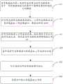
本发明实施例提供一种柔性显示面板的制备方法,如图1所示,该制备方法包括:An embodiment of the present invention provides a method for manufacturing a flexible display panel. As shown in FIG. 1 , the method includes:
S10、如图2所示,在承载基板10的第一表面形成呈固态的形态转变层20,其中,形态转变层20在光照条件下能够在固态和液态之间转换。S10. As shown in FIG. 2, a solid
其中,不对承载基板10的材料做限定,承载基板10可以是刚性材料,具体的,其材料可以包括但不限于:硅片、玻璃、云母片或其他刚性载体材料。The material of the
此处,形态转变层20具有的特性是在特定光照条件下呈固态,在特定光照条件下呈液态。这样一来,在制备显示器件40的部件时,使形态转变层20呈固态,以承载制备的部件;在将柔性衬底30与承载基板10剥离时,使形态转变层20呈液态,以便于柔性衬底30的剥离。Here, the
需要说明的是,此处形成的呈固态的形态转变层20可以是从无到有的形成,也可以是形态转变层20形态转变后形成。具体的,可以是在一个干净的承载基板10上形成一层呈固态的形态转变层20,也可以是将承载基板10上已有的呈液态的形态转变层20转变为固态。It should be noted that the solid
示例性的,将柔性衬底30从承载基板10上剥离后,此时形态转变层20呈液态,对形态转变层20进行固化,以形成呈固态的形态转变层20。Exemplarily, after the
为了降低对制备工艺的要求,在一些实施例中,形态转变层20的特性是在紫外光的照射下呈液态,在可见光的照射下呈固态。In order to reduce the requirement on the preparation process, in some embodiments, the characteristic of the
在一些实施例中,形态转变层20的材料具有热力学稳定的顺式和亚稳定的反式。In some embodiments, the material of the
在紫外光的照射下,稳定的顺式固态形态转变为亚稳定的反式液态形态。Under UV light irradiation, the stable cis-solid state transforms into a metastable trans-liquid state.
在一些实施例中,形态转变层20的材料包括基团。In some embodiments, the material of the
示例性的,形态转变层20的材料包括偶氮苯基团。Exemplarily, the material of the
分子结构示意图为:The schematic diagram of the molecular structure is:

这样一来,步骤S10在一些实施例中可以为:In this way, step S10 may be:
通过涂布或溅射(sputter)的方法在承载基板10上形成形态转变层20。The
采用可见光照射形态转变层20,以对形态转变层20进行固化。The shape-changing
S20、如图3所示,在形成有形态转变层20的承载基板10上形成柔性衬底30。S20. As shown in FIG. 3, a
不对柔性衬底30的材料做限定,其材料可以是聚合物、金属薄片或超薄玻璃,其中聚合物可以包括但不限于:聚酰亚胺(PI)、聚苯乙烯(PS)、聚碳酸酯(PC)、聚丙烯酸酯(PA)、聚醚酰亚胺(PEI)、聚醚砜(PES)、聚对苯二甲酸乙二醇酯(PETS)和聚对萘二甲酸乙二醇酯(PEN)等。The material of the
当然,本领域技术人员应该明白,如图4所示,FOLED必然包括形成在柔性衬底30上的显示器件40,显示器件40至少包括薄膜晶体管驱动元件、基本驱动电路、发光单元(阳极、阴极和有机材料功能层)、封装层,还可以包括彩膜、黑矩阵等。Of course, those skilled in the art should understand that, as shown in FIG. 4 , the FOLED necessarily includes a
S30、对呈固态的形态转变层20进行液化。S30 , liquefying the solid
也就是说,柔性显示面板的各部件制备完成后,需将柔性显示面板从承载基板10上剥离,此时,通过光照将呈固态的形态转变层20转换成液态。That is, after the components of the flexible display panel are prepared, the flexible display panel needs to be peeled off from the
在一些实施例中,步骤S30为:In some embodiments, step S30 is:
如图4所示,从承载基板10的与第一表面相对的第二表面所在侧对形成有柔性衬底30的承载基板10进行紫外光照射。As shown in FIG. 4 , the
S40、将柔性衬底30从承载基板10上剥离,以得到柔性显示面板。S40, peeling off the
在实际生产过程中,为了重复利用形态转变层20,在剥离柔性衬底30后,对呈液态的形态转变层20进行固化,以备下次使用。因此,对于上述制备方法,步骤S10可以是在制备过程的最开始,也可以是在步骤S40之后。In the actual production process, in order to reuse the
其中,为了提升剥离效果,可以在选取材料时,使形态转变层20对承载基板10的粘附力大于对另一侧的膜层(例如柔性衬底30)的粘附力。Wherein, in order to improve the peeling effect, when selecting materials, the adhesion force of the
本发明实施例提供的柔性显示面板的制备方法,由于形态转变层20在光照条件下即可完成固态和液态的转换,而光照对柔性衬底30上的显示器件40的影响可以忽略。因此,在进行柔性衬底30和承载基板10的剥离时,可以在形态转变层20变为液态的时候很轻松的使柔性衬底30和承载基板10剥离而不破坏显示元件。本发明实施例提供的柔性显示面板的制备方法,在制备过程中不会影响显示器件40,并且制作工艺和分离工艺简单,成本较低。In the method for fabricating a flexible display panel provided by the embodiment of the present invention, since the
在一些实施例中,如图5所示,形成柔性衬底30之前,该制备方法还包括:In some embodiments, as shown in FIG. 5, before forming the
S15、如图6所示,在形成有形态转变层20的承载基板10上形成遮光层50,遮光层50用于阻止光线穿过遮光层50。S15 , as shown in FIG. 6 , a
其中,遮光层50可以是形成在形态转变层20的表面,也可以是遮光层50和形态转变层20之间还形成有其他膜层。此处,不对遮光层50的材料进行限定,能够阻止光线穿过遮光层50即可,阻止光线穿过的方式可以是吸收光线或者改变光线的路径(反射光线)等。遮光层50的材料例如可以是高遮光性树脂类物质,或厚度达到一定要求的金属氧化物。The
这样一来,通过设置遮光层50,当遮光层50阻止从柔性衬底30所在侧射向遮光层50的光线时,遮光层50的存在可以避免在制备显示器件40(例如显示器件40中的薄膜晶体管驱动元件)时,光线对形态转变层20的影响。当遮光层50阻止从承载基板10所在侧射向遮光层50的光线时,遮光层50的存在可以避免在将形态转变层20液化时,光照对显示器件40的影响。In this way, by providing the light-
在一些实施例中,如图7所示,在形成遮光层50之前,该制备方法还包括:In some embodiments, as shown in FIG. 7, before forming the
S13、如图8所示,对呈固态的形态转变层20图案化,以使形态转变层20远离承载基板10一侧呈锯齿状,锯齿的顶角为90°。S13 , as shown in FIG. 8 , pattern the solid
在形态转变层20上形成的遮光层50与形态转变层20的锯齿相互契合。The
为了达到阻止光线穿过遮光层50的目的,令
其中,要满足上述条件,必然存在形态转变层20的折射率n1>遮光层50的折射率n2的关系,紫外光在形态转变层20与遮光层50的界面交界处发生全反射。Among them, to satisfy the above conditions, there must be a relationship between the refractive index n1 of the
对呈固态的形态转变层20进行液化时,紫外光垂直承载基板10入射。When the solid
这样一来,如图8所示,每个锯齿的顶角为90°,紫外光(箭头方向表示光路)垂直射向承载基板10,射向形态转变层20的锯齿的一侧边的紫外光的入射角即为45°,在形态转变层20与遮光层50的界面交界处发生全反射,反射角为45°,此时,紫外光以平行于承载基板10的方向射向锯齿的相对的另一侧边。紫外光的入射角为45°,在形态转变层20与遮光层50的界面交界处发生全反射,反射角为45°,此时,紫外光以垂直于承载基板10的方向射出(与紫外光射入时的光路平行,方向相反)。In this way, as shown in FIG. 8 , the apex angle of each sawtooth is 90°, and the ultraviolet light (the direction of the arrow indicates the light path) is directed to the
对呈固态的形态转变层20图案化时,例如可以通过事先准备好的纳米压印模版在呈固态的形态转变层20上压印出顶角为90°的锯齿。形成形状匹配的遮光层50时,不对遮光层50的材料进行限定,满足上述条件即可。遮光层50的材料可以是透明的,也可以是非透明材料。When patterning the solid
此处,一束平行的一定波长的紫外光射向形态转变层20后,会在第一个界面发生全反射后至第二个界面,再在第二个界面再次发生全反射,这样可以二次利用紫外光对形态转变层20进行转变,一方面。紫外光不会透过遮光层50,可以避免紫外光对显示器件40的影响;另一方面,可以减少初始紫外光的光束数量或者缩短紫外光照射时长,增加紫外光的利用。Here, after a beam of parallel ultraviolet light with a certain wavelength is directed to the
在一些实施例中,遮光层50的材料为透明材料。In some embodiments, the material of the
这样一来,柔性衬底30从承载基板10上脱离后,从显示器件40所在侧射向遮光层50的光线在遮光层50上可发生散射,减少了光线的全反射,当柔性显示面板为底发射型柔性显示面板时,可增加发光器件的出光效率。In this way, after the
当然,当遮光层50的材料为透明材料时,为了避免制备显示器件40时,紫外光对形态转变层20产生影响,可以将射向紫外光转变层的紫外光的波长与制备显示器件40时采用的紫外光的波长设置为不同,从而避免制备显示器件40时,紫外光对形态转变层20产生影响。Of course, when the material of the light-
本发明实施例还提供一种柔性显示面板,如图9所示,通过上述制备方法制备得到,有益效果与上述柔性显示面板的制备方法的有益效果相同,此处不再赘述。An embodiment of the present invention further provides a flexible display panel, as shown in FIG. 9 , which is prepared by the above-mentioned preparation method, and the beneficial effects are the same as those of the above-mentioned preparation method of the flexible display panel, which will not be repeated here.
本发明实施例还提供一种显示装置,包括上述柔性显示面板,有益效果与上述柔性显示面板的有益效果相同,此处不再赘述。An embodiment of the present invention further provides a display device including the above-mentioned flexible display panel, and the beneficial effects are the same as those of the above-mentioned flexible display panel, which will not be repeated here.
该显示装置可以为:电子纸、手机、平板电脑、电视机、显示器、笔记本电脑、数码相框、导航仪等任何具有显示功能的产品或部件。The display device can be any product or component with display function, such as electronic paper, mobile phone, tablet computer, TV, monitor, notebook computer, digital photo frame, and navigator.
以上所述,仅为本发明的具体实施方式,但本发明的保护范围并不局限于此,任何熟悉本技术领域的技术人员在本发明揭露的技术范围内,可轻易想到变化或替换,都应涵盖在本发明的保护范围之内。因此,本发明的保护范围应以所述权利要求的保护范围为准。The above are only specific embodiments of the present invention, but the protection scope of the present invention is not limited thereto. Any person skilled in the art can easily think of changes or substitutions within the technical scope disclosed by the present invention. should be included within the protection scope of the present invention. Therefore, the protection scope of the present invention should be based on the protection scope of the claims.
Claims (9)
Translated fromChinese
Priority Applications (1)
| Application Number | Priority Date | Filing Date | Title |
|---|---|---|---|
| CN201810575185.7ACN108766244B (en) | 2018-06-06 | 2018-06-06 | A flexible display panel, a preparation method thereof, and a display device |
Applications Claiming Priority (1)
| Application Number | Priority Date | Filing Date | Title |
|---|---|---|---|
| CN201810575185.7ACN108766244B (en) | 2018-06-06 | 2018-06-06 | A flexible display panel, a preparation method thereof, and a display device |
Publications (2)
| Publication Number | Publication Date |
|---|---|
| CN108766244A CN108766244A (en) | 2018-11-06 |
| CN108766244Btrue CN108766244B (en) | 2021-02-09 |
Family
ID=64000166
Family Applications (1)
| Application Number | Title | Priority Date | Filing Date |
|---|---|---|---|
| CN201810575185.7AActiveCN108766244B (en) | 2018-06-06 | 2018-06-06 | A flexible display panel, a preparation method thereof, and a display device |
Country Status (1)
| Country | Link |
|---|---|
| CN (1) | CN108766244B (en) |
Families Citing this family (4)
| Publication number | Priority date | Publication date | Assignee | Title |
|---|---|---|---|---|
| CN109841734B (en)* | 2019-03-28 | 2021-04-02 | 京东方科技集团股份有限公司 | Preparation method of flexible display panel, flexible display panel and display device |
| CN110634401A (en)* | 2019-08-23 | 2019-12-31 | 武汉华星光电半导体显示技术有限公司 | Cover plate and flexible display device |
| CN111276518A (en)* | 2020-02-10 | 2020-06-12 | 武汉华星光电半导体显示技术有限公司 | Flexible display panel, display device and display device manufacturing method |
| CN112002251B (en)* | 2020-08-06 | 2022-05-31 | Tcl华星光电技术有限公司 | Display panel and preparation method thereof |
Family Cites Families (11)
| Publication number | Priority date | Publication date | Assignee | Title |
|---|---|---|---|---|
| JP4991486B2 (en)* | 2007-10-31 | 2012-08-01 | ソニー株式会社 | Optical sheet, method for manufacturing the same, and display device |
| US7851318B2 (en)* | 2007-11-01 | 2010-12-14 | Semiconductor Energy Laboratory Co., Ltd. | Semiconductor substrate and method for manufacturing the same, and method for manufacturing semiconductor device |
| KR20140048441A (en)* | 2012-10-15 | 2014-04-24 | 삼성디스플레이 주식회사 | Organic light emitting display device with enhanced light efficiency and manufacturing method thereof |
| CN105280838B (en)* | 2015-09-22 | 2017-08-25 | 深圳市华星光电技术有限公司 | A kind of OLED luminescent devices and display device |
| WO2017057454A1 (en)* | 2015-09-30 | 2017-04-06 | 東レ株式会社 | Method for manufacturing light-emitting device, and method for manufacturing display device |
| CN106784311A (en)* | 2016-12-27 | 2017-05-31 | 武汉华星光电技术有限公司 | Flexible panel and preparation method thereof |
| CN106611823B (en)* | 2017-01-19 | 2018-07-10 | 江西冠能光电材料有限公司 | A kind of cross-linking organic semiconductor material of main part and its Organic Light Emitting Diode application |
| CN107221551B (en)* | 2017-05-16 | 2019-11-19 | 上海天马有机发光显示技术有限公司 | A kind of organic light emitting display panel, its production method and display device |
| CN106920902B (en)* | 2017-05-17 | 2018-11-23 | 京东方科技集团股份有限公司 | O L ED display substrate, manufacturing method thereof, display device and packaging method thereof |
| CN107275513B (en)* | 2017-05-31 | 2020-07-10 | 上海天马有机发光显示技术有限公司 | Manufacturing method of O L ED device cathode and display panel, display panel and display device |
| CN108075048B (en)* | 2017-12-12 | 2020-05-22 | 合肥鑫晟光电科技有限公司 | OLED panel, manufacturing method thereof and display device |
- 2018
- 2018-06-06CNCN201810575185.7Apatent/CN108766244B/enactiveActive
Also Published As
| Publication number | Publication date |
|---|---|
| CN108766244A (en) | 2018-11-06 |
Similar Documents
| Publication | Publication Date | Title |
|---|---|---|
| CN108766244B (en) | A flexible display panel, a preparation method thereof, and a display device | |
| CN107799574B (en) | Flexible display device and manufacturing method thereof | |
| KR102334815B1 (en) | Light-emitting device and peeling method | |
| US11309528B2 (en) | Flexible display panel and fabricating method thereof, flexible display apparatus | |
| CN106129088B (en) | A kind of display panel and preparation method, display device | |
| CN107968109A (en) | Flexible OLED display panel and preparation method thereof, display device | |
| US9594193B2 (en) | Printing plate, scattering layer, method for fabricating the same, and display apparatus | |
| US10153461B1 (en) | Display panel and method for manufacturing the same | |
| CN103988097B (en) | Duplexer and the manufacture method of duplexer | |
| CN107978687B (en) | Preparation method of flexible OLED display panel | |
| TW201512937A (en) | Touch panel | |
| CN107994129A (en) | The preparation method of flexible OLED display panel | |
| US10038159B2 (en) | Organic electroluminescent device structure and manufacturing for the same | |
| CN109273501B (en) | Flexible substrate, method for manufacturing the same, and display device | |
| CN107731887A (en) | The preparation method of flexible OLED display panel | |
| US11360618B2 (en) | Method for manufacturing touch screen, display device | |
| CN105117082A (en) | Manufacture method of touch screen and touch screen | |
| CN107093680A (en) | Metal auxiliary electrode and the manufacture method using its display device | |
| TW201716961A (en) | Film touch sensor | |
| CN105843431A (en) | Curved surface decorative plate and manufacturing method of curved surface display device | |
| CN107039594A (en) | Method for packing, flexible display panels and the display device of flexible display panels | |
| JP6677379B2 (en) | Circuit board manufacturing method | |
| CN102280164B (en) | Integrated flexible touch screen double-faced indium tin oxide (ITO) membrane structure | |
| TW201608428A (en) | Touch panel | |
| TW201545016A (en) | Touch display device and method of manufacturing same |
Legal Events
| Date | Code | Title | Description |
|---|---|---|---|
| PB01 | Publication | ||
| PB01 | Publication | ||
| SE01 | Entry into force of request for substantive examination | ||
| SE01 | Entry into force of request for substantive examination | ||
| GR01 | Patent grant | ||
| GR01 | Patent grant |