CN108731819B - Thermal image detection device - Google Patents
Thermal image detection deviceDownload PDFInfo
- Publication number
- CN108731819B CN108731819BCN201710416902.7ACN201710416902ACN108731819BCN 108731819 BCN108731819 BCN 108731819BCN 201710416902 ACN201710416902 ACN 201710416902ACN 108731819 BCN108731819 BCN 108731819B
- Authority
- CN
- China
- Prior art keywords
- camera
- measured
- measurement mode
- processor
- distance
- Prior art date
- Legal status (The legal status is an assumption and is not a legal conclusion. Google has not performed a legal analysis and makes no representation as to the accuracy of the status listed.)
- Expired - Fee Related
Links
Images


Classifications
- G—PHYSICS
- G03—PHOTOGRAPHY; CINEMATOGRAPHY; ANALOGOUS TECHNIQUES USING WAVES OTHER THAN OPTICAL WAVES; ELECTROGRAPHY; HOLOGRAPHY
- G03B—APPARATUS OR ARRANGEMENTS FOR TAKING PHOTOGRAPHS OR FOR PROJECTING OR VIEWING THEM; APPARATUS OR ARRANGEMENTS EMPLOYING ANALOGOUS TECHNIQUES USING WAVES OTHER THAN OPTICAL WAVES; ACCESSORIES THEREFOR
- G03B13/00—Viewfinders; Focusing aids for cameras; Means for focusing for cameras; Autofocus systems for cameras
- G03B13/18—Focusing aids
- G03B13/20—Rangefinders coupled with focusing arrangements, e.g. adjustment of rangefinder automatically focusing camera
- G—PHYSICS
- G01—MEASURING; TESTING
- G01J—MEASUREMENT OF INTENSITY, VELOCITY, SPECTRAL CONTENT, POLARISATION, PHASE OR PULSE CHARACTERISTICS OF INFRARED, VISIBLE OR ULTRAVIOLET LIGHT; COLORIMETRY; RADIATION PYROMETRY
- G01J5/00—Radiation pyrometry, e.g. infrared or optical thermometry
- G01J5/02—Constructional details
- G01J5/08—Optical arrangements
- H—ELECTRICITY
- H04—ELECTRIC COMMUNICATION TECHNIQUE
- H04N—PICTORIAL COMMUNICATION, e.g. TELEVISION
- H04N23/00—Cameras or camera modules comprising electronic image sensors; Control thereof
- H04N23/80—Camera processing pipelines; Components thereof
- H04N23/815—Camera processing pipelines; Components thereof for controlling the resolution by using a single image
- G—PHYSICS
- G01—MEASURING; TESTING
- G01J—MEASUREMENT OF INTENSITY, VELOCITY, SPECTRAL CONTENT, POLARISATION, PHASE OR PULSE CHARACTERISTICS OF INFRARED, VISIBLE OR ULTRAVIOLET LIGHT; COLORIMETRY; RADIATION PYROMETRY
- G01J5/00—Radiation pyrometry, e.g. infrared or optical thermometry
- G—PHYSICS
- G01—MEASURING; TESTING
- G01J—MEASUREMENT OF INTENSITY, VELOCITY, SPECTRAL CONTENT, POLARISATION, PHASE OR PULSE CHARACTERISTICS OF INFRARED, VISIBLE OR ULTRAVIOLET LIGHT; COLORIMETRY; RADIATION PYROMETRY
- G01J5/00—Radiation pyrometry, e.g. infrared or optical thermometry
- G01J5/0003—Radiation pyrometry, e.g. infrared or optical thermometry for sensing the radiant heat transfer of samples, e.g. emittance meter
- G—PHYSICS
- G01—MEASURING; TESTING
- G01J—MEASUREMENT OF INTENSITY, VELOCITY, SPECTRAL CONTENT, POLARISATION, PHASE OR PULSE CHARACTERISTICS OF INFRARED, VISIBLE OR ULTRAVIOLET LIGHT; COLORIMETRY; RADIATION PYROMETRY
- G01J5/00—Radiation pyrometry, e.g. infrared or optical thermometry
- G01J5/02—Constructional details
- G01J5/026—Control of working procedures of a pyrometer, other than calibration; Bandwidth calculation; Gain control
- G—PHYSICS
- G01—MEASURING; TESTING
- G01J—MEASUREMENT OF INTENSITY, VELOCITY, SPECTRAL CONTENT, POLARISATION, PHASE OR PULSE CHARACTERISTICS OF INFRARED, VISIBLE OR ULTRAVIOLET LIGHT; COLORIMETRY; RADIATION PYROMETRY
- G01J5/00—Radiation pyrometry, e.g. infrared or optical thermometry
- G01J5/02—Constructional details
- G01J5/0275—Control or determination of height or distance or angle information for sensors or receivers
- G—PHYSICS
- G01—MEASURING; TESTING
- G01J—MEASUREMENT OF INTENSITY, VELOCITY, SPECTRAL CONTENT, POLARISATION, PHASE OR PULSE CHARACTERISTICS OF INFRARED, VISIBLE OR ULTRAVIOLET LIGHT; COLORIMETRY; RADIATION PYROMETRY
- G01J5/00—Radiation pyrometry, e.g. infrared or optical thermometry
- G01J5/02—Constructional details
- G01J5/08—Optical arrangements
- G01J5/0846—Optical arrangements having multiple detectors for performing different types of detection, e.g. using radiometry and reflectometry channels
- G—PHYSICS
- G01—MEASURING; TESTING
- G01J—MEASUREMENT OF INTENSITY, VELOCITY, SPECTRAL CONTENT, POLARISATION, PHASE OR PULSE CHARACTERISTICS OF INFRARED, VISIBLE OR ULTRAVIOLET LIGHT; COLORIMETRY; RADIATION PYROMETRY
- G01J5/00—Radiation pyrometry, e.g. infrared or optical thermometry
- G01J5/02—Constructional details
- G01J5/08—Optical arrangements
- G01J5/0893—Arrangements to attach devices to a pyrometer, i.e. attaching an optical interface; Spatial relative arrangement of optical elements, e.g. folded beam path
- G—PHYSICS
- G01—MEASURING; TESTING
- G01K—MEASURING TEMPERATURE; MEASURING QUANTITY OF HEAT; THERMALLY-SENSITIVE ELEMENTS NOT OTHERWISE PROVIDED FOR
- G01K7/00—Measuring temperature based on the use of electric or magnetic elements directly sensitive to heat ; Power supply therefor, e.g. using thermoelectric elements
- G01K7/16—Measuring temperature based on the use of electric or magnetic elements directly sensitive to heat ; Power supply therefor, e.g. using thermoelectric elements using resistive elements
- G—PHYSICS
- G03—PHOTOGRAPHY; CINEMATOGRAPHY; ANALOGOUS TECHNIQUES USING WAVES OTHER THAN OPTICAL WAVES; ELECTROGRAPHY; HOLOGRAPHY
- G03B—APPARATUS OR ARRANGEMENTS FOR TAKING PHOTOGRAPHS OR FOR PROJECTING OR VIEWING THEM; APPARATUS OR ARRANGEMENTS EMPLOYING ANALOGOUS TECHNIQUES USING WAVES OTHER THAN OPTICAL WAVES; ACCESSORIES THEREFOR
- G03B17/00—Details of cameras or camera bodies; Accessories therefor
- G03B17/02—Bodies
- G03B17/06—Bodies with exposure meters or other indicators built into body but not connected to other camera members
- G—PHYSICS
- G03—PHOTOGRAPHY; CINEMATOGRAPHY; ANALOGOUS TECHNIQUES USING WAVES OTHER THAN OPTICAL WAVES; ELECTROGRAPHY; HOLOGRAPHY
- G03B—APPARATUS OR ARRANGEMENTS FOR TAKING PHOTOGRAPHS OR FOR PROJECTING OR VIEWING THEM; APPARATUS OR ARRANGEMENTS EMPLOYING ANALOGOUS TECHNIQUES USING WAVES OTHER THAN OPTICAL WAVES; ACCESSORIES THEREFOR
- G03B17/00—Details of cameras or camera bodies; Accessories therefor
- G03B17/02—Bodies
- G03B17/12—Bodies with means for supporting objectives, supplementary lenses, filters, masks, or turrets
- G—PHYSICS
- G03—PHOTOGRAPHY; CINEMATOGRAPHY; ANALOGOUS TECHNIQUES USING WAVES OTHER THAN OPTICAL WAVES; ELECTROGRAPHY; HOLOGRAPHY
- G03B—APPARATUS OR ARRANGEMENTS FOR TAKING PHOTOGRAPHS OR FOR PROJECTING OR VIEWING THEM; APPARATUS OR ARRANGEMENTS EMPLOYING ANALOGOUS TECHNIQUES USING WAVES OTHER THAN OPTICAL WAVES; ACCESSORIES THEREFOR
- G03B17/00—Details of cameras or camera bodies; Accessories therefor
- G03B17/18—Signals indicating condition of a camera member or suitability of light
- G—PHYSICS
- G03—PHOTOGRAPHY; CINEMATOGRAPHY; ANALOGOUS TECHNIQUES USING WAVES OTHER THAN OPTICAL WAVES; ELECTROGRAPHY; HOLOGRAPHY
- G03B—APPARATUS OR ARRANGEMENTS FOR TAKING PHOTOGRAPHS OR FOR PROJECTING OR VIEWING THEM; APPARATUS OR ARRANGEMENTS EMPLOYING ANALOGOUS TECHNIQUES USING WAVES OTHER THAN OPTICAL WAVES; ACCESSORIES THEREFOR
- G03B35/00—Stereoscopic photography
- G03B35/08—Stereoscopic photography by simultaneous recording
- H—ELECTRICITY
- H04—ELECTRIC COMMUNICATION TECHNIQUE
- H04N—PICTORIAL COMMUNICATION, e.g. TELEVISION
- H04N17/00—Diagnosis, testing or measuring for television systems or their details
- H04N17/002—Diagnosis, testing or measuring for television systems or their details for television cameras
- H—ELECTRICITY
- H04—ELECTRIC COMMUNICATION TECHNIQUE
- H04N—PICTORIAL COMMUNICATION, e.g. TELEVISION
- H04N23/00—Cameras or camera modules comprising electronic image sensors; Control thereof
- H04N23/20—Cameras or camera modules comprising electronic image sensors; Control thereof for generating image signals from infrared radiation only
- H04N23/23—Cameras or camera modules comprising electronic image sensors; Control thereof for generating image signals from infrared radiation only from thermal infrared radiation
- H—ELECTRICITY
- H04—ELECTRIC COMMUNICATION TECHNIQUE
- H04N—PICTORIAL COMMUNICATION, e.g. TELEVISION
- H04N23/00—Cameras or camera modules comprising electronic image sensors; Control thereof
- H04N23/45—Cameras or camera modules comprising electronic image sensors; Control thereof for generating image signals from two or more image sensors being of different type or operating in different modes, e.g. with a CMOS sensor for moving images in combination with a charge-coupled device [CCD] for still images
- H—ELECTRICITY
- H04—ELECTRIC COMMUNICATION TECHNIQUE
- H04N—PICTORIAL COMMUNICATION, e.g. TELEVISION
- H04N23/00—Cameras or camera modules comprising electronic image sensors; Control thereof
- H04N23/60—Control of cameras or camera modules
- H04N23/65—Control of camera operation in relation to power supply
- G—PHYSICS
- G01—MEASURING; TESTING
- G01J—MEASUREMENT OF INTENSITY, VELOCITY, SPECTRAL CONTENT, POLARISATION, PHASE OR PULSE CHARACTERISTICS OF INFRARED, VISIBLE OR ULTRAVIOLET LIGHT; COLORIMETRY; RADIATION PYROMETRY
- G01J5/00—Radiation pyrometry, e.g. infrared or optical thermometry
- G01J2005/0077—Imaging
Landscapes
- Physics & Mathematics (AREA)
- General Physics & Mathematics (AREA)
- Spectroscopy & Molecular Physics (AREA)
- Engineering & Computer Science (AREA)
- Multimedia (AREA)
- Signal Processing (AREA)
- Health & Medical Sciences (AREA)
- Toxicology (AREA)
- Human Computer Interaction (AREA)
- Biomedical Technology (AREA)
- General Health & Medical Sciences (AREA)
- Length Measuring Devices By Optical Means (AREA)
- Radiation Pyrometers (AREA)
Abstract
Description
Translated fromChinese技术领域technical field
本发明是关于一种热像检测装置;具体而言,本发明是关于一种可自动调整测量温度以达精准检测个别的目标物表面温度的热像检测装置。The present invention relates to a thermal image detection device; in particular, the present invention relates to a thermal image detection device that can automatically adjust the measurement temperature to accurately detect the surface temperature of an individual target.
背景技术Background technique
一般而言,热像检测是根据待测物表面的辐射能计算待测物表面温度的技术。现有的热像检测装置所呈现的温度数据有不准确的问题。例如,通过使用者自行评估距离后手动输入距离数值。然而,使用者自行评估的距离数值与实际的距离数值之间可能有很大的偏差,造成不准确。这也代表现有的热像检测装置无法主动地调整温度数据且无法同时检测不同位置或移动中目标物的温度数据。此外,依靠手动输入的方式在使用上也不方便。因此,现有热像检测装置仍有待改进。Generally speaking, thermal image detection is a technology that calculates the surface temperature of the object to be measured according to the radiant energy of the surface of the object to be measured. The temperature data presented by the existing thermal image detection device has the problem of inaccuracy. For example, manually enter the distance value after evaluating the distance by the user. However, there may be a large deviation between the distance value estimated by the user and the actual distance value, resulting in inaccuracy. This also means that the existing thermal image detection device cannot actively adjust the temperature data and cannot detect the temperature data of objects in different positions or moving at the same time. In addition, relying on manual input is inconvenient to use. Therefore, the existing thermal image detection devices still need to be improved.
发明内容SUMMARY OF THE INVENTION
本发明的一目的在于提供一种热像检测装置,可同时检测不同位置目标物并提高对待测物测量温度的准确度。One object of the present invention is to provide a thermal image detection device that can simultaneously detect objects at different positions and improve the accuracy of temperature measurement of the object to be measured.
热像检测装置包含第一摄影机、第二摄影机、热像摄影机、以及处理器。第一摄影机和第二摄影机安装于设置面。热像摄影机设置于第一摄影机和第二摄影机之间,并侦测待测物以产生第一温度值。处理器耦接第一摄影机、第二摄影机、以及热像摄影机。处理器包含控制单元。控制单元依照第一测量模式及第二测量模式的设定而控制第一摄影机及第二摄影机。在第一测量模式下,控制单元撷取第一摄影机及第二摄影机画面,以量测待测物至设置面的第一距离。在第二测量模式下,控制单元撷取第一摄影机画面,以量测待测物的尺寸。处理器根据第一温度值、第一距离与待测物的尺寸决定待测物的第二温度值。The thermal image detection device includes a first camera, a second camera, a thermal image camera, and a processor. The first camera and the second camera are mounted on the installation surface. The thermal imaging camera is arranged between the first camera and the second camera, and detects the object to be tested to generate a first temperature value. The processor is coupled to the first camera, the second camera, and the thermal imaging camera. The processor contains the control unit. The control unit controls the first camera and the second camera according to the settings of the first measurement mode and the second measurement mode. In the first measurement mode, the control unit captures the images of the first camera and the second camera to measure the first distance from the object to be measured to the setting surface. In the second measurement mode, the control unit captures the frame of the first camera to measure the size of the object to be measured. The processor determines the second temperature value of the object to be tested according to the first temperature value, the first distance and the size of the object to be tested.
于一实施例中,第一摄影机与第二摄影机是沿一方向水平设置。In one embodiment, the first camera and the second camera are arranged horizontally along a direction.
于一实施例中,第一摄影机、第二摄影机、以及热像摄影机具有相同设置高度。In one embodiment, the first camera, the second camera, and the thermal imaging camera have the same height.
于一实施例中,更包含一储存单元,储存第一对应表与第二对应表,第一对应表内包括第一距离与待测物的尺寸的比值和热量散失率的对应关系,处理器依据第一对应表决定热量散失率;第二对应表内包括第一温度、热量散失率与补偿温差值的对应关系,处理器依据第二对应表决定补偿温差值以获得第二温度值。In one embodiment, a storage unit is further included to store the first correspondence table and the second correspondence table, wherein the first correspondence table includes the ratio of the first distance to the size of the object to be measured and the corresponding relationship of the heat dissipation rate, the processor The heat loss rate is determined according to the first correspondence table; the second correspondence table includes the correspondence between the first temperature, the heat loss rate and the compensation temperature difference value, and the processor determines the compensation temperature difference value according to the second correspondence table to obtain the second temperature value.
于一实施例中,处理器更包含影像辨识单元,影像辨识单元是判断拍摄画面中是否出现待测物,并决定待测物对应的第一像素值。In one embodiment, the processor further includes an image recognition unit, and the image recognition unit determines whether the object to be measured appears in the photographed image, and determines the first pixel value corresponding to the object to be measured.
于一实施例中,在第一测量模式,处理器根据第一摄影机与第二摄影机之间的间距、焦距,以及第一摄影机与第二摄影机相对待测物的视差,求得第一距离。In one embodiment, in the first measurement mode, the processor obtains the first distance according to the distance between the first camera and the second camera, the focal length, and the parallax of the first camera and the second camera relative to the object to be measured.
于一实施例中,在第二测量模式,处理器根据第一摄影机的视角、解析度、第一距离、以及待测物对应的第一像素值,求得待测物的尺寸。In one embodiment, in the second measurement mode, the processor obtains the size of the object to be measured according to the viewing angle, resolution, first distance of the first camera, and the first pixel value corresponding to the object to be measured.
于一实施例中,处理器设定有第三测量模式,当处理器侦测第二摄影机坏损时,控制单元依照第三测量模式的设定而控制第一摄影机;其中在第三测量模式,处理器根据待测物对应的第一像素值,求得待测物的尺寸;处理器根据第一摄影机的视角、解析度、待测物的尺寸,求得第一距离。In one embodiment, the processor is set with a third measurement mode, and when the processor detects that the second camera is damaged, the control unit controls the first camera according to the setting of the third measurement mode; wherein in the third measurement mode , the processor obtains the size of the object to be measured according to the first pixel value corresponding to the object to be measured; the processor obtains the first distance according to the viewing angle, resolution, and size of the object to be measured of the first camera.
于一实施例中,在进入第三测量模式之前,执行预测量模式,于预测量模式,处理器根据第一摄影机的视角、解析度、待测物至设置面的预设距离、以及待测物对应的初始像素值,求得待测物的初始尺寸;于第三测量模式,处理器根据初始尺寸、初始像素值、以及第一像素值,求得待测物的尺寸。In one embodiment, before entering the third measurement mode, a pre-measurement mode is executed. In the pre-measurement mode, the processor is based on the viewing angle and resolution of the first camera, the preset distance from the object to be measured to the setting surface, and the measurement The initial pixel value corresponding to the object is used to obtain the initial size of the object to be measured; in the third measurement mode, the processor obtains the size of the object to be measured according to the initial size, the initial pixel value, and the first pixel value.
附图说明Description of drawings
图1为本发明热像检测装置的一实施例示意图;FIG. 1 is a schematic diagram of an embodiment of a thermal image detection device according to the present invention;
图2为本发明热像检测装置的一实施例方块图;FIG. 2 is a block diagram of an embodiment of the thermal image detection device of the present invention;
图3为调整温度的一实施例流程图;3 is a flow chart of an embodiment of adjusting temperature;
图4为第一测量模式的一实施例流程图;4 is a flowchart of an embodiment of the first measurement mode;
图5为本发明热像检测装置的另一实施例方块图;5 is a block diagram of another embodiment of the thermal image detection device of the present invention;
图6为调整温度的另一实施例流程图;6 is a flowchart of another embodiment of adjusting temperature;
图7为第二测量模式的一实施例流程图;FIG. 7 is a flowchart of an embodiment of the second measurement mode;
图8为本发明热像检测装置的另一实施例示意图;8 is a schematic diagram of another embodiment of the thermal image detection device of the present invention;
图9为调整温度的另一实施例流程图;9 is a flowchart of another embodiment of adjusting temperature;
图10为预测量模式的一实施例流程图;FIG. 10 is a flow chart of an embodiment of a pre-measurement mode;
图11为第三测量模式的一实施例流程图。FIG. 11 is a flowchart of an embodiment of the third measurement mode.
主要元件符号说明:Description of main component symbols:
10 热像检测装置10 Thermal imaging detection device
12 设置面12 Set face
110 第一摄影机110 First camera
120 第二摄影机120 Second camera
130 热像摄影机130 Thermal Camera
140 处理器140 processors
141 控制单元141 Control unit
143 影像辨识单元143 Image recognition unit
150 储存单元150 storage units
161 第一对应表161 First correspondence table
162 第二对应表162 Second correspondence table
170 通信单元170 Communication unit
A 方向A direction
具体实施方式Detailed ways
本发明提供一种热像检测装置,通过自动量测待测物距离、大小以个别调整目标物测量温度。图1为本发明热像检测装置10的一实施例示意图。如图1所示,热像检测装置10包含第一摄影机110、第二摄影机120、热像摄影机130。第一摄影机110和第二摄影机120安装于设置面12。热像摄影机130设置于第一摄影机110和第二摄影机120之间,并侦测待测物以产生第一温度值。如图1的实施例所示,第一摄影机110与第二摄影机120沿一方向A水平设置。于一实施例,第一摄影机110、第二摄影机120、以及热像摄影机130具有相同设置高度。由此第一摄影机110、第二摄影机120、热像摄影机130的视野范围可以重叠,提高检测范围。The invention provides a thermal image detection device, which can individually adjust the measured temperature of the target object by automatically measuring the distance and size of the object to be measured. FIG. 1 is a schematic diagram of an embodiment of a thermal
请同时参考图2。图2为本发明热像检测装置10的一实施例方块图。如图2所示,热像检测装置10还包含处理器140。处理器140耦接第一摄影机110、第二摄影机120、以及热像摄影机130。处理器140包含控制单元141。控制单元141依照第一测量模式及第二测量模式的设定而控制第一摄影机110及第二摄影机120。于一实施例,热像检测装置10可包含通信单元170,将拍摄影像及运算结果传输(有线或无线方式)到主控台。Please also refer to Figure 2. FIG. 2 is a block diagram of an embodiment of the thermal
图3为调整温度的一实施例流程图。如图3所示,在步骤S10:热像摄影机产生第一温度值。例如,热像摄影机将侦测的热辐射值转为第一温度值。在步骤S30:于第一测量模式量测第一距离。在步骤S50:于第二测量模式量测待测物的尺寸。FIG. 3 is a flow chart of an embodiment of adjusting the temperature. As shown in FIG. 3 , in step S10 : the thermal imaging camera generates a first temperature value. For example, the thermal imaging camera converts the detected thermal radiation value into a first temperature value. In step S30: measure the first distance in the first measurement mode. In step S50 : measure the size of the object to be measured in the second measurement mode.
例如,在第一测量模式下,控制单元启动第一摄影机及第二摄影机,撷取第一摄影机和第二摄影机的画面以量测画面中所有像素点至设置面的距离,并进行记录。在第二测量模式下,控制单元撷取第一摄影机画面,以量测待测物的尺寸。例如,比较前后画面的差异后,以确认待测物的尺寸(长/宽)。此时第二摄影机保持开启,使控制单元可持续接收第一摄影机和第二摄影机的画面,以持续量测画面中所有像素点至设置面的距离。此外,在确认待测物的位置时,可撷取前述记录的距离,获得待测物至设置面的第一距离。接着在步骤S70:调整待测物的温度为第二温度值。处理器根据第一温度值、第一距离与待测物的尺寸决定待测物的第二温度值。由此可提高对待测物测量温度的准确度。应理解,上述为说明方便,于第二测量模式启动第一摄影机,但不限于此。For example, in the first measurement mode, the control unit activates the first camera and the second camera, captures the pictures of the first camera and the second camera to measure the distance from all pixels in the picture to the setting surface, and records. In the second measurement mode, the control unit captures the frame of the first camera to measure the size of the object to be measured. For example, after comparing the difference between the before and after pictures, to confirm the size (length/width) of the object to be measured. At this time, the second camera is kept on, so that the control unit can continuously receive the images of the first camera and the second camera, so as to continuously measure the distance from all the pixels in the image to the setting surface. In addition, when the position of the object to be measured is confirmed, the recorded distance can be captured to obtain the first distance from the object to be measured to the setting surface. Next, in step S70 : adjusting the temperature of the object to be tested to a second temperature value. The processor determines the second temperature value of the object to be tested according to the first temperature value, the first distance and the size of the object to be tested. As a result, the accuracy of measuring the temperature of the object to be measured can be improved. It should be understood that, for the convenience of description, the first camera is activated in the second measurement mode, but it is not limited thereto.
图4为第一测量模式的一实施例流程图。如图4所示,在步骤S301:撷取间距、焦距、视差。具体而言,通过第一摄影机及第二摄影机,与欲求取的第一距离有如下关系:FIG. 4 is a flowchart of an embodiment of the first measurement mode. As shown in FIG. 4 , in step S301 : capture distance, focal length, and parallax. Specifically, through the first camera and the second camera, the first distance to be obtained has the following relationship:

其中,f为第一摄影机及第二摄影机的焦距、d为第一摄影机及第二摄影机相对待测物的视差、T为第一摄影机及第二摄影机的间距(即两摄影机沿设置方向的长度)、D为待测物至设置面的第一距离。自系统设定值撷取间距、焦距、视差,以求得第一距离。接着,在步骤S303:决定第一距离。Among them, f is the focal length of the first camera and the second camera, d is the parallax of the first camera and the second camera relative to the object to be measured, T is the distance between the first camera and the second camera (that is, the length of the two cameras along the installation direction) ) and D are the first distance from the object to be tested to the setting surface. The distance, focal length, and parallax are captured from the system setting values to obtain the first distance. Next, in step S303: determine the first distance.
图5为本发明热像检测装置10的另一实施例方块图。如图5所示,处理器140还包含影像辨识单元143与储存单元150。影像辨识单元143判断拍摄画面中是否出现待测物,并决定待测物对应的第一像素值。储存单元150储存对应表(例如第一对应表161和第二对应表162)。对应表内包含待测物距离、待测物尺寸及温度值等参数。处理器可依据所述对应表将第一温度值调整为第二温度值。于一实施例,热像检测装置10可包含通信单元170,可将拍摄影像及运算结果传输(有线或无线方式)到主控台。FIG. 5 is a block diagram of another embodiment of the thermal
图6为调整温度的另一实施例流程图。如图6所示,在步骤S10:热像摄影机产生第一温度值。在步骤S30:于第一测量模式量测第一距离。接着,在步骤S40判断是否有待测物。在步骤S50:于第二测量模式量测待测物的尺寸。FIG. 6 is a flow chart of another embodiment of adjusting the temperature. As shown in FIG. 6, in step S10: the thermal imaging camera generates a first temperature value. In step S30: measure the first distance in the first measurement mode. Next, in step S40, it is determined whether there is an object to be tested. In step S50 : measure the size of the object to be measured in the second measurement mode.
例如,在第一测量模式下,控制单元启动第一摄影机及第二摄影机,采用第一摄影机和第二摄影机的画面以量测画面中所有像素点至设置面的距离,并进行记录。当影像辨识单元判断待测物的位置,记录其位置。此外,在影像辨识单元确认待测物的位置时,可撷取前述记录的距离,获得待测物至设置面的第一距离。在第二测量模式下,控制单元采用第一摄影机画面,以量测待测物的尺寸。例如,通过第一摄影机与影像辨识单元决定待测物的尺寸。For example, in the first measurement mode, the control unit activates the first camera and the second camera, and uses the images of the first camera and the second camera to measure and record the distances from all pixels in the image to the setting surface. When the image recognition unit determines the position of the object to be tested, its position is recorded. In addition, when the image recognition unit confirms the position of the object to be measured, the recorded distance can be captured to obtain the first distance from the object to be measured to the setting surface. In the second measurement mode, the control unit uses the first camera image to measure the size of the object to be measured. For example, the size of the object to be measured is determined by the first camera and the image recognition unit.
接着在步骤S70:调整待测物的温度为第二温度值。处理器根据第一温度值、第一距离与待测物的尺寸决定待测物的第二温度值。由此可提高对待测物测量温度的准确度。应理解,上述为说明方便,于第二测量模式启动第一摄影机,但不限于此。Next, in step S70 : adjusting the temperature of the object to be tested to a second temperature value. The processor determines the second temperature value of the object to be tested according to the first temperature value, the first distance and the size of the object to be tested. As a result, the accuracy of measuring the temperature of the object to be measured can be improved. It should be understood that, for the convenience of description, the first camera is activated in the second measurement mode, but it is not limited thereto.
图7为第二测量模式的一实施例流程图。如图7所示,在步骤S501:撷取视角,并根据第一距离以决定横向尺寸。具体而言,通过第一摄影机,与欲求取的横向尺寸有如下关系:FIG. 7 is a flowchart of an embodiment of the second measurement mode. As shown in FIG. 7 , in step S501 : the viewing angle is captured, and the horizontal size is determined according to the first distance. Specifically, the first camera has the following relationship with the desired lateral size:

其中,θ为第一摄影机的水平视角的二分之一、D为待测物至设置面的第一距离、X为待测物所在位置的横向尺寸。Wherein, θ is half of the horizontal viewing angle of the first camera, D is the first distance from the object to be measured to the setting surface, and X is the lateral dimension of the position of the object to be measured.
接着,在步骤S503:撷取第一摄影机的解析度。在步骤S505:决定第一像素值。具体而言,通过第一摄影机,与欲求取的待测物宽度有如下关系:Next, in step S503 : capturing the resolution of the first camera. In step S505: determine the first pixel value. Specifically, through the first camera, the width of the object to be measured has the following relationship:

其中,X为待测物所在位置的横向尺寸、PC为第一摄影机的横向解析度、PW1为待测物对应的第一像素值、W1为待测物宽度。处理器撷取第一摄影机的横向解析度。影像辨识单元可识别待测物,以获得待测物对应的第一像素值。例如,辨识人脸所占范围,以得到人脸长、宽的像素值。接着,在步骤S507:决定待测物宽度。Wherein, X is the lateral dimension of the position of the object to be tested, PC is the lateral resolution of the first camera,PW1 is thefirst pixel value corresponding to the object to be tested, and W1 is the width of the object to be tested. The processor captures the lateral resolution of the first camera. The image recognition unit can identify the object to be tested to obtain the first pixel value corresponding to the object to be tested. For example, the range occupied by the face is identified to obtain the pixel values of the length and width of the face. Next, in step S507: determine the width of the object to be tested.
应理解,对于待测物长度而言,也可采用类似上述的方式获得待测物尺寸。例如,撷取第一摄影机的垂直视角,根据垂直视角及第一距离决定待测物所在位置的纵向尺寸。再根据纵向尺寸与待测物长度的比例关系求出待测物长度。It should be understood that for the length of the object to be measured, the size of the object to be measured can also be obtained in a manner similar to the above. For example, the vertical viewing angle of the first camera is captured, and the vertical size of the position of the object to be measured is determined according to the vertical viewing angle and the first distance. Then, according to the proportional relationship between the longitudinal dimension and the length of the object to be measured, the length of the object to be measured is obtained.
处理器根据上述关系式的计算结果并配合储存单元中的对应表决定待测物的第二温度值。举例而言,储存单元中具有第一对应表与第二对应表,表示如下:The processor determines the second temperature value of the object to be tested according to the calculation result of the above relational expression and in cooperation with the corresponding table in the storage unit. For example, the storage unit has a first correspondence table and a second correspondence table, which are represented as follows:

表一Table I
上列表一为第一对应表的例子,待测物长度(L1)与第一距离(D)的比值具有不同M值(M1、M2…)。待测物宽度(W1)与第一距离(D)的比值具有不同N值(N1、N2…)。每个M值在不同N值具有对应的热量散失率(Q1、Q2…)。如表一所示,第一对应表内包括第一距离与待测物的尺寸的比值和热量散失率的对应关系。处理器依据第一对应表决定热量散失率。The above table 1 is an example of the first correspondence table, and the ratio of the length of the object to be tested (L1 ) to the first distance (D) has different M values (M1, M2 . . . ). The ratio of the object width (W1 ) to the first distance (D) has different N values ( N1 , N2 . . . ). Each M value has a corresponding heat loss rate (Q1, Q2...) at a different N value. As shown in Table 1, the first correspondence table includes the correspondence between the ratio of the first distance to the size of the object to be measured and the heat dissipation rate. The processor determines the heat dissipation rate according to the first correspondence table.
在表二中:In Table 2:


表二Table II
上列表二为第二对应表的例子,第一温度值(T11、T12…)在不同热量散失率(Q1、Q2…)具有对应的补偿温差值(CV1、CV2…)。如表二所示,第二对应表内包括第一温度、热量散失率与补偿温差值的对应关系。处理器依据第二对应表决定补偿温差值以获得第二温度值。由此将第一温度值调整为第二温度值。Table 2 above is an example of the second correspondence table. The first temperature values (T11, T12...) have corresponding compensation temperature difference values (CV1, CV2...) at different heat dissipation rates (Q1, Q2...). As shown in Table 2, the second correspondence table includes the correspondence between the first temperature, the heat dissipation rate and the compensation temperature difference value. The processor determines the compensation temperature difference value to obtain the second temperature value according to the second correspondence table. As a result, the first temperature value is adjusted to the second temperature value.
图8为本发明热像检测装置的另一实施例示意图。如图8的实施例所示,第一摄影机与第二摄影机沿一方向水平设置。第一摄影机、第二摄影机、以及热像摄影机具有不同设置高度。换言之,热像摄影机可视拍摄需求及产品设计改变设置位置。FIG. 8 is a schematic diagram of another embodiment of the thermal image detection device of the present invention. As shown in the embodiment of FIG. 8 , the first camera and the second camera are arranged horizontally in one direction. The first camera, the second camera, and the thermal imaging camera have different setting heights. In other words, the thermal imaging camera can change the setting position according to the shooting requirements and product design.
图9为调整温度的另一实施例流程图。如图9所示,处理器设定有第三测量模式。在步骤S10:热像摄影机产生第一温度值。接着,在步骤S20判断第一摄影机和第二摄影机是否损坏。当结果显示第一摄影机和第二摄影机未损坏,则为步骤S21。接着,经步骤S30、步骤S50、步骤S70决定待测物的第二温度值的方式如上述说明,在此不另赘述。FIG. 9 is a flow chart of another embodiment of adjusting the temperature. As shown in FIG. 9, the processor is set with a third measurement mode. In step S10: the thermal imaging camera generates a first temperature value. Next, in step S20, it is determined whether the first camera and the second camera are damaged. When the result shows that the first camera and the second camera are not damaged, it goes to step S21. Next, the manner of determining the second temperature value of the object to be tested through steps S30 , S50 and S70 is as described above, and will not be repeated here.
当结果显示第二摄影机损坏,则为步骤S22。接着,在步骤S60:于第三测量模式量测第一距离和待测物的尺寸。例如,根据预设条件决定待测物初始尺寸作为参考值。在第三测量模式下,控制单元启动第一摄影机并采用第一摄影机画面。当影像辨识单元判断待测物的位置,记录其位置。通过第一摄影机与影像辨识单元并根据初始尺寸以决定待测物的距离以及待测物的尺寸。接着在步骤S70:调整待测物的温度为第二温度值。When the result shows that the second camera is damaged, it goes to step S22. Next, in step S60: measure the first distance and the size of the object to be measured in the third measurement mode. For example, the initial size of the object to be tested is determined as a reference value according to a preset condition. In the third measurement mode, the control unit activates the first camera and adopts the first camera picture. When the image recognition unit determines the position of the object to be tested, its position is recorded. The distance of the object to be measured and the size of the object to be measured are determined by the first camera and the image recognition unit and according to the initial size. Next, in step S70 : adjusting the temperature of the object to be tested to a second temperature value.
另外,当结果显示第一摄影机和第二摄影机皆损坏,则为步骤S23。处理器例如可经由通信单元发送警示信号(步骤S80),将故障事件通知主机端。In addition, when the result shows that both the first camera and the second camera are damaged, it goes to step S23. For example, the processor may send a warning signal via the communication unit (step S80 ) to notify the host of the failure event.
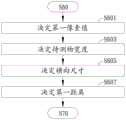
图10为预测量模式的一实施例流程图。在进入第三测量模式之前,执行预测量模式以获得预设条件下的数值作为参考值。如图10所示,在步骤S221:撷取视角,并根据预设距离以决定初始横向尺寸。具体而言,通过第一摄影机,与欲求取的初始横向尺寸有如下关系:FIG. 10 is a flowchart of an embodiment of the pre-measurement mode. Before entering the third measurement mode, the pre-measurement mode is executed to obtain the numerical value under the preset condition as the reference value. As shown in FIG. 10 , in step S221 : the viewing angle is captured, and the initial horizontal size is determined according to the preset distance. Specifically, through the first camera, there is the following relationship with the initial horizontal dimension to be obtained:

其中,θ为第一摄影机的水平视角的二分之一、D0为待测物至设置面的预设距离、X0为待测物所在位置的初始横向尺寸。例如,预先建立欲识别的待测物(像是人脸、车子…)以及多个预设距离,表示待测物位在某个预设距离下的情况。根据预设条件求取初始横向尺寸。Wherein, θ is half of the horizontal viewing angle of the first camera, D0 is the preset distance from the object to be measured to the setting surface, and X0 is the initial lateral dimension of the position of the object to be measured. For example, an object to be detected (such as a human face, a car, etc.) and a plurality of preset distances are pre-established to indicate the situation of the object to be detected at a certain preset distance. The initial horizontal dimension is obtained according to the preset conditions.
在步骤S223:撷取第一摄影机的解析度。在步骤S225:决定初始像素值。具体而言,通过第一摄影机,与欲求取的待测物初始宽度有如下关系:In step S223: the resolution of the first camera is captured. At step S225: determine the initial pixel value. Specifically, the first camera has the following relationship with the initial width of the object to be tested:

其中,X0为待测物所在位置的横向尺寸、PC为第一摄影机的横向解析度、PW0为待测物对应的初始像素值、W0为待测物初始宽度。处理器撷取第一摄影机的横向解析度。影像辨识单元可识别待测物,以获得待测物对应的初始像素值。接着,在步骤S227:决定待测物初始宽度。应理解,对于待测物初始长度而言,也可采用类似上述的方式获得待测物初始尺寸。Wherein, X0 is the lateral dimension of the position of the object to be tested, PC is the lateral resolution of the first camera,PW0 is the initial pixel value corresponding to the object to be tested, and W0 is the initial width of the object to be tested. The processor captures the lateral resolution of the first camera. The image recognition unit can identify the object to be tested to obtain the initial pixel value corresponding to the object to be tested. Next, in step S227: determine the initial width of the object to be tested. It should be understood that for the initial length of the object to be tested, the initial size of the object to be tested can also be obtained in a manner similar to the above.
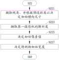
图11为第三测量模式的一实施例流程图。如图11所示,在步骤S601:决定第一像素值。在步骤S603:决定待测物宽度。具体而言,通过第一摄影机,与欲求取的待测物宽度有如下关系:FIG. 11 is a flowchart of an embodiment of the third measurement mode. As shown in FIG. 11 , in step S601 : determine the first pixel value. In step S603: the width of the object to be tested is determined. Specifically, through the first camera, the width of the object to be measured has the following relationship:

其中,W0为待测物初始宽度、PW0为待测物对应的初始像素值、PW1为待测物对应的第一像素值、W1为待测物宽度。例如待测物移动后,影像辨识单元可识别待测物,以获得待测物对应的第一像素值。处理器根据初始宽度、初始像素值、以及第一像素值,求得待测物的宽度。应理解,对于待测物长度而言,也可采用类似上述的方式获得待测物长度。Wherein, W0 is the initial width of the object to be tested, PW0 is the initial pixel value corresponding to the object to be tested, PW1 is the first pixel value corresponding to the object to be tested, and W1 is the width of the object to be tested. For example, after the object to be measured moves, the image recognition unit can identify the object to be measured to obtain the first pixel value corresponding to the object to be measured. The processor obtains the width of the object to be measured according to the initial width, the initial pixel value, and the first pixel value. It should be understood that for the length of the object to be tested, the length of the object to be tested can also be obtained in a manner similar to the above.
在步骤S605:决定横向尺寸。具体而言,通过第一摄影机,与欲求取的横向尺寸有如下关系:At step S605: determine the horizontal size. Specifically, the first camera has the following relationship with the desired lateral size:

其中,X1为待测物所在位置的横向尺寸、PC为第一摄影机的横向解析度、PW1为待测物对应的第一像素值、W1为待测物宽度。处理器根据上述计算结果以获得待测物所在位置的横向尺寸。Wherein, X1 is the lateral dimension of the position of the object to be measured, PC is the lateral resolution of the first camera,PW1 is the first pixel value corresponding to the object to be measured, and W1 is the width of the object to be measured. The processor obtains the lateral dimension of the position of the object to be measured according to the above calculation result.
在步骤S607:决定第一距离。具体而言,通过第一摄影机,与欲求取的第一距离有如下关系:At step S607: the first distance is determined. Specifically, through the first camera, the first distance to be obtained has the following relationship:

其中,D0为待测物至设置面的预设距离、X0为待测物所在位置的初始横向尺寸、D1为待测物至设置面的第一距离、X1为待测物所在位置的横向尺寸。处理器根据上述计算结果以获得第一距离。由此,在侦测第二摄影机损坏时,可利用如图10及图11例示的方式获取所需参数,以调整待测物的温度为第二温度值。由此可提高对待测物测量温度的准确度。Among them, D0 is the preset distance from the object to be measured to the setting surface, X0 is the initial lateral dimension of the location of the object to be measured, D1 is the first distance from the object to be measured to the setting surface, and X1 is the location of the object to be measured. The horizontal dimension of the location. The processor obtains the first distance according to the above calculation result. Therefore, when the damage of the second camera is detected, the required parameters can be obtained in the manner as illustrated in FIG. 10 and FIG. 11 to adjust the temperature of the object to be tested to the second temperature value. As a result, the accuracy of measuring the temperature of the object to be measured can be improved.
本发明已由上述相关实施例加以描述,然而上述实施例仅为实施本发明的范例。必需指出的是,已公开的实施例并未限制本发明的范围。相反地,包含于权利要求的精神及范围的修改及均等设置均包含于本发明的范围内。The present invention has been described by the above-mentioned related embodiments, however, the above-mentioned embodiments are only examples for implementing the present invention. It must be pointed out that the disclosed embodiments do not limit the scope of the invention. Rather, modifications and equivalent arrangements included within the spirit and scope of the claims are intended to be included within the scope of the invention.
Claims (9)
Applications Claiming Priority (2)
| Application Number | Priority Date | Filing Date | Title |
|---|---|---|---|
| TW106112985ATWI630377B (en) | 2017-04-18 | 2017-04-18 | Thermal image detecting device |
| TW106112985 | 2017-04-18 |
Publications (2)
| Publication Number | Publication Date |
|---|---|
| CN108731819A CN108731819A (en) | 2018-11-02 |
| CN108731819Btrue CN108731819B (en) | 2020-06-09 |
Family
ID=63640752
Family Applications (1)
| Application Number | Title | Priority Date | Filing Date |
|---|---|---|---|
| CN201710416902.7AExpired - Fee RelatedCN108731819B (en) | 2017-04-18 | 2017-06-06 | Thermal image detection device |
Country Status (4)
| Country | Link |
|---|---|
| US (1) | US10129468B2 (en) |
| JP (1) | JP6473779B2 (en) |
| CN (1) | CN108731819B (en) |
| TW (1) | TWI630377B (en) |
Families Citing this family (6)
| Publication number | Priority date | Publication date | Assignee | Title |
|---|---|---|---|---|
| WO2021014929A1 (en)* | 2019-07-24 | 2021-01-28 | パナソニックIpマネジメント株式会社 | Sheet for temperature measurement, and temperature measurement system |
| CN111307331A (en)* | 2020-04-02 | 2020-06-19 | 广东博智林机器人有限公司 | Temperature calibration method, device, equipment and storage medium |
| WO2021212319A1 (en)* | 2020-04-21 | 2021-10-28 | 深圳市大疆创新科技有限公司 | Infrared image processing method, apparatus and system, and mobile platform |
| IL275524B (en)* | 2020-06-18 | 2021-12-01 | Elbit Systems C4I & Cyber Ltd | Contactless parameters measurement system and method |
| TWI756932B (en)* | 2020-11-20 | 2022-03-01 | 財團法人工業技術研究院 | Thermal imaging apparatus and temperature correction method of thermal imager |
| EP4624881A1 (en)* | 2023-01-24 | 2025-10-01 | Mitsubishi Electric Corporation | Non-contact temperature measurement device and non-contact temperature measurement method |
Citations (5)
| Publication number | Priority date | Publication date | Assignee | Title |
|---|---|---|---|---|
| JP2005016995A (en)* | 2003-06-24 | 2005-01-20 | Railway Technical Res Inst | Infrared structure diagnostic method |
| CN102809434A (en)* | 2011-05-30 | 2012-12-05 | 安讯士有限公司 | Methods and apparatus for thermographic measurements |
| JP2013200137A (en)* | 2012-03-23 | 2013-10-03 | Omron Corp | Infrared temperature measurement device, infrared temperature measurement method, and infrared temperature measurement device control program |
| JP2014115262A (en)* | 2012-12-12 | 2014-06-26 | Toyota Motor Corp | Non-contact temperature measurement method and non-contact temperature measurement device |
| CN105102947A (en)* | 2012-11-19 | 2015-11-25 | 卡兹欧洲公司 | Non-Contact Medical Thermometer with Distance Sensing and Compensation |
Family Cites Families (9)
| Publication number | Priority date | Publication date | Assignee | Title |
|---|---|---|---|---|
| US4343182A (en)* | 1980-07-14 | 1982-08-10 | Exergen Corporation | Radiation heat loss detector |
| US7227526B2 (en)* | 2000-07-24 | 2007-06-05 | Gesturetek, Inc. | Video-based image control system |
| ATE322677T1 (en)* | 2001-01-26 | 2006-04-15 | Rolf Sandvoss | THERMOGRAPHY METHOD |
| JP3994954B2 (en)* | 2003-10-07 | 2007-10-24 | 日産自動車株式会社 | Object detection apparatus and object detection method |
| TWI303392B (en)* | 2004-12-08 | 2008-11-21 | Marena Systems Corp | A method and system for automatically focusing an image detector for defect detection and analysis |
| TWI252305B (en)* | 2005-01-07 | 2006-04-01 | Huei-Chiun Shiu | Method for hot tube temperature inspection by using infrared imager and device thereof |
| US20130162796A1 (en)* | 2010-10-14 | 2013-06-27 | The Arizona Board Of Regents On Behalf Of The University Of Arizona | Methods and apparatus for imaging, detecting, and monitoring surficial and subdermal inflammation |
| WO2015143037A1 (en)* | 2014-03-21 | 2015-09-24 | Omron Corporation | Method and apparatus for detecting and mitigating optical impairments in an optical system |
| US10444006B2 (en)* | 2015-08-19 | 2019-10-15 | Faro Technologies, Inc. | Three-dimensional imager |
- 2017
- 2017-04-18TWTW106112985Apatent/TWI630377B/ennot_activeIP Right Cessation
- 2017-06-06CNCN201710416902.7Apatent/CN108731819B/ennot_activeExpired - Fee Related
- 2017-06-22JPJP2017121945Apatent/JP6473779B2/ennot_activeExpired - Fee Related
- 2018
- 2018-04-18USUS15/956,029patent/US10129468B2/enactiveActive
Patent Citations (5)
| Publication number | Priority date | Publication date | Assignee | Title |
|---|---|---|---|---|
| JP2005016995A (en)* | 2003-06-24 | 2005-01-20 | Railway Technical Res Inst | Infrared structure diagnostic method |
| CN102809434A (en)* | 2011-05-30 | 2012-12-05 | 安讯士有限公司 | Methods and apparatus for thermographic measurements |
| JP2013200137A (en)* | 2012-03-23 | 2013-10-03 | Omron Corp | Infrared temperature measurement device, infrared temperature measurement method, and infrared temperature measurement device control program |
| CN105102947A (en)* | 2012-11-19 | 2015-11-25 | 卡兹欧洲公司 | Non-Contact Medical Thermometer with Distance Sensing and Compensation |
| JP2014115262A (en)* | 2012-12-12 | 2014-06-26 | Toyota Motor Corp | Non-contact temperature measurement method and non-contact temperature measurement device |
Also Published As
| Publication number | Publication date |
|---|---|
| TW201839367A (en) | 2018-11-01 |
| JP6473779B2 (en) | 2019-02-20 |
| JP2018179956A (en) | 2018-11-15 |
| TWI630377B (en) | 2018-07-21 |
| CN108731819A (en) | 2018-11-02 |
| US20180302555A1 (en) | 2018-10-18 |
| US10129468B2 (en) | 2018-11-13 |
Similar Documents
| Publication | Publication Date | Title |
|---|---|---|
| CN108731819B (en) | Thermal image detection device | |
| US9826151B2 (en) | Image capture system and image capture method | |
| KR102085625B1 (en) | Thermal image camera having multi-point temperature compensating function and temperature compensating method using the same | |
| JP6446329B2 (en) | Camera calibration apparatus, camera system, and camera calibration method | |
| JP5038234B2 (en) | Server computer temperature monitoring method and apparatus | |
| CN103148832B (en) | The detection method of installation inclination angle of video camera | |
| CN102564313B (en) | There is electronic installation and the method for measurement function | |
| EP3310046B1 (en) | Binocular stereo vision device and adjustment method | |
| US10922795B2 (en) | Method and device for measuring distortion parameter of visual reality device, and measuring system | |
| JP2020053976A (en) | Imaging device with alignment analysis function | |
| CN113068019B (en) | Dual-optical camera calibration apparatus, method, electronic apparatus, and storage medium | |
| US20200394402A1 (en) | Object identification device, object identification system, object identification method, and program recording medium | |
| CN105043252A (en) | Image processing based size measuring method without reference object | |
| TW201216713A (en) | System and method for automatically adjusting camera resolutions | |
| US11754446B2 (en) | Thermal imaging apparatus and temperature calibration method of thermal imaging apparatus | |
| KR200487654Y1 (en) | Height detection device using a camera | |
| JP7090327B2 (en) | Information processing equipment, information processing method, program | |
| CN109931870A (en) | A kind of height detection method and device of view-based access control model detection | |
| KR20090022033A (en) | Standard measurement system of subject using line scan camera | |
| US20170223341A1 (en) | Vehicle-mounted stereo camera device and method for correcting the same | |
| KR101583131B1 (en) | System and method for providing offset calibration based augmented reality | |
| TW202239370A (en) | Hybrid body temperature measurement system and method thereof | |
| JP2019219171A5 (en) | ||
| CN206974382U (en) | The angle regulating equipment of railway ballast particle and its measurement apparatus of multi-angle two dimensional image | |
| TWI477737B (en) | Electronic apparatus and method with measuring function |
Legal Events
| Date | Code | Title | Description |
|---|---|---|---|
| PB01 | Publication | ||
| PB01 | Publication | ||
| SE01 | Entry into force of request for substantive examination | ||
| SE01 | Entry into force of request for substantive examination | ||
| GR01 | Patent grant | ||
| GR01 | Patent grant | ||
| CF01 | Termination of patent right due to non-payment of annual fee | Granted publication date:20200609 | |
| CF01 | Termination of patent right due to non-payment of annual fee |