CN108702208B - Optical channel monitoring using spread spectrum pilot tones - Google Patents
Optical channel monitoring using spread spectrum pilot tonesDownload PDFInfo
- Publication number
- CN108702208B CN108702208BCN201680081541.9ACN201680081541ACN108702208BCN 108702208 BCN108702208 BCN 108702208BCN 201680081541 ACN201680081541 ACN 201680081541ACN 108702208 BCN108702208 BCN 108702208B
- Authority
- CN
- China
- Prior art keywords
- spread spectrum
- optical
- pilot tone
- pilot
- fesc
- Prior art date
- Legal status (The legal status is an assumption and is not a legal conclusion. Google has not performed a legal analysis and makes no representation as to the accuracy of the status listed.)
- Active
Links
Images


Classifications
- H—ELECTRICITY
- H04—ELECTRIC COMMUNICATION TECHNIQUE
- H04B—TRANSMISSION
- H04B10/00—Transmission systems employing electromagnetic waves other than radio-waves, e.g. infrared, visible or ultraviolet light, or employing corpuscular radiation, e.g. quantum communication
- H04B10/07—Arrangements for monitoring or testing transmission systems; Arrangements for fault measurement of transmission systems
- H04B10/075—Arrangements for monitoring or testing transmission systems; Arrangements for fault measurement of transmission systems using an in-service signal
- H04B10/077—Arrangements for monitoring or testing transmission systems; Arrangements for fault measurement of transmission systems using an in-service signal using a supervisory or additional signal
- H04B10/0775—Performance monitoring and measurement of transmission parameters
- H—ELECTRICITY
- H04—ELECTRIC COMMUNICATION TECHNIQUE
- H04B—TRANSMISSION
- H04B10/00—Transmission systems employing electromagnetic waves other than radio-waves, e.g. infrared, visible or ultraviolet light, or employing corpuscular radiation, e.g. quantum communication
- H04B10/50—Transmitters
- H04B10/516—Details of coding or modulation
- H—ELECTRICITY
- H04—ELECTRIC COMMUNICATION TECHNIQUE
- H04B—TRANSMISSION
- H04B10/00—Transmission systems employing electromagnetic waves other than radio-waves, e.g. infrared, visible or ultraviolet light, or employing corpuscular radiation, e.g. quantum communication
- H04B10/60—Receivers
- H04B10/66—Non-coherent receivers, e.g. using direct detection
- H04B10/69—Electrical arrangements in the receiver
- H—ELECTRICITY
- H04—ELECTRIC COMMUNICATION TECHNIQUE
- H04B—TRANSMISSION
- H04B2210/00—Indexing scheme relating to optical transmission systems
- H04B2210/07—Monitoring an optical transmission system using a supervisory signal
- H04B2210/075—Monitoring an optical transmission system using a supervisory signal using a pilot tone
Landscapes
- Engineering & Computer Science (AREA)
- Computer Networks & Wireless Communication (AREA)
- Signal Processing (AREA)
- Physics & Mathematics (AREA)
- Electromagnetism (AREA)
- Optical Communication System (AREA)
Abstract
Description
Translated fromChinese技术领域technical field
本公开一般地涉及光通讯技术,尤其涉及一种利用导频音的光性能监测。The present disclosure generally relates to optical communication technology, and more particularly, to an optical performance monitoring utilizing pilot tones.
背景技术Background technique
在密集波分复用(dense wavelength division multiplex,DWDM)系统中,导频音用于进行光性能监测。导频音是一种应用于高速光信道的、小而低频的调制(例如,kHz到MHz),因此,其提供了用于性能监测的带内辅助信道。导频音可以用于携带波长信息和其他链路特性信息。如图1所描述的,光网络可以具有多个节点,每个节点包括可重构光分插复用器(reconfigurable optical add-drop multiplexer,ROADM)。该网络还可以包括在光网络的不同位置的多个导频音检测器以监测信道信息,例如波长、功率、调制格式、波特率、和/或其他性能特性。每一个导频音检测器(pilot tone detector,PTD)通常包括低速光电二极管和数字信号处理器(digital signal processor,DSP)。In dense wavelength division multiplex (DWDM) systems, pilot tones are used for optical performance monitoring. The pilot tone is a small, low frequency modulation (eg, kHz to MHz) applied to high speed optical channels, thus providing an in-band auxiliary channel for performance monitoring. Pilot tones can be used to carry wavelength information and other link characteristic information. As depicted in FIG. 1, an optical network may have multiple nodes, each node including a reconfigurable optical add-drop multiplexer (ROADM). The network may also include multiple pilot tone detectors at various locations in the optical network to monitor channel information such as wavelength, power, modulation format, baud rate, and/or other performance characteristics. Each pilot tone detector (PTD) typically includes a low-speed photodiode and a digital signal processor (DSP).
然而,由于诸如前向纠错(forward error correction,FEC)和DSP帧结构等因素,特别是当负载包含报警指示信号(alarm indication signal,AIS)、开放连接指示(openconnection indication,OCI)、或锁定状态(locked status,LCK)时,在高速数据信道中存在强离散音(“干扰音”)。这些干扰音可能与导频音频率一致,从而使得导频音检测非常具有挑战性。However, due to factors such as forward error correction (FEC) and DSP frame structure, especially when the load contains an alarm indication signal (AIS), an open connection indication (OCI), or a lock In the locked status (LCK), strong discrete tones ("interfering tones") are present in the high-speed data channel. These interfering tones may coincide with the pilot tone frequency, making pilot tone detection very challenging.
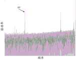
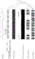
图2和图3分别为绘制AIS负载和伪随机比特序列(pseudo random bit sequence,PRBS)负载的频谱图。离散音取决于负载和发射机波特率等。在实践中,特别是对于携带了AIS、OCI、和LCK负载的信号,通过选择无干扰的导频音(pilot tone,PT)频率来避免这些离散音是极其困难的,这是因为,存在太多不同的波特率(包括时钟漂移)、FEC码字、以及DSP帧结构等。FIG. 2 and FIG. 3 are spectrograms for plotting the AIS load and the pseudo random bit sequence (pseudo random bit sequence, PRBS) load, respectively. Discrete tone depends on load and transmitter baud rate etc. In practice, especially for signals carrying AIS, OCI, and LCK loads, it is extremely difficult to avoid these discrete tones by choosing a pilot tone (PT) frequency without interference, because there are too many Many different baud rates (including clock drift), FEC codewords, and DSP frame structures, etc.
为了提供用于监测光网络的性能的低成本、高效率的解决方案,需要一种克服了由离散干扰引起的问题的改进的调制和检测技术。In order to provide a low-cost, high-efficiency solution for monitoring the performance of optical networks, there is a need for an improved modulation and detection technique that overcomes the problems caused by discrete interference.
发明内容SUMMARY OF THE INVENTION
为了提供对本发明的基本理解,以下给出本发明某些方面或实施例的简化概述。该概述不是对本发明的广泛综述。该概述并非旨在确定本公开的核心要素或关键要素,也并非旨在划出本发明的保护范围。其唯一目的是以简化的形式呈现本发明的一些实施例,作为之后更详细描述的序言。In order to provide a basic understanding of the invention, the following presents a simplified summary of certain aspects or embodiments of the invention. This summary is not an extensive overview of the invention. This summary is not intended to identify core or critical elements of the disclosure, nor is it intended to delineate the scope of the invention. Its sole purpose is to present some embodiments of the invention in a simplified form as a prelude to the more detailed description that is presented later.
本说明书公开了一种利用抗干扰扩频导频音的光性能监测技术。This specification discloses an optical performance monitoring technology using anti-jamming spread spectrum pilot tones.
本公开的一个方面为一种监测光网络中的光信道的系统。该系统包括光发射机和光接收机。光发射机具有扩频导频音调制器,该扩频导频音调制器用于将扩频导频音调制到高速数据信号上以生成扩频光信号;光接收机用于接收上述扩频光信号,并用于检测上述导频音以监测该光信道。One aspect of the present disclosure is a system for monitoring optical channels in an optical network. The system includes an optical transmitter and an optical receiver. The optical transmitter has a spread-spectrum pilot tone modulator, which is used to modulate the spread-spectrum pilot tone on the high-speed data signal to generate a spread-spectrum optical signal; the optical receiver is used to receive the above-mentioned spread-spectrum light signal and is used to detect the above-mentioned pilot tones to monitor the optical channel.
本公开的另一个方面为一种监测光网络中的光信道的方法。该方法需要将扩频导频音调制到高速数据信号上以生成扩频信号,通过光链路发送该扩频信号,接收该扩频信号,并在该扩频信号中检测上述导频音来监测光信道。Another aspect of the present disclosure is a method of monitoring an optical channel in an optical network. The method requires modulating a spread spectrum pilot tone onto a high-speed data signal to generate a spread spectrum signal, sending the spread spectrum signal through an optical link, receiving the spread spectrum signal, and detecting the pilot tone in the spread spectrum signal to generate a spread spectrum signal. Monitor the optical channel.
本公开的又一个方面为一种光发射机,该光发射机具有用于接收数据信号的输入端、用于将扩频导频音调制到上述数据信号上从而生成数字扩频数据信号的导频音调制器、用于将上述数字扩频数据信号转换为模拟扩频数据信号的数-模转换器、以及用于将上述模拟扩频数据信号转换为用于传输的光扩频数据信号的电-光转换器。Yet another aspect of the present disclosure is an optical transmitter having an input for receiving a data signal, a pilot for modulating a spread spectrum pilot tone onto the data signal to generate a digital spread spectrum data signal Tone modulator, digital-to-analog converter for converting said digital spread spectrum data signal into analog spread spectrum data signal, and for converting said analog spread spectrum data signal into optical spread spectrum data signal for transmission Electro-optical converter.
本公开的再一个方面为一种光接收机,该光接收机具有用于接收光扩频数据信号的输入端、光电二极管、模-数转换器、以及具有用于执行相关计算以检测数据信号中的导频音的相关模块(correlation module)的检测器。可利用预定义的扩频编码函数(例如,由光发射机用于将扩频导频音调制到数据信号上的编码函数)来执行该相关计算。Yet another aspect of the present disclosure is an optical receiver having an input for receiving an optical spread spectrum data signal, a photodiode, an analog-to-digital converter, and a device for performing correlation calculations to detect the data signal The detector of the correlation module of the pilot tones in . This correlation calculation may be performed using a predefined spread spectrum coding function (eg, the coding function used by the optical transmitter to modulate the spread spectrum pilot tones onto the data signal).
附图说明Description of drawings
参考以下附图的描述,本公开的这些特征和其它特征将变得更加明显。These and other features of the present disclosure will become more apparent with reference to the following description of the accompanying drawings.
图1描绘了具有用于监测光网络的光链路的光性能的多个导频音检测器的光网络。Figure 1 depicts an optical network with multiple pilot tone detectors for monitoring the optical performance of the optical links of the optical network.
图2为示出在AIS负载中的连续波导频音的频谱图。Figure 2 is a spectrogram showing continuous wave pilot tones in an AIS load.
图3为示出在PRBS负载中的连续波导频音的频谱图。Figure 3 is a spectrogram showing continuous wave pilot tones in a PRBS load.
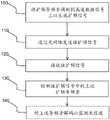
图4为示出监测光性能的方法的流程图。4 is a flow chart illustrating a method of monitoring light performance.
图5为连续波导频音的频谱图的示例。5 is an example of a spectrogram of a continuous wave pilot tone.
图6为扩频导频音的频谱图的示例。6 is an example of a spectrogram of a spread spectrum pilot tone.
图7为恢复的导频音的频谱图的示例。7 is an example of a spectrogram of recovered pilot tones.
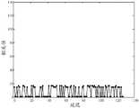
图8为示出m1*m1相关性的图,其中m1表示27-1位的伪随机比特序列。FIG. 8 is a graph showing the correlation of m1 *m1 , where m1 represents a pseudo-random bit sequence of 27 −1 bits.
图9为示出m1*m2相关性的图,其中m1和m2表示两个27-1位的伪随机比特序列。FIG. 9 is a graph showing the correlation of m1 *m2 , where m1 and m2 represent two pseudo-random bit sequences of 27 −1 bits.
图10为示出具有显著干扰音的扩频导频音的频谱图。FIG. 10 is a spectrogram showing a spread spectrum pilot tone with a prominent interfering tone.
图11为示出恢复后的导频音的频谱图,其中,干扰音的频谱已被分布到本底噪声中。Figure 11 is a spectrogram showing the recovered pilot tones, where the spectrum of the interfering tones has been distributed into the noise floor.
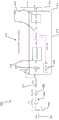
图12示出了扩频导频音调制技术中的各种形式的信号的六个垂直对齐的图形表示。12 shows six vertically aligned graphical representations of various forms of signals in the spread spectrum pilot tone modulation technique.
图13描绘了具有扩频导频音调制器的光发射机。Figure 13 depicts an optical transmitter with a spread spectrum pilot tone modulator.
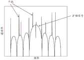
图14为示出了九个信道的九个相邻导频音的频谱图。Figure 14 is a spectrogram showing nine adjacent pilot tones for nine channels.
图15示出了作为第一种实施方式和第二实施方式的信道间隔的函数的串扰的图,在第一种实施方式中,PRBS全部相同,在第二种实施方式中,PRBS均不相同。Figure 15 shows a graph of crosstalk as a function of channel spacing for a first embodiment where the PRBSs are all the same, and a second embodiment where the PRBSs are all different .
图16描绘了用于检测和解码导频音的光接收机。Figure 16 depicts an optical receiver for detecting and decoding pilot tones.
具体实施方式Detailed ways
为了说明的目的,以下详细描述包含许多具体实施例、实施方式、示例以及细节,以提供对本发明的深入理解。然而,显而易见的是,可以在没有这些具体细节或在具有等同安排的情况下实施上述实施例。在其他情况下,以框图形式示出了一些众所周知的结构和设备,以避免不必要地模糊本发明的实施例。该描述不应限于以下阐述的说明性的实施方式、附图、以及技术,包括本文所示出和描述的示例性设计和实施方式,而是可以在所附权利要求的范围及其等同物的全部范围内被修改。For purposes of explanation, the following detailed description contains numerous specific embodiments, implementations, examples, and details in order to provide a thorough understanding of the present invention. It will be apparent, however, that the above-described embodiments may be practiced without these specific details or with an equivalent arrangement. In other instances, well-known structures and devices are shown in block diagram form in order to avoid unnecessarily obscuring embodiments of the present invention. This description should not be limited to the illustrative embodiments, drawings, and techniques set forth below, including the exemplary designs and embodiments shown and described herein, but is intended to be included within the scope of the appended claims and their equivalents The entire range has been modified.
本文公开了一种使用扩频导频音执行光性能监测的方法和一种使用扩频导频音执行光性能监测的系统。使用超过连续波导频音带宽的带宽来发送扩频导频音。在大带宽上扩展(或“分布”)上述导频音可以使得生成的扩频导频音更能抵抗干扰。因此,扩频导频音更容易被光网络中的导频音检测器检测。Disclosed herein is a method for performing optical performance monitoring using spread spectrum pilot tones and a system for performing optical performance monitoring using spread spectrum pilot tones. The spread spectrum pilot tones are sent using a bandwidth that exceeds the bandwidth of the CW pilot tone. Spreading (or "distributing") the pilot tones over a large bandwidth can make the generated spread-spectrum pilot tones more resistant to interference. Therefore, the spread spectrum pilot tone is more easily detected by the pilot tone detector in the optical network.
图4描绘了流程图,其大体上阐述了光性能监测的方法。该方法通常涉及将扩频编码函数应用于连续波导频音,以便在不易受干扰的扩展频带上分布导频音。随后由导频音检测器检测(可选地,还解码)上述导频音。如图4所示,该方法包括:将扩频导频音调制100到高速数据信号上以生成扩频信号,通过光网络发送110该扩频信号,接收120该扩频信号,检测130该扩频信号中的上述扩频导频音。可选地,该方法可以包括对上述导频音进行解码140以监测光信道的另一步骤。需要强调的是,可同时接收120多于一个扩频信号。波长(每个都携带其自己的导频音)可以来自光网络中的相同节点或不同节点。Figure 4 depicts a flow diagram that generally illustrates the method of optical performance monitoring. The method typically involves applying a spread-spectrum coding function to continuous-wave pilot tones in order to distribute the pilot tones over an extended frequency band that is less susceptible to interference. Said pilot tones are then detected (and optionally also decoded) by a pilot tone detector. As shown in FIG. 4 , the method includes: modulating 100 a spread spectrum pilot tone onto a high-speed data signal to generate a spread spectrum signal, sending 110 the spread spectrum signal through an optical network, receiving 120 the spread spectrum signal, and detecting 130 the spread spectrum signal the above-mentioned spread spectrum pilot tone in the frequency signal. Optionally, the method may comprise the further step of decoding 140 the above-mentioned pilot tones to monitor the optical channel. It should be emphasized that more than one spread spectrum signal can be received 120 simultaneously. The wavelengths, each carrying its own pilot tone, can come from the same node or different nodes in the optical network.
对于具有给定角频率ωPT、调制深度m、以及带内二进制数据(即导频音数据d(t))的常规连续波导频音,上述高速光数据信号的电场E0(t用上述导频音调制如下,以提供由以下关系式给出的调制信号的电场EPT(t):EPT(t)=E0(t)(1+d(t)msin(ωPTt))。图5示出了连续波导频音的频谱图的一个具体示例。For a conventional CW pilot tone with a given angular frequency ωPT , modulation depth m, and in-band binary data (ie, pilot tone data d(t)), the electric field E0 (t) of the above-mentioned high-speed optical data signal is determined by the above-mentioned guide The tone is modulated as follows to provide the electric field EPT (t) of the modulated signal given by the relation: EPT (t)=E0 (t)(1+d(t)msin(ωPT t)). FIG. 5 shows a specific example of a spectrogram of a continuous wave pilot tone.
对于扩频导频音,通过运用扩频码fESC(t)来调制信号。换句话说,通过如下将扩频码fESC(t)运用于导频音来完成调制:EPT(t)=E0(t)(1+d(t)fESC(t)msin(ωPTt))。在一个实施例中,fESC(t)是,或包括伪随机比特序列(PRBS),但是应当理解,可以使用其他等效或合适的码字。还要注意的是,fESC(t)的带宽通常远大于d(t),但远小于E0(t)。图6示出了扩频导频音的频谱图的一个具体示例。图7示出了恢复的导频音的频谱图的一个具体示例。具有时变电场EPT(t)的调制信号之后通过光网络的一个或多个光链路被发送到网络的一个或多个节点。在网络中的各个位置,可以放置导频音检测器(PTD)来测量和监测光性能。在一个实施例中,导频音检测器实施了平方律检测技术来检测导频音。由于导频音是比高速数据信号频率低的信号,导频音检测器可以使用低速光电二极管来检测导频音。时变电流I(t)由关系式I(t)=|E0(t)|2(1+2d(t)fESC(t)msin(ωPTt)+|d(t)fESC(t)msin(ωPTt)|2)给出。由于E0(t)对于低速光电二极管来说过于快速,因此上述电流可以由I(t)≈I0(1+2d(t)fESC(t)msin(ωPTt))表示。由于只保留了包含调制的项,因此该关系式可以表示为I(t)≈I0 2d(t)fESC(t)msin(ωPTt)。For spread spectrum pilot tones, the signal is modulated by applying a spreading codefESC (t). In other words, modulation is accomplished by applying the spreading codefESC (t) to the pilot tone as follows: EPT(t)= E0(t)(1+d(t)fESC (t)msin (ωPT t)). In one embodiment,fESC (t) is, or includes, a pseudo-random bit sequence (PRBS), although it should be understood that other equivalent or suitable codewords may be used. Also note that the bandwidth offESC (t) is usually much larger than d(t), but much smaller than E0( t). FIG. 6 shows a specific example of a spectrogram of a spread spectrum pilot tone. FIG. 7 shows a specific example of a spectrogram of the recovered pilot tones. The modulated signal with the time-varying electric field EPT (t) is then sent to one or more nodes of the network via one or more optical links of the optical network. At various locations in the network, pilot tone detectors (PTDs) can be placed to measure and monitor optical performance. In one embodiment, the pilot tone detector implements a square-law detection technique to detect pilot tones. Since the pilot tone is a lower frequency signal than the high speed data signal, the pilot tone detector can use a low speed photodiode to detect the pilot tone. The time-varying current I(t) is given by the relation I(t)=|E0 (t)|2 (1+2d(t)fESC (t)msin(ωPT t)+|d(t)fESC ( t) msin(ωPT t)|2 ) is given. Since E0 (t) is too fast for a low-speed photodiode, the above current can be represented by I(t)≈I0 (1+2d(t)fESC (t)msin(ωPT t)). Since only the terms containing modulation are retained, this relation can be expressed as I(t)≈
通过使用相关器或相关模块执行相关运算来完成解码,相关器或相关模块如下使用相同的扩频码fESC(t):I0 2d(t)fESC(t)msin(ωPTt)*fESC(t),其中,*是相关运算符。然而,由于fESC(t)*fESC(t)的峰值是强且已知的,因此该相关性峰值与I0(t)2d(t)fESCmsin(ωPTt)成比例。如果没有信号,则相关性峰值要小得多。例如,考虑从27-1位的PRBS派生出的如下两个序列m1和m2:m1:-1 -1 -1 -1 -1 -1 1 1 1 1 1 1 1 -1 1 -1 1 -1 1 -1 -1 1 1 -1-1 1 1 1 -1 1 1 1 -1 1 -1 -1 1 -1 1 1 -1 -1 -1 1 1 -1 1 1 1 1 -1 1 1 -1 1 -11 1 -1 1 1 -1 -1 1 -1 -1 1 -1 -1 -1 1 1 1 -1 -1 -1 -1 1 -1 1 1 1 1 1 -1 -1 1-1 1 -1 1 1 1 -1 -1 1 1 -1 1 -1 -1 -1 1 -1 -1 1 1 1 1 -1 -1 -1 1 -1 1 -1 -1 -1 -1 1 1 -1 -1 -1 -1 -1 1Decoding is done by performing a correlation operation using a correlator or correlation block that uses the same spreading codefESC (t) as follows: I0 2d(t)fESC (t)msin(ωPT t)* fESC (t), where * is the correlation operator. However, since the peak of fESC (t)*fESC (t) is strong and known, this correlation peak is proportional to I0 (t)2d(t)fESC msin(ωPT t). If there is no signal, the correlation peak is much smaller. For example, consider the following two sequences m1 and m2 derived from a PRBS of 27 -1 bits: m1: -1 -1 -1 -1 -1 -1 1 1 1 1 1 1 1 -1 1 -1 1 -1 1 -1 -1 1 1 -1-1 1 1 1 -1 1 1 1 -1 1 -1 -1 1 -1 1 1 -1 -1 -1 1 1 -1 1 1 1 1 -1 1 1 -1 1 -11 1 -1 1 1 -1 -1 1 -1 -1 1 -1 -1 -1 1 1 1 -1 -1 -1 -1 1 -1 1 1 1 1 1 -1 - 1 1-1 1 -1 1 1 1 -1 -1 1 1 -1 1 -1 -1 -1 1 -1 -1 1 1 1 1 -1 -1 -1 1 -1 1 -1 -1 -1 -1 1 1 -1 -1 -1 -1 -1 1
m2:-1 -1 -1 -1 -1 -1 1 -1 -1 1 -1 -1 1 1 -1 1 -1 -1 1 1 1 1 -1 1 1 1-1 -1 -1 -1 1 1 1 1 1 1 1 -1 -1 -1 1 1 1 -1 1 1 -1 -1 -1 1 -1 1 -1 -1 1 -1 11 1 1 1 -1 1 -1 1 -1 1 -1 -1 -1 -1 1 -1 1 1 -1 1 1 1 1 -1 -1 1 1 1 -1 -1 1 -11 -1 1 1 -1 -1 1 1 -1 -1 -1 -1 -1 1 1 -1 1 1 -1 1 -1 1 1 1 -1 1 -1 -1 -1 1 1-1 -1 1 -1 -1 -1 1m2:-1 -1 -1 -1 -1 -1 1 -1 -1 1 -1 -1 1 1 -1 1 -1 -1 1 1 1 1 -1 1 1 1-1 -1 -1 -1 1 1 1 1 1 1 1 -1 -1 -1 1 1 1 -1 1 1 -1 -1 -1 1 -1 1 -1 -1 1 -1 11 1 1 1 -1 1 -1 1 -1 1 -1 -1 -1 -1 1 -1 1 1 -1 1 1 1 1 -1 -1 1 1 1 -1 -1 1 -11 -1 1 1 -1 -1 1 1 -1 -1 -1 - 1 -1 1 1 -1 1 1 -1 1 -1 1 1 1 -1 1 -1 -1 -1 1 1-1 -1 1 -1 -1 -1 1
图8为示出了m1*m1相关性的图。值得注意的是,在0延迟处存在强峰,其峰值振幅为127。图9为示出了m1*m2相关性的图,图中没有强峰。FIG. 8 is a graph showing the m1 *m1 correlation. Notably, there is a strong peak at 0 delay with a peak amplitude of 127. FIG. 9 is a graph showing the m1 *m2 correlation without strong peaks.
通过使用这种扩频方法,可以在显著干扰的条件下检测导频音,否则,使用现有技术在显著干扰的条件下检测导频音是非常困难的。本文公开的扩频方法使得导频音更容易恢复,从而有助于光网络中的光性能监测。例如,图10描绘了示出具有显著干扰音的扩频导频音的频谱图。如图11中的示例所示,在解码之后,导频音被恢复,而干扰音的频谱被分布到本底噪声中。By using this spread spectrum method, it is possible to detect pilot tones under conditions of significant interference that would otherwise be very difficult to detect under conditions of significant interference using existing techniques. The spread spectrum method disclosed herein enables easier recovery of pilot tones, thereby facilitating optical performance monitoring in optical networks. For example, FIG. 10 depicts a spectrogram showing spread spectrum pilot tones with prominent interfering tones. As shown in the example in Figure 11, after decoding, the pilot tones are recovered and the spectrum of the interfering tones are distributed into the noise floor.
图12示出了可用于光性能监测的扩频导频音调制技术的具体示例。图12示出了各种形式的信号的六个垂直对齐的图形表示。顶部是由函数d(t)表示的导频音(PT)比特序列。在该示例中,d(t)为101101。导频音比特序列d(t)例如可以为识别或表征信道的数据。通过运用扩频码fESC(t)来调制函数d(t),在该实例中,扩频码fESC(t)为PRBS,例如1111100110100100001010111011000。在本例中,PRBS的长度为25-1。在其他实施例中,PRBS的长度可以变化。图12还在顶部起第三个表示示出了具有形式sin(ωPTt)的连续波(continuous wave,CW)PT。该CW PT可以具有调制深度m,在这种情况下,CW PT可以表示为msin(ωPTt)。如图12中的箭头所示,PT比特序列d(t)、扩频码fESC(t)、和CW PT被混合在一起,以提供图12所示的由顶部起第五个信号,其在数学上被描述为这三个信号的乘积,即,d(t)fESC(t)sin(ωPTt)。第六个信号表示,即图12底部的表示,即,fESC(t)sin(ωPTt),是通过仅混合扩频码fESC(t)和CW PT产生的,即省略了PT比特序列d(t)。由顶部起的第四个信号表示示出了高速数据和叠加在高速数据上的扩频导频音。Figure 12 shows a specific example of a spread spectrum pilot tone modulation technique that can be used for optical performance monitoring. Figure 12 shows six vertically aligned graphical representations of various forms of signals. On top is the pilot tone (PT) bit sequence represented by the function d(t). In this example, d(t) is 101101. The pilot tone bit sequence d(t) may be, for example, data identifying or characterizing the channel. The function d(t) is modulated by applying a spreading codefESC (t), which in this example is a PRBS, eg,1111100110100100001010111011000 . In this example, the length of the PRBS is 25 -1. In other embodiments, the length of the PRBS may vary. Figure 12 also shows a continuous wave (CW) PT of the form sin(ωPT t) in the third representation from the top. The CW PT may have a modulation depth m, in which case the CW PT may be expressed as msin(ωPT t). As indicated by the arrows in Figure 12, the PT bit sequence d(t), spreading codefESC (t), and CW PT are mixed together to provide the fifth signal from the top shown in Figure 12, which Mathematically described as the product of these three signals, ie, d(t)fESC (t)sin(ωPT t). The sixth signal representation, the representation at the bottom of Figure 12, i.e.,fESC (t)sin(ωPT t), is generated by mixing only the spreading codesfESC (t) and CW PT, i.e. omitting the PT bit The sequence d(t). The fourth signal representation from the top shows the high speed data and the spread spectrum pilot tone superimposed on the high speed data.
在通过图13中的示例描绘的实施例中,光发射机200包括承载高速数据信号E0(t)的高速数据信号输入端210、扩频导频音调制器220、数-模(digital-to-analog,DAC)转换器230以及电-光(electrical-to-optical,E/O)转换器240。光发射机通过光链路250发送调制后的光信号。对于基于正交的调制方案,将存在四个这样的单元。在图13中,变量m表示调制深度,ωPT(t)表示导频音角频率,以及fESC(t)表示扩频编码函数。在一个实施例中,该编码函数可以是具有值为1,0或1,-1的PRBS。函数d(t)表示导频音数据,在本实施例中为二进制数据(1,0)。在图13所示的实施例中,调制器220包括连续波(CW)导频音发生器260、扩频码函数发生器270、以及用于将CW导频音与编码函数混合以生成调制后的扩频导频音的第一混频器275。调制器220还包括PT数据发生器280以及用于将PT数据d(t)与上述调制后的扩频导频音混合的第二混频器285。调制器220还包括加法模块290,用于将函数加常数值1。调制器220还包括用于将导频音调制到高速数据信号上的第三混频器225。需要注意的是,在发射机200中,可能存在不止一条高速数据/DAC路径,例如,在典型的相干发射机中,存在四条路径,在这种情况下,上述扩频导频音可应用于所有四条路径。In the embodiment depicted by the example in FIG. 13, the
如图14中的示例所示,在具有多个信道的实施方式中,这些信道的扩展频谱可能部分地彼此重叠,这可能引入串扰。例如,在图14所示的示例中,存在九个相邻导频音,每个信道一个导频音。尽管在图14中示出了九个导频音,但是应当理解,导频音的数量是可以改变的。应当注意的是,图14中的信道不是光信道,而是调制后的导频音的频谱。为了减少相邻信道干扰,即减轻串扰,不同的码字(例如,不同的PRBS码)可用于相邻信道。例如,通过使用两倍于扩频码率(即,2fc)的信道间隔,并且通过使用不同的PRBS码,如图15所示,举例来说,可以抑制大约14dB的串扰。还可以理解的是,用于各个信道的不同扩频码可以是异步的。此外,应当理解,窄带扩频是理想的,这是因为,已经发现窄带扩频减少了信道串扰。在图14中,九个信道上的九个导频音可以具有例如ΔfPT=100kHz的信道间隔,以及具有例如f=50kHz的信道带宽。因为f<ΔfPT,因此这是一个窄带扩频的示例。As shown in the example in Figure 14, in embodiments with multiple channels, the spread spectrum of these channels may partially overlap each other, which may introduce crosstalk. For example, in the example shown in Figure 14, there are nine adjacent pilot tones, one pilot tone per channel. Although nine pilot tones are shown in Figure 14, it should be understood that the number of pilot tones may vary. It should be noted that the channels in Figure 14 are not optical channels, but rather the spectrum of the modulated pilot tones. To reduce adjacent channel interference, ie to mitigate crosstalk, different codewords (eg, different PRBS codes) may be used for adjacent channels. For example, by using a channel spacing twice the spreading code rate (ie, 2fc ), and by using a different PRBS code, as shown in FIG. 15 , for example, about 14 dB of crosstalk can be suppressed. It will also be appreciated that the different spreading codes used for each channel may be asynchronous. Furthermore, it should be understood that narrowband spread spectrum is desirable because narrowband spread spectrum has been found to reduce channel crosstalk. In Figure 14, the nine pilot tones on nine channels may have a channel spacing of eg ΔfPT = 100 kHz, and a channel bandwidth of eg f = 50 kHz. Since f<ΔfPT , this is an example of narrowband spread spectrum.
在图16的实例所示的实施例中,光接收机300接收、检测、并解码上述导频音以恢复PT比特序列d(t)。光接收机300包括光输入端(光链路)302、光电二极管(photodiode,PD)304、互阻抗放大器(transimpedance amplifier,TIA)306、运算放大器(operationalamplifier,op-amp)308,即AC耦合的高增益电子电压放大器、用于数字化模拟电信号的模-数转换器(analog-to-digital converter,ADC)310、以及包括用于多个信道的多个检测器314的多信道检测单元312。在该实施例中,每个信道有一个检测器314。在图16的实施例中,每个检测器314包括混频器316,用于将来自ADC 310的信号与向下移位因子324混合以将信号频率下移至DC附近。每个检测器314还包括时域相关器(或“时域相关模块”)318和用于确定频率扫描是否已经完成的判定块320。如果扫描完成,则下一步将是提取PT功率。否则,该方法通过递增或递减向下移位因子324的角频率ω继续扫描频率。光接收机300包括PT功率处理模块322,该PT功率处理模块322用于在频率扫描完成之后,从最大相关峰值中提取光功率。In the embodiment shown in the example of FIG. 16, the
为了检测特定的扩频导频音,导频音频率和扩频码相位均必须匹配。这可以通过执行以下步骤来实现:在第一步中,在一个完整的ESC持续时间TESC收集数据。在第二步中,对于ω~ωPT,频率向下移动ω到DC附近。在第三步中,使用相同的ESC执行时域相关计算。记录相关性峰值。随后,以不同的频率ω重复第二步和第三步以找到最大峰值。应当注意的是,频率扫描范围由导频音发生器260和检测器314之间的最大时钟差和导频音频率决定。频率扫描的步长由TESC确定,使得步长远小于1/TESC以满足精度要求。In order to detect a specific spread spectrum pilot tone, both the pilot tone frequency and the spreading code phase must match. This can be achieved by performing the following steps: In the first step, data is collected over a full ESC duration TESC . In the second step, the frequency is shifted down by ω to around DC for ω ~ ωPT . In the third step, time domain correlation calculations are performed using the same ESC. Record correlation peaks. Subsequently, the second and third steps are repeated with different frequencies ω to find the maximum peak. It should be noted that the frequency sweep range is determined by the maximum clock difference between the
从上述可以理解,与连续波导频音相比,扩频导频音使DWDM系统中的光性能监测更耐强离散干扰。在本文公开的实施例中,每个波长信道具有唯一的导频音。As can be understood from the above, the spread spectrum pilot tone makes the optical performance monitoring in the DWDM system more resistant to strong discrete interference compared to the continuous wave pilot tone. In the embodiments disclosed herein, each wavelength channel has a unique pilot tone.
在一种实施方式中,导频音具有在大约1-100MHz范围内的频率ωPT,而扩频编码函数fESC(t)具有在1-100kHz范围内的频率。在更具体的实施方式中,导频音具有在约10-99MHz范围内的频率ωPT,而扩频编码函数fESC(t)具有在10-99kHz范围内的频率。在更具体的实施方式中,导频音具有在大约30-60MHz范围内的频率ωPT,而扩频编码函数fESC(t)具有在30-60kHz范围内的频率。In one embodiment, the pilot tone has a frequency ωPT in the range of approximately 1-100 MHz, and the spread spectrum encoding functionfESC (t) has a frequency in the range of 1-100 kHz. In a more specific embodiment, the pilot tone has a frequency ωPT in the range of about 10-99 MHz, and the spread spectrum encoding function fESC (t) has a frequency in the range of 10-99 kHz. In a more specific embodiment, the pilot tone has a frequency ωPT in the range of approximately 30-60 MHz, and the spread spectrum encoding function fESC (t) has a frequency in the range of 30-60 kHz.
在另一种实施方式中,本文描述的扩频导频音技术可以与频分复用相结合,以进一步减少相邻PT信道之间的串扰。例如,第一信道的第一导频音可以在30MHz,第二信道的第二导频音在30MHz+100kHz,第三导频音在30MHz+200kHz,第四导频音在30MHz+300kHz,等。In another embodiment, the spread spectrum pilot tone techniques described herein may be combined with frequency division multiplexing to further reduce crosstalk between adjacent PT channels. For example, the first pilot tone of the first channel may be at 30MHz, the second pilot tone of the second channel may be at 30MHz+100kHz, the third pilot tone may be at 30MHz+200kHz, the fourth pilot tone may be at 30MHz+300kHz, etc. .
虽然在本公开中已经提供了几个实施例,但是应当理解,在不脱离本公开的范围的情况下,所公开的系统和方法可以通过许多其它具体形式实施。本示例应当被认为是说明性的而不是限制性的,并且其意图不限于本文给出的细节。例如,各种元件或组件可以组合或集成在另一系统中,或者某些特征可以被省略或不被实施。While several embodiments have been presented in the present disclosure, it should be understood that the disclosed systems and methods may be embodied in many other specific forms without departing from the scope of the present disclosure. This example should be considered illustrative rather than restrictive, and it is not intended to be limited to the details given herein. For example, various elements or components may be combined or integrated in another system, or certain features may be omitted or not implemented.
此外,在不脱离本公开的范围的情况下,在各种实施例中描述和示出为离散或分离的技术、系统、子系统以及方法可以与其他系统、模块、技术或方法组合或集成。示出或讨论为耦合或直接耦合或相连的其他项目可以通过某些接口、设备或中间组件以电连接、机械连接或是其他方式间接耦合或相连。本领域技术人员在不脱离本文公开的发明构思的情况下可以确定改变、替换、和变更的其它示例。Furthermore, techniques, systems, subsystems and methods described and illustrated in various embodiments as discrete or separate may be combined or integrated with other systems, modules, techniques or methods without departing from the scope of the present disclosure. Other items shown or discussed as coupled or directly coupled or connected may be electrically, mechanically, or otherwise indirectly coupled or connected through certain interfaces, devices, or intermediate components. Those skilled in the art may ascertain other examples of changes, substitutions, and alterations without departing from the inventive concepts disclosed herein.
Claims (21)
Translated fromChineseApplications Claiming Priority (1)
| Application Number | Priority Date | Filing Date | Title |
|---|---|---|---|
| PCT/CN2016/074144WO2017139974A1 (en) | 2016-02-19 | 2016-02-19 | Optical channel monitoring using expanded-spectrum pilot tone |
Publications (2)
| Publication Number | Publication Date |
|---|---|
| CN108702208A CN108702208A (en) | 2018-10-23 |
| CN108702208Btrue CN108702208B (en) | 2020-07-24 |
Family
ID=59624713
Family Applications (1)
| Application Number | Title | Priority Date | Filing Date |
|---|---|---|---|
| CN201680081541.9AActiveCN108702208B (en) | 2016-02-19 | 2016-02-19 | Optical channel monitoring using spread spectrum pilot tones |
Country Status (3)
| Country | Link |
|---|---|
| US (2) | US10148351B2 (en) |
| CN (1) | CN108702208B (en) |
| WO (1) | WO2017139974A1 (en) |
Families Citing this family (9)
| Publication number | Priority date | Publication date | Assignee | Title |
|---|---|---|---|---|
| CN108781113B (en)* | 2016-06-24 | 2020-03-20 | 华为技术有限公司 | Method and apparatus for providing pilot tones |
| US10523315B2 (en) | 2017-04-05 | 2019-12-31 | Huawei Technologies Co., Ltd. | Systems and method of multi-band pilot tone based optical performance monitoring |
| US10348438B2 (en)* | 2017-09-04 | 2019-07-09 | Huawei Technologies Co., Ltd. | Spur removal in pilot-tone OPM |
| WO2022024293A1 (en)* | 2020-07-30 | 2022-02-03 | 日本電信電話株式会社 | Optical transmission system and transmission quality monitoring method |
| EP4096118A1 (en)* | 2021-05-28 | 2022-11-30 | ADVA Optical Networking SE | Method for determining actual values of one or more characteristics of a phase-modulated optical signal |
| US11716138B2 (en)* | 2021-10-18 | 2023-08-01 | Huawei Technologies Co., Ltd. | Systems and methods for monitoring generalized optical signal-to-noise ratio |
| CN116961768A (en)* | 2022-04-20 | 2023-10-27 | 武汉光迅科技股份有限公司 | Method and system for sending and receiving multi-mode roof-adjusting signal |
| US12267105B2 (en)* | 2023-01-30 | 2025-04-01 | Huawei Technologies Co., Ltd. | System and method for monitoring optical performance in a spatial division multiplexing system |
| CN117061011A (en)* | 2023-08-17 | 2023-11-14 | 中天通信技术有限公司 | Optical module with roof adjusting function and data transmission system |
Citations (2)
| Publication number | Priority date | Publication date | Assignee | Title |
|---|---|---|---|---|
| CN101106424A (en)* | 2006-07-11 | 2008-01-16 | 阿尔卡特朗讯公司 | Method and device for monitoring optical connection channels of a transmission optical network |
| CN102771067A (en)* | 2009-12-21 | 2012-11-07 | 诺基亚西门子通信公司 | Method and apparatus for preventing signal interference in a passive optical network |
Family Cites Families (21)
| Publication number | Priority date | Publication date | Assignee | Title |
|---|---|---|---|---|
| EP0772314A3 (en)* | 1990-09-14 | 1997-09-03 | Fujitsu Ltd | Optical communication system with sub-carrier multiplexing |
| US5459758A (en)* | 1993-11-02 | 1995-10-17 | Interdigital Technology Corporation | Noise shaping technique for spread spectrum communications |
| SE523374C2 (en)* | 1997-07-31 | 2004-04-13 | Ericsson Telefon Ab L M | Communication using spectrum spreading methods over optical fibers |
| KR100317806B1 (en)* | 1999-03-19 | 2001-12-22 | 서평원 | Apparatus and method for detecting information of optical transmission channel using spread spectrum code modulation |
| US6538789B2 (en)* | 2001-04-03 | 2003-03-25 | Lightwave Solutions, Inc. | Optical linearizer for fiber communications |
| US6970651B1 (en)* | 2001-07-31 | 2005-11-29 | Terabeam Corporation | High-sensitivity tracking in free-space optical communication systems |
| US20030043437A1 (en)* | 2001-09-04 | 2003-03-06 | Stough Stephen A. | Subliminal coherent phase shift keyed in-band signaling of network management information in wavelength division multiplexed fiber optic networks |
| US20030180055A1 (en)* | 2002-03-22 | 2003-09-25 | Kameran Azadet | Optically calibrated pulse amplitude modulated transmission scheme for optical channels |
| US20050019040A1 (en)* | 2003-07-24 | 2005-01-27 | Trutna William R. | Optical communication system and method using spread-spectrum encoding |
| CN1581756A (en)* | 2003-08-06 | 2005-02-16 | 华为技术有限公司 | Optical modulating transmission method and system |
| US7590351B2 (en)* | 2005-09-15 | 2009-09-15 | Finisar Corporation | Extinction ratio control using a frequency spread tone to modulate optical signal power levels |
| ES2372413T3 (en)* | 2006-05-12 | 2012-01-19 | Gigaset Communications Gmbh | PROCEDURE FOR THE SENDING OF DATA OPTIMALLY TRANSMITTED THROUGH A RADIO ANTENNA AND THE CORRESPONDING DEVICE. |
| JP5130702B2 (en)* | 2006-12-05 | 2013-01-30 | 富士通株式会社 | Polarization orthogonal controller |
| JP4839266B2 (en)* | 2007-06-07 | 2011-12-21 | 株式会社日立製作所 | Optical communication system |
| US8078054B2 (en)* | 2008-06-30 | 2011-12-13 | Alcatel Lucent | Apparatus and method for improving the tolerance of tone-based optical channel monitoring to stimulated Raman scattering |
| CN101714907B (en)* | 2009-12-22 | 2013-01-23 | 北京邮电大学 | Passive optical network communication method, passive optical network communication system, optical network unit and optical line terminal |
| US20120288274A1 (en)* | 2011-05-15 | 2012-11-15 | Wen Li | Optical network system and devices enabling data, diagnosis, and management communications |
| JP5924088B2 (en)* | 2012-04-06 | 2016-05-25 | 富士通株式会社 | Optical transmission system |
| US8849129B2 (en)* | 2012-07-20 | 2014-09-30 | Finisar Corporation | Method and apparatus for stabilization of optical transmitter |
| JP6060608B2 (en)* | 2012-10-12 | 2017-01-18 | 富士通株式会社 | Optical transmission system, optical transmission device inspection method, and optical transmission device inspection program |
| US9270370B2 (en)* | 2014-01-29 | 2016-02-23 | Huawei Technologies Co., Ltd. | System and method for pilot tone modulation by data bias |
- 2016
- 2016-02-19CNCN201680081541.9Apatent/CN108702208B/enactiveActive
- 2016-02-19WOPCT/CN2016/074144patent/WO2017139974A1/ennot_activeCeased
- 2016-03-18USUS15/074,243patent/US10148351B2/enactiveActive
- 2018
- 2018-06-20USUS16/013,124patent/US10469163B2/enactiveActive
Patent Citations (2)
| Publication number | Priority date | Publication date | Assignee | Title |
|---|---|---|---|---|
| CN101106424A (en)* | 2006-07-11 | 2008-01-16 | 阿尔卡特朗讯公司 | Method and device for monitoring optical connection channels of a transmission optical network |
| CN102771067A (en)* | 2009-12-21 | 2012-11-07 | 诺基亚西门子通信公司 | Method and apparatus for preventing signal interference in a passive optical network |
Also Published As
| Publication number | Publication date |
|---|---|
| US20180302153A1 (en) | 2018-10-18 |
| CN108702208A (en) | 2018-10-23 |
| US10469163B2 (en) | 2019-11-05 |
| US20170244479A1 (en) | 2017-08-24 |
| WO2017139974A1 (en) | 2017-08-24 |
| US10148351B2 (en) | 2018-12-04 |
Similar Documents
| Publication | Publication Date | Title |
|---|---|---|
| CN108702208B (en) | Optical channel monitoring using spread spectrum pilot tones | |
| US8965202B2 (en) | Optical power monitor, optical power control system and optical power monitor method | |
| JP7274678B2 (en) | Optical communication system, device and method including high performance optical receiver | |
| US9503211B2 (en) | Signal detection circuit and optical transmission equipment | |
| JP6829766B2 (en) | Optical transmitters, optical receivers and optical transmission systems | |
| US10700700B1 (en) | Distributive photonic monobit analog-to-digital converter | |
| US10003426B2 (en) | Wavelength conflict detection using coded pilot tone | |
| US10833768B2 (en) | Photonic monobit analog-to-digital converter using coherent detection | |
| US10298323B2 (en) | Generating a pilot tone for an optical telecommunications system | |
| US10116389B2 (en) | Optical transceiver | |
| Cano et al. | 7.5 Gb/s direct DFB phase modulation with 8-DPSK for 6.25 GHz spaced coherent UDWDM-PONs | |
| Venugopalan et al. | Filterless reception of terabit, faster than Nyquist superchannels with 4 GHz electronics | |
| JP6631075B2 (en) | Optical communication system, optical receiver, and optical transmitter | |
| KR100317807B1 (en) | Apparatus and method for detecting information of optical transmission channel using polarizing modulation | |
| US9838148B2 (en) | Optical receiver and superimposed signal detecting method | |
| JP5000595B2 (en) | Optical communication system and optical transmitter | |
| Ferreira et al. | Real-time flexible heterogeneous UDWDM system for coherent PON | |
| Cai et al. | Spread-spectrum chromatic dispersion monitoring technique for flexible bandwidth channels | |
| Jung et al. | Optical beat noise suppression in OFDMA PON uplink transmission by using RF clipping tone |
Legal Events
| Date | Code | Title | Description |
|---|---|---|---|
| PB01 | Publication | ||
| PB01 | Publication | ||
| SE01 | Entry into force of request for substantive examination | ||
| SE01 | Entry into force of request for substantive examination | ||
| GR01 | Patent grant | ||
| GR01 | Patent grant |