CN108673469B - Caterpillar band deformable robot moving platform for dangerous disaster site environment - Google Patents
Caterpillar band deformable robot moving platform for dangerous disaster site environmentDownload PDFInfo
- Publication number
- CN108673469B CN108673469BCN201810612270.6ACN201810612270ACN108673469BCN 108673469 BCN108673469 BCN 108673469BCN 201810612270 ACN201810612270 ACN 201810612270ACN 108673469 BCN108673469 BCN 108673469B
- Authority
- CN
- China
- Prior art keywords
- track
- shaft
- fixed support
- robot body
- crawler
- Prior art date
- Legal status (The legal status is an assumption and is not a legal conclusion. Google has not performed a legal analysis and makes no representation as to the accuracy of the status listed.)
- Expired - Fee Related
Links
Images


Classifications
- B—PERFORMING OPERATIONS; TRANSPORTING
- B25—HAND TOOLS; PORTABLE POWER-DRIVEN TOOLS; MANIPULATORS
- B25J—MANIPULATORS; CHAMBERS PROVIDED WITH MANIPULATION DEVICES
- B25J5/00—Manipulators mounted on wheels or on carriages
- B25J5/005—Manipulators mounted on wheels or on carriages mounted on endless tracks or belts
- B—PERFORMING OPERATIONS; TRANSPORTING
- B62—LAND VEHICLES FOR TRAVELLING OTHERWISE THAN ON RAILS
- B62D—MOTOR VEHICLES; TRAILERS
- B62D55/00—Endless track vehicles
- B62D55/06—Endless track vehicles with tracks without ground wheels
- B62D55/065—Multi-track vehicles, i.e. more than two tracks
Landscapes
- Engineering & Computer Science (AREA)
- Mechanical Engineering (AREA)
- Chemical & Material Sciences (AREA)
- Combustion & Propulsion (AREA)
- Transportation (AREA)
- Robotics (AREA)
- Manipulator (AREA)
Abstract
Description
Translated fromChinese技术领域technical field
本发明涉及机器人移动平台技术领域,具体为一种面向危险灾害现场环境的履带可变形机器人移动平台。The invention relates to the technical field of robot mobile platforms, in particular to a crawler deformable robot mobile platform oriented to dangerous and disaster site environments.
背景技术Background technique
履带机器人与地面接触的方式是面接触,其接触面积大,接地比压小,在松软或者泥泞的路面上下陷小,履带外廓有履齿,地面摩擦力大,可以产生较大的驱动力,因此在泥泞或者松软地面上通过能力较强,履带式移动机构机器人转弯半径小,可以实现原地转向,在翻越凸台、斜坡、连续台阶、壕沟等障碍物方面性能优异,运动平稳,不易发生倾覆。履带式机器人的应用研究广泛,兼具了效率和障碍物通过性能,普通的履带机器人大多为关节摆臂式结构,通过调节关节摆臂的角度,主动地适应环境变化。而这类机器人很大程度上依赖于传感器所反馈的环境信息以及主动的控制调节。而被动自适应履带机器人能将环境中的约束力作为一种有效的输出,使履带外形轮廓被动地发生改变,从而更好的适应环境,减少了机器人对传感系统和控制系统的依赖性,并提高行走效率,成为履带机器人的一个重要研究方向。The way the crawler robot contacts the ground is surface contact, which has a large contact area, small grounding specific pressure, and small subsidence on soft or muddy roads. The outer track has grubs, and the ground friction is large, which can generate a large driving force. , so the ability to pass on muddy or soft ground is strong, and the crawler-type mobile mechanism robot has a small turning radius, which can realize in-situ steering. It has excellent performance in overcoming obstacles such as bosses, slopes, continuous steps, and trenches. Overturned. The application research of crawler robots is extensive, and it has both efficiency and obstacle passing performance. Ordinary crawler robots are mostly articulated swing arm structures, which actively adapt to environmental changes by adjusting the angle of the joint swing arms. This type of robot relies heavily on the environmental information fed back by sensors and active control and adjustment. The passive adaptive crawler robot can take the constraint force in the environment as an effective output, so that the contour of the track can be changed passively, so as to better adapt to the environment and reduce the robot's dependence on the sensing system and control system. And improving the walking efficiency has become an important research direction of crawler robots.
现有的被动自适应履带机器人研究有:专利号为ZL2013101764130的中国专利公开了一种被动自适应履带可变形移动机器人平台,该机器人平台采用欠驱动的平面六杆机构作为支撑履带的机构,能通过高于履带的障碍,但其变形不大,且摆臂模块在实际应用中达不到较好效果;专利号为ZL2010102195152的中国专利公开了一种具有自适应能力的轮一履复合变形移动机器人,该机器人具有轮一履两种运动模式,但在实际应用中其轮式运动在复杂的危险灾害性环境中,反而成为机器人前进的障碍,既起不到轮式机器人的优势,也无法表现履带机器人越障优势。专利号为:ZL2015109436326,提供一种履带可变形机器人移动平台。该移动平台基于曲柄滑块结构,具有被动自适应能力,且具有轮、履两种运动模式,但其机构在实际应用中难以实现有效的机构变形,其机构变形需要很大的外界作用力才能使张紧的履带变形,从而实现轮履变换的实现。同样的,轮履变换机构在复杂的危险灾害性环境中并不适用。The existing passive adaptive crawler robot research includes: the Chinese patent No. ZL2013101764130 discloses a passive adaptive crawler deformable mobile robot platform, which uses an underactuated planar six-bar mechanism as a mechanism for supporting the crawler belt. Through obstacles higher than the track, but its deformation is not large, and the swing arm module can not achieve good results in practical applications; the Chinese patent No. ZL2010102195152 discloses a wheel-track compound deformation movement with adaptive ability The robot has two modes of motion, one wheel and one shoe, but in practical applications, its wheeled motion becomes an obstacle for the robot to move forward in a complex dangerous and disastrous environment. It neither has the advantages of wheeled robots nor can it Demonstrate the advantages of crawler robots in overcoming obstacles. The patent number is: ZL2015109436326, which provides a crawler deformable robot mobile platform. The mobile platform is based on the crank slider structure, has passive self-adaptive ability, and has two motion modes of wheel and shoe, but its mechanism is difficult to achieve effective mechanism deformation in practical applications, and its mechanism deformation requires a large external force to achieve The tensioned track is deformed to realize the realization of wheel-track transformation. Similarly, the wheel-track changing mechanism is not applicable in complex dangerous and catastrophic environments.
发明内容Contents of the invention
针对现有技术的不足,本发明提供一种面向危险灾害现场环境的履带外轮廓可变形机器人移动平台。该移动平台具有被动自适应能力,能根据环境中障碍物的尺寸柔性被动地改变履带的外形,使机器人的重心发生变化,从而使移动平台具有更强的越障能力。Aiming at the deficiencies of the prior art, the present invention provides a mobile platform for a robot with a deformable track outer contour facing the dangerous and disaster scene environment. The mobile platform has passive self-adaptive ability, and can flexibly and passively change the shape of the track according to the size of obstacles in the environment, so that the center of gravity of the robot changes, so that the mobile platform has a stronger ability to overcome obstacles.
本发明解决所述技术问题采用的技术方案是:提供一种面向危险灾害现场环境的履带可变形机器人移动平台,包括机器人本体、两个左右对称布置在机器人本体上的被动自适应履带模块及安装在机器人本体上的信息采集模块;其特征在于:The technical solution adopted by the present invention to solve the above-mentioned technical problems is: to provide a crawler deformable robot mobile platform facing the dangerous and disaster scene environment, including a robot body, two passive self-adaptive crawler modules arranged symmetrically on the robot body and installation An information collection module on the robot body; it is characterized in that:
每个被动自适应履带模块均包括履带、被动自适应机构、四个固定支撑架、三个履带从动轮、四个履带承重轮、一个履带驱动轮,固定支撑架均为倒Y形框架,两两固定支撑架为一组,一组的两个固定支撑架通过相应的连接轴左右对称连接在一起,在每组固定支撑架的下部Y字形两个端部位置均通过相应的连接轴分别固定两个履带承重轮,在每组固定支撑架的上部通过相应的连接轴固定有一个履带从动轮;位于前方的两个固定支撑架为前固定支撑架,位于后方的两个固定支撑架为后固定支撑架;所述被动自适应机构的两端通过相应轴分别连接有一个履带从动轮和一个履带驱动轮,被动自适应机构横跨在两个前固定支撑架和两个后固定支撑架之间,三个履带从动轮、四个履带承重轮、一个履带驱动轮外表面共同支撑履带;Each passive self-adaptive track module includes a track, a passive adaptive mechanism, four fixed support frames, three track driven wheels, four track load-bearing wheels, and a track drive wheel. The fixed support frames are all inverted Y-shaped frames. The two fixed support frames are a group, and the two fixed support frames in a group are connected symmetrically from left to right through the corresponding connecting shafts. The two ends of the Y-shaped lower part of each group of fixed supporting frames are respectively fixed through the corresponding connecting shafts. Two track load-bearing wheels, a track driven wheel is fixed on the upper part of each set of fixed support frames through the corresponding connecting shaft; the two fixed support frames in the front are the front fixed support frames, and the two fixed support frames in the rear are the rear. A fixed support frame; two ends of the passive adaptive mechanism are respectively connected to a track driven wheel and a track drive wheel through corresponding shafts, and the passive adaptive mechanism spans between the two front fixed support frames and the two rear fixed support frames In between, the outer surface of three track driven wheels, four track load-bearing wheels, and one track driving wheel jointly supports the track;
所述被动自适应机构包括从动轮支架、上弹簧轴、套筒、传动带、机器人本体连接轴二、下弹簧轴、弹簧、驱动轮支架和滑块机构;The passive self-adaptive mechanism includes a driven wheel bracket, an upper spring shaft, a sleeve, a transmission belt, the second connecting shaft of the robot body, a lower spring shaft, a spring, a drive wheel bracket and a slider mechanism;
所述从动轮支架由两个结构相同的L形框架构成,L形框架的折角位置通过机器人本体连接轴二与机器人本体相连,机器人本体连接轴二通过相应轴承安装在从动轮支架和机器人本体的相应安装孔上,机器人本体连接轴二一端伸入机器人本体内,并通过定位法兰固定;位于两个L形框架之间的机器人本体连接轴二上设有套筒;L形框架的长边顶点上安装履带从动轮,在机器人本体连接轴二和履带从动轮之间的L形框架上安装上弹簧轴;L形框架的短边下端与驱动轮支架的中部连接;The driven wheel bracket is composed of two L-shaped frames with the same structure. The knuckle position of the L-shaped frame is connected with the robot body through the second connecting shaft of the robot body. The second connecting shaft of the robot body is installed on the driven wheel bracket and the robot body through corresponding bearings On the corresponding installation hole, one end of the connecting shaft 2 of the robot body extends into the robot body and is fixed by a positioning flange; a sleeve is arranged on the connecting shaft 2 of the robot body between the two L-shaped frames; the length of the L-shaped frame The track driven wheel is installed on the vertices of the edge, and the spring shaft is installed on the L-shaped frame between the robot body connecting shaft two and the track driven wheel; the lower end of the short side of the L-shaped frame is connected with the middle part of the drive wheel bracket;
所述驱动轮支架由两个结构相同的弯折杆构成,每个弯折杆的弯折角度为钝角,弯折杆的长边一端的内侧连接滑块机构,长边的中部连接L形框架的短边下端,在滑块机构和L形框架的短边下端之间的弯折杆上安装有下弹簧轴;所述弹簧一端固定在上弹簧轴上,一端固定在下弹簧轴上,The drive wheel bracket is composed of two bending rods with the same structure, the bending angle of each bending rod is an obtuse angle, the inner side of one end of the long side of the bending rod is connected to the slider mechanism, and the middle part of the long side is connected to the L-shaped frame The lower end of the short side, the lower spring shaft is installed on the bending rod between the slider mechanism and the lower end of the short side of the L-shaped frame; one end of the spring is fixed on the upper spring shaft, and the other end is fixed on the lower spring shaft.
弯折杆的短边一端通过相应的履带轮连接轴安装一个履带驱动轮,在该履带轮连接轴上通过轴承安装有第二齿轮;One end of the short side of the bending rod is installed with a track drive wheel through the corresponding track wheel connecting shaft, and a second gear is installed on the track wheel connecting shaft through a bearing;
所述滑块机构包括滑槽轴、驱动轮支架与滑块机构相连轴及两个滑槽,所述驱动轮支架与滑块机构相连轴的两端通过相应轴承固定在两个弯折杆之间,两个滑槽的一端套在驱动轮支架与滑块机构相连轴上,另一端通过相应轴承与滑槽轴连接;所述滑槽轴一端与外侧的滑槽固连,另一端伸出内侧的滑槽与机器人本体的箱体板连接固定;驱动轮支架与滑块机构相连轴能在滑槽内左右移动,滑槽能绕着滑槽轴相对机器人本体转动;The slider mechanism includes a chute shaft, a shaft connecting the drive wheel bracket and the slider mechanism, and two chutes. The two ends of the shaft connecting the drive wheel bracket and the slider mechanism are fixed between the two bending rods through corresponding bearings. Between, one end of the two chute is sleeved on the shaft connecting the driving wheel bracket and the slider mechanism, and the other end is connected with the chute shaft through the corresponding bearing; one end of the chute shaft is fixedly connected with the outer chute, and the other end protrudes The inner chute is connected and fixed to the box plate of the robot body; the drive wheel bracket is connected to the slider mechanism and the shaft can move left and right in the chute, and the chute can rotate around the chute axis relative to the robot body;
在位于弯折杆弯折位置的上方的后固定支撑架上安装驱动轮轴,所述驱动轮轴一端与外侧的后固定支撑架固连,另一端依次穿过第一齿轮、内侧的后固定支撑架、机器人本体的箱体板连接第三齿轮,所述第三齿轮与机器人本体内的电机输出轴上的第四齿轮相啮合;所述第一齿轮通过传动带连接第二齿轮。Install the drive wheel shaft on the rear fixed support frame above the bending position of the bending rod, one end of the drive wheel shaft is fixedly connected with the outer rear fixed support frame, and the other end passes through the first gear and the inner rear fixed support frame successively 1. The box plate of the robot body is connected to the third gear, and the third gear is meshed with the fourth gear on the output shaft of the motor in the robot body; the first gear is connected to the second gear through a transmission belt.
与现有技术相比,本发明的有益效果是:Compared with prior art, the beneficial effect of the present invention is:
1.本发明的滑块机构采用曲柄滑块形式,滑块机构中的滑槽轴类似于曲柄滑块结构中的滑块,采用圆柱形的滑槽轴,能使滑槽轴与滑槽由面接触变为线接触,即用高副代替低副,简化结构的同时减小了摩擦。并且滑槽可以绕着机器人本体相对转动,滑槽轴可以沿着滑槽向前滑动,可以使履带的变形更容易实现和使履带的外轮廓的变形更大,可以跨越相对更高的障碍物。1. Slider mechanism of the present invention adopts crank slider form, and the chute shaft in the slider mechanism is similar to the slide block in the crank slider structure, adopts cylindrical chute shaft, can make chute shaft and chute by The surface contact is changed into line contact, that is, the high pair is used instead of the low pair, which simplifies the structure and reduces friction. And the chute can rotate relatively around the robot body, and the chute shaft can slide forward along the chute, which can make the deformation of the track easier to realize and the deformation of the outer contour of the track to be larger, and can cross relatively higher obstacles .
2.本发明具有更强的抗倾覆能力与越障能力。在本移动平台遇到障碍物,履带外轮廓由于外界的作用开始变形,机器人接近障碍物的前端时,由于被动自适应履带机构的作用机器人本体前端的重心相对升高,并且由于被动自适应履带机构13的作用机器人本体尾端的重心相对降低。从而增强移动平台的越障能力,以及抗倾覆能力。2. The present invention has stronger anti-overturning ability and obstacle-surmounting ability. When the mobile platform encounters an obstacle, the outer contour of the track begins to deform due to external influences. When the robot approaches the front end of the obstacle, the center of gravity of the front end of the robot body rises relatively due to the action of the passive adaptive track mechanism, and due to the passive adaptive track mechanism The effect of
3.本发明具有更强的履带外轮廓变形能力。本发明中的履带驱动轮后置,从动轮支架和驱动轮支架相互之间呈类太极状变化,从而使履带外轮廓呈太极状变形,外界的作用力与履带驱动轮的转向一致,这样就可以柔顺地使履带外轮廓发生变形,使机器人的重心发生变化。3. The present invention has a stronger ability to deform the outer contour of the track. In the present invention, the crawler belt driving wheel is placed at the rear, and the driven wheel bracket and the driving wheel bracket change in a similar Taiji shape, so that the outer contour of the crawler belt is deformed in a Taiji shape, and the external force is consistent with the steering of the crawler belt driving wheel, so that The robot's center of gravity can be changed by smoothly deforming the outer contour of the track.
4.本发明具有被动自适应能力。被动自适应机构采用驱动轮支架与滑块机构相连的形式,可以实现驱动轮支架往复运动,驱动轮支架与从动轮支架铰接在一起,当遇到障碍物时,障碍物作为外界的驱动力输入,从动轮支架在力的作用下往上转动,根据机构原理驱动轮支架往下转动,增大与障碍物的接触面积,在驱动力的作用下越过障碍物。履带长度的变化可控制在一定的微小范围内,能够实现楼梯、斜坡、沟槽等复杂环境的行走。4. The present invention has passive self-adaptation capability. The passive adaptive mechanism adopts the form that the driving wheel bracket is connected with the slider mechanism, which can realize the reciprocating movement of the driving wheel bracket. The driving wheel bracket and the driven wheel bracket are hinged together. When an obstacle is encountered, the obstacle is used as the external driving force input , the driven wheel bracket rotates upward under the action of force, and the driving wheel bracket rotates downward according to the principle of the mechanism, so as to increase the contact area with the obstacle, and cross the obstacle under the action of the driving force. The change of track length can be controlled within a certain small range, and it can realize walking in complex environments such as stairs, slopes, and trenches.
5.相较于现有的类似机器人,本发明移动平台运动控制简单,能耗低,具有很强的环境适应能力。5. Compared with existing similar robots, the mobile platform of the present invention has simple motion control, low energy consumption, and strong environmental adaptability.
附图说明Description of drawings
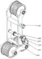
图1为本发明面向危险灾害现场环境的履带可变形机器人移动平台一种实施例的立体结构示意图;Fig. 1 is the three-dimensional structure schematic diagram of an embodiment of the crawler deformable robot mobile platform facing the dangerous disaster scene environment of the present invention;
图2为本发明面向危险灾害现场环境的履带可变形机器人移动平台一种实施例的后固定支撑架的结构示意图;Fig. 2 is a structural schematic diagram of the rear fixed support frame of an embodiment of the crawler deformable robot mobile platform facing the dangerous disaster site environment of the present invention;
图3为本发明面向危险灾害现场环境的履带可变形机器人移动平台一种实施例的前固定支撑架的结构示意图;Fig. 3 is a structural schematic diagram of the front fixed support frame of an embodiment of the crawler deformable robot mobile platform facing the dangerous disaster site environment of the present invention;
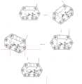
图4为本发明面向危险灾害现场环境的履带可变形机器人移动平台一种实施例的被动自适应机构的立体结构示意图;Fig. 4 is a three-dimensional structural schematic diagram of a passive adaptive mechanism of an embodiment of a crawler deformable robot mobile platform oriented to a dangerous disaster site environment;
图5为本发明面向危险灾害现场环境的履带可变形机器人移动平台一种实施例的第三齿轮1313的安装结构示意图;Fig. 5 is a schematic diagram of the installation structure of the
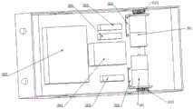
图6为本发明面向危险灾害现场环境的履带可变形机器人移动平台一种实施例的机器人本体内部结构示意图;Fig. 6 is a schematic diagram of the internal structure of the robot body of an embodiment of the crawler deformable robot mobile platform facing the dangerous disaster site environment of the present invention;
图7为本发明面向危险灾害现场环境的履带可变形机器人移动平台在斜坡上的运动姿态示意图;7 is a schematic diagram of the movement posture of the mobile platform of the crawler deformable robot facing the dangerous disaster scene environment on the slope of the present invention;
图8为本发明面向危险灾害现场环境的履带可变形机器人移动平台在越过凸台时的运动过程示意图;Fig. 8 is a schematic diagram of the movement process of the crawler deformable robot mobile platform facing the dangerous disaster scene environment when it crosses the boss;
图9为本发明面向危险灾害现场环境的履带可变形机器人移动平台在越过壕沟时的运动过程示意图;Fig. 9 is a schematic diagram of the movement process of the crawler deformable robot mobile platform facing the dangerous disaster scene environment when crossing the trench;
图中,1-被动自适应履带模块,2-信息采集模块,3-机器人本体,201-双向语音部件,202-测距传感器,203-生命体征探测部件和视频探测部件,204-有毒气体探测部件,205-救援物资部件,11-固定支撑架,12-履带驱动轮,13-被动自适应机构,14-履带,15-履带从动轮,16-履带承重轮,In the figure, 1-passive adaptive crawler module, 2-information collection module, 3-robot body, 201-two-way voice component, 202-ranging sensor, 203-vital sign detection component and video detection component, 204-toxic gas detection Components, 205-rescue material parts, 11-fixed support frame, 12-track drive wheel, 13-passive adaptive mechanism, 14-track, 15-track driven wheel, 16-track load-bearing wheel,
1101-机器人本体连接轴三,1102-第一齿轮,1103-第三齿轮,1104-驱动轮轴,1105-第四齿轮,1106-后下限位轴,1107-前上限位轴,1108-机器人本体连接轴一,1109-固定支撑架连接轴;1101-robot body connecting shaft three, 1102-first gear, 1103-third gear, 1104-drive axle, 1105-fourth gear, 1106-rear lower limit shaft, 1107-front upper limit shaft, 1108-robot body connection Axis 1, 1109-fixed support frame connecting shaft;
1301-滑槽轴,1302-从动轮支架,1303-上弹簧轴,1304-套筒,1305-传动带,1306-机器人本体连接轴二,1307-驱动轮支架与从动轮支架连接轴,1308-下弹簧轴,1309-弹簧,1310-驱动轮支架,1311-驱动轮支架与滑块机构相连轴,1312-滑槽,1313-第二齿轮,1301-chute shaft, 1302-driven wheel bracket, 1303-upper spring shaft, 1304-sleeve, 1305-drive belt, 1306-robot body connecting shaft 2, 1307-driving wheel bracket and driven wheel bracket connecting shaft, 1308-bottom Spring shaft, 1309-spring, 1310-drive wheel support, 1311-drive wheel support and slider mechanism connected shaft, 1312-chute, 1313-second gear,
301-电机,302-电机安装支架,303-电机驱动器,304-工控机,305-电源、数据采集卡306。301-motor, 302-motor mounting bracket, 303-motor driver, 304-industrial computer, 305-power supply,
具体实施方式Detailed ways
下面结合实施例及附图进一步解释本发明,但并不以此作为对本申请保护范围的限定。The present invention will be further explained below in conjunction with the embodiments and accompanying drawings, but this should not be used as a limitation to the protection scope of the present application.
本发明面向危险灾害现场环境的履带可变形机器人移动平台(简称平台或移动平台,参见图1-6)包括机器人本体3、两个左右对称布置在机器人本体上的被动自适应履带模块1及安装在机器人本体上的信息采集模块2;The crawler deformable robot mobile platform (abbreviated as platform or mobile platform, see Fig. 1-6) oriented to the dangerous and disaster site environment of the present invention includes a robot body 3, two passive self-adaptive crawler modules 1 arranged symmetrically on the robot body and installation Information collection module 2 on the robot body;
所述信息采集模块2包括生命体征探测部件和视频探测部件203、双向语音部件201、有毒气体探测部件204、救援物资部件205及测距传感器202;The information collection module 2 includes a vital sign detection component and a
每个被动自适应履带模块1均包括履带14、被动自适应机构13、四个固定支撑架11、三个履带从动轮15、四个履带承重轮16、一个履带驱动轮12,固定支撑架均为倒Y形框架,两两固定支撑架为一组,一组的两个固定支撑架通过相应的连接轴左右对称连接在一起,在每组固定支撑架的下部Y字形两个端部位置均通过相应的连接轴分别固定两个履带承重轮16,在每组固定支撑架的上部通过相应的连接轴固定有一个履带从动轮15;位于前方的两个固定支撑架为前固定支撑架,位于后方的两个固定支撑架为后固定支撑架;所述被动自适应机构13的两端通过相应轴分别连接有一个履带从动轮和一个履带驱动轮12,被动自适应机构13横跨在两个前固定支撑架和两个后固定支撑架之间,三个履带从动轮15、四个履带承重轮16、一个履带驱动轮12外表面共同支撑履带14;Each passive self-adaptive track module 1 comprises
所述被动自适应机构13包括从动轮支架1302、上弹簧轴1303、套筒1304、传动带1305、机器人本体连接轴二1306、下弹簧轴1308、弹簧1309、驱动轮支架1310和滑块机构;The passive
所述从动轮支架1302由两个结构相同的L形框架构成,L形框架的折角位置通过机器人本体连接轴二1306与机器人本体3相连,机器人本体连接轴二1306通过相应轴承安装在从动轮支架和机器人本体的相应安装孔上,机器人本体连接轴二1306一端伸入机器人本体内,并通过定位法兰固定;位于两个L形框架之间的机器人本体连接轴二1306上设有套筒1304;L形框架的长边顶点上安装履带从动轮15,在机器人本体连接轴二1306和履带从动轮15之间的L形框架上安装上弹簧轴1303;L形框架的短边下端与驱动轮支架1310的中部连接;The driven
所述驱动轮支架1310由两个结构相同的弯折杆构成,每个弯折杆的弯折角度为钝角,弯折杆的长边一端的内侧连接滑块机构,长边的中部连接L形框架的短边下端,在滑块机构和L形框架的短边下端之间的弯折杆上安装有下弹簧轴1308;The
上弹簧轴和下弹簧轴均在轴的中部加工有用于安装弹簧的凹槽,所述弹簧1309一端固定在上弹簧轴上,一端固定在下弹簧轴上,即即弹簧的头部和尾部直接卡在上下弹簧轴上即可完成安装,弹簧起到柔性连接L型框架和弯折杆的作用;Both the upper spring shaft and the lower spring shaft are processed with grooves for installing springs in the middle of the shaft. One end of the
弯折杆的短边一端通过相应的履带轮连接轴安装一个履带驱动轮12,在该履带轮连接轴上通过轴承安装有第二齿轮1313;One end of the short side of the bending rod is installed with a
所述滑块机构包括滑槽轴1301、驱动轮支架与滑块机构相连轴1311及两个滑槽1312,所述驱动轮支架与滑块机构相连轴1311的两端通过相应轴承固定在两个弯折杆之间,两个滑槽1312的一端套在驱动轮支架与滑块机构相连轴1311上,另一端通过相应轴承与滑槽轴1301连接;所述滑槽轴一端与外侧的滑槽固连,另一端伸出内侧的滑槽与机器人本体的箱体板连接固定;驱动轮支架与滑块机构相连轴1311能在滑槽内左右移动,滑槽能绕着滑槽轴相对机器人本体转动,驱动轮支架与滑块机构相连轴1311起滑块的作用;The slider mechanism includes a
在位于弯折杆弯折位置的上方的后固定支撑架上安装驱动轮轴1104,所述驱动轮轴1104一端与外侧的后固定支撑架固连,另一端依次穿过第一齿轮1102、内侧的后固定支撑架、机器人本体的箱体板连接第三齿轮1103,所述第三齿轮与机器人本体内的电机输出轴上的第四齿轮1105相啮合;所述第一齿轮1102通过传动带1305连接第二齿轮1313;所述驱动轮轴1104的高度小于履带驱动轮12的高度。The
在前固定支撑架上,且位于L形框架的上方的连接轴为前上限位轴1107;在后固定支撑架上,且位于弯折杆下方的连接轴为后下限位轴1106;前固定支撑架和后固定支撑架上的连接轴内侧与机器人本体连接固定。On the front fixed support frame, the connecting shaft positioned above the L-shaped frame is the front
所述机器人本体3包括箱体板、电源305、数据采集卡306、两个电机301、两个电机驱动器303和工控机304,电机301、数据采集卡306、电机驱动器303和工控机304均安装在箱体板内,两个电机驱动器分别通过一个电机驱动一侧的被动自适应履带模块,所述工控机与电机驱动器连接,同时通过数据采集卡与信息采集模块连接,电源给电机、电机驱动器、工控机以及信息采集模块供电,信息采集模块收集的数据经过数据采集卡,然后发送到工控机中。工控机然后对数据进行处理,进而驱动电机执行相应的命令。Described robot body 3 comprises box body plate,
本发明中所述履带从动轮15、履带承重轮16及履带驱动轮12均采用两个相同轮子对接构成,以增大轮子与履带的接触面积,当采用两个相同轮子组成一个履带驱动轮时,所述第二齿轮通过轴承安装在这两个相同轮子之间,保证被动自适应机构整体的受力均衡。The track driven
本发明面向危险灾害现场环境的履带可变形机器人移动平台,具有两种运动模式:在正常平整的路面上移动;在抽象为凸台、斜坡、壕沟等非结构化灾害现场环境中移动,这里的所能越过的凸台的高度不能超过平台变形后重心的高度;具体运动过程是:The crawler deformable robot mobile platform of the present invention is oriented to the scene environment of dangerous disasters. It has two motion modes: moving on a normal and flat road surface; The height of the boss that can be crossed cannot exceed the height of the center of gravity of the platform after deformation; the specific movement process is:
1)在正常平整、斜坡的路面上移动(参见图7):1) Moving on a normal flat and sloped road (see Figure 7):
电机输出动力,经过第四齿轮1105和第三齿轮1103带动驱动轮轴1104,驱动轮轴1104带动第一齿轮1102,第一齿轮1102通过传动带1305把动力传送第二齿轮1313,第二齿轮1313与履带驱动轮12安装在同一根轴上,继而把动力传输到履带驱动轮12,履带驱动轮12通过履带14将电机输出的动力,传递给履带承重轮16和履带从动轮15,完成整个被动自适应履带模块的驱动。实现整个机器人平稳移动。信息采集模块收集的数据经过数据采集卡,然后发送到工控机中,工控机然后对数据进行处理。The output power of the motor drives the
2)在抽象为凸台、壕沟等非结构化灾害现场环境中移动(参见图8和图9):2) Moving in the unstructured disaster site environment abstracted as bosses and trenches (see Figure 8 and Figure 9):
电机输出动力,经过第四齿轮1105和第三齿轮1103带动驱动轮轴1104,驱动轮轴1104带动第一齿轮1102,第一齿轮1102通过传动带1305把动力传送第二齿轮1313,第二齿轮1313与履带驱动轮12安装在同一根轴上,继而把动力传输到履带驱动轮12,履带驱动轮12通过履带14将电机输出的动力,传递给履带承重轮16和履带从动轮15,完成整个被动自适应履带模块的驱动。The output power of the motor drives the
当转动的履带14接触到障碍物时,从动轮支架1302将绕机器人本体连接轴二1306顺时针转动,同时也将通过驱动轮支架与从动轮支架连接轴1307带动驱动轮支架1310顺时针转动,驱动轮支架1310转动将带动驱动轮支架与滑块机构相连轴1311沿着滑槽滑动,滑槽1312绕滑槽轴1301转动。When the
由于弹簧1309通过上弹簧轴1303和下弹簧轴1308安装,由于弹簧1309弹力和驱动轮支架与从动轮支架连接轴1307的力的合力作用,所以驱动轮支架1310一定绕着顺时针转动,并且由于弹簧1309的存在,在机器人越障结束后,从动轮支架1302将由于重力和弹簧1309弹力的作用恢复原来的位置,并且带动驱动轮支架1310恢复原来的位置。Because the
当驱动轮支架1310绕着顺时针转动,滑槽1312相当于受到一个向上的作用力绕滑槽轴1301逆时针转动,并且驱动轮支架与滑块机构相连轴1311沿着滑槽滑动。When the
对驱动轮支架1310和从动轮支架1302极限位置的限制:由于驱动轮支架1310绕驱动轮支架与从动轮支架连接轴1307顺时针转动,所以对驱动轮支架1310设置安全的下极限位置,当驱动轮支架1310接触到后下限位轴1106时的位置为驱动轮支架1310下极限位置。由于从动轮支架1302将绕机器人本体连接轴二1306顺时针转动,所以对从动轮支架1302设置上极限位置,当从动轮支架1302接触到前上限位轴1107时的位置为从动轮支架1302的上极限位置。Restrictions on the extreme positions of the
当机器人进入灾害环境时,生命体征探测部件和视频探测部件203给远程操控机器人的工作人员,提供灾害现场的视频场景和对视频无法监控到的废墟进行生命体征探测,进而发现有无被困人员,从而采取相应的行动。双向语音部件201是在机器人发现被困人员时,用于救援人员和被困人员进行双向语音沟通,方便救援人员更加清楚的了解现场环境,从而做出准确的救援决策。有毒气体探测部件204用于探测灾害现场的有毒气体成分和浓度,方便救援人员进入灾害现场作业时,采取相应的保护措施。救援物资部件205是机器人携带的救援物资,方便有能力自救的被困人员及时地进行自救,从而减轻救援人员的救援工作压力。测距传感器202是为了给救援人员一个参数化的灾害现场环境,从而更好的对机器人进行路径规划。When the robot enters a disaster environment, the vital sign detection component and the
实施例1Example 1
本实施例面向危险灾害现场环境的履带可变形机器人移动平台包括机器人本体3、两个左右对称布置在机器人本体上的被动自适应履带模块1及安装在机器人本体上的信息采集模块2;In this embodiment, the crawler deformable robot mobile platform for dangerous disaster site environment includes a robot body 3, two passive self-adaptive crawler modules 1 arranged symmetrically on the robot body and an information collection module 2 installed on the robot body;
所述信息采集模块2包括生命体征探测部件和视频探测部件203、双向语音部件201、有毒气体探测部件204、救援物资部件205及测距传感器202;The information collection module 2 includes a vital sign detection component and a
每个被动自适应履带模块1均包括履带14、被动自适应机构13、四个固定支撑架11、三个履带从动轮15、四个履带承重轮16、一个履带驱动轮12,固定支撑架均为倒Y形框架,两两固定支撑架为一组,一组的两个固定支撑架通过相应的连接轴左右对称连接在一起,在每组固定支撑架的下部Y字形两个端部位置均通过相应的连接轴分别固定两个履带承重轮16,在每组固定支撑架的上部通过相应的连接轴固定有一个履带从动轮15;位于前方的两个固定支撑架为前固定支撑架,位于后方的两个固定支撑架为后固定支撑架;所述被动自适应机构13的两端通过相应轴分别连接有一个履带从动轮和一个履带驱动轮12,被动自适应机构13横跨在两个前固定支撑架和两个后固定支撑架之间,三个履带从动轮15、四个履带承重轮16、一个履带驱动轮12外表面共同支撑履带14;Each passive self-adaptive track module 1 comprises
两个前固定支撑架和两个固定后支撑架左右对称布置。Two front fixed support frames and two fixed rear support frames are symmetrically arranged left and right.
前固定支撑架通过前上限位轴1107、机器人本体连接轴一1108与机器人本体连接;所述前固定支撑架的倒Y形框架从上到下依次设有履带从动轮安装孔,前上限位轴安装孔,机器人本体连接轴一安装孔,固定支撑架连接轴安装孔以及两个履带承重轮安装孔。The front fixed support frame is connected with the robot body by the front
前固定支撑架上的履带从动轮和履带承重轮通过相应的轴承和相应的轴安装在所述的履带从动轮轴安装孔和履带承重轮安装孔上。前上限位轴1107通过相应的前上限位轴安装孔一端安装在前固定支撑架上,一端伸入机器人本体内,机器人本体内装有定位法兰,通过定位法兰进行固定。机器人本体连接轴一1108通过相应的机器人本体连接轴一安装孔一端安装在前固定支撑架上,一端伸入机器人本体内,在机器人本体内通过相应的定位法兰固定。固定支撑架连接轴1109安装在相应的固定支撑架连接轴安装孔上将两个前固定支撑架连接起来。The track driven wheel and the track load wheel on the front fixed support frame are installed on the track driven wheel shaft mounting hole and the track load wheel mounting hole through corresponding bearings and corresponding shafts. Front
后固定支撑架通过驱动轮轴1104、机器人本体连接轴三1101与机器人本体相连。所述后固定支撑架的倒Y形框架从上到下依次设有履带从动轮安装孔,机器人本体连接轴三安装孔,驱动轮轴安装孔,后下限位轴安装孔以及两个履带承重轮安装孔。The rear fixed support frame is connected with the robot body through the
后固定支撑架上的履带从动轮和履带承重轮通过相应的轴承和相应的轴安装在所述的履带从动轮轴安装孔和履带承重轮安装孔上。机器人本体连接轴三1101通过机器人本体连接轴三安装孔一端安装在后固定支撑架上,一端伸入机器人本体内,机器人本体内相应位置装有定位法兰。驱动轮轴1104通过相应的轴承安装在相应的驱动轮轴安装孔上。第一齿轮1102通过相应的轴承安装在所述的驱动轮轴1104上。后下限位轴1106通过安装在相应的后下限位轴安装孔上将后固定支撑架连接起来,并且限定驱动轮支架1310的下极限位置。Track driven wheels and track load wheels on the rear fixed support frame are installed on the track driven wheel shaft mounting holes and track load wheel mounting holes through corresponding bearings and corresponding shafts. The robot body connecting shaft three 1101 is installed on the rear fixed support frame through the robot body connecting shaft three mounting hole one end, and one end stretches into the robot body, and the corresponding position in the robot body is equipped with a positioning flange. The
所述被动自适应机构13包括从动轮支架1302、上弹簧轴1303、套筒1304、传动带1305、机器人本体连接轴二1306、下弹簧轴1308、弹簧1309、驱动轮支架1310和滑块机构;The passive
所述驱动轮支架1310为两个结构相同的弯折杆,每个弯折杆的弯折角度为120°,从左到右依次有驱动轮支架与滑块机构相连轴安装孔,下弹簧轴安装孔,驱动轮支架与从动轮支架连接轴安装孔、履带驱动轮安装孔。The
通过驱动轮支架与滑块机构相连轴安装孔安装相应的轴承及驱动轮支架与滑块机构相连轴1311,将驱动轮支架1310与滑块机构相连,通过下弹簧轴安装孔安装下弹簧轴1308,并在下弹簧轴1308上安装弹簧的尾部。通过驱动轮支架与从动轮支架连接轴安装孔安装驱动轮支架与从动轮支架连接轴1307和相应的轴承,将驱动轮支架1310与从动轮支架1302相连接。通过履带驱动轮安装孔安装相应的轴承和履带驱动轮、履带驱动轮轴,并在履带驱动轮轴上安装履带驱动轮和第二齿轮1313,实现机器人的传动。Install the corresponding bearing and the
所述从动轮支架1302为L形框架通过机器人本体连接轴二1306与机器人本体相连。在从动轮支架1302的L形框架的长边从左到右依次设有履带从动轮安装孔、上弹簧轴安装孔。L形框架的短边处从上往下依次设有机器人本体连接轴二安装孔、驱动轮支架与从动轮支架连接轴安装孔。驱动轮支架与从动轮支架连接轴安装孔位于弯折杆的弯折位置的左侧。The driven
通过履带从动轮安装孔安装相应的轴承、履带从动轮15、履带从动轮轴,通过上弹簧轴安装孔安装上弹簧轴1303,并在上弹簧轴1303上安装弹簧的头部。所述机器人本体连接轴二1306通过轴承安装在从动轮支撑架1302和机器人本体的相应安装孔上,机器人本体连接轴二1306一端伸入机器人本体内,机器人本体内装有定位法兰,另一端,将两个从动轮支架1302相连接。所述驱动轮支架与从动轮支架连接轴1307通过安装于驱动轮支架与从动轮支架连接轴安装孔相应位置上的轴承将驱动轮支架和从动轮支架相连。Corresponding bearing, track driven
所述滑块机构包括滑槽轴1301、驱动轮支架与滑块机构相连轴1311及两个滑槽1312。所述滑槽1312通过滑槽轴1301与机器人本体的箱体板连接,驱动轮支架与滑块机构相连轴1311为滑块,其通过轴承安装在两个驱动轮支架的相应的驱动轮支架与滑块机构相连轴安装孔上,两个滑槽1312的一端套在驱动轮支架与滑块机构相连轴1311上,另一端通过相应轴承与滑槽轴1301连接;所述滑槽轴1301一端与外侧的滑槽固连,另一端伸出内侧的滑槽与机器人本体的箱体板连接固定;驱动轮支架与滑块机构相连轴1311能在滑槽内左右移动,滑槽能绕着滑槽轴相对机器人本体转动,驱动轮支架与滑块机构相连轴1311起滑块的作用;The slider mechanism includes a
在位于弯折杆弯折位置的上方的后固定支撑架上安装驱动轮轴1104,所述驱动轮轴1104一端与外侧的后固定支撑架固连,另一端依次穿过第一齿轮1102、内侧的后固定支撑架、机器人本体的箱体板连接第三齿轮1103,所述第三齿轮与机器人本体内的电机输出轴上的第四齿轮1105相啮合;所述第一齿轮1102通过传动带1305连接第二齿轮1313;所述驱动轮轴1104的高度小于履带驱动轮12的高度。The
在前固定支撑架上,且位于L形框架的上方的连接轴为前上限位轴1107;在后固定支撑架上,且位于弯折杆下方的连接轴为后下限位轴1106;前固定支撑架和后固定支撑架上的连接轴内侧与机器人本体连接固定。On the front fixed support frame, the connecting shaft positioned above the L-shaped frame is the front
本实施例中生命体征探测部件和视频探测部件203采用讯时红外线生命探测仪和中维模组H.265解码网络摄像头的组合,有毒气体探测部件204采用四合一气体检测仪,测距传感器202采用深达威激光测距传感器,救援物资部件205里面放置水、氧气包、营养液等物品。In the present embodiment, the vital sign detection component and the
本发明未述及之处适用于现有技术。What is not mentioned in the present invention is applicable to the prior art.
Claims (5)
Translated fromChinesePriority Applications (1)
| Application Number | Priority Date | Filing Date | Title |
|---|---|---|---|
| CN201810612270.6ACN108673469B (en) | 2018-06-14 | 2018-06-14 | Caterpillar band deformable robot moving platform for dangerous disaster site environment |
Applications Claiming Priority (1)
| Application Number | Priority Date | Filing Date | Title |
|---|---|---|---|
| CN201810612270.6ACN108673469B (en) | 2018-06-14 | 2018-06-14 | Caterpillar band deformable robot moving platform for dangerous disaster site environment |
Publications (2)
| Publication Number | Publication Date |
|---|---|
| CN108673469A CN108673469A (en) | 2018-10-19 |
| CN108673469Btrue CN108673469B (en) | 2023-04-25 |
Family
ID=63810863
Family Applications (1)
| Application Number | Title | Priority Date | Filing Date |
|---|---|---|---|
| CN201810612270.6AExpired - Fee RelatedCN108673469B (en) | 2018-06-14 | 2018-06-14 | Caterpillar band deformable robot moving platform for dangerous disaster site environment |
Country Status (1)
| Country | Link |
|---|---|
| CN (1) | CN108673469B (en) |
Families Citing this family (7)
| Publication number | Priority date | Publication date | Assignee | Title |
|---|---|---|---|---|
| CN109305238B (en)* | 2018-12-03 | 2023-09-29 | 河北工业大学 | Passive self-adaptive tracked robot moving platform |
| CN109398517A (en)* | 2018-12-29 | 2019-03-01 | 合肥多加农业科技有限公司 | A kind of leg structure and the agricultural machinery using this leg structure |
| CN110171495A (en)* | 2019-04-19 | 2019-08-27 | 北京交通大学 | A kind of deformable link-type crawler belt obstacle detouring system |
| WO2021076579A1 (en) | 2019-10-18 | 2021-04-22 | Off-World, Inc. | Industrial robotic platforms |
| CN110977922B (en)* | 2019-12-11 | 2020-08-25 | 东北石油大学 | An adaptive crawler device attached to the outer wall of the pipeline |
| CN110937038A (en)* | 2019-12-17 | 2020-03-31 | 三一汽车制造有限公司 | Walking devices and unmanned vehicles |
| CN113548119B (en)* | 2021-09-02 | 2022-10-18 | 厦门理工学院 | Variable multipurpose miniature mobile platform |
Citations (6)
| Publication number | Priority date | Publication date | Assignee | Title |
|---|---|---|---|---|
| FR2638698A1 (en)* | 1988-11-04 | 1990-05-11 | Cybernetix | Articulated roller-suspension device for tracked vehicles |
| CN2664857Y (en)* | 2003-12-25 | 2004-12-22 | 章永泰 | Underwater desilting and reaping device for ecological harness |
| JP2007302083A (en)* | 2006-05-10 | 2007-11-22 | Kikuichi:Kk | Traveling device of endless track |
| CN103273977A (en)* | 2013-05-14 | 2013-09-04 | 河北工业大学 | Passive self-adaption deformable continuous track type mobile robot platform |
| CN105460090A (en)* | 2015-12-16 | 2016-04-06 | 河北工业大学 | Track deformable robot mobile platform |
| CN107140153A (en)* | 2017-05-17 | 2017-09-08 | 湖南大学 | Adaptive strain born of the same parents' crawler belt traveling mechanism |
- 2018
- 2018-06-14CNCN201810612270.6Apatent/CN108673469B/ennot_activeExpired - Fee Related
Patent Citations (6)
| Publication number | Priority date | Publication date | Assignee | Title |
|---|---|---|---|---|
| FR2638698A1 (en)* | 1988-11-04 | 1990-05-11 | Cybernetix | Articulated roller-suspension device for tracked vehicles |
| CN2664857Y (en)* | 2003-12-25 | 2004-12-22 | 章永泰 | Underwater desilting and reaping device for ecological harness |
| JP2007302083A (en)* | 2006-05-10 | 2007-11-22 | Kikuichi:Kk | Traveling device of endless track |
| CN103273977A (en)* | 2013-05-14 | 2013-09-04 | 河北工业大学 | Passive self-adaption deformable continuous track type mobile robot platform |
| CN105460090A (en)* | 2015-12-16 | 2016-04-06 | 河北工业大学 | Track deformable robot mobile platform |
| CN107140153A (en)* | 2017-05-17 | 2017-09-08 | 湖南大学 | Adaptive strain born of the same parents' crawler belt traveling mechanism |
Non-Patent Citations (1)
| Title |
|---|
| 张明路 ; 李敏 ; 田颖 ; 吕晓玲 ; .单履带被动自适应机器人设计与运动学分析.华中科技大学学报(自然科学版).2018,(第03期),第69-74页.* |
Also Published As
| Publication number | Publication date |
|---|---|
| CN108673469A (en) | 2018-10-19 |
Similar Documents
| Publication | Publication Date | Title |
|---|---|---|
| CN108673469B (en) | Caterpillar band deformable robot moving platform for dangerous disaster site environment | |
| CN103287523B (en) | The composite deformation mobile robot that a kind of elastic foot is combined with wheel type motion mechanism | |
| CN108163080B (en) | Electrically driven quadruped robot capable of adapting to high load capacity of complex rugged terrain | |
| CN103273977B (en) | Passive self-adaption deformable continuous track type mobile robot platform | |
| CN105667622B (en) | A six-wheeled mobile robot with a three-segment body | |
| CN103879467B (en) | The differential mobile robot platform of a kind of passive self adaptation crawler belt deformable rocking bar | |
| CN106184434B (en) | Wheel carries out transformation mobile chassis and the fire-fighting sniffing robot with it | |
| CN110126562B (en) | An air-ground integrated electric parallel wheel-foot drive mechanism | |
| CN203237312U (en) | Combination shape-shifting mobile robot with elastic feet and wheel-type movement mechanism combined | |
| CN213473334U (en) | Emergency rescue unmanned vehicle | |
| CN105151153A (en) | Wheel-foot hybrid mode hexapod robot moving platform | |
| CN105438291A (en) | Robot moving platform with deformable tracks | |
| CN115583298B (en) | A variable configuration wheeled robot structure | |
| CN107140053B (en) | Wheel-leg type mobile robot based on spherical parallel mechanism | |
| CN105774899A (en) | Mobile robot used for agriculture and forestry nursery operation | |
| CN202320576U (en) | Stair climbing robot | |
| CN218055418U (en) | Wheel leg switching robot | |
| CN108297965A (en) | A kind of quadruped robot | |
| CN102114879B (en) | Biped walking four-bar mechanism | |
| CN102642572B (en) | Duplex triangle connecting frame variable configuration crawler-type obstacle-crossing mechanism | |
| CN208181238U (en) | A kind of quadruped robot | |
| CN215245183U (en) | Caterpillar chassis posture adjusting device | |
| CN2841272Y (en) | Composite moving mechanism of autonomous obstacle-surmounting robot | |
| CN115610547A (en) | A sensitive omnidirectional mobile wheel-legged robot with multi-modal active motion switching | |
| CN212096375U (en) | Unicycle |
Legal Events
| Date | Code | Title | Description |
|---|---|---|---|
| PB01 | Publication | ||
| PB01 | Publication | ||
| SE01 | Entry into force of request for substantive examination | ||
| SE01 | Entry into force of request for substantive examination | ||
| GR01 | Patent grant | ||
| GR01 | Patent grant | ||
| CF01 | Termination of patent right due to non-payment of annual fee | ||
| CF01 | Termination of patent right due to non-payment of annual fee | Granted publication date:20230425 |