CN108666742B - Multi-frequency antenna and communication equipment - Google Patents
Multi-frequency antenna and communication equipmentDownload PDFInfo
- Publication number
- CN108666742B CN108666742BCN201710210258.8ACN201710210258ACN108666742BCN 108666742 BCN108666742 BCN 108666742BCN 201710210258 ACN201710210258 ACN 201710210258ACN 108666742 BCN108666742 BCN 108666742B
- Authority
- CN
- China
- Prior art keywords
- radiation unit
- radiation
- unit
- frequency antenna
- wire
- Prior art date
- Legal status (The legal status is an assumption and is not a legal conclusion. Google has not performed a legal analysis and makes no representation as to the accuracy of the status listed.)
- Active
Links
Images


Classifications
- H—ELECTRICITY
- H01—ELECTRIC ELEMENTS
- H01Q—ANTENNAS, i.e. RADIO AERIALS
- H01Q1/00—Details of, or arrangements associated with, antennas
- H01Q1/36—Structural form of radiating elements, e.g. cone, spiral, umbrella; Particular materials used therewith
- H—ELECTRICITY
- H01—ELECTRIC ELEMENTS
- H01Q—ANTENNAS, i.e. RADIO AERIALS
- H01Q1/00—Details of, or arrangements associated with, antennas
- H01Q1/50—Structural association of antennas with earthing switches, lead-in devices or lightning protectors
- H—ELECTRICITY
- H01—ELECTRIC ELEMENTS
- H01Q—ANTENNAS, i.e. RADIO AERIALS
- H01Q19/00—Combinations of primary active antenna elements and units with secondary devices, e.g. with quasi-optical devices, for giving the antenna a desired directional characteristic
- H01Q19/10—Combinations of primary active antenna elements and units with secondary devices, e.g. with quasi-optical devices, for giving the antenna a desired directional characteristic using reflecting surfaces
- H01Q19/104—Combinations of primary active antenna elements and units with secondary devices, e.g. with quasi-optical devices, for giving the antenna a desired directional characteristic using reflecting surfaces using a substantially flat reflector for deflecting the radiated beam, e.g. periscopic antennas
- H—ELECTRICITY
- H01—ELECTRIC ELEMENTS
- H01Q—ANTENNAS, i.e. RADIO AERIALS
- H01Q21/00—Antenna arrays or systems
- H—ELECTRICITY
- H01—ELECTRIC ELEMENTS
- H01Q—ANTENNAS, i.e. RADIO AERIALS
- H01Q5/00—Arrangements for simultaneous operation of antennas on two or more different wavebands, e.g. dual-band or multi-band arrangements
- H01Q5/20—Arrangements for simultaneous operation of antennas on two or more different wavebands, e.g. dual-band or multi-band arrangements characterised by the operating wavebands
Landscapes
- Aerials With Secondary Devices (AREA)
- Variable-Direction Aerials And Aerial Arrays (AREA)
Abstract
Translated fromChinese
Description
Translated fromChinese技术领域technical field
本发明涉及通信技术领域,尤其涉及多频天线及通信设备。The present invention relates to the field of communication technologies, and in particular, to a multi-frequency antenna and a communication device.
背景技术Background technique
多频天线包括支持不同工作频段的多个独立的天线,因此,多频天线尺寸大。The multi-frequency antenna includes multiple independent antennas supporting different operating frequency bands, and therefore, the multi-frequency antenna is large in size.
发明内容SUMMARY OF THE INVENTION
本申请的目的在于提供一种多频天线,以在缩小多频天线的尺寸的同时维持多频天线的性能。The purpose of the present application is to provide a multi-frequency antenna, so as to reduce the size of the multi-frequency antenna while maintaining the performance of the multi-frequency antenna.
本申请还提供一种通信设备。The present application also provides a communication device.
第一方面,本申请提供一种多频天线,所述多频天线包括:反射板和位于所述反射板上方的辐射组件;其中,In a first aspect, the present application provides a multi-frequency antenna, the multi-frequency antenna includes: a reflector and a radiation component located above the reflector; wherein,
所述辐射组件包括第一辐射单元及第二辐射单元,所述第一辐射单元及所述第二辐射单元的工作频段不同;The radiation component includes a first radiation unit and a second radiation unit, and the working frequency bands of the first radiation unit and the second radiation unit are different;
所述第一辐射单元的尺寸大于所述第二辐射单元的尺寸,所述第二辐射单元设置于所述第一辐射单元的上方,所述第二辐射单元在所述第一辐射单元上的投影完全在所述第一辐射单元之内。The size of the first radiation unit is larger than the size of the second radiation unit, the second radiation unit is arranged above the first radiation unit, and the second radiation unit is on the first radiation unit. The projection is completely within the first radiating element.
由于所述第一辐射单元和所述第二辐射单元重叠,反射板上方的第一及第二辐射单元在反射板上所占的区域的面积小于传统的多频天线中辐射单元在反射板上所占的面积。进而本申请中的反射板的尺寸也可以缩小,从而缩小多频天线的尺寸。另外,第二辐射单元位于第一辐射单元的上方,第二辐射单元在第一辐射单元的投影完全在所述第一辐射单元之内。即所述第二辐射单元在第一辐射单元的投影完全在第一辐射单元的内部区域内。由于辐射单元的内部区域几乎没有辐射能量,所述第二辐射单元与所述第一辐射单元之间几乎没有干扰,各辐射单元的性能得以维持。Since the first radiating element and the second radiating element overlap, the area occupied by the first and second radiating elements above the reflective plate on the reflective plate is smaller than that of the radiating element on the reflective plate in the traditional multi-frequency antenna area occupied. Furthermore, the size of the reflector in the present application can also be reduced, thereby reducing the size of the multi-frequency antenna. In addition, the second radiation unit is located above the first radiation unit, and the projection of the second radiation unit on the first radiation unit is completely within the first radiation unit. That is, the projection of the second radiation unit on the first radiation unit is completely within the inner area of the first radiation unit. Since the inner area of the radiation unit has almost no radiation energy, there is little interference between the second radiation unit and the first radiation unit, and the performance of each radiation unit is maintained.
在第一方面的第一种可能的实现方式中,所述辐射组件还包括连接件,所述连接件连接所述第二辐射单元的馈电口和收发器件,其中,所述连接件贯穿所述第一辐射单元的内部区域及反射板。由于辐射单元的内部区域几乎没有辐射能量,所述第二辐射单元的信号与所述第一辐射单元之间几乎没有干扰。In a first possible implementation manner of the first aspect, the radiating component further includes a connecting member, the connecting member connects the feeding port of the second radiating unit and the transceiver device, wherein the connecting member penetrates through the The inner area of the first radiation unit and the reflector are described. Since the inner area of the radiation unit has almost no radiation energy, there is little interference between the signal of the second radiation unit and the first radiation unit.
结合第一方面的第一种可能的实现方式,在第一方面的第二种可能的实现方式中,所述连接件为同轴线,所述同轴线穿过所述第一辐射单元的内部区域及所述反射板,所述同轴线的一端连接所述第二辐射单元的馈电口,所述同轴线的另一端连接收发器件。With reference to the first possible implementation manner of the first aspect, in a second possible implementation manner of the first aspect, the connecting member is a coaxial line, and the coaxial line passes through the first radiation unit. In the inner area and the reflection plate, one end of the coaxial line is connected to the feed port of the second radiation unit, and the other end of the coaxial line is connected to the transceiver device.
结合第一方面的第一种可能的实现方式,在第一方面的第三种可能的实现方式中,所述连接件为线路板,所述馈电口位于所述第二辐射单元的周边,所述线路板的第一导线的一端连接所述第二辐射单元的馈电口,所述第一导线的另一端连接所述收发器件,其中,所述第一导线从所述第一辐射单元的内部区域穿过所述第一辐射单元。With reference to the first possible implementation manner of the first aspect, in a third possible implementation manner of the first aspect, the connector is a circuit board, and the feed port is located at the periphery of the second radiation unit, One end of the first wire of the circuit board is connected to the feed port of the second radiation unit, and the other end of the first wire is connected to the transceiver device, wherein the first wire is connected from the first radiation unit The inner region of the radiator passes through the first radiation unit.
所述馈电口位于所述第二辐射单元的周边,利用所述第一导线将所述馈电口连接至所述收发器件。其中,所述第一导线从所述第一辐射单元的内部区域穿过所述第一辐射单元。由于所述第一辐射单元的内部区域几乎没有辐射能量,所述第二辐射单元的信号与所述第一辐射单元之间几乎没有干扰。The power feeding port is located at the periphery of the second radiation unit, and the first wire is used to connect the power feeding port to the transceiver device. Wherein, the first wire passes through the first radiation unit from the inner area of the first radiation unit. Since the inner area of the first radiation unit has almost no radiation energy, there is almost no interference between the signal of the second radiation unit and the first radiation unit.
结合第一方面的第三种可能的实现方式,在第一方面的第四种可能的实现方式中,所述第一导线包括第一段及第二段,所述第一段平行于所述第一辐射单元,所述第二段垂直于所述第一辐射单元,所述第一段的一端连接所述第二辐射单元的馈电口,所述第一段的另一端连接所述第二段的一端,所述第二段的另一端连接所述收发器件,所述第二段从所述第一辐射单元的内部区域穿过所述第一辐射单元。With reference to the third possible implementation manner of the first aspect, in a fourth possible implementation manner of the first aspect, the first wire includes a first segment and a second segment, and the first segment is parallel to the The first radiation unit, the second segment is perpendicular to the first radiation unit, one end of the first segment is connected to the feed port of the second radiation unit, and the other end of the first segment is connected to the first radiation unit. One end of the two segments is connected to the transceiver device at the other end of the second segment, and the second segment passes through the first radiation unit from the inner area of the first radiation unit.
结合第一方面的第三或第四种可能的实现方式,在第一方面的第五种可能的实现方式中,所述第二辐射单元还包括另一馈电口,所述另一馈电口位于所述第二辐射单元的周边,且与所述馈电口分离,所述馈电口的信号与所述另一馈电口的信号正交,所述线路板上的第二导线,所述第二导线的一端与所述另一馈电口连接,所述第二导线的另一端连接所述收发器件,其中,所述第二导线从所述第一辐射单元的内部穿过所述第一辐射单元。With reference to the third or fourth possible implementation manner of the first aspect, in a fifth possible implementation manner of the first aspect, the second radiation unit further includes another feeding port, the other feeding The port is located at the periphery of the second radiating element and is separated from the feed port, the signal of the feed port is orthogonal to the signal of the other feed port, and the second wire on the circuit board, One end of the second wire is connected to the other feeding port, and the other end of the second wire is connected to the transceiver device, wherein the second wire passes through the first radiating unit from the inside the first radiation unit.
由于所述另一馈电口位于所述第二辐射单元的周边,利用所述第二导线将所述另一馈电口连接至所述收发器件。其中,所述第二导线从所述第一辐射单元的内部穿过所述第一辐射单元。由于所述第一辐射单元的内部区域几乎没有辐射能量,所述第二辐射单元的信号与所述第一辐射单元之间几乎没有干扰。Since the other feeding port is located at the periphery of the second radiation unit, the other feeding port is connected to the transceiver device by using the second wire. Wherein, the second wire passes through the first radiation unit from the inside of the first radiation unit. Since the inner area of the first radiation unit has almost no radiation energy, there is almost no interference between the signal of the second radiation unit and the first radiation unit.
结合第一方面的第五种可能的实现方式,在第一方面的第六种可能的实现方式中,所述第二导线包括第三段及第四段,所述第三段平行于所述第一辐射单元,所述第四段垂直于所述第一辐射单元,所述第三段的一端连接所述第二辐射单元的另一馈电口,所述第三段的另一端连接所述第四段的一端,所述第四段的另一端连接所述收发器件,所述第四段从所述第一辐射单元的内部区域穿过所述第一辐射单元。With reference to the fifth possible implementation manner of the first aspect, in a sixth possible implementation manner of the first aspect, the second wire includes a third segment and a fourth segment, and the third segment is parallel to the The first radiation unit, the fourth segment is perpendicular to the first radiation unit, one end of the third segment is connected to another feed port of the second radiation unit, and the other end of the third segment is connected to the One end of the fourth section is connected to the transceiver device at the other end of the fourth section, and the fourth section passes through the first radiation unit from the inner area of the first radiation unit.
结合第一方面的第五或第六种可能的实现方式,在第一方面的第七种可能的实现方式中,所述线路板包括第一子板及第二子板,所述第一子板与所述第二子板垂直,且所述第一子板与所述第二子板的相交线与所述第一辐射单元垂直,所述第一导线位于所述第一子板内,所述第二导线位于所述第二子板内。With reference to the fifth or sixth possible implementation manner of the first aspect, in a seventh possible implementation manner of the first aspect, the circuit board includes a first sub-board and a second sub-board, and the first sub-board The board is perpendicular to the second sub-board, and the intersection line of the first sub-board and the second sub-board is perpendicular to the first radiation unit, and the first wire is located in the first sub-board, The second wires are located in the second sub-board.
第二方面,本申请还提供一种通信系统,包括基站及上述第一方面的各种可能的实现方式的多频天线,所述基站用所述多频天线收发信号。In a second aspect, the present application further provides a communication system, including a base station and a multi-frequency antenna in various possible implementation manners of the above-mentioned first aspect, where the base station uses the multi-frequency antenna to send and receive signals.
附图说明Description of drawings
为了更清楚地说明本发明实施例或现有技术中的技术方案,下面将对实施例或现有技术描述中所需要使用的附图作简单地介绍,显而易见地,下面描述中的附图仅仅是本发明的一些实施例,对于本领域普通技术人员来讲,在不付出创造性劳动的前提下,还可以根据这些附图获得其他的附图。In order to explain the embodiments of the present invention or the technical solutions in the prior art more clearly, the following briefly introduces the accompanying drawings that need to be used in the description of the embodiments or the prior art. Obviously, the accompanying drawings in the following description are only These are some embodiments of the present invention. For those of ordinary skill in the art, other drawings can also be obtained according to these drawings without creative efforts.
图1是一种传统的多频天线辐射单元的平面示意图。FIG. 1 is a schematic plan view of a conventional multi-frequency antenna radiating unit.
图2是本发明第一方案第一实施例提供的一种多频天线的截面图。FIG. 2 is a cross-sectional view of a multi-frequency antenna provided by the first embodiment of the first solution of the present invention.
图3是本发明第一方案第一实施例提供的一种多频天线的平面示意图。FIG. 3 is a schematic plan view of a multi-frequency antenna provided by the first embodiment of the first solution of the present invention.
图4是本发明第一方案第二实施例提供的一种多频天线的截面图。FIG. 4 is a cross-sectional view of a multi-frequency antenna according to the second embodiment of the first solution of the present invention.
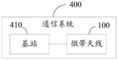
图5是本发明第二方案实施例提供的一种通信系统的框图。FIG. 5 is a block diagram of a communication system according to an embodiment of the second solution of the present invention.
具体实施方式Detailed ways
阵列天线是多个辐射单元按一定规律排列组成的天线。多频阵列天线是由支持不同工作频段的多个阵列天线共同组成的一个天线集合。多频阵列天线的尺寸通常是由反射板的大小决定的,而反射板的大小又是由该多频阵列天线中所有辐射单元在反射板上所占的区域的大小决定的。如图1所示,其为一种传统的多频阵列天线的结构示意图,该多频阵列天线包括空气基板(空气基板是由空气层构成的一种介质基板,介电常数为1)、反射板101、工作频段为2.4吉赫兹(英文:gigahertz)频段的微带天线102和工作频段为5GHz频段的微带天线103。这两种微带天线分别包括各自的辐射单元及各自的馈电网络,其中,馈电网络与辐射单元之间的连接点为馈电口。反射板101上的多个辐射单元可以通过绝缘支架架在反射板101上方,这多个辐射单元和反射板101之间为空气基板。微带天线102的辐射单元以及微带天线103的辐射单元在反射板101上均单独分离排布。由图1可以看出,微带天线102的辐射单元以及微带天线103的辐射单元在反射板101上占用了较大的区域,这致使反射板101的尺寸较大,因而多频阵列天线的尺寸较大。其中,微带天线(英文:microstripantenna)是在介质基板一侧贴加辐射单元,另一侧设置反射板而形成的天线。反射板为导体接地板(英文:ground plane)。介质基板使辐射单元和反射板之间开路。辐射单元和反射板之间的开路产生电磁波。辐射单元为微带天线的基本结构单元,它能有效地辐射或接收电磁波。工作频段为微带天线工作的频率范围。馈电网络为多个辐射单元的天线馈电线(英文:antenna feed line)构成的线路网络。An array antenna is an antenna composed of multiple radiating elements arranged according to a certain rule. A multi-frequency array antenna is an antenna set composed of multiple array antennas supporting different operating frequency bands. The size of the multi-frequency array antenna is usually determined by the size of the reflector, and the size of the reflector is determined by the size of the area occupied by all the radiating elements in the multi-frequency array antenna on the reflector. As shown in FIG. 1, it is a schematic diagram of the structure of a traditional multi-frequency array antenna. The multi-frequency array antenna includes an air substrate (an air substrate is a dielectric substrate composed of an air layer with a dielectric constant of 1), a reflection The
多频天线可以由一个辐射组件或者多个辐射组件呈阵列排布构成。其中,每一辐射组件包括至少两个具有不同工作频段的辐射单元。当多频天线由多个辐射组件呈阵列排布构成时,所述多频天线为多频阵列天线。本申请以由一个辐射组件构成的多频天线为例进行说明。The multi-frequency antenna can be composed of one radiating element or a plurality of radiating elements arranged in an array. Wherein, each radiation component includes at least two radiation units with different working frequency bands. When the multi-frequency antenna is composed of a plurality of radiating components arranged in an array, the multi-frequency antenna is a multi-frequency array antenna. In this application, a multi-frequency antenna composed of one radiating element is used as an example for description.
请参阅图2,本发明第一方案实施例提供了一种多频天线100。所述多频天线100包括反射板30及位于所述反射板上方的辐射组件1001,所述辐射组件1001包括第一辐射单元111及第二辐射单元211,所述第一辐射单元111及所述第二辐射单元211的工作频段不同。其中,所述第一辐射单元111的尺寸大于所述第二辐射单元211的尺寸,所述第二辐射单元211在所述第一辐射单元111的上方。所述第二辐射单元211在所述第一辐射单元111上的投影完全在所述第一辐射单元111之内。Referring to FIG. 2 , the embodiment of the first solution of the present invention provides a
所述多频阵列100可以包括一个辐射组件1001,也可以包括多个辐射组件(参见图3)。当所述多频阵列100包括多个辐射组件1001时,每一辐射组件1001的结构完全相同。其中,所述多个辐射组件1001呈阵列排布。即多个第一辐射单元111呈阵列排布,形成第一微带天线;所述第二辐射单元211呈阵列排布,形成第二微带天线。所述第一微带天线、所述第二微带天线及所述反射板30共同形成多频天线。相邻的第一辐射单元111之间的距离及相邻的第二辐射单元211之间的距离均满足0.75λ~0.9λ时,λ为相应工作频段对应的波长。所述第一及第二微带天线可以获得较高的性能,即多频天线可以获得较高的性能。The
所述第一辐射单元111的工作频段与所述第二辐射单元211的工作频段不同,且频差大。在本实施例中,所述第一辐射单元111的工作频段为2.4吉赫兹(GHz),所述第二辐射单元211的工作频段为5GHz。其中,叠加的两个辐射单元的频差越大越好,这样彼此之间的干扰程度就会很小。所述第二辐射单元211的尺寸小于所述第一辐射单元111的尺寸,所述第二辐射单元211在所述第一辐射单元111的上方,所述第二辐射单元211在所述第一辐射单元111上的投影完全在所述第一辐射单元111之内。由于所述第一辐射单元111的周边较大的辐射能量,所述第一辐射单元111除了周边之外的内部区域内几乎没有辐射能量,因此,所述第二辐射单元211对所述第一辐射单元111的信号辐射几乎没有影响,或者影响甚微。The working frequency band of the
为了便于区分,在本实施例的各个附图中将第一辐射单元111设为圆形,但第二辐射单元211设定为方形。实际的多频天线100对辐射单元的形状并无特殊要求。For ease of distinction, in each drawing of this embodiment, the
在本实施例中,所述第一辐射单元111的尺寸大于所述第二辐射单元211的尺寸,所述第二辐射单元211在所述第一辐射单元111的上方,所述第二辐射单元211在所述第一辐射单元111上的投影完全在所述第一辐射单元111之内。因此,由于所述第一辐射单元111和所述第二辐射单元211重叠设置,反射板30上的第一及第二辐射单元111及211在反射板21上所占的区域的面积小于传统的多频天线中辐射单元在反射板上所占的面积,进而本发明实施例中的反射板30的尺寸也可以缩小,从而缩小多频天线的尺寸。另外,第二辐射单元211在所述第一辐射单元111的上方,第二辐射单元211在第一辐射单元111的投影完全在所述第一辐射单元111之内。即所述第二辐射单元在第一辐射单元的投影完全在第一辐射单元的内部区域内。所述第一辐射单元111的内部区域几乎没有辐射能量,所述第二辐射单元211与所述第一辐射单元111之间几乎没有干扰,第一辐射单元111及第二辐射单元211的性能得以维持。综上所述,本申请实施例提供的多频天线100在缩小其尺寸的同时仍然可以维持各自的性能。In this embodiment, the size of the
进一步地,所述辐射组件1001还包括连接件40。所述连接件40连接所述第二辐射单元211的馈电口2111和收发器件,其中,所述连接件40贯穿所述第一辐射单元111的内部区域及反射板30。所述连接件40与所述第一辐射单元111的内部区域及反射板30绝缘。其中,所述馈电口2111位于所述第二辐射单元211的周边。Further, the
具体地,所述连接件40为同轴线,所述同轴线40穿过所述第一辐射单元111的内部区域及所述反射板30,所述同轴线的一端连接所述第二辐射单元211的馈电口,所述同轴线的另一端连接收发器件。所述同轴线内的导电走线构成的线路网络为馈电网络。Specifically, the connecting
在本实施例中,所述第二辐射单元211还包括另一馈电口2115。所述另一馈电口2115位于所述第二辐射单元211的周边,且与所述馈电口2111分离。对应一个第二辐射单元211的同轴线的数量为两个。所述第一辐射单元111的内部区域开设有第一通孔,所述反射板30对应所述第一通孔的位置开设有第二通孔。具体地,每一同轴线的一端连接至对应的馈电口,每一同轴线的另一二端穿过所述第一辐射单元111的内部区域的第一通孔及所述反射板30的第二通孔连接至收发器件。其中,所述馈电口211的信号与所述另一馈电口2115的信号正交。In this embodiment, the
进一步地,所述同轴线穿过所述第一辐射单元111的内部区域的中心及所述反射板30。由于所述第一辐射单元111的辐射能量由其内部区域靠近周边的位置向内部区域的中心逐渐递减。因此,所述同轴线穿过所述第一辐射单元111的内部区域的中心,则所述馈电口及所述另一馈电口的信号与所述第一辐射单元111之间几乎没有干扰。Further, the coaxial line passes through the center of the inner area of the
在其他实施中,所述同轴线也可以不穿过所述第一辐射单元111而是与所述第一辐射单元111的周边保持一定间距直接穿过所述反射板30连接至收发器件。In other implementations, the coaxial line may not pass through the
所述第一及第二微带天线均包括引向器。引向器设置于对应的辐射单元上方,用于对对应的辐射单元辐射处的电磁波进行向前引导的作用。反射板设置于辐射单元的下方,用于将微带天线的天线信号反射聚集在接收点上,不但可以增强微带天线的接收能力,还起到阻挡、屏蔽来自反方向的其它电波对接收信号的干扰作用。所述引向器可以通过支撑固定架对其进行支撑固定的方式设置于相应的辐射单元的上方。在本实施例中,对应所述第一辐射单元111的引向器为第一引向器,所述第一引向器设置于所述第一辐射单元111的上方。所述第二辐射单元211设置于第一引向器的上方。对应所述第二辐射单元211的引向器为第二引向器,所述第二反射设置于所述第二辐射单元211的上方。所述反射板30设置于所述第一辐射单元111的下方。The first and second microstrip antennas each include directors. The director is arranged above the corresponding radiation unit, and is used to guide the electromagnetic waves radiated by the corresponding radiation unit forward. The reflector is arranged below the radiation unit to reflect the antenna signal of the microstrip antenna and gather it on the receiving point, which can not only enhance the receiving ability of the microstrip antenna, but also block and shield other radio waves from the opposite direction from receiving signals. interference. The director may be arranged above the corresponding radiation unit in a manner of supporting and fixing it by a supporting and fixing frame. In this embodiment, the director corresponding to the
请参阅图4,本发明第一方案第二实施例提供一种多频天线300。所述第二实施例提供的多频天线300与第一实施例提供的多频天线100相似,两者的区别在于:在第二实施例中,所述连接件340为线路板。所述线路板的第一导线341的一端3411连接所述第二辐射单元211的馈电口2111,所述第一导线341的另一端3412连接至所述收发器件。其中,所述第一导线341从所述第一辐射单元111的内部区域穿过所述第一辐射单元111。。Referring to FIG. 4 , a second embodiment of the first solution of the present invention provides a
其中,所述多频天线300还包括电路板60,收发器件设置于所述电路板60上。所述第二辐射单元211固定在所述线路板的顶端,所述线路板贯穿所述第一辐射单元111及反射板30设置于所述电路板60上。利用所述第一导线341将所述馈电口2111连接至所述收发器件。其中,所述第一导线341从所述第一辐射单元111的内部区域穿过所述第一辐射单元111。由于所述第一辐射单元111的内部区域几乎没有辐射能量,所述第二辐射单元211的信号与所述第一辐射单元111之间几乎没有干扰。Wherein, the
进一步地,所述第一导线341可以从所述第一辐射单元111的内部区域的中心穿过所述第一辐射单元111。由于所述第一辐射单元111的辐射能量由其内部区域靠近周边的位置向内部区域的中心逐渐递减。因此,所述第一导线341穿过所述第一辐射单元111的内部区域的中心,则所述第二辐射单元211的信号与所述第一辐射单元111之间更加没有干扰。进一步地,所述第一导线341包括第一段3413及第二段3414,所述第一段3413平行于所述第一辐射单元111,所述第二段3414垂直于所述第一辐射单元10。所述第一段3413的一端连接所述第二辐射单元的馈电口,所述第一段3413的另一端连接所述第二段3414的一端,所述第二段3414的另一端连接所述收发器件,所述第二端3414从所述第一辐射单元111的内部区域穿过所述第一辐射单元Further, the
在本实施例中,所述第一辐射单元111及所述反射板30均开设有卡接口,以当所述线路板穿过所述第一辐射单元111及所述反射板30卡接口后与所述第一辐射单元111及所述反射板30卡接固定。所述线路板的纵剖面图可以呈T型。在其他实施例中,所述线路板的形状也可以根据实际需要进行调整。所述线路板与所述第一辐射单元111垂直设置。In this embodiment, both the
进一步地,所述第二辐射单元211还包括另一馈电口2112。所述另一馈电口2112位于所述第二辐射单元211的周边,且与所述馈电口2111分离。所述馈电口2111的信号与所述另一馈电口2112的信号正交。所述线路板的第二导线与所述第一导线341绝缘。其中,所述第二导线的形状及结构可以与所述第一导线341的形状及结构相同。具体为:Further, the
所述线路板上的第二导线的一端与所述另一馈电口2112连接,所述第二导线的另一端连接所述收发器件,其中,所述第二导线从所述第一辐射单元111的内部穿过所述第一辐射单元111。由于所述第一辐射单元111的内部区域几乎没有辐射能量,所述第二辐射单元211的信号与所述第一辐射单元111之间几乎没有干扰。One end of the second wire on the circuit board is connected to the
进一步地,所述第二导线可以从所述第一辐射单元111的内部区域的中心穿过所述第一辐射单元111。由于所述第一辐射单元111的辐射能量由其内部区域靠近周边的位置向内部区域的中心逐渐递减。因此,所述第二导线穿过所述第一辐射单元111的内部区域的中心,则所述第二辐射单元211的信号与所述第一辐射单元111之间更加没有干扰。Further, the second wire may pass through the
进一步地,所述第二导线包括第三段及第四段,所述第三段平行于所述第一辐射单元111,所述第四连接段垂直于所述第一辐射单元111。所述第三段的一端连接所述第二辐射单元211的另一馈电口2112,所述第三段的另一端连接所述第四段的一端,所述第四段的另一端连接所述收发器件,所述第四段从所述第一辐射单元111的内部区域穿过所述第一辐射单元111。所述第一导线341及第二导线的线路网络为馈电网络。Further, the second wire includes a third segment and a fourth segment, the third segment is parallel to the
在本实施例中,所述线路板包括第一子板351及第二子板352。所述第一子板351与所述第二子板352垂直,且所述第一子板351与所述第二子板352的相交线与所述第一辐射单元111。所述第一导线341位于所述第一子板351内,所述第二导线位于所述第二子板352内。In this embodiment, the circuit board includes a
所述第一子板351与所述第二子板352垂直设置,所述第一导线341设置于所述第一子板351。所述第二导线设置于所述第二子板352内,使得所述第一导线341与所述第二导线更便于垂直,进而使得所述馈电口2111与所述另一馈电口2112的信号可以垂直正交极化,这样设置的目的是方便后续对所述馈电口2111与所述另一馈电口2112的信号进行质量分析时简化计算分析过程。其中,所述第一子板351与所述第二子板352的相交线为所述第一子板351及所述第二子板352之间的公共线。The
其中,由于第一辐射单元111直接设置于所述反射板30上方,不需经过任何辐射单元,无需考虑第一辐射单元111的馈电口2111的信号对其他辐射单元性能的影响,故所述第一辐射单元111的馈电口2111与收发器件的连接可以采用传统的连接方式即可。故在此不再赘述。Wherein, since the
请参阅图5,本发明第二方案实施例还提供一种通信系统400。所述通信系统400包括基站410及多频天线。所述基站410用所述多频天线收发信号。所述多频天线可以为上述第一方案第一实施例提供的所述多频天线100。由于所述多频天线100已经在上述第一方案中进行了详细的描述,故在此不再赘述。在其他实施例中,所述多频天线也可以为上述第一方案第二实施例中提供的多频天线200。Referring to FIG. 5 , an embodiment of the second solution of the present invention further provides a
需要说明的是,所述基站410可以指无线电收发机,例如蜂窝网络中的蜂窝设置点(英文:cell site),无线局域网(英文:wireless local area network;简称:WLAN)中的无线接入点(英文:wireless access point;简称:WAP)。It should be noted that the
在本实施例中,所述通信系统400包括所述多频天线100。所述多频天线100包括反射板30及设置于所述反射板上方的辐射组件1001,所述辐射组件1001包括第一辐射单元111及第二辐射单元211,所述第一辐射单元111及所述第二辐射单元211的工作频段不同。其中,所述第一辐射单元111的尺寸大于所述第二辐射单元211的尺寸,所述第二辐射单元211在所述第一辐射单元111的上方,所述第二辐射单元211在所述第一辐射单元111上的投影完全在所述第一辐射单元111之内。因此,所述第一辐射单元111与所述第二辐射单元211重叠。反射板30上的第一及第二辐射单元111及211在反射板21上所占的区域的面积小于传统的多频天线中辐射单元在反射板上所占的面积,进而本发明实施例中的反射板30的尺寸也可以缩小,多频天线100的尺寸缩小。另外,所述第二辐射单元211在所述第一辐射单元111上的投影完全在所述第一辐射单元111之内,由于所述第一辐射单元111的周边较大的辐射能量,所述第一辐射单元111除了周边之外的内部区域内几乎没有辐射能量,因此,所述第二辐射单元211对所述第一辐射单元111的信号辐射几乎没有影响,或者影响甚微。所述第一辐射单元111及所述第二辐射单元211的性能得以维持。综上所述,本申请实施例提供的多频天线100在缩小其尺寸的同时仍然可以维持各自性能。In this embodiment, the
以上所揭露的仅为本发明较佳实施例而已,当然不能以此来限定本发明之权利范围,本领域普通技术人员可以理解实现上述实施例的全部或部分流程,并依本发明权利要求所作的等同变化,仍属于发明所涵盖的范围。What is disclosed above is only the preferred embodiment of the present invention, of course, it cannot limit the scope of the right of the present invention. Those of ordinary skill in the art can understand that all or part of the process of realizing the above-mentioned embodiment can be made according to the claims of the present invention. The equivalent changes of the invention still belong to the scope covered by the invention.
Claims (6)
Translated fromChinesePriority Applications (1)
| Application Number | Priority Date | Filing Date | Title |
|---|---|---|---|
| CN201710210258.8ACN108666742B (en) | 2017-03-31 | 2017-03-31 | Multi-frequency antenna and communication equipment |
Applications Claiming Priority (1)
| Application Number | Priority Date | Filing Date | Title |
|---|---|---|---|
| CN201710210258.8ACN108666742B (en) | 2017-03-31 | 2017-03-31 | Multi-frequency antenna and communication equipment |
Publications (2)
| Publication Number | Publication Date |
|---|---|
| CN108666742A CN108666742A (en) | 2018-10-16 |
| CN108666742Btrue CN108666742B (en) | 2021-08-03 |
Family
ID=63784448
Family Applications (1)
| Application Number | Title | Priority Date | Filing Date |
|---|---|---|---|
| CN201710210258.8AActiveCN108666742B (en) | 2017-03-31 | 2017-03-31 | Multi-frequency antenna and communication equipment |
Country Status (1)
| Country | Link |
|---|---|
| CN (1) | CN108666742B (en) |
Families Citing this family (3)
| Publication number | Priority date | Publication date | Assignee | Title |
|---|---|---|---|---|
| CN120184591A (en)* | 2019-11-30 | 2025-06-20 | 华为技术有限公司 | Antenna system and base station |
| EP4374460A4 (en)* | 2021-09-10 | 2024-10-02 | Huawei Technologies Co., Ltd. | MULTIBAND MULTIFEEDED PATCH ANTENNA AND USER DEVICE |
| CN116137389A (en)* | 2021-11-18 | 2023-05-19 | 华为技术有限公司 | An antenna and communication device |
Citations (4)
| Publication number | Priority date | Publication date | Assignee | Title |
|---|---|---|---|---|
| CN104183919A (en)* | 2014-07-11 | 2014-12-03 | 深圳市华信天线技术有限公司 | Combination antenna |
| CN104319467A (en)* | 2014-10-14 | 2015-01-28 | 陕西海通天线有限责任公司 | Five-frequency-section user machine antenna being compatible with Beidou and GPS (Global Positioning System) functions |
| CN104682016A (en)* | 2013-11-26 | 2015-06-03 | 广东盛路通信科技股份有限公司 | Multi-frequency miniaturized handset antenna |
| CN204991952U (en)* | 2015-07-06 | 2016-01-20 | 广东盛路通信科技股份有限公司 | Miniaturized handheld quick -witted antenna of multifrequency |
Family Cites Families (13)
| Publication number | Priority date | Publication date | Assignee | Title |
|---|---|---|---|---|
| JPH09260931A (en)* | 1996-03-21 | 1997-10-03 | Toshiba Corp | Phased array antenna |
| SE9802883L (en)* | 1998-08-28 | 2000-02-29 | Ericsson Telefon Ab L M | Antenna device |
| CN102117963B (en)* | 2011-03-11 | 2012-08-29 | 深圳市华信天线技术有限公司 | Dual-frequency antenna |
| US9293809B2 (en)* | 2011-06-30 | 2016-03-22 | Intel Corporation | Forty-five degree dual broad band base station antenna |
| CN203180084U (en)* | 2012-12-18 | 2013-09-04 | 张家港保税区国信通信有限公司 | Double-frequency dual-polarization air micro-strip radiation unit provided with reflection plate of irregular shape |
| CN203481381U (en)* | 2013-01-08 | 2014-03-12 | 镇江南方电子有限公司 | Navigation antenna |
| US9871296B2 (en)* | 2013-06-25 | 2018-01-16 | Huawei Technologies Co., Ltd. | Mixed structure dual-band dual-beam three-column phased array antenna |
| CN204243186U (en)* | 2014-11-06 | 2015-04-01 | 南京澳博阳射频技术有限公司 | A base station antenna ultra-broadband radiation unit |
| CN104953291A (en)* | 2015-03-03 | 2015-09-30 | 苏州市吴通天线有限公司 | Double-frequency dual-polarized one-dimensional LTE (long term evolution) antenna |
| CN205303671U (en)* | 2015-12-02 | 2016-06-08 | 成都南骄科技有限公司 | Individual layer coupling feed double polarization microstrip array antenna |
| CN205406737U (en)* | 2016-02-29 | 2016-07-27 | 苏州厚立智能科技有限公司 | 5G omnidirectional antenna system |
| CN105896071B (en)* | 2016-04-27 | 2019-07-12 | 上海安费诺永亿通讯电子有限公司 | Dual polarization vibrator unit, antenna and multifrequency antenna array |
| CN106410366B (en)* | 2016-12-15 | 2023-05-09 | 北华航天工业学院 | A dual polarized antenna |
- 2017
- 2017-03-31CNCN201710210258.8Apatent/CN108666742B/enactiveActive
Patent Citations (4)
| Publication number | Priority date | Publication date | Assignee | Title |
|---|---|---|---|---|
| CN104682016A (en)* | 2013-11-26 | 2015-06-03 | 广东盛路通信科技股份有限公司 | Multi-frequency miniaturized handset antenna |
| CN104183919A (en)* | 2014-07-11 | 2014-12-03 | 深圳市华信天线技术有限公司 | Combination antenna |
| CN104319467A (en)* | 2014-10-14 | 2015-01-28 | 陕西海通天线有限责任公司 | Five-frequency-section user machine antenna being compatible with Beidou and GPS (Global Positioning System) functions |
| CN204991952U (en)* | 2015-07-06 | 2016-01-20 | 广东盛路通信科技股份有限公司 | Miniaturized handheld quick -witted antenna of multifrequency |
Also Published As
| Publication number | Publication date |
|---|---|
| CN108666742A (en) | 2018-10-16 |
Similar Documents
| Publication | Publication Date | Title |
|---|---|---|
| CN112038758B (en) | Ultra-wideband dual-polarization radiating unit, antenna and antenna array | |
| CN105612660B (en) | A common aperture antenna and base station | |
| EP2887456B1 (en) | Antenna unit, antenna assembly, multi-antenna assembly, and wireless connection device | |
| CN103311651B (en) | A kind of ultra wideband multi-band dual polarized antenna | |
| CN105493348B (en) | Multiband common reflector | |
| WO2022021824A1 (en) | Low-frequency radiation unit and base station antenna | |
| US20190089069A1 (en) | Broadband phased array antenna system with hybrid radiating elements | |
| US20070008236A1 (en) | Compact dual-band antenna system | |
| US20170085009A1 (en) | Low-profile, broad-bandwidth, dual-polarization dipole radiating element | |
| US12381334B2 (en) | Antenna device, array of antenna devices, and base station with antenna device | |
| US11431093B2 (en) | Unmanned aerial vehicle built-in dual-band antenna and unmanned aerial vehicle | |
| CN102800954B (en) | Antenna unit, antenna module and multi-antenna module | |
| CN111864362A (en) | Antenna modules and electronic equipment | |
| CN116420279A (en) | Multi-frequency antenna and communication equipment | |
| CN110176668A (en) | Antenna element and electronic equipment | |
| CN110829004A (en) | A dual-frequency dual-polarized antenna | |
| CN108666742B (en) | Multi-frequency antenna and communication equipment | |
| CN113826281A (en) | Dual-frequency dual-polarized antenna | |
| CN109713436A (en) | A kind of printed dipole antenna, array antenna and communication equipment | |
| CN113948865A (en) | Dual-frequency antenna and antenna array | |
| CN117673705A (en) | Antenna units and communication equipment | |
| TWI559614B (en) | Dual - frequency directional antenna device and its array | |
| CN108682960B (en) | Multi-frequency array antenna and communication system | |
| US11223110B2 (en) | Unmanned aerial vehicle built-in antenna and unmanned aerial vehicle | |
| CN113383464A (en) | Dual-frequency dual-polarized antenna and electronic equipment |
Legal Events
| Date | Code | Title | Description |
|---|---|---|---|
| PB01 | Publication | ||
| PB01 | Publication | ||
| SE01 | Entry into force of request for substantive examination | ||
| SE01 | Entry into force of request for substantive examination | ||
| GR01 | Patent grant | ||
| GR01 | Patent grant |