CN108664024B - Motion planning and cooperative positioning method and device for unmanned vehicle network formation - Google Patents
Motion planning and cooperative positioning method and device for unmanned vehicle network formationDownload PDFInfo
- Publication number
- CN108664024B CN108664024BCN201810433350.5ACN201810433350ACN108664024BCN 108664024 BCN108664024 BCN 108664024BCN 201810433350 ACN201810433350 ACN 201810433350ACN 108664024 BCN108664024 BCN 108664024B
- Authority
- CN
- China
- Prior art keywords
- vehicle
- pose
- network formation
- planning
- path
- Prior art date
- Legal status (The legal status is an assumption and is not a legal conclusion. Google has not performed a legal analysis and makes no representation as to the accuracy of the status listed.)
- Active
Links
Images


Classifications
- G—PHYSICS
- G05—CONTROLLING; REGULATING
- G05D—SYSTEMS FOR CONTROLLING OR REGULATING NON-ELECTRIC VARIABLES
- G05D1/00—Control of position, course, altitude or attitude of land, water, air or space vehicles, e.g. using automatic pilots
- G05D1/02—Control of position or course in two dimensions
- G05D1/021—Control of position or course in two dimensions specially adapted to land vehicles
- G05D1/0287—Control of position or course in two dimensions specially adapted to land vehicles involving a plurality of land vehicles, e.g. fleet or convoy travelling
- G05D1/0291—Fleet control
- G05D1/0295—Fleet control by at least one leading vehicle of the fleet
Landscapes
- Engineering & Computer Science (AREA)
- Aviation & Aerospace Engineering (AREA)
- Radar, Positioning & Navigation (AREA)
- Remote Sensing (AREA)
- Physics & Mathematics (AREA)
- General Physics & Mathematics (AREA)
- Automation & Control Theory (AREA)
- Control Of Position, Course, Altitude, Or Attitude Of Moving Bodies (AREA)
Abstract
Translated fromChinese
Description
Translated fromChinese技术领域technical field
本发明涉及机器控制技术领域,尤其涉及一种无人车网络编队的运动规划和协作定位方法及装置。The invention relates to the technical field of machine control, in particular to a method and device for motion planning and cooperative positioning of unmanned vehicle network formation.
背景技术Background technique
对于这些新一代的智能无人车,在农业、军事、医用、服务行业等等方面,人们提出了更高层次的需求,而且越来越往集群化、互协作方向发展。车联网这个概念已然渐渐被越来越多的大众所熟知,也得到了越来越多的专家和企业的关注,车联网也被广泛得证明有着长远的发展空间,而车联网所提供的大多是基于位置的服务,因此车辆的定位在未来车联网的体系架构中是最重要的核心技术之一。For these new generation of intelligent unmanned vehicles, people have put forward higher-level needs in agriculture, military, medical, service industries, etc., and they are developing more and more in the direction of clustering and mutual cooperation. The concept of the Internet of Vehicles has gradually been known to more and more people, and it has also received more and more attention from experts and enterprises. The Internet of Vehicles has also been widely proved to have a long-term development space. It is a location-based service, so vehicle positioning is one of the most important core technologies in the future architecture of the Internet of Vehicles.
现有技术中,无人车的定位通常采用全球卫星定位系统来实现,无人车的路径规划常采用人工势场法、格点法和视觉导航法。其中,人工势场路径规划容易陷入局部极值点而难以达到全局最优,势函数在多目标的复杂网络中也很选择;格点法则在控制精度和运算量的折中上很难达成一致,格点划分细密的同时将带来网络存储的灾难;视觉导航对视觉传感器和中央处理器都提出了较高的要求,在处理图像信息的时候对于存储空间带来了较大的负担。并且,无人车要想获得较高精度的定位,就需要消耗更多的通信资源和计算资源去接收和处理全球卫星定位系统发送的定位数据,从而使无人车在车间通信和路径规划等方面的可用资源减少,使无人车的控制效率和定位精度降低。In the prior art, the positioning of the unmanned vehicle is usually realized by the global satellite positioning system, and the path planning of the unmanned vehicle often adopts the artificial potential field method, the grid point method and the visual navigation method. Among them, the path planning of the artificial potential field is easy to fall into the local extreme point and it is difficult to achieve the global optimum, and the potential function is also very selected in the multi-objective complex network; the lattice rule is difficult to reach a consensus on the compromise between the control accuracy and the calculation amount , the fine division of grid points will bring the disaster of network storage at the same time; visual navigation puts forward higher requirements for the visual sensor and the central processing unit, and brings a greater burden to the storage space when processing image information. In addition, in order to obtain higher-precision positioning, unmanned vehicles need to consume more communication resources and computing resources to receive and process the positioning data sent by the global satellite positioning system, so that unmanned vehicles can communicate in workshops and path planning. The available resources are reduced, which reduces the control efficiency and positioning accuracy of the unmanned vehicle.
发明内容SUMMARY OF THE INVENTION
本发明的目的是提供一种无人车网络编队的运动规划和协作定位方法及装置,解决了现有技术中在集群相对定位过程中遇到的定位容量受限、定位效率低的技术问题。The purpose of the present invention is to provide a method and device for motion planning and cooperative positioning of unmanned vehicle network formation, which solves the technical problems of limited positioning capacity and low positioning efficiency encountered in the process of cluster relative positioning in the prior art.
为了解决上述技术问题,一方面,本发明提供一种无人车网络编队的运动规划和协作定位方法,其特征在于,包括:In order to solve the above-mentioned technical problems, on the one hand, the present invention provides a method for motion planning and cooperative positioning of an unmanned vehicle network formation, which is characterized in that, it includes:
在一个规划周期内,根据获取到的无人车网络编队中每一车辆的初始位姿、目标位姿和运动学参数,生成路径规划,所述无人车网络编队包括一个领航车辆和若干个随从车辆;In one planning cycle, a path plan is generated according to the obtained initial pose, target pose and kinematic parameters of each vehicle in the unmanned vehicle network formation, where the unmanned vehicle network formation includes a pilot vehicle and several accompanying vehicle;
将所述路径规划发送到每一随从车辆,以供每一随从车辆根据所述路径规划完成相应的目标位姿。The path plan is sent to each follower vehicle, so that each follower vehicle can complete the corresponding target pose according to the path plan.
另一方面,本发明提供一种无人车网络编队的运动规划和协作定位装置,其特征在于,包括:On the other hand, the present invention provides a motion planning and cooperative positioning device for unmanned vehicle network formation, which is characterized by comprising:
路径规划模块,用于在一个规划周期内,根据获取到的无人车网络编队中每一车辆的初始位姿、目标位姿和运动学参数,生成路径规划,所述无人车网络编队包括一个领航车辆和若干个随从车辆;A path planning module is used to generate a path plan according to the obtained initial pose, target pose and kinematic parameters of each vehicle in the unmanned vehicle network formation within one planning cycle, and the unmanned vehicle network formation includes a pilot vehicle and several accompanying vehicles;
发送模块,用于将所述路径规划发送到每一随从车辆,以供每一随从车辆根据所述路径规划完成相应的目标位姿。The sending module is configured to send the path plan to each follower vehicle, so that each follower vehicle can complete the corresponding target pose according to the path plan.
再一方面,本发明提供一种用于无人车网络编队的运动规划和协作定位的电子设备,包括:In yet another aspect, the present invention provides an electronic device for motion planning and cooperative positioning of an unmanned vehicle network formation, including:
存储器和处理器,所述处理器和所述存储器通过总线完成相互间的通信;所述存储器存储有可被所述处理器执行的程序指令,所述处理器调用所述程序指令能够执行上述的方法。A memory and a processor, the processor and the memory communicate with each other through a bus; the memory stores program instructions that can be executed by the processor, and the processor invokes the program instructions to execute the above-mentioned program instructions. method.
又一方面,本发明提供一种计算机可读存储介质,其上存储有计算机程序,所述计算机程序被处理器执行时实现上述的方法。In another aspect, the present invention provides a computer-readable storage medium on which a computer program is stored, and the computer program implements the above method when executed by a processor.
本发明提供的无人车网络编队的运动规划和协作定位方法及装置,采用分层式体系结构,设置领航车辆和随从车辆;领航车辆统一规划最优路径,将整体方案分配调度,随从车辆分布式自主控制,完成任务。路径规划部分考虑到实际情况中的最大曲率与速度限制等约束条件,采取Dubins最短路径规划方式,设计出最短路径,具有实用性强,路径最优等特性。协作定位部分通过扩展卡尔曼滤波,利用UWB测距、惯性导航、陀螺仪等易于采集的进行信息融合,并且对传感器和存储空间的要求低,所测量数据极易获得,易于存储,处理方便,所以有低延时的优点,同时消除了位姿估计的不确定性,增加了网络的相对定位精度,保证系统在低数据量获取情况下的高定位精度,提高了定位效率。The method and device for motion planning and cooperative positioning of an unmanned vehicle network formation provided by the present invention adopts a layered system structure, and sets up a pilot vehicle and a follower vehicle; the lead vehicle uniformly plans the optimal path, assigns and dispatches the overall scheme, and distributes the follower vehicles. autonomous control to complete tasks. The path planning part takes into account the constraints such as the maximum curvature and speed limit in the actual situation, and adopts the Dubins shortest path planning method to design the shortest path, which has the characteristics of strong practicability and optimal path. The cooperative positioning part uses the extended Kalman filter to fuse information that is easy to collect using UWB ranging, inertial navigation, gyroscope, etc., and has low requirements for sensors and storage space. The measured data is extremely easy to obtain, easy to store, and easy to process. Therefore, it has the advantages of low latency, and at the same time eliminates the uncertainty of pose estimation, increases the relative positioning accuracy of the network, ensures the high positioning accuracy of the system in the case of low data acquisition, and improves the positioning efficiency.
附图说明Description of drawings
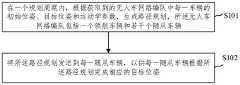
图1为依照本发明实施例的无人车网络编队的运动规划和协作定位方法示意图;1 is a schematic diagram of a method for motion planning and cooperative positioning of an unmanned vehicle network formation according to an embodiment of the present invention;
图2为依照本发明实施例的无人车网络编队的运动规划和协作定位方法的逻辑流程图;FIG. 2 is a logic flow chart of a method for motion planning and cooperative positioning of an unmanned vehicle network formation according to an embodiment of the present invention;
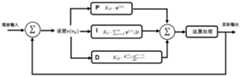
图3为依照本发明实施例的PID控制器流程图;3 is a flowchart of a PID controller according to an embodiment of the present invention;
图4为依照本发明实施例的系统分层式体系结构示意图;4 is a schematic diagram of a system layered architecture according to an embodiment of the present invention;
图5为依照本发明实施例的Dubins路径示意图;5 is a schematic diagram of a Dubins path according to an embodiment of the present invention;
图6为依照本发明实施例的场景中无人车的运动建模示意图;6 is a schematic diagram of motion modeling of an unmanned vehicle in a scene according to an embodiment of the present invention;
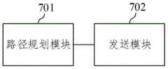
图7为依照本发明实施例的无人车网络编队的运动规划和协作定位装置示意图;7 is a schematic diagram of a motion planning and cooperative positioning device for an unmanned vehicle network formation according to an embodiment of the present invention;
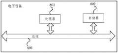
图8为依照本发明实施例的用于无人车网络编队的运动规划和协作定位的电子设备示意图。FIG. 8 is a schematic diagram of an electronic device for motion planning and cooperative positioning of an unmanned vehicle network formation according to an embodiment of the present invention.
具体实施方式Detailed ways
为了使本发明实施例的目的、技术方案和优点更加清楚,下面将结合本发明实施例中的附图,对本发明实施例中的技术方案进行清楚、完整地描述,显然,所描述的实施例是本发明一部分实施例,而不是全部的实施例。基于本发明的实施例,本领域普通技术人员在没有做出创造性劳动前提下所获得的所有其他实施例,都属于本发明保护的范围。In order to make the purposes, technical solutions and advantages of the embodiments of the present invention clearer, the technical solutions in the embodiments of the present invention will be described clearly and completely below with reference to the accompanying drawings in the embodiments of the present invention. Obviously, the described embodiments These are some embodiments of the present invention, but not all embodiments. Based on the embodiments of the present invention, all other embodiments obtained by those of ordinary skill in the art without creative work fall within the protection scope of the present invention.
图1为依照本发明实施例的无人车网络编队的运动规划和协作定位方法示意图,如图1所示,本发明实施例提供一种无人车网络编队的运动规划和协作定位方法,其执行主体为无人车网络编队的领航车辆,该方法包括:FIG. 1 is a schematic diagram of a method for motion planning and cooperative positioning of an unmanned vehicle network formation according to an embodiment of the present invention. As shown in FIG. 1 , an embodiment of the present invention provides a motion planning and cooperative positioning method for an unmanned vehicle network formation. The execution subject is the pilot vehicle of the unmanned vehicle network formation, and the method includes:
步骤S101、在一个规划周期内,根据获取到的无人车网络编队中每一车辆的初始位姿、目标位姿和运动学参数,生成路径规划,所述无人车网络编队包括一个领航车辆和若干个随从车辆;Step S101, in a planning cycle, generate a path plan according to the obtained initial pose, target pose and kinematic parameters of each vehicle in the unmanned vehicle network formation, where the unmanned vehicle network formation includes a pilot vehicle and several accompanying vehicles;
步骤S102、将所述路径规划发送到每一随从车辆,以供每一随从车辆根据所述路径规划完成相应的目标位姿。Step S102: Send the path plan to each follower vehicle, so that each follower vehicle can complete the corresponding target pose according to the path plan.
具体的,在一个大规模的无人车网络编队中,给定一个领航车辆和若干随从车辆,首先,需要将目标队形(任务)通过终端发送给领航单元,目标队形中包含每一随从车辆的目标位姿。Specifically, in a large-scale unmanned vehicle network formation, given a leader vehicle and several follower vehicles, first, the target formation (task) needs to be sent to the lead unit through the terminal, and the target formation includes each follower. The target pose of the vehicle.
在一个规划周期内,领航车辆根据获取到的无人车网络编队中每一车辆的初始位姿、目标位姿和运动学参数,生成路径规划。In a planning cycle, the leading vehicle generates a path plan according to the obtained initial pose, target pose and kinematic parameters of each vehicle in the unmanned vehicle network formation.
然后,领航车辆通过自带的超宽带模块将路径规划发送到每一随从车辆,每一随从车辆根据从领航车辆获取的路径规划完成相应的目标位姿。最终完成队形。Then, the leading vehicle sends the path plan to each follower vehicle through the built-in ultra-wideband module, and each follower vehicle completes the corresponding target pose according to the path plan obtained from the lead vehicle. Final formation.
本发明实施例提供的无人车网络编队的运动规划和协作定位方法,采用分层式体系结构,设置领航车辆和随从车辆;领航车辆统一规划最优路径,将整体方案分配调度,随从车辆分布式自主控制,完成任务。该方法仅需要领航车辆配置较高性能的定位设备和计算设备,随从车辆通过相互协作完成精确定位,增加了网络的相对定位精度,保证系统在低数据量获取情况下的高定位精度,提高了定位效率。The method for motion planning and cooperative positioning of an unmanned vehicle network formation provided by the embodiment of the present invention adopts a layered architecture, and sets up a pilot vehicle and a follower vehicle; the lead vehicle uniformly plans the optimal path, allocates and dispatches the overall scheme, and distributes the follower vehicles. autonomous control to complete tasks. This method only requires the pilot vehicle to be equipped with high-performance positioning equipment and computing equipment, and the follower vehicle completes precise positioning through mutual cooperation, which increases the relative positioning accuracy of the network, ensures the high positioning accuracy of the system under the condition of low data acquisition, and improves the performance of the system. positioning efficiency.
在上述实施例的基础上,进一步地,所述方法还包括:On the basis of the foregoing embodiment, further, the method further includes:
接收每个随从车辆反馈的位姿信息;Receive the pose information fed back by each follower vehicle;
根据所述位姿信息判断每个随从车辆是否完成相应的目标位姿;Judging whether each follower vehicle has completed the corresponding target pose according to the pose information;
若判断获知存在任一随从车辆未完成相应的目标位姿,则进入下一个规划周期,重新规划路径。If it is determined that any follower vehicle has not completed the corresponding target pose, enter the next planning cycle and re-plan the path.
具体的,图2为依照本发明实施例的无人车网络编队的运动规划和协作定位方法的逻辑流程图,如图2所示,领航车辆接收终端发送的指令,指令中包含目标队形;领航车辆根据获取到的无人车网络编队中每一车辆的初始位姿、目标位姿和运动学参数,生成路径规划;领航车辆将路径规划发送到每一随从车辆,在得到理想路径规划,即领航车辆发送的路径规划后,各随从车辆将自主控制,完成目标位姿。运动控制的过程中主要依靠经典PID控制器来实现。Specifically, FIG. 2 is a logic flow chart of a method for motion planning and cooperative positioning of an unmanned vehicle network formation according to an embodiment of the present invention. As shown in FIG. 2 , the pilot vehicle receives an instruction sent by the terminal, and the instruction includes the target formation; The leading vehicle generates a path plan according to the obtained initial pose, target pose and kinematic parameters of each vehicle in the unmanned vehicle network formation; the leading vehicle sends the path plan to each follower vehicle, and after obtaining the ideal path plan, That is, after the path planning sent by the leading vehicle, each follower vehicle will control itself to complete the target pose. The process of motion control mainly relies on the classical PID controller to realize.
在运动控制过程中,领航车辆接收每个随从车辆反馈的位姿信息;During the motion control process, the leading vehicle receives the pose information fed back by each follower vehicle;
领航车辆根据反馈的位姿信息判断每个随从车辆是否完成相应的目标位姿;若判断获知存在任一随从车辆未完成相应的目标位姿,则将反馈误差反馈给相应的随从车辆,进入下一个规划周期,重新规划路径,若判断获知所有的随从车辆都完成相应的目标位姿,领航车辆继续判断有无新指令,若有新指令,则接收新指令,若无新指令,则完成队形。The leading vehicle judges whether each follower vehicle has completed the corresponding target posture according to the feedback posture information; if it is judged that any follower vehicle has not completed the corresponding target posture, the feedback error will be fed back to the corresponding follower vehicle, and the next step will be entered. In one planning cycle, re-plan the path. If it is judged that all the follower vehicles have completed the corresponding target pose, the leading vehicle continues to judge whether there is a new command. If there is a new command, it will receive the new command. If there is no new command, the team will be completed. shape.
图3为依照本发明实施例的PID控制器流程图,如图3所示,本发明实施例提供的方法,通过PID反馈调节的方式将整个编队精准而平滑地控制到目标队形,即,根据理想航迹x*和估计所得位姿


本发明实施例提供的无人车网络编队的运动规划和协作定位方法,采用分层式体系结构,设置领航车辆和随从车辆;领航车辆统一规划最优路径,将整体方案分配调度,随从车辆分布式自主控制,完成任务。该方法仅需要领航车辆配置较高性能的定位设备和计算设备,随从车辆通过相互协作完成精确定位,增加了网络的相对定位精度,保证系统在低数据量获取情况下的高定位精度,提高了定位效率。The method for motion planning and cooperative positioning of an unmanned vehicle network formation provided by the embodiment of the present invention adopts a layered architecture, and sets up a pilot vehicle and a follower vehicle; the lead vehicle uniformly plans the optimal path, allocates and dispatches the overall scheme, and distributes the follower vehicles. autonomous control to complete tasks. This method only requires the pilot vehicle to be equipped with high-performance positioning equipment and computing equipment, and the follower vehicle completes precise positioning through mutual cooperation, which increases the relative positioning accuracy of the network, ensures the high positioning accuracy of the system under the condition of low data acquisition, and improves the performance of the system. positioning efficiency.
在以上各实施例的基础上,进一步地,所述根据获取到的无人车网络编队中每一车辆的初始位姿、目标位姿和运动学参数,生成路径规划具体为:On the basis of the above embodiments, further, according to the obtained initial pose, target pose and kinematic parameters of each vehicle in the unmanned vehicle network formation, the generated path plan is specifically:
将获取到的无人车网络编队中每一车辆的初始位姿、目标位姿和运动学参数输入至预设的优化模型,输出多种Dubins路径;Input the obtained initial pose, target pose and kinematic parameters of each vehicle in the unmanned vehicle network formation into the preset optimization model, and output various Dubins paths;
选择所述多种Dubins路径中最短的路径,作为路径规划。The shortest path among the multiple Dubins paths is selected as the path planning.
其中,所述优化模型为:Wherein, the optimization model is:
minimize Fminimize F
subjest to p*(n+1)=f(p*(n),u*(n))subjest to p*(n+1) = f(p*(n) , u*(n) )


p*(0) & p*(N)p*(0) & p*(N)
其中,F为代价函数,


具体的,图4为依照本发明实施例的系统分层式体系结构示意图,如图4所示,领航单元在获取无人车网络编队的拓扑结构后,构建系统分层式体系结构,以领航单元为坐标原点,根据各随从单元的初始坐标和目标位置,建立各节点的状态空间和测量空间,将车辆的速度、加速度、角速度和转弯曲率等运动学参数纳入滤波范围。特殊的,以第i辆车n时刻状态和测量为例,其状态空间和测量空间设计如下:Specifically, FIG. 4 is a schematic diagram of a system layered architecture according to an embodiment of the present invention. As shown in FIG. 4 , after acquiring the topology of the unmanned vehicle network formation, the pilot unit builds a system layered architecture to guide the navigation. The unit is the origin of the coordinates. According to the initial coordinates and target positions of each follower unit, the state space and measurement space of each node are established, and the kinematic parameters such as vehicle speed, acceleration, angular velocity and turning curvature are included in the filtering range. Specially, taking the state and measurement of the i-th vehicle at time n as an example, its state space and measurement space are designed as follows:

其中,状态空间


具体方法为:The specific method is:
设计代价函数

minimize Fminimize F
subjest to p*(n+1)=f(p*(n),u*(n))subjest to p*(n+1) = f(p*(n) , u*(n) )


p*(0) & p*(N)p*(0) & p*(N)
图6为依照本发明实施例的场景中无人车的运动建模示意图,如图6所示,此处的f(·)是在运动过程中速度、加速度等物理量遵循运动学定律以及遵循的几何关系函数。此处对几何关系则做了如下近似:FIG. 6 is a schematic diagram of motion modeling of an unmanned vehicle in a scene according to an embodiment of the present invention. As shown in FIG. 6 , f( ) here is that physical quantities such as speed and acceleration follow the laws of kinematics and are followed during the motion process. Geometric relationship function. The geometric relationship is approximated as follows:


本发明实施例提供的无人车网络编队的运动规划和协作定位方法,采用分层式体系结构,设置领航车辆和随从车辆;领航车辆统一规划最优路径,将整体方案分配调度,随从车辆分布式自主控制,完成任务。路径规划部分考虑到实际情况中的最大曲率与速度限制等约束条件,采取Dubins最短路径规划方式,设计出最短路径,具有实用性强,路径最优等特性。协作定位部分通过扩展卡尔曼滤波,利用UWB测距、惯性导航、陀螺仪等易于采集的进行信息融合,并且对传感器和存储空间的要求低,所测量数据极易获得,易于存储,处理方便,所以有低延时的优点,同时消除了位姿估计的不确定性,增加了网络的相对定位精度,保证系统在低数据量获取情况下的高定位精度,提高了定位效率。The method for motion planning and cooperative positioning of an unmanned vehicle network formation provided by the embodiment of the present invention adopts a layered architecture, and sets up a pilot vehicle and a follower vehicle; the lead vehicle uniformly plans the optimal path, allocates and dispatches the overall scheme, and distributes the follower vehicles. autonomous control to complete tasks. The path planning part takes into account the constraints such as the maximum curvature and speed limit in the actual situation, and adopts the Dubins shortest path planning method to design the shortest path, which has the characteristics of strong practicability and optimal path. The cooperative positioning part uses the extended Kalman filter to fuse information that is easy to collect using UWB ranging, inertial navigation, gyroscope, etc., and has low requirements for sensors and storage space. The measured data is extremely easy to obtain, easy to store, and easy to process. Therefore, it has the advantages of low latency, and at the same time eliminates the uncertainty of pose estimation, increases the relative positioning accuracy of the network, ensures the high positioning accuracy of the system in the case of low data acquisition, and improves the positioning efficiency.
在以上各实施例的基础上,进一步地,所述初始位姿由随从车辆基于获取到的相对观测数据,利用扩展卡尔曼滤波算法得到。On the basis of the above embodiments, further, the initial pose is obtained by the follower vehicle using the extended Kalman filter algorithm based on the obtained relative observation data.
具体的,在初次进行路径规划是,由于没有任何关于位置的先验信息,首先需通过无人车自带的超宽带模块进行相互测距结算得到网络的拓扑结构,此处采用余弦定理结算即可:任意三辆车若得知两两之间的距离,通过A=arccos[(b2+c2-a2)/2bc]即可结算出任意两边之间夹角,进而得到整个网络的拓扑结构。Specifically, in the initial path planning, since there is no prior information about the location, the network topology structure needs to be obtained by mutual ranging and settlement through the ultra-broadband module that comes with the unmanned vehicle. Yes: If any three vehicles know the distance between them, the angle between any two sides can be calculated by A=arccos[(b2 +c2 -a2 )/2bc], and then the distance between the entire network can be calculated. Topology.
初始位姿由随从车辆基于获取到的相对观测数据,利用扩展卡尔曼滤波算法得到,具体步骤如下:The initial pose is obtained by the follower vehicle based on the relative observation data obtained by using the extended Kalman filter algorithm. The specific steps are as follows:
对于状态方程


如图5所示,此处在时间间隙足够短的情况下,对小车单位时隙内的运动做了线性化处理,将其质心走过的圆弧段近似为直线,所以根据本发明的运动建模,我们有如下关系:As shown in Figure 5, here, when the time gap is short enough, the movement in the unit time slot of the trolley is linearized, and the arc segment traveled by the center of mass is approximated as a straight line, so the movement according to the present invention Modeling, we have the following relationship:

f(·)和h(·)是非线性的,利用雅各比矩阵对系统做一阶泰勒近似,可以得到


L(n)是作用在u(n)上的变换模型,本发明中由f(·)对u泰勒一阶近似得到,
H(n)是观测模型,它把n时刻的真实状态空间映射成观测空间;本发明中由h(·)对x泰勒一阶近似得到,
所以扩展卡尔曼滤波过程可分为两个阶段:状态预测与测量更新,具体表述为:Therefore, the extended Kalman filtering process can be divided into two stages: state prediction and measurement update, which are specifically expressed as:
状态预测阶段:State prediction stage:

测量更新阶段:Measurement update phase:

此处通过测量更新能够修正状态预测过程中的状态误差,主要通过卡尔曼增益系数来控制预测和测量的权重,通过信息融合弥补不确定性。Here, the state error in the state prediction process can be corrected through measurement update, the weight of prediction and measurement is mainly controlled by the Kalman gain coefficient, and the uncertainty is compensated by information fusion.
本发明实施例提供的无人车网络编队的运动规划和协作定位方法,采用分层式体系结构,设置领航车辆和随从车辆;领航车辆统一规划最优路径,将整体方案分配调度,随从车辆分布式自主控制,完成任务。路径规划部分考虑到实际情况中的最大曲率与速度限制等约束条件,采取Dubins最短路径规划方式,设计出最短路径,具有实用性强,路径最优等特性。协作定位部分通过扩展卡尔曼滤波,利用UWB测距、惯性导航、陀螺仪等易于采集的进行信息融合,并且对传感器和存储空间的要求低,所测量数据极易获得,易于存储,处理方便,所以有低延时的优点,同时消除了位姿估计的不确定性,增加了网络的相对定位精度,保证系统在低数据量获取情况下的高定位精度,提高了定位效率。The method for motion planning and cooperative positioning of an unmanned vehicle network formation provided by the embodiment of the present invention adopts a layered architecture, and sets up a pilot vehicle and a follower vehicle; the lead vehicle uniformly plans the optimal path, allocates and dispatches the overall scheme, and distributes the follower vehicles. autonomous control to complete tasks. The path planning part takes into account the constraints such as the maximum curvature and speed limit in the actual situation, and adopts the Dubins shortest path planning method to design the shortest path, which has the characteristics of strong practicability and optimal path. The cooperative positioning part uses the extended Kalman filter to fuse information that is easy to collect using UWB ranging, inertial navigation, gyroscope, etc., and has low requirements for sensors and storage space. The measured data is extremely easy to obtain, easy to store, and easy to process. Therefore, it has the advantages of low latency, and at the same time eliminates the uncertainty of pose estimation, increases the relative positioning accuracy of the network, ensures the high positioning accuracy of the system in the case of low data acquisition, and improves the positioning efficiency.
图7为依照本发明实施例的无人车网络编队的运动规划和协作定位装置示意图,如图7所示,本发明实施例提供一种无人车网络编队的运动规划和协作定位装置,包括路径规划模块701和发送模块702,其中,路径规划模块701用于在一个规划周期内,根据获取到的无人车网络编队中每一车辆的初始位姿、目标位姿和运动学参数,生成路径规划,所述无人车网络编队包括一个领航车辆和若干个随从车辆;FIG. 7 is a schematic diagram of a motion planning and cooperative positioning device for an unmanned vehicle network formation according to an embodiment of the present invention. As shown in FIG. 7 , an embodiment of the present invention provides a motion planning and cooperative positioning device for an unmanned vehicle network formation, including: The
发送模块702用于将所述路径规划发送到每一随从车辆,以供每一随从车辆根据所述路径规划完成相应的目标位姿。The sending
本发明实施例提供一种无人车网络编队的运动规划和协作定位装置,用于完成上述实施例中所述的方法,通过本实施例提供的装置完成上述实施例中所述的方法的具体步骤与上述实施例相同,此处不再赘述。An embodiment of the present invention provides a motion planning and cooperative positioning device for an unmanned vehicle network formation, which is used to implement the method described in the above embodiment, and the specific method described in the above embodiment is completed by the device provided in this embodiment. The steps are the same as those in the above-mentioned embodiment, and are not repeated here.
本发明实施例提供的无人车网络编队的运动规划和协作定位装置,采用分层式体系结构,设置领航车辆和随从车辆;领航车辆统一规划最优路径,将整体方案分配调度,随从车辆分布式自主控制,完成任务。路径规划部分考虑到实际情况中的最大曲率与速度限制等约束条件,采取Dubins最短路径规划方式,设计出最短路径,具有实用性强,路径最优等特性。协作定位部分通过扩展卡尔曼滤波,利用UWB测距、惯性导航、陀螺仪等易于采集的进行信息融合,并且对传感器和存储空间的要求低,所测量数据极易获得,易于存储,处理方便,所以有低延时的优点,同时消除了位姿估计的不确定性,增加了网络的相对定位精度,保证系统在低数据量获取情况下的高定位精度,提高了定位效率。The motion planning and cooperative positioning device for the unmanned vehicle network formation provided by the embodiment of the present invention adopts a layered architecture, and sets up a pilot vehicle and a follower vehicle; the lead vehicle uniformly plans the optimal path, assigns and schedules the overall plan, and distributes the follower vehicles. autonomous control to complete tasks. The path planning part takes into account the constraints such as the maximum curvature and speed limit in the actual situation, and adopts the Dubins shortest path planning method to design the shortest path, which has the characteristics of strong practicability and optimal path. The cooperative positioning part uses the extended Kalman filter to fuse information that is easy to collect using UWB ranging, inertial navigation, gyroscope, etc., and has low requirements for sensors and storage space. The measured data is extremely easy to obtain, easy to store, and easy to process. Therefore, it has the advantages of low latency, and at the same time eliminates the uncertainty of pose estimation, increases the relative positioning accuracy of the network, ensures the high positioning accuracy of the system in the case of low data acquisition, and improves the positioning efficiency.
在上述实施例的基础上,进一步地,所述装置还包括:On the basis of the above embodiment, further, the device further includes:
接收模块,用于接收每个随从车辆反馈的位姿信息;The receiving module is used to receive the pose information fed back by each follower vehicle;
判断模块,用于根据所述位姿信息判断每个随从车辆是否完成相应的目标位姿;a judging module for judging whether each follower vehicle has completed the corresponding target posture according to the posture information;
若判断获知存在任一随从车辆未完成相应的目标位姿,则进入下一个规划周期,所述路径规划模块,用于重新规划路径。If it is determined that any follower vehicle has not completed the corresponding target pose, the next planning cycle is entered, and the path planning module is used to re-plan the path.
本发明实施例提供一种无人车网络编队的运动规划和协作定位装置,用于完成上述实施例中所述的方法,通过本实施例提供的装置完成上述实施例中所述的方法的具体步骤与上述实施例相同,此处不再赘述。An embodiment of the present invention provides a motion planning and cooperative positioning device for an unmanned vehicle network formation, which is used to implement the method described in the above embodiment, and the specific method described in the above embodiment is completed by the device provided in this embodiment. The steps are the same as those in the above-mentioned embodiment, and are not repeated here.
本发明实施例提供的无人车网络编队的运动规划和协作定位装置,采用分层式体系结构,设置领航车辆和随从车辆;领航车辆统一规划最优路径,将整体方案分配调度,随从车辆分布式自主控制,完成任务。路径规划部分考虑到实际情况中的最大曲率与速度限制等约束条件,采取Dubins最短路径规划方式,设计出最短路径,具有实用性强,路径最优等特性。协作定位部分通过扩展卡尔曼滤波,利用UWB测距、惯性导航、陀螺仪等易于采集的进行信息融合,并且对传感器和存储空间的要求低,所测量数据极易获得,易于存储,处理方便,所以有低延时的优点,同时消除了位姿估计的不确定性,增加了网络的相对定位精度,保证系统在低数据量获取情况下的高定位精度,提高了定位效率。The motion planning and cooperative positioning device for the unmanned vehicle network formation provided by the embodiment of the present invention adopts a layered architecture, and sets up a pilot vehicle and a follower vehicle; the lead vehicle uniformly plans the optimal path, assigns and schedules the overall plan, and distributes the follower vehicles. autonomous control to complete tasks. The path planning part takes into account the constraints such as the maximum curvature and speed limit in the actual situation, and adopts the Dubins shortest path planning method to design the shortest path, which has the characteristics of strong practicability and optimal path. The cooperative positioning part uses the extended Kalman filter to fuse information that is easy to collect using UWB ranging, inertial navigation, gyroscope, etc., and has low requirements for sensors and storage space. The measured data is extremely easy to obtain, easy to store, and easy to process. Therefore, it has the advantages of low latency, and at the same time eliminates the uncertainty of pose estimation, increases the relative positioning accuracy of the network, ensures the high positioning accuracy of the system in the case of low data acquisition, and improves the positioning efficiency.
在以上各实施例的基础上,进一步地,所述路径规划模块,具体用于:On the basis of the above embodiments, further, the path planning module is specifically used for:
将获取到的无人车网络编队中每一车辆的初始位姿、目标位姿和运动学参数输入至预设的优化模型,输出多种Dubins路径;Input the obtained initial pose, target pose and kinematic parameters of each vehicle in the unmanned vehicle network formation into the preset optimization model, and output various Dubins paths;
选择所述多种Dubins路径中最短的路径,作为路径规划。The shortest path among the multiple Dubins paths is selected as the path planning.
本发明实施例提供一种无人车网络编队的运动规划和协作定位装置,用于完成上述实施例中所述的方法,通过本实施例提供的装置完成上述实施例中所述的方法的具体步骤与上述实施例相同,此处不再赘述。An embodiment of the present invention provides a motion planning and cooperative positioning device for an unmanned vehicle network formation, which is used to implement the method described in the above embodiment, and the specific method described in the above embodiment is completed by the device provided in this embodiment. The steps are the same as those in the above-mentioned embodiment, and are not repeated here.
本发明实施例提供的无人车网络编队的运动规划和协作定位装置,采用分层式体系结构,设置领航车辆和随从车辆;领航车辆统一规划最优路径,将整体方案分配调度,随从车辆分布式自主控制,完成任务。路径规划部分考虑到实际情况中的最大曲率与速度限制等约束条件,采取Dubins最短路径规划方式,设计出最短路径,具有实用性强,路径最优等特性。协作定位部分通过扩展卡尔曼滤波,利用UWB测距、惯性导航、陀螺仪等易于采集的进行信息融合,并且对传感器和存储空间的要求低,所测量数据极易获得,易于存储,处理方便,所以有低延时的优点,同时消除了位姿估计的不确定性,增加了网络的相对定位精度,保证系统在低数据量获取情况下的高定位精度,提高了定位效率。The motion planning and cooperative positioning device for the unmanned vehicle network formation provided by the embodiment of the present invention adopts a layered architecture, and sets up a pilot vehicle and a follower vehicle; the lead vehicle uniformly plans the optimal path, assigns and schedules the overall plan, and distributes the follower vehicles. autonomous control to complete tasks. The path planning part takes into account the constraints such as the maximum curvature and speed limit in the actual situation, and adopts the Dubins shortest path planning method to design the shortest path, which has the characteristics of strong practicability and optimal path. The cooperative positioning part uses the extended Kalman filter to fuse information that is easy to collect using UWB ranging, inertial navigation, gyroscope, etc., and has low requirements for sensors and storage space. The measured data is extremely easy to obtain, easy to store, and easy to process. Therefore, it has the advantages of low latency, and at the same time eliminates the uncertainty of pose estimation, increases the relative positioning accuracy of the network, ensures the high positioning accuracy of the system in the case of low data acquisition, and improves the positioning efficiency.
图8为依照本发明实施例的用于无人车网络编队的运动规划和协作定位的电子设备示意图,如图8所示,所述设备包括:处理器801、存储器802和总线803;FIG. 8 is a schematic diagram of an electronic device for motion planning and cooperative positioning of unmanned vehicle network formation according to an embodiment of the present invention. As shown in FIG. 8 , the device includes: a
其中,处理器801和存储器802通过所述总线803完成相互间的通信;Wherein, the
处理器801用于调用存储器802中的程序指令,以执行上述各方法实施例所提供的方法,例如包括:在一个规划周期内,根据获取到的无人车网络编队中每一车辆的初始位姿、目标位姿和运动学参数,生成路径规划,所述无人车网络编队包括一个领航车辆和若干个随从车辆;将所述路径规划发送到每一随从车辆,以供每一随从车辆根据所述路径规划完成相应的目标位姿。The
本发明实施例公开一种计算机程序产品,所述计算机程序产品包括存储在非暂态计算机可读存储介质上的计算机程序,所述计算机程序包括程序指令,当所述程序指令被计算机执行时,计算机能够执行上述各方法实施例所提供的方法,例如包括:在一个规划周期内,根据获取到的无人车网络编队中每一车辆的初始位姿、目标位姿和运动学参数,生成路径规划,所述无人车网络编队包括一个领航车辆和若干个随从车辆;将所述路径规划发送到每一随从车辆,以供每一随从车辆根据所述路径规划完成相应的目标位姿。An embodiment of the present invention discloses a computer program product, where the computer program product includes a computer program stored on a non-transitory computer-readable storage medium, the computer program includes program instructions, and when the program instructions are executed by a computer, The computer can execute the methods provided by the above method embodiments, for example, including: in a planning cycle, generating a path according to the obtained initial pose, target pose and kinematic parameters of each vehicle in the unmanned vehicle network formation. planning, the unmanned vehicle network formation includes a leader vehicle and several follower vehicles; the path plan is sent to each follower vehicle, so that each follower vehicle can complete the corresponding target pose according to the path plan.
本发明实施例提供一种非暂态计算机可读存储介质,所述非暂态计算机可读存储介质存储计算机指令,所述计算机指令使所述计算机执行上述各方法实施例所提供的方法,例如包括:在一个规划周期内,根据获取到的无人车网络编队中每一车辆的初始位姿、目标位姿和运动学参数,生成路径规划,所述无人车网络编队包括一个领航车辆和若干个随从车辆;将所述路径规划发送到每一随从车辆,以供每一随从车辆根据所述路径规划完成相应的目标位姿。Embodiments of the present invention provide a non-transitory computer-readable storage medium, where the non-transitory computer-readable storage medium stores computer instructions, and the computer instructions cause the computer to execute the methods provided by the foregoing method embodiments, for example Including: in a planning cycle, generating a path plan according to the obtained initial pose, target pose and kinematic parameters of each vehicle in the unmanned vehicle network formation, where the unmanned vehicle network formation includes a pilot vehicle and several follower vehicles; sending the path plan to each follower vehicle, so that each follower vehicle can complete the corresponding target pose according to the path plan.
本领域普通技术人员可以理解:实现上述方法实施例的全部或部分步骤可以通过程序指令相关的硬件来完成,前述的程序可以存储于一计算机可读取存储介质中,该程序在执行时,执行包括上述方法实施例的步骤;而前述的存储介质包括:ROM、RAM、磁碟或者光盘等各种可以存储程序代码的介质。Those of ordinary skill in the art can understand that all or part of the steps of implementing the above method embodiments can be completed by program instructions related to hardware, the aforementioned program can be stored in a computer-readable storage medium, and when the program is executed, execute It includes the steps of the above method embodiments; and the aforementioned storage medium includes: ROM, RAM, magnetic disk or optical disk and other media that can store program codes.
以上所描述的装置及设备等实施例仅仅是示意性的,其中所述作为分离部件说明的单元可以是或者也可以不是物理上分开的,作为单元显示的部件可以是或者也可以不是物理单元,即可以位于一个地方,或者也可以分布到多个网络单元上。可以根据实际的需要选择其中的部分或者全部模块来实现本实施例方案的目的。本领域普通技术人员在不付出创造性的劳动的情况下,即可以理解并实施。The above-described embodiments such as apparatuses and devices are merely illustrative, wherein the units described as separate components may or may not be physically separated, and the components displayed as units may or may not be physical units, That is, it can be located in one place, or it can be distributed to multiple network elements. Some or all of the modules may be selected according to actual needs to achieve the purpose of the solution in this embodiment. Those of ordinary skill in the art can understand and implement it without creative effort.
通过以上的实施方式的描述,本领域的技术人员可以清楚地了解到各实施方式可借助软件加必需的通用硬件平台的方式来实现,当然也可以通过硬件。基于这样的理解,上述技术方案本质上或者说对现有技术做出贡献的部分可以以软件产品的形式体现出来,该计算机软件产品可以存储在计算机可读存储介质中,如ROM/RAM、磁碟、光盘等,包括若干指令用以使得一台计算机设备(可以是个人计算机,服务器,或者网络设备等)执行各个实施例或者实施例的某些部分所述的方法。From the description of the above embodiments, those skilled in the art can clearly understand that each embodiment can be implemented by means of software plus a necessary general hardware platform, and certainly can also be implemented by hardware. Based on this understanding, the above-mentioned technical solutions can be embodied in the form of software products in essence or the parts that make contributions to the prior art, and the computer software products can be stored in computer-readable storage media, such as ROM/RAM, magnetic A disc, an optical disc, etc., includes several instructions for causing a computer device (which may be a personal computer, a server, or a network device, etc.) to perform the methods described in various embodiments or some parts of the embodiments.
最后应说明的是:以上实施例仅用以说明本发明的技术方案,而非对其限制;尽管参照前述实施例对本发明进行了详细的说明,本领域的普通技术人员应当理解:其依然可以对前述各实施例所记载的技术方案进行修改,或者对其中部分技术特征进行等同替换;而这些修改或者替换,并不使相应技术方案的本质脱离本发明各实施例技术方案的精神和范围。Finally, it should be noted that the above embodiments are only used to illustrate the technical solutions of the present invention, but not to limit them; although the present invention has been described in detail with reference to the foregoing embodiments, those of ordinary skill in the art should understand that it can still be The technical solutions described in the foregoing embodiments are modified, or some technical features thereof are equivalently replaced; and these modifications or replacements do not make the essence of the corresponding technical solutions deviate from the spirit and scope of the technical solutions of the embodiments of the present invention.
Claims (7)


Priority Applications (1)
| Application Number | Priority Date | Filing Date | Title |
|---|---|---|---|
| CN201810433350.5ACN108664024B (en) | 2018-05-08 | 2018-05-08 | Motion planning and cooperative positioning method and device for unmanned vehicle network formation |
Applications Claiming Priority (1)
| Application Number | Priority Date | Filing Date | Title |
|---|---|---|---|
| CN201810433350.5ACN108664024B (en) | 2018-05-08 | 2018-05-08 | Motion planning and cooperative positioning method and device for unmanned vehicle network formation |
Publications (2)
| Publication Number | Publication Date |
|---|---|
| CN108664024A CN108664024A (en) | 2018-10-16 |
| CN108664024Btrue CN108664024B (en) | 2020-09-25 |
Family
ID=63778768
Family Applications (1)
| Application Number | Title | Priority Date | Filing Date |
|---|---|---|---|
| CN201810433350.5AActiveCN108664024B (en) | 2018-05-08 | 2018-05-08 | Motion planning and cooperative positioning method and device for unmanned vehicle network formation |
Country Status (1)
| Country | Link |
|---|---|
| CN (1) | CN108664024B (en) |
Families Citing this family (16)
| Publication number | Priority date | Publication date | Assignee | Title |
|---|---|---|---|---|
| CN109445438B (en)* | 2018-12-05 | 2022-03-04 | 英华达(上海)科技有限公司 | Cruise control method and system of cruise device based on map sharing |
| CN110085023A (en)* | 2019-04-10 | 2019-08-02 | 同济大学 | Relative position measurement system and method between a kind of vehicle of formation traveling fleet |
| CN110428603B (en)* | 2019-07-26 | 2021-04-23 | 北京主线科技有限公司 | Method and device for controlling following vehicle running in container truck formation |
| CN111735466B (en)* | 2020-01-02 | 2021-11-12 | 北京京东乾石科技有限公司 | A multi-vehicle cooperative trajectory planning method, device, equipment and storage medium |
| CN113110932B (en)* | 2020-01-13 | 2024-12-17 | 北京地平线机器人技术研发有限公司 | Planning result generation method and device and electronic equipment |
| CN113781762B (en)* | 2020-06-09 | 2022-09-13 | 大唐高鸿智联科技(重庆)有限公司 | A driving method, device and equipment for formation vehicles and formation vehicles |
| CN112833876B (en)* | 2020-12-30 | 2022-02-11 | 西南科技大学 | Multi-robot cooperative positioning method integrating odometer and UWB |
| CN113003229B (en)* | 2021-02-26 | 2023-03-24 | 北京卫星制造厂有限公司 | Heterogeneous characteristic-oriented multi-agent cooperative autonomous transfer system for large equipment |
| CN113110441B (en)* | 2021-04-09 | 2022-11-18 | 江苏大学 | UWB-based cluster operation method for agricultural unmanned vehicles |
| CN113147764B (en)* | 2021-06-01 | 2022-08-16 | 吉林大学 | Vehicle control method based on hybrid potential function of cooperative adaptive cruise system |
| CN113467449B (en)* | 2021-06-30 | 2023-05-30 | 深圳市海柔创新科技有限公司 | Motorcade control method, motorcade control device, electronic equipment and storage medium |
| CN114987552B (en)* | 2022-06-28 | 2025-09-19 | 江苏盛海智能科技有限公司 | Method for unmanned driving to pass through barrier array and storage medium |
| CN115016523B (en)* | 2022-08-03 | 2022-12-13 | 西安羚控电子科技有限公司 | Cluster device control system, control method, cluster device and storage medium |
| CN116007628A (en)* | 2022-12-12 | 2023-04-25 | 北京理工大学重庆创新中心 | RFID-based path planning algorithm for vehicle-vehicle cooperative formation |
| CN116358548B (en)* | 2023-02-15 | 2025-05-27 | 清华大学 | Self-organizing network formation navigation method, system and storage medium based on relative positioning |
| CN120445243A (en)* | 2025-04-11 | 2025-08-08 | 中兵智能创新研究院有限公司 | A path planning method for unmanned vehicle platooning considering multiple factors |
Citations (6)
| Publication number | Priority date | Publication date | Assignee | Title |
|---|---|---|---|---|
| CN101685309A (en)* | 2008-09-24 | 2010-03-31 | 中国科学院自动化研究所 | Method for controlling multi-robot coordinated formation |
| CN104238554A (en)* | 2013-06-14 | 2014-12-24 | 江南大学 | Movable body formation control method through wireless sensor network |
| CN106094835A (en)* | 2016-08-01 | 2016-11-09 | 西北工业大学 | The dynamic formation control method of front-wheel drive vehicle type moving machine device people |
| KR20180025611A (en)* | 2016-09-01 | 2018-03-09 | 국민대학교산학협력단 | Autonomous driving system and autonomous driving method thereof |
| CN107860388A (en)* | 2017-10-27 | 2018-03-30 | 哈尔滨工程大学 | A kind of multirobot collaborative navigation location algorithm based on mixed topology structure |
| CN107943071A (en)* | 2017-11-03 | 2018-04-20 | 中国科学院自动化研究所 | The formation of unmanned vehicle keeps control method and system |
Family Cites Families (6)
| Publication number | Priority date | Publication date | Assignee | Title |
|---|---|---|---|---|
| CN101408433B (en)* | 2008-11-12 | 2012-07-18 | 深圳市凯立德欣软件技术有限公司 | Fleet navigation system, piloting navigation apparatus, sub-navigation apparatus and navigation method thereof |
| US9669828B2 (en)* | 2012-06-01 | 2017-06-06 | Toyota Motor Engineering & Manufacturing North America, Inc. | Cooperative driving and collision avoidance by distributed receding horizon control |
| CN103901887B (en)* | 2014-03-04 | 2017-05-24 | 重庆邮电大学 | Multi-moving-robot formation control method based on improved particle swarm optimization |
| CN104616541A (en)* | 2015-02-03 | 2015-05-13 | 吉林大学 | Fish streaming based non-signal intersection vehicle-vehicle cooperation control system |
| CN105527960A (en)* | 2015-12-18 | 2016-04-27 | 燕山大学 | Mobile robot formation control method based on leader-follow |
| CN107798861B (en)* | 2017-11-30 | 2021-03-02 | 湖北汽车工业学院 | A kind of vehicle cooperative formation driving method and system |
- 2018
- 2018-05-08CNCN201810433350.5Apatent/CN108664024B/enactiveActive
Patent Citations (6)
| Publication number | Priority date | Publication date | Assignee | Title |
|---|---|---|---|---|
| CN101685309A (en)* | 2008-09-24 | 2010-03-31 | 中国科学院自动化研究所 | Method for controlling multi-robot coordinated formation |
| CN104238554A (en)* | 2013-06-14 | 2014-12-24 | 江南大学 | Movable body formation control method through wireless sensor network |
| CN106094835A (en)* | 2016-08-01 | 2016-11-09 | 西北工业大学 | The dynamic formation control method of front-wheel drive vehicle type moving machine device people |
| KR20180025611A (en)* | 2016-09-01 | 2018-03-09 | 국민대학교산학협력단 | Autonomous driving system and autonomous driving method thereof |
| CN107860388A (en)* | 2017-10-27 | 2018-03-30 | 哈尔滨工程大学 | A kind of multirobot collaborative navigation location algorithm based on mixed topology structure |
| CN107943071A (en)* | 2017-11-03 | 2018-04-20 | 中国科学院自动化研究所 | The formation of unmanned vehicle keeps control method and system |
Non-Patent Citations (2)
| Title |
|---|
| Decentralized overlapping tracking control of a formation of autonomous unmanned vehicles;Srdjan S. Stankovic 等;《2009 American Control Conference》;20090710;第3878-3883页* |
| 多机器人的路径规划关键技术及其挑战;陈超毅 等;《第三十四届中国控制会议论文集(E卷)》;20150731;第7171-7174页* |
Also Published As
| Publication number | Publication date |
|---|---|
| CN108664024A (en) | 2018-10-16 |
Similar Documents
| Publication | Publication Date | Title |
|---|---|---|
| CN108664024B (en) | Motion planning and cooperative positioning method and device for unmanned vehicle network formation | |
| Elbanhawi et al. | Continuous path smoothing for car-like robots using B-spline curves | |
| CN114771551A (en) | Method and device for planning track of automatic driving vehicle and automatic driving vehicle | |
| CN101943916A (en) | Kalman filter prediction-based robot obstacle avoidance method | |
| CN113085850A (en) | Vehicle obstacle avoidance method and device, electronic equipment and storage medium | |
| RU2479015C1 (en) | Method of defining motion path of self-contained vehicle in dynamic medium | |
| CN109434831A (en) | Robot operation method and device, robot, electronic device and readable medium | |
| Park et al. | Formation reconfiguration control with collision avoidance of nonholonomic mobile robots | |
| Ribeiro et al. | Nonlinear model predictive visual path following control to autonomous mobile robots | |
| CN111076724B (en) | Three-dimensional laser positioning method and system | |
| Signifredi et al. | A general purpose approach for global and local path planning combination | |
| Antipov et al. | Dynamic models design for processing motion reference signals for mobile robots | |
| Chen et al. | Path Planning and Motion Control of Robot Dog Through Rough Terrain Based on Vision Navigation | |
| Liang et al. | Distributed fixed-time control for leader-steered rigid shape formation with prescribed performance | |
| Boutalbi et al. | A high-performance control algorithm based on a curvature-dependent decoupled planning approach and flatness concepts for non-holonomic mobile robots | |
| Liu et al. | Trajectory prediction and visual localization of snake robot based on BiLSTM neural network | |
| Li et al. | SEB-Naver: A SE (2)-based Local Navigation Framework for Car-like Robots on Uneven Terrain | |
| Wang et al. | Research on automated guided vehicle (AGV) path tracking control based on laser simultaneous localization and mapping (SLAM) | |
| Qiu et al. | Real-Time Terrain-Aware Path Optimization for Off-Road Autonomous Vehicles | |
| Pham et al. | CBFs-Based Model Predictive Control for Obstacle Avoidance With Tilt Angle Limitation for Ball-Balancing Robots | |
| Mutti et al. | Distributed lidar based control for cooperative transportation with multiple autonomous mobile robots | |
| Suganya et al. | Soft computing controller based path planning wheeled mobile robot | |
| Hua et al. | Deep Reinforcement Learning-Based Hierarchical Motion Planning Strategy for Multirotors | |
| Ghorab et al. | Multi-Waypoint Path Planning and Motion Control for Non-holonomic Mobile Robots in Agricultural Applications | |
| Jaroszek et al. | Localization of the wheeled mobile robot based on multi-sensor data fusion |
Legal Events
| Date | Code | Title | Description |
|---|---|---|---|
| PB01 | Publication | ||
| PB01 | Publication | ||
| SE01 | Entry into force of request for substantive examination | ||
| SE01 | Entry into force of request for substantive examination | ||
| GR01 | Patent grant | ||
| GR01 | Patent grant |