CN108618204B - Atomizer and electronic cigarette - Google Patents
Atomizer and electronic cigaretteDownload PDFInfo
- Publication number
- CN108618204B CN108618204BCN201710172952.5ACN201710172952ACN108618204BCN 108618204 BCN108618204 BCN 108618204BCN 201710172952 ACN201710172952 ACN 201710172952ACN 108618204 BCN108618204 BCN 108618204B
- Authority
- CN
- China
- Prior art keywords
- liquid
- atomizing
- piece
- cavity
- atomizing head
- Prior art date
- Legal status (The legal status is an assumption and is not a legal conclusion. Google has not performed a legal analysis and makes no representation as to the accuracy of the status listed.)
- Active
Links
Images


Classifications
- A24F47/008—
Landscapes
- Electrostatic Spraying Apparatus (AREA)
Abstract
Description
Translated fromChinese技术领域technical field
本发明涉及模拟吸烟技术领域,特别地,涉及一种雾化器及电子烟。The invention relates to the technical field of simulated smoking, in particular, to an atomizer and an electronic cigarette.
背景技术Background technique
现有的电子烟结构中,用于雾化烟液的雾化头一般设置在储液腔的内部或储液腔的下部,由于液体压力或重力作用,会使得过多的烟液进入至雾化腔内,从而产生漏液现象。另一方面,由于用作导液的导液件往往是纤维绳,烟液依靠渗透作用进入至雾化腔内,因此,导液速率较慢,当用户抽吸过快而使加热功率过高时,会因导液效率低而产生干烧现象,从而降低了用户的使用体验。导液速率是指单位时间内液体从导液件一端顺着导液件向另一端运动过程中所走过的路程。另外,导液件往往较软,当电子烟在斜置或晃动等情况下,容导致导液件倾斜或变形,从而摆脱与烟液的接触,烟液传导不良,影响电子烟的正常工作。In the existing electronic cigarette structure, the atomizing head for atomizing the liquid is generally arranged inside the liquid storage cavity or at the lower part of the liquid storage cavity. into the chemical cavity, resulting in liquid leakage. On the other hand, since the liquid guiding member used for liquid guiding is often a fiber rope, the liquid smoke enters into the atomization cavity by osmosis. Therefore, the liquid guiding rate is relatively slow. When the user draws too fast, the heating power is too high. When the liquid conduction efficiency is low, a dry burning phenomenon will occur, thereby reducing the user experience. The liquid guiding rate refers to the distance traveled by the liquid in a unit time during the movement of the liquid from one end of the liquid guiding member to the other end along the liquid guiding member. In addition, the liquid guide is often soft. When the electronic cigarette is tilted or shaken, the liquid guide can be tilted or deformed, so as to get rid of the contact with the e-liquid, and the e-liquid conduction is poor, which affects the normal operation of the e-cigarette.
发明内容SUMMARY OF THE INVENTION
基于此,有必要提供一种雾化器及电子烟,以解决漏液、干烧及烟液传导不良中的至少一个问题。Based on this, it is necessary to provide an atomizer and an electronic cigarette to solve at least one of the problems of liquid leakage, dry burning and poor e-liquid conduction.
本发明解决其技术问题所要采用的技术方案是:一种雾化器,所述雾化器包括具有储液腔的储液件以及安装在所述储液件上方且具有雾化腔的雾化头,所述储液件的底部设有电极,所述雾化头包括导液件以及伸入所述储液件内的极柱,所述极柱内部中空且与所述电极电性连接,所述导液件的下端设于所述极柱内,所述导液件的上端设于所述雾化腔内,所述极柱上设有与所述储液腔连通的进液孔。The technical solution adopted by the present invention to solve the technical problem is: an atomizer, the atomizer includes a liquid storage member with a liquid storage chamber and an atomizer installed above the liquid storage member and having an atomization chamber head, the bottom of the liquid storage part is provided with an electrode, the atomization head includes a liquid guide part and a pole extending into the liquid storage part, the inside of the pole post is hollow and is electrically connected with the electrode, The lower end of the liquid guiding member is arranged in the pole, the upper end of the liquid guiding member is arranged in the atomizing cavity, and the pole pole is provided with a liquid inlet hole communicating with the liquid storage cavity.
进一步地,所述极柱远离所述电极的一端开口,所述极柱内设有容置腔,所述导液件至少部分收容于所述容置腔内,所述进液孔有多个且与所述容置腔相连通。Further, one end of the pole away from the electrode is open, the pole is provided with a accommodating cavity, the liquid-conducting member is at least partially accommodated in the accommodating cavity, and there are multiple liquid inlet holes. and communicate with the accommodating cavity.
进一步地,所述雾化头还包括雾化套管以及发热件,所述极柱的上端与所述雾化套管连接,所述雾化腔由所述雾化套管的内腔形成,所述发热件设于所述雾化腔内且与所述极柱电性连接。Further, the atomizing head also includes an atomizing sleeve and a heating element, the upper end of the pole is connected to the atomizing sleeve, and the atomizing cavity is formed by the inner cavity of the atomizing sleeve, The heating element is arranged in the atomizing cavity and is electrically connected with the pole.
进一步地,所述导液件包括第一吸液件以及至少与所述第一吸液件贴合的第二吸液件,所述第一吸液件能够使得烟液沿所述第一吸液件传导至所述雾化腔内,所述第二吸液件夹设于所述发热件与所述第一吸液件之间,所述第一吸液件的导液速率大于所述第二吸液件的导液速率。Further, the liquid-guiding member includes a first liquid-absorbing member and a second liquid-absorbing member at least attached to the first liquid-absorbing member, and the first liquid-absorbing member can make the smoke liquid flow along the first liquid-absorbing member. The liquid part is conducted into the atomization chamber, the second liquid absorbing part is sandwiched between the heating part and the first liquid absorbing part, and the liquid guiding rate of the first liquid absorbing part is higher than that of the Liquid delivery rate of the second pipette.
进一步地,所述导液件一部分收容于所述容置腔中,所述导液件另一部分收容于所述雾化腔中,收容于所述容置腔内的所述导液件为所述第一吸液件,收容于所述雾化腔中的所述导液件包括所述第一吸液件和所述第二吸液件。Further, a part of the liquid guiding member is accommodated in the accommodating cavity, the other part of the liquid guiding member is accommodated in the atomizing cavity, and the liquid guiding member accommodated in the accommodating cavity is the The first liquid absorbing member, the liquid guiding member accommodated in the atomizing cavity includes the first liquid absorbing member and the second liquid absorbing member.
进一步地,所述第一吸液件为金属绳,所述第二吸液件为棉花、纤维绳、玻璃纤维、多孔陶瓷中任一种。Further, the first liquid-absorbing member is a metal rope, and the second liquid-absorbing member is any one of cotton, fiber rope, glass fiber, and porous ceramics.
进一步地,所述雾化头还包括雾化头固定座以及连接在所述雾化头固定座上端的烟嘴,所述烟嘴与所述雾化腔相连通,所述雾化套管收容于所述雾化头固定座内,所述雾化套管的侧壁上设置有进气槽,所述雾化头固定座的侧壁上设置有进气孔,所述进气槽分别与所述进气孔及所述雾化腔相连通。Further, the atomizing head further includes an atomizing head fixing seat and a cigarette holder connected to the upper end of the atomizing head fixing seat, the cigarette holder is communicated with the atomizing cavity, and the atomizing sleeve is accommodated in the In the atomizing head fixing seat, an air inlet groove is arranged on the side wall of the atomizing sleeve, and an air inlet hole is arranged on the side wall of the atomizing head fixing seat. The air inlet is communicated with the atomizing cavity.
进一步地,所述雾化头还包括连接在所述雾化套管上端的雾化头上盖,所述雾化头上盖呈两端贯通的环状结构,所述雾化头上盖的侧壁上设置有防滑纹。Further, the atomizing head further comprises an upper cover of the atomizing head connected to the upper end of the atomizing sleeve, the upper cover of the atomizing head is a ring-shaped structure with two ends running through, and the upper cover of the atomizing head is in the form of a ring. Anti-skid patterns are provided on the side walls.
一种电子烟,所述电子烟包括前述任一项所述的雾化器。An electronic cigarette, the electronic cigarette comprises the atomizer described in any one of the foregoing.
进一步地,所述电子烟还包括壳体以及设于所述壳体内部的电池组件,所述储液件收容于所述壳体内,所述电池组件包括设于所述储液件下方的电池,所述电极与所述电池电性连接。Further, the electronic cigarette further includes a casing and a battery assembly disposed inside the casing, the liquid storage member is accommodated in the casing, and the battery assembly includes a battery disposed below the liquid storage member , the electrodes are electrically connected to the battery.
本发明的有益效果是:本发明提供的雾化头、雾化器及电子烟,极柱既作为电性元件与电极接触导电,同时也作为容置腔容纳导液件,容置腔可以对导液件限位,极柱上开设有进液孔,烟液可以从进液孔进入被导液件传输。结构更加简化,拆卸方便,导液速率快。The beneficial effects of the present invention are: in the atomizing head, the atomizer and the electronic cigarette provided by the present invention, the pole not only acts as an electrical element to contact the electrode and conduct electricity, but also serves as a accommodating cavity to accommodate a liquid-conducting member, and the accommodating cavity can The liquid guiding member is limited, and the pole is provided with a liquid inlet hole, and the smoke liquid can enter from the liquid inlet hole and be transmitted by the liquid guiding member. The structure is more simplified, the disassembly is convenient, and the liquid conduction rate is fast.
同时导液件设置为第二吸液件与第一吸液件相互贴合的方式,导液速率快,避免了干烧现象,且操作便捷,从而提升了用户的使用体验。At the same time, the liquid guiding member is arranged in such a way that the second liquid absorbing member and the first liquid absorbing member are attached to each other, the liquid guiding speed is fast, the dry burning phenomenon is avoided, and the operation is convenient, thereby improving the user experience.
附图说明Description of drawings
下面结合附图和实施例对本发明作进一步说明。The present invention will be further described below with reference to the accompanying drawings and embodiments.
图1是本发明实施例一的电子烟的结构示意图;1 is a schematic structural diagram of an electronic cigarette according to Embodiment 1 of the present invention;
图2是图1所示电子烟的左视图;Fig. 2 is the left side view of the electronic cigarette shown in Fig. 1;
图3是图2所示电子烟沿A-A的剖视图;3 is a cross-sectional view of the electronic cigarette shown in FIG. 2 along A-A;
图4是图3所示电子烟中雾化头固定座的结构示意图;FIG. 4 is a schematic structural diagram of an atomizing head holder in the electronic cigarette shown in FIG. 3;
图5是图1所示电子烟中雾化头的立体图;(省略雾化头固定座)Fig. 5 is a perspective view of the atomizing head in the electronic cigarette shown in Fig. 1; (atomizing head fixing seat is omitted)
图6是图5所示电子烟中雾化头的主视图;Fig. 6 is the front view of the atomizing head in the electronic cigarette shown in Fig. 5;
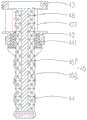
图7是图6所示电子烟中雾化头沿B-B的剖视图;Fig. 7 is the sectional view along B-B of the atomizing head in the electronic cigarette shown in Fig. 6;
图8是本发明实施例二的电子烟中雾化头的剖视图。8 is a cross-sectional view of the atomizing head in the electronic cigarette according to the second embodiment of the present invention.
图中零部件名称及其编号分别为:The names and numbers of the parts in the figure are:
电子烟100 壳体10 电池组件20
储液件30 雾化头40 烟嘴50
螺纹孔11 电池21 电极22Threaded
储液腔31 绝缘密封件32 雾化头固定座41
雾化套管42 雾化头上盖43 极柱44
导液件45 发热件46 抽吸部51Liquid guiding
连接管411 第一外螺纹412 进气孔413Connecting
内螺纹414 第二外螺纹421 雾化腔422Internal thread 414 Second
进气槽423 防滑纹431 绝缘件441
进液孔442 第一吸液件451 第二吸液件452
具体实施方式Detailed ways
现在结合附图对本发明作详细的说明。此图为简化的示意图,仅以示意方式说明本发明的基本结构,因此其仅显示与本发明有关的构成。The present invention will now be described in detail with reference to the accompanying drawings. This figure is a simplified schematic diagram, and only illustrates the basic structure of the present invention in a schematic manner, so it only shows the structure related to the present invention.
请参阅图1-图3,本发明提供了一种电子烟100,该电子烟100包括壳体10、安装在壳体10上的雾化器(图未标出)以及收容于壳体10内的电池组件20,其中,雾化器包括连接在外壳10上的雾化头40、安装在雾化头40上的烟嘴50以及收容在外壳10内部的储液件30。Referring to FIGS. 1-3 , the present invention provides an
请参阅图3,壳体10大致呈中空的盒状结构,做为其他零部件安装以及用户使用时握持的载体。本实施方式中,壳体10由塑料材质制成,成本低廉,且易于加工。可以理解地,在其他未示出的实施方式中,壳体10还可以由金属或玻璃材料制成。Referring to FIG. 3 , the
请参阅图3,电池组件20包括电池21,电池21固定收容在壳体10的底部。Referring to FIG. 3 , the
请参阅图3,储液件30大致呈上端具有开口的筒状结构,储液件30的内部空间形成用于存储烟液的储液腔31。储液件30固定设置在电池21的上方,储液件30的底部设有与电池21连接的电极22,电极22的一端贯穿储液件30的底部,为了起到绝缘作用以及避免烟液泄漏,电池22与储液件30之间夹设有绝缘密封件32。本实施方式中,绝缘密封件32由硅胶材料制成,可以理解地,在其他未示出的实施方式中,绝缘密封件32还可以由橡胶等其它绝缘材料制成。Referring to FIG. 3 , the
请参阅图3,本实施方式中,壳体10的上端面对应储液件30的开口端设置有螺纹孔11,该螺纹孔11与储液腔31相连通。Referring to FIG. 3 , in this embodiment, the upper end surface of the
请参阅图3,雾化头40包括雾化头固定座41、雾化套管42、雾化头上盖43、极柱44、导液件45以及发热件46。Referring to FIG. 3 , the atomizing
雾化头固定座41连接在壳体10的螺纹孔11上,具体地,请参阅图4,本实施方式中,雾化头固定座41大致呈上端具有开口的中空筒状结构,雾化头固定座41下端面的中心处沿雾化头固定座41的轴向向下延伸形成连通雾化头固定座41内腔的连接管411,连接管411的外壁上设置有与螺纹孔11相配合的第一外螺纹412,雾化头固定座41通过第一外螺纹412和螺纹孔11的配合与壳体10可拆卸地连接。可以理解地,在其他未示出的实施方式中,雾化头固定座41与壳体10还可以通过压接或卡接的方式实现可拆卸地连接。The atomizing
雾化头固定座41的侧壁上设有两个相对设置的进气孔413,以便于外部空气进入。可以理解地,进气孔413的数量还可以有一个或两个以上。Two oppositely arranged air inlet holes 413 are provided on the side wall of the atomizing
本实施方式中,连接管411的内壁上设置有内螺纹414。In this embodiment, an inner thread 414 is provided on the inner wall of the connecting
请参阅图6,雾化套管42大致呈两端具有开口的中空筒状结构,雾化套管42固定收容在雾化头固定座41内,雾化套管42的下端设置有与内螺纹414相配合的第二外螺纹421,雾化套管42通过第二外螺纹421和内螺纹414的配合与雾化头固定座41可拆卸地连接。可以理解地,在其他未示出的实施方式中,雾化套管42与雾化头固定座41还可以通过压接或卡接的方式实现可拆卸地连接。Please refer to FIG. 6 , the
请同时参阅图5和图7,雾化套管42的内部空间形成雾化腔422,雾化套管42的侧壁上设有四个均布设置的进气槽423,进气槽423分别与雾化腔422以及进气孔413相连通。可以理解地,进气槽423至少有一个。Please refer to FIG. 5 and FIG. 7 at the same time, an atomization cavity 422 is formed in the inner space of the
雾化头40安装在所述储液件30上方,即雾化腔422设置在储液腔31的上方,烟液通过毛细作用由储液腔31进入至雾化腔422内雾化成烟雾,避免了过多烟液进入至雾化腔422内而发生泄漏的情况。The atomizing
请参阅图5,雾化头上盖43大致呈两端贯通的圆环状结构,雾化头上盖43通过压接的方式固定连接在雾化套管42的上端。用户欲将雾化套管42拆卸时,只需通过用手转动雾化头上盖43即可,雾化套管42会在雾化头上盖43的带动下旋出而与雾化头固定座41分离。为了增大摩擦力,易于拆卸,雾化头上盖43的侧壁上设置有防滑纹431。Referring to FIG. 5 , the
可以理解地,雾化头上盖43还可以通过卡接或螺纹连接的方式与雾化套管42连接,还可以理解地,雾化头上盖43与雾化套管42为一体成型结构。It can be understood that the
请同时参阅图3和图7,极柱44大致呈上端具有开口的中空筒状结构,极柱44的上端与雾化套管42的下端固定连接,极柱44的下端收容在储液腔31内,极柱44与电极22接触并能够电性导通。为了使极柱44与雾化套管42绝缘,极柱44与雾化套管42之间夹设有绝缘件441,绝缘件441可以由硅胶或橡胶等其他绝缘材料制成。Please refer to FIG. 3 and FIG. 7 at the same time, the
请同时参阅图5和图6,极柱44的内腔形成用于收容导液件45的容置腔(图未标出),极柱44的侧壁上设置有多个进液孔442,进液孔442分别与储液腔31以及容置腔相连通。本实施方式中,进液孔442均匀间隔交错设置在极柱44的侧壁上,以保证导液件45的各部分能够均匀导液。用户使用时,储液腔31内的烟液能够尽可能多的被导液件45吸收,吸液速率高。同时,能够对收容在极柱44内的导液件45起到限位作用,防止导液件45发生位置偏离而无法吸液,避免烟液传导不良的问题。Please refer to FIG. 5 and FIG. 6 at the same time, the inner cavity of the
请参阅图7,导液件45一部分收容在极柱44的容置腔内,另一部分向上延伸至雾化腔422内,发热件46套设在导液件45上且收容于雾化腔422内。Please refer to FIG. 7 , a part of the
导液件45包括相互包覆的第一吸液件451以及第二吸液件452,且第一吸液件451的导液速率大于第二吸液件452的导液速率。本实施方式中,第二吸液件452包覆在第一吸液件451上。The
第一吸液件451是能够供烟液发生毛细作用的元件,本实施方式中,第一吸液件451是由金属丝缠绕而成的金属绳,所述金属丝的材料可以是铁、镍、铬、钨、钛、钢、铜中的任一种或其合金。金属绳由金属丝呈螺旋形紧密缠绕而成,成型后的金属绳的外周面上形成一道狭窄的螺旋状通道,金属绳的下端浸没在烟液中,烟液由于毛细作用,能够沿着所述的通道向上传导至雾化腔422内。可以理解地,第一吸液件451还可以由多跟金属丝搓捻而形成的金属绳,金属丝之间形成的通道也能够供烟液发生毛细作用而传导至雾化腔422内。还可以理解地,第一吸液件451还可以是设置有狭窄通道的玻璃、陶瓷等元件,只需满足能够供烟液发生毛细作用而向上传导即可,此处不作限制。The first
第二吸液件452是能够供烟液发生渗透作用的元件,第二吸液件452由具有绝缘和吸液功能的材料制成,第二吸液件452可以是棉花、纤维绳、玻璃纤维、多孔陶瓷中的一种,第二吸液件452一方面能够将第一吸液件451与发热件46绝缘,避免发生短路故障。另一方面,由于极柱44在导电过程中会产生热量,第二吸液件452设置在第一吸液件451和极柱44之间,能够避免极柱44与第二吸液件452接触而被烧毁的情况。本发明的一个实施方式中,第一吸液件451为钢丝绳,第二吸液件452为棉花。The second
具体的,发热件46套设在第二吸液件452上。发热件46通过导线(图未示出)与极柱44电性连接,本实施方式中,发热件46为套设在导液件45上的螺旋形加热丝,可以理解地,发热件46还可以是套设在导液件45上的加热网管。Specifically, the
可以理解地,在其他未示出的实施方式中,第二吸液件452套设在发热件46上,第一吸液件451包覆在第二吸液件452上,安装时,保证第一吸液件451与极柱44之间存有间隙,避免发生短路。综上,第二吸液件452夹设在第一吸液件451以及发热件46之间即可。It can be understood that in other embodiments not shown, the second
可以理解地,第一吸液件451与第二吸液件452只需至少部分贴合即可,如第一吸液件451及第二吸液件452均为条形片状结构,第一吸液件451的上端与第二吸液件452的下端部分贴合,同样能够使得烟液沿第一吸液件451上升直至到达第二吸液件452上,在发热件46的作用下雾化成烟雾。It can be understood that the first
请参阅图3,烟嘴50大致呈下端具有开口的中空筒状结构,烟嘴50上端面的中心处沿烟嘴50的轴向向上延伸形成连通烟嘴50内腔的抽吸部51,烟嘴50的下端通过插接的方式与雾化头固定座41的上端可拆卸地连接。用户抽吸时,可含住抽吸部51进行抽吸,可以理解地,还可以在抽吸部51上安装连通件,用户通过含住连通件进行抽吸。Referring to FIG. 3 , the
为了提升烟嘴50与雾化头固定座41连接处的气密性,烟嘴50与雾化头固定座41之间设置有硅胶圈或橡胶圈等密封件(图未标出)。In order to improve the air tightness of the connection between the
下面结合附图说明本发明的电子烟100的使用过程。The following describes the use process of the
用户抽吸时,第一吸液件451的下端浸没在储液腔31的烟液中,在毛细作用下,烟液沿着第一吸液件451向上传导进入至雾化腔422内,随后烟液经由第二吸液件452与发热件46接触,在发热件46的加热作用下雾化成烟雾,烟雾充满在雾化腔422内。同时,外部空气依次经由进气孔413以及进气槽423进入至雾化腔422内,混合烟雾后经由烟嘴50的抽吸部51进入至用户口中。When the user sucks, the lower end of the first
本发明的电子烟100,需要向储液腔31添加烟液时,只需同时拆下雾化头40和烟嘴50,使储液件30的开口端裸露出来即可进行注液操作。可以理解地,该电子烟100还可以做为滴液电子烟使用,具体地,拆下烟嘴50,将烟液滴加在导液件45上即可,不需要向储液腔31内注入烟液。该电子烟100同时具有储液以及滴液功能,增加了使用乐趣,提升了用户的使用体验。In the
本发明的电子烟100,雾化腔422设置在储液腔31的上方,避免了储液腔31内的烟液由于液体压力或重力作用而过多地进入至雾化腔422内,从而有效避免了烟液泄漏。同时,烟液由于毛细作用而上升,导液速率快,即便是用户抽吸过快或加热功率过高,也不会出现干烧的现象。且结构简单,操作便捷,从而提升了用户的使用体验。In the
实施例二Embodiment 2
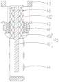
请参阅图8,本实施例二提供的电子烟(图为示出)与实施例一的电子烟100的区别就在于,极柱44的容置腔内还可以只设置第一吸液件451,而雾化腔422内既包括第一吸液件451也包括第二吸液件452,即所述导液件45一部分收容于所述容置腔中,所述导液件45另一部分收容于所述雾化腔422中,容置腔内的第一吸液件451将烟液吸收后并向上传导,烟液到达雾化腔422内时再通过与第一吸液件451贴合的第二吸液件452到达发热件46处被加热雾化。本实施例二中,由于处于容置腔内的第一吸液件451直接与烟液接触,使得烟液传导更迅速,进一步避免了干烧现象的发生。同时,缩减了第二吸液件452的用料,节省了生产成本。Referring to FIG. 8 , the difference between the electronic cigarette (shown in the figure) provided in the second embodiment and the
以上述依据本发明的理想实施例为启示,通过上述的说明内容,相关的工作人员完全可以在不偏离本发明的范围内,进行多样的变更以及修改。本项发明的技术范围并不局限于说明书上的内容,必须要根据权利要求范围来确定其技术性范围。Taking the above ideal embodiments according to the present invention as inspiration, and through the above description, relevant personnel can make various changes and modifications without departing from the scope of the present invention. The technical scope of the present invention is not limited to the contents in the specification, and the technical scope must be determined according to the scope of the claims.
Claims (10)
Priority Applications (2)
| Application Number | Priority Date | Filing Date | Title |
|---|---|---|---|
| CN201710172952.5ACN108618204B (en) | 2017-03-22 | 2017-03-22 | Atomizer and electronic cigarette |
| PCT/CN2018/077763WO2018171402A1 (en) | 2017-03-22 | 2018-03-01 | Atomizing head, atomizer and electronic cigarette |
Applications Claiming Priority (1)
| Application Number | Priority Date | Filing Date | Title |
|---|---|---|---|
| CN201710172952.5ACN108618204B (en) | 2017-03-22 | 2017-03-22 | Atomizer and electronic cigarette |
Publications (2)
| Publication Number | Publication Date |
|---|---|
| CN108618204A CN108618204A (en) | 2018-10-09 |
| CN108618204Btrue CN108618204B (en) | 2020-06-19 |
Family
ID=63707087
Family Applications (1)
| Application Number | Title | Priority Date | Filing Date |
|---|---|---|---|
| CN201710172952.5AActiveCN108618204B (en) | 2017-03-22 | 2017-03-22 | Atomizer and electronic cigarette |
Country Status (1)
| Country | Link |
|---|---|
| CN (1) | CN108618204B (en) |
Families Citing this family (5)
| Publication number | Priority date | Publication date | Assignee | Title |
|---|---|---|---|---|
| CN111728275A (en)* | 2019-03-22 | 2020-10-02 | 常州市派腾电子技术服务有限公司 | Cartridges and Electronic Cigarettes |
| CN111109678B (en)* | 2020-01-17 | 2025-06-10 | 深圳麦克韦尔科技有限公司 | Electronic atomization device, atomizer and atomization assembly thereof |
| CN111109677B (en)* | 2020-01-17 | 2025-05-09 | 深圳麦克韦尔科技有限公司 | Electronic atomization device and atomizer and atomization assembly thereof |
| CN119073658A (en)* | 2023-06-05 | 2024-12-06 | 爱奇迹(香港)有限公司 | Atomizer device and electronic atomizer |
| CN119214381A (en)* | 2023-06-30 | 2024-12-31 | 爱奇迹(香港)有限公司 | Atomization components and atomization devices |
Citations (7)
| Publication number | Priority date | Publication date | Assignee | Title |
|---|---|---|---|---|
| CN202999299U (en)* | 2012-12-05 | 2013-06-19 | 刘秋明 | Magnetic connection electronic cigarette with connector |
| WO2013091251A1 (en)* | 2011-12-23 | 2013-06-27 | Liu Qiuming | Electronic cigarette suction nozzle |
| CN203435687U (en)* | 2013-08-31 | 2014-02-19 | 卓尔悦(常州)电子科技有限公司 | Atomizing head |
| CN203457811U (en)* | 2013-09-17 | 2014-03-05 | 欧俊彪 | Electronic cigarette |
| CN203851816U (en)* | 2014-04-28 | 2014-10-01 | 深圳市合元科技有限公司 | Atomizer and electronic cigarette with atomizer |
| CN203986138U (en)* | 2014-04-30 | 2014-12-10 | 惠州市吉瑞科技有限公司 | A kind of electronic cigarette |
| CN205831073U (en)* | 2016-06-27 | 2016-12-28 | 卓尔悦欧洲控股有限公司 | Atomization core apparatus and electronic cigarette |
- 2017
- 2017-03-22CNCN201710172952.5Apatent/CN108618204B/enactiveActive
Patent Citations (7)
| Publication number | Priority date | Publication date | Assignee | Title |
|---|---|---|---|---|
| WO2013091251A1 (en)* | 2011-12-23 | 2013-06-27 | Liu Qiuming | Electronic cigarette suction nozzle |
| CN202999299U (en)* | 2012-12-05 | 2013-06-19 | 刘秋明 | Magnetic connection electronic cigarette with connector |
| CN203435687U (en)* | 2013-08-31 | 2014-02-19 | 卓尔悦(常州)电子科技有限公司 | Atomizing head |
| CN203457811U (en)* | 2013-09-17 | 2014-03-05 | 欧俊彪 | Electronic cigarette |
| CN203851816U (en)* | 2014-04-28 | 2014-10-01 | 深圳市合元科技有限公司 | Atomizer and electronic cigarette with atomizer |
| CN203986138U (en)* | 2014-04-30 | 2014-12-10 | 惠州市吉瑞科技有限公司 | A kind of electronic cigarette |
| CN205831073U (en)* | 2016-06-27 | 2016-12-28 | 卓尔悦欧洲控股有限公司 | Atomization core apparatus and electronic cigarette |
Also Published As
| Publication number | Publication date |
|---|---|
| CN108618204A (en) | 2018-10-09 |
Similar Documents
| Publication | Publication Date | Title |
|---|---|---|
| CN206651392U (en) | Atomising head, atomizer and electronic cigarette | |
| CN108618204B (en) | Atomizer and electronic cigarette | |
| JP6737949B2 (en) | Disposable cigarette cartridge, atomizer and electronic cigarette | |
| US20180317559A1 (en) | Atomizing head, atomizer and electronic cigarette thereof | |
| CN103763952B (en) | Electronic cigarette suction nozzle | |
| EP2617303B1 (en) | Replaceable general atomizing head | |
| CN204444245U (en) | Removable atomization unit and the atomizer and the electronic cigarette that comprise this atomization unit | |
| US10306930B2 (en) | Heating device, and atomizing head, atomizer and electronic cigarette having the same | |
| CN108201175B (en) | Atomizing core, preparation method, atomizer, and electronic cigarette | |
| EP4042886A1 (en) | Ultrasonic atomizer | |
| CN106983177B (en) | Electronic cigarette and its atomizing device | |
| CN210869884U (en) | Atomizers and Electronic Cigarettes | |
| CN206729211U (en) | Electronic cigarette and its atomising device | |
| CA3185112A1 (en) | Electronic vaporization device | |
| WO2017190335A1 (en) | Electronic cigarette | |
| KR20160130342A (en) | Atomizing device for an electronic Cigarette | |
| CN207125320U (en) | Atomising head, atomizer and electronic cigarette | |
| CN209846172U (en) | Atomization component, atomizer and electronic cigarette | |
| WO2015131413A1 (en) | Electronic cigarette | |
| WO2025113587A1 (en) | Atomization apparatus and atomization device | |
| CN207400335U (en) | Atomizer and its electronic cigarette | |
| CN210124327U (en) | Atomizers and Electronic Cigarettes | |
| CN220109145U (en) | Atomization device and atomization equipment thereof | |
| CN210929641U (en) | Heating elements, heating structures, atomizing components, atomizers and electronic cigarettes | |
| CN210017899U (en) | Atomizer and electronic cigarette |
Legal Events
| Date | Code | Title | Description |
|---|---|---|---|
| PB01 | Publication | ||
| PB01 | Publication | ||
| SE01 | Entry into force of request for substantive examination | ||
| SE01 | Entry into force of request for substantive examination | ||
| GR01 | Patent grant | ||
| GR01 | Patent grant | ||
| TR01 | Transfer of patent right | ||
| TR01 | Transfer of patent right | Effective date of registration:20201225 Address after:518100 2 / F, 3 / F, 4 / F, area 1, building 14, hengmingzhu science and Technology Industrial Park, Gonghe community, Shajing street, Bao'an District, Shenzhen City, Guangdong Province Patentee after:Shenzhen Juwei Electronic Technology Co.,Ltd. Address before:Room 512, building 2, Fuchen garden, Xinbei District, Changzhou City, Jiangsu Province Patentee before:CHANGZHOU PATENT ELECTRONIC TECHNOLOGY Co.,Ltd. |